Thesis Proposal Mechanical Systems Redesign - engr.psu.edu Proposal Edited.pdf · Thesis Proposal...
20
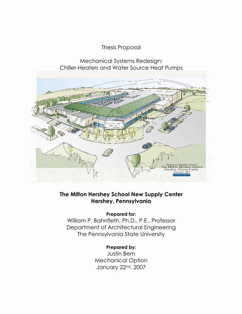
Thesis Proposal Mechanical Systems Redesign: Chiller-Heaters and Water Source Heat Pumps The Milton Hershey School New Supply Center Hershey, Pennsylvania Prepared for: William P. Bahnfleth, Ph.D., P.E., Professor Department of Architectural Engineering The Pennsylvania State University Prepared by: Justin Bem Mechanical Option January 22 nd , 2007
Transcript of Thesis Proposal Mechanical Systems Redesign - engr.psu.edu Proposal Edited.pdf · Thesis Proposal...
Thesis Proposal
Mechanical Systems Redesign:
Chiller-Heaters and Water Source Heat Pumps
The Milton Hershey School New Supply Center
Hershey, Pennsylvania
Prepared for:
William P. Bahnfleth, Ph.D., P.E., Professor
Department of Architectural Engineering
The Pennsylvania State University
Prepared by:
Justin Bem
Mechanical Option
January 22nd, 2007
Justin Bem Milton Hershey School Supply Center
Mechanical Option Hershey, Pennsylvania
Mechanical Systems Redesign - 1 -
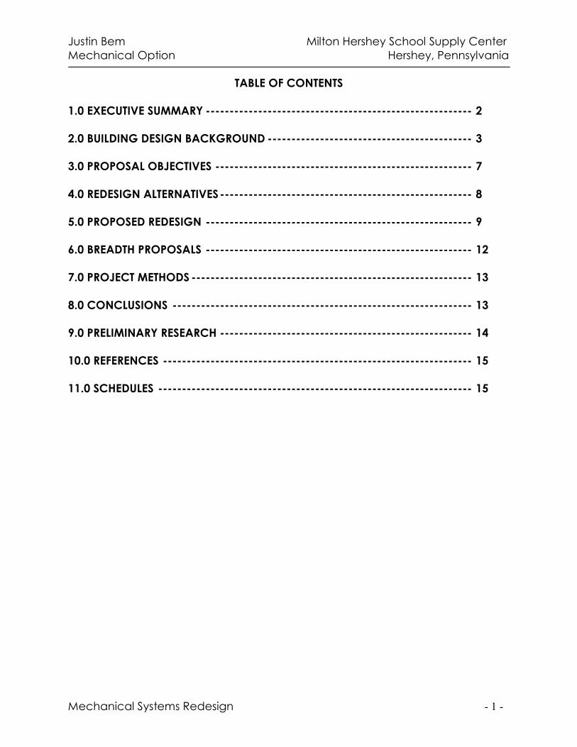
TABLE OF CONTENTS
1.0 EXECUTIVE SUMMARY -------------------------------------------------------- 2
2.0 BUILDING DESIGN BACKGROUND ------------------------------------------- 3
3.0 PROPOSAL OBJECTIVES ------------------------------------------------------ 7
4.0 REDESIGN ALTERNATIVES----------------------------------------------------- 8
5.0 PROPOSED REDESIGN -------------------------------------------------------- 9
6.0 BREADTH PROPOSALS -------------------------------------------------------- 12
7.0 PROJECT METHODS ----------------------------------------------------------- 13
8.0 CONCLUSIONS --------------------------------------------------------------- 13
9.0 PRELIMINARY RESEARCH ----------------------------------------------------- 14
10.0 REFERENCES ----------------------------------------------------------------- 15
11.0 SCHEDULES ------------------------------------------------------------------ 15
Justin Bem Milton Hershey School Supply Center
Mechanical Option Hershey, Pennsylvania
Mechanical Systems Redesign - 2 -
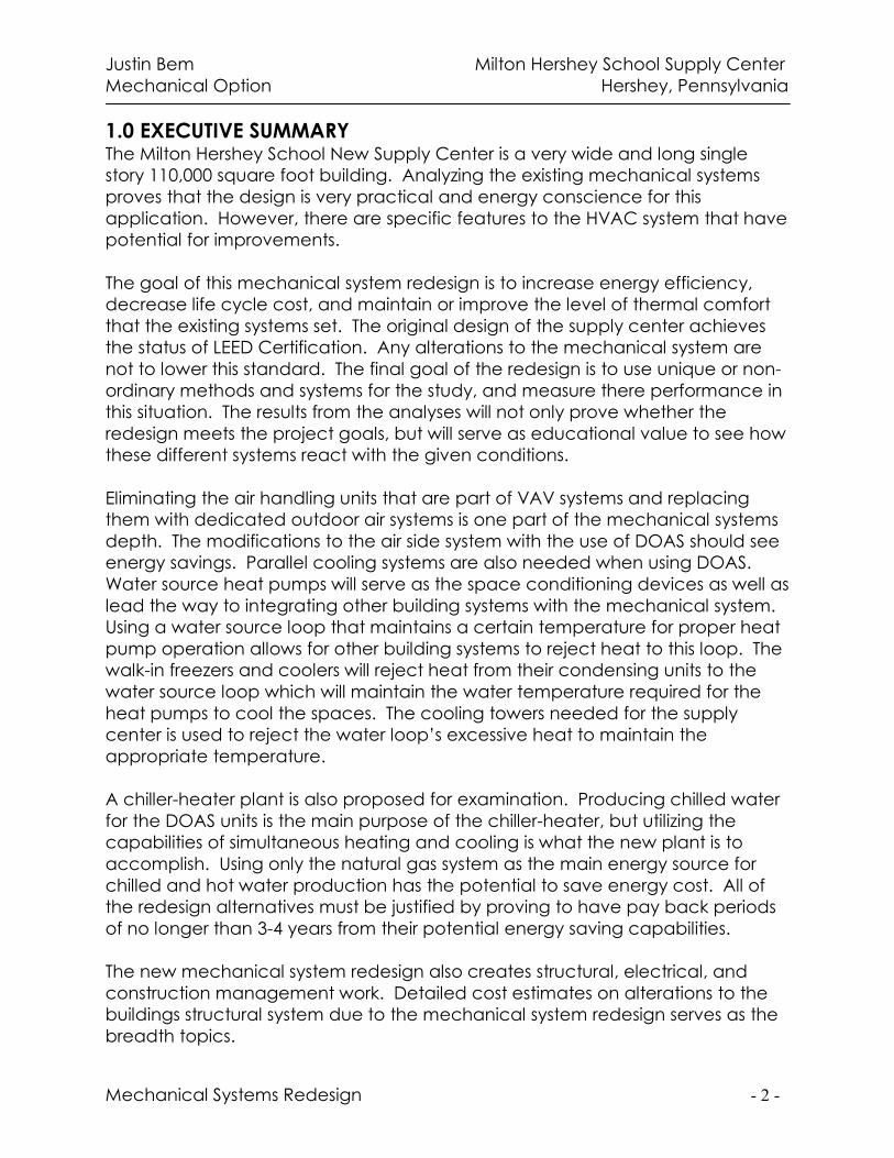
1.0 EXECUTIVE SUMMARY The Milton Hershey School New Supply Center is a very wide and long single
story 110,000 square foot building. Analyzing the existing mechanical systems
proves that the design is very practical and energy conscience for this
application. However, there are specific features to the HVAC system that have
potential for improvements.
The goal of this mechanical system redesign is to increase energy efficiency,
decrease life cycle cost, and maintain or improve the level of thermal comfort
that the existing systems set. The original design of the supply center achieves
the status of LEED Certification. Any alterations to the mechanical system are
not to lower this standard. The final goal of the redesign is to use unique or non-
ordinary methods and systems for the study, and measure there performance in
this situation. The results from the analyses will not only prove whether the
redesign meets the project goals, but will serve as educational value to see how
these different systems react with the given conditions.
Eliminating the air handling units that are part of VAV systems and replacing
them with dedicated outdoor air systems is one part of the mechanical systems
depth. The modifications to the air side system with the use of DOAS should see
energy savings. Parallel cooling systems are also needed when using DOAS.
Water source heat pumps will serve as the space conditioning devices as well as
lead the way to integrating other building systems with the mechanical system.
Using a water source loop that maintains a certain temperature for proper heat
pump operation allows for other building systems to reject heat to this loop. The
walk-in freezers and coolers will reject heat from their condensing units to the
water source loop which will maintain the water temperature required for the
heat pumps to cool the spaces. The cooling towers needed for the supply
center is used to reject the water loop’s excessive heat to maintain the
appropriate temperature.
A chiller-heater plant is also proposed for examination. Producing chilled water
for the DOAS units is the main purpose of the chiller-heater, but utilizing the
capabilities of simultaneous heating and cooling is what the new plant is to
accomplish. Using only the natural gas system as the main energy source for
chilled and hot water production has the potential to save energy cost. All of
the redesign alternatives must be justified by proving to have pay back periods
of no longer than 3-4 years from their potential energy saving capabilities.
The new mechanical system redesign also creates structural, electrical, and
construction management work. Detailed cost estimates on alterations to the
buildings structural system due to the mechanical system redesign serves as the
breadth topics.
Justin Bem Milton Hershey School Supply Center
Mechanical Option Hershey, Pennsylvania
Mechanical Systems Redesign - 3 -
2.0 BUILDING DESIGN BACKGROUND
The Milton Hershey School New Supply Center is a single story 110,000 square
foot building with four elevated mechanical mezzanine rooms and contains a
variety of spaces. The north and northwest sections of the building consists of
general office spaces and conference rooms. Located in the center of the
building is the food distribution center for the Milton Hershey School. This area
contains large freezers, refrigerators, and temperature controlled storage areas,
fifteen in all, totaling to 13,600 square feet to go along with its central food
preparation spaces.
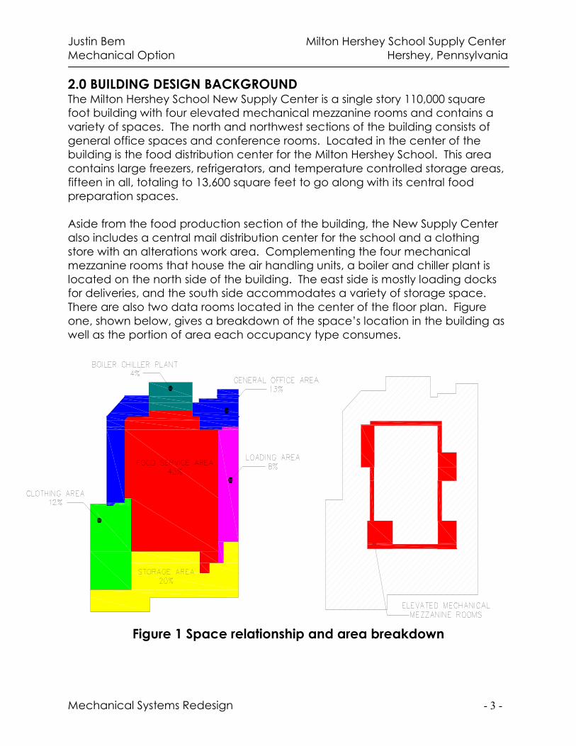
Aside from the food production section of the building, the New Supply Center
also includes a central mail distribution center for the school and a clothing
store with an alterations work area. Complementing the four mechanical
mezzanine rooms that house the air handling units, a boiler and chiller plant is
located on the north side of the building. The east side is mostly loading docks
for deliveries, and the south side accommodates a variety of storage space.
There are also two data rooms located in the center of the floor plan. Figure
one, shown below, gives a breakdown of the space’s location in the building as
well as the portion of area each occupancy type consumes.
Figure 1 Space relationship and area breakdown
Justin Bem Milton Hershey School Supply Center
Mechanical Option Hershey, Pennsylvania
Mechanical Systems Redesign - 4 -
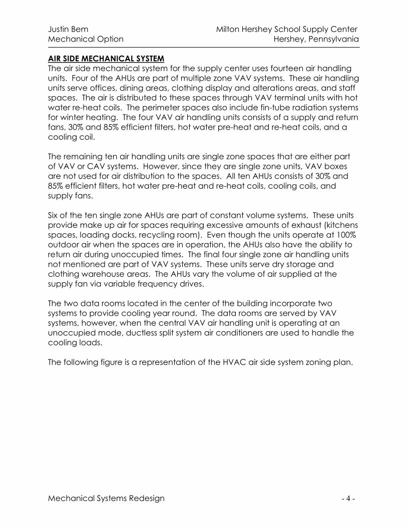
AIR SIDE MECHANICAL SYSTEM
The air side mechanical system for the supply center uses fourteen air handling
units. Four of the AHUs are part of multiple zone VAV systems. These air handling
units serve offices, dining areas, clothing display and alterations areas, and staff
spaces. The air is distributed to these spaces through VAV terminal units with hot
water re-heat coils. The perimeter spaces also include fin-tube radiation systems
for winter heating. The four VAV air handling units consists of a supply and return
fans, 30% and 85% efficient filters, hot water pre-heat and re-heat coils, and a
cooling coil.
The remaining ten air handling units are single zone spaces that are either part
of VAV or CAV systems. However, since they are single zone units, VAV boxes
are not used for air distribution to the spaces. All ten AHUs consists of 30% and
85% efficient filters, hot water pre-heat and re-heat coils, cooling coils, and
supply fans.
Six of the ten single zone AHUs are part of constant volume systems. These units
provide make up air for spaces requiring excessive amounts of exhaust (kitchens
spaces, loading docks, recycling room). Even though the units operate at 100%
outdoor air when the spaces are in operation, the AHUs also have the ability to
return air during unoccupied times. The final four single zone air handling units
not mentioned are part of VAV systems. These units serve dry storage and
clothing warehouse areas. The AHUs vary the volume of air supplied at the
supply fan via variable frequency drives.
The two data rooms located in the center of the building incorporate two
systems to provide cooling year round. The data rooms are served by VAV
systems, however, when the central VAV air handling unit is operating at an
unoccupied mode, ductless split system air conditioners are used to handle the
cooling loads.
The following figure is a representation of the HVAC air side system zoning plan.
Justin Bem Milton Hershey School Supply Center
Mechanical Option Hershey, Pennsylvania
Mechanical Systems Redesign - 5 -
Figure 2 Air side mechanical systems zoning plan
CHILLED WATER SYSTEM
The chiller plant of the supply center consists of two (one duty one standby) 270
ton electric driven centrifugal water cooled chillers that produce 45°F water.
These chillers are used to meet the normal HVAC building loads. Also included
in the chilled water system are two (one duty one standby) water cooled brine
chillers that produce 20°F water. These chillers service fan coil units located in
walk-in-coolers and refrigerated rooms year round. The two sets of chillers in the
plant are interconnected in that they all have the capabilities to produce either
45°F or 20°F water for emergency purposes. All four of the chillers operate with
R-134a refrigerant and the entire chilled water system (both the HVAC and brine
loops) are provided with a 35% propylene glycol solution.
As mentioned above, the 45°F water loop also serves two plate frame heat
exchangers to pick up the rejected heat from the walk-in freezers. The rejected
heat from the freezers is distributed to a condenser water loop. This water loop is
then cooled by the chilled water system before returning to the freezer’s
condensing units.
The HVAC chilled water loop incorporates a primary-secondary pumping
system. Three primary pumps are located in the chilled water plant and are of a
Justin Bem Milton Hershey School Supply Center
Mechanical Option Hershey, Pennsylvania
Mechanical Systems Redesign - 6 -
duty-duty-standby configuration. Two secondary pumps with VFDs distribute
chilled water to the building loop. A similar pumping configuration is used for
the brine loop, however, only four pumps are needed (2 primary, 2 secondary).
The chiller room includes a refrigerant leak detection and exhaust system that
complies with ASHRAE Standard 15.
CONDENSER WATER SYSTEM
The condenser water system for the chilled water plant includes two induced
draft cooling towers for the heat rejection equipment. These service all four of
the chiller’s condensers. The walk-in freezer’s condenser water loop also utilizes
the chiller plant’s condenser water system. As stated above, the freezer’s
rejected heat is handled by the HVAC chilled water loop. This operation occurs
in the summer months, or when the ambient outdoor temperature is above 50°F.
The freezer’s condenser water loop bypasses the plate frame heat exchangers
that are served by 45°F chilled water and enters a third plate frame heat
exchanger served directly by 60°F condensing water from the cooling tower.
This process is used for water side “free” cooling in seasons where the outdoor
temperature is below 50°F.
STEAM BOILER AND HOT WATER SYSTEMS
The boiler plant in the supply center consists of three natural gas-fired fire tube
boilers. The two larger boilers, 200 BHP, service the building HVAC heating and
domestic water heating loads. The third smaller boiler, 125 BHP, meets the
kitchen equipment hot water demands. The boilers also incorporate flue gas
recirculation to lower pollution levels. NOX levels are held to 30 parts per million
due to this configuration.
A combination deaerator and condensate storage tank is used to provide feed
water to the boilers. Three active feed water pumps operate continuously with
feed water valves located on the boilers. The feed water valves are controlled
by level sensors so that minimum water levels are met to avoid potential
hazards.
As stated above, the steam boilers produce 40 psig steam to service kitchen
equipment loads, such as dishwashers. However, hot water for HVAC heating is
also produced by these boilers. Hot water is needed to serve fin tube radiators,
VAV box reheat coils, and cabinet and horizontal unit heaters. The hot water is
produced by conversion of low pressure steam in two (one duty, one standby)
shell and tube heat exchangers. Two hot water pumps with VFDs distribute the
hot water to the HVAC equipment.
Justin Bem Milton Hershey School Supply Center
Mechanical Option Hershey, Pennsylvania
Mechanical Systems Redesign - 7 -
3.0 PROPOSAL OBJECTIVES The Milton Hershey School New Supply Center’s mechanical systems are
designed with careful attention towards energy conservation and thermal
comfort. Overall, the combination of the HVAC system’s ability to incorporate
other building systems as well as its sophisticated control methods, used to
minimize energy consumption while maintaining thermal comfort, classifies it as
very good for this application. The design engineers at H.F. Lenz Company cut
no corners in the design, however, there are still alternatives that need
addressed. Adjustments to the current design or redesign of certain areas of the
HVAC system can result in further optimization in first cost, construction cost, and
operating cost.
The goal of this mechanical system redesign is to increase energy efficiency,
decrease life cycle cost, and maintain or improve the level of thermal comfort
that the existing systems set. The original design of the supply center achieves
the status of LEED Certification. Any alterations to the mechanical system are
not to lower this standard. The final goal of the redesign is to use unique or non-
ordinary methods and systems for the study, and measure there performance in
this situation. The results from the analyses will not only prove whether the
redesign meets the project goals, but will serve as educational value to see how
these different systems react with the given conditions.
The main goal of the ones listed above is to increase energy efficiency.
Technical Assignment 2 looked at the supply center’s annual energy usage. The
results for the report indicate that the main source of energy to operate the
refrigeration equipment and AHUs is electricity, and the heating equipment
utilizes natural gas. Decreasing the amount of electricity consumed by the
HVAC equipment will significantly lower the annual energy cost to operate the
supply center. Lowering the annual energy cost will also create the potential for
decreasing the life cycle cost of the HVAC systems.
Alterations to the HVAC system may result in significant differences in first cost
compared to the existing system. The goal of this redesign is to recommend the
most energy efficient, sustainable, and cost effective system. The
recommended system must include a reasonable pay back period, about 3
years, when compared to the alternatives. Whether the existing system or the
alternatives are selected as the best, pay back periods longer than 3 to 4 years
will not justify their use in this application.
Justin Bem Milton Hershey School Supply Center
Mechanical Option Hershey, Pennsylvania
Mechanical Systems Redesign - 8 -
4.0 REDESIGN ALTERNATIVES All phases of the existing HVAC system have design alternatives that can lead to
improvements. This section examines all possible alternatives to each portion of
the supply center’s mechanical system
AIR SIDE SYSTEMS
The current method, as explained above, consists of 14 air handling units that
are part of either CAV or VAV systems. These systems do have the potential to
create humidity control problems. In order to eliminate these problems,
replacing the all-air systems with a dedicated outdoor air system (DOAS) is an
alternative. The DOAS configurations will result in a smaller quantity of required
AHUs to handle both the ventilation needs and the latent loads of the spaces.
However, since there are 6 AHUs that are constant volume make-up air units,
these units are not replaceable with DOAS.
The 6 make-up air units operate at 100% outdoor air when the spaces they
serve, the kitchen and bakery, are in operation. When the spaces are not in
use, the units operate at minimum outdoor and have the ability to return air as
well. This method of cooling these spaces makes sense from an energy
standpoint, and it meets ventilation and indoor air quality requirements.
Therefore, these air handling units should remain.
Replacing the remaining 8 AHUs with dedicated units requires the use of parallel
cooling systems. The possible parallel cooling systems include fan coil units,
chilled beams, radiant ceiling panels, and water source heat pumps. All of the
alternatives do not affect the interior architecture, and there is room above the
ceilings for these systems. The use of FCUs or WSHPs requires electricity for their
fans to operate, however, and this is a downfall. Radiant panels and chilled
beams only require the chilled water pumping energy for operation. The system
that best optimizes the building energy use and also is easily integrated with the
other building systems is to be analyzed.
CHILLER AND BOILER PLANT
The chiller plant at the supply center uses electricity for operation while the
steam boiler plant utilizes the new natural gas service installed at the building.
The natural gas service is also directly used by the kitchen equipment in the
supply center and therefore is irreplaceable. The available energy sources
create possibilities for alterations to the boiler and chiller plants.
Since natural gas is readily available at the supply center, using a direct fired
absorption chiller-heater is a chiller plant alternative. This method will decrease
the amount of electricity required for the refrigeration process, but will increase
Justin Bem Milton Hershey School Supply Center
Mechanical Option Hershey, Pennsylvania
Mechanical Systems Redesign - 9 -
the natural gas consumption. The chiller-heater will produce the appropriate
chilled water temperatures needed to handle the thermal loads in the spaces
while simultaneously producing hot water used by both the HVAC equipment
and the kitchen equipment.
The production of chilled water directly depends on the HVAC systems selected.
DOAS systems will require chilled water for dehumidification, and the
corresponding parallel systems may or may not require chilled water. Water
source heat pumps do not require the use of a chiller, just heat rejection
equipment.
5.0 PROPOSED REDESIGN The design alternatives and methods are now explained in the above section.
The mechanical system redesign proposal for the supply center is laid out in this
section. The proposal design objectives are integrated with the existing building
conditions as well as the design alternatives to create a potential energy
efficient, sustainable HVAC system.
DOAS AND HEAT PUMP SYSTEM
Dedicated outdoor air systems are proposed to replace the air handling units
that service general office spaces, clothing spaces, the mail room, and the
locker rooms. The goal of using DOAS is to decrease the number of AHUs
needed, improve energy efficiency, and improve indoor air quality. Using DOAS
requires a parallel system to handle the remaining thermal loads in the spaces.
The proposed system will incorporate water source heat pumps as the parallel
cooling and heating system.
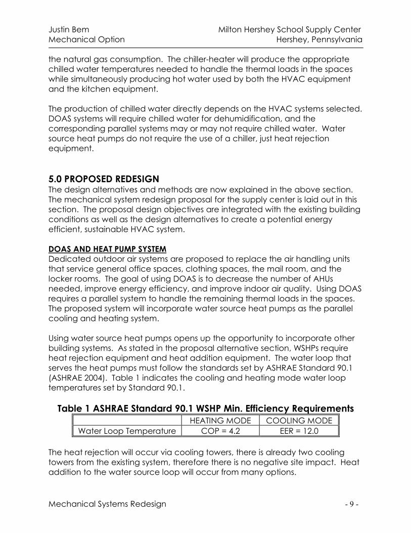
Using water source heat pumps opens up the opportunity to incorporate other
building systems. As stated in the proposal alternative section, WSHPs require
heat rejection equipment and heat addition equipment. The water loop that
serves the heat pumps must follow the standards set by ASHRAE Standard 90.1
(ASHRAE 2004). Table 1 indicates the cooling and heating mode water loop
temperatures set by Standard 90.1.
Table 1 ASHRAE Standard 90.1 WSHP Min. Efficiency Requirements
HEATING MODE COOLING MODE
Water Loop Temperature COP = 4.2 EER = 12.0
The heat rejection will occur via cooling towers, there is already two cooling
towers from the existing system, therefore there is no negative site impact. Heat
addition to the water source loop will occur from many options.
Justin Bem Milton Hershey School Supply Center
Mechanical Option Hershey, Pennsylvania
Mechanical Systems Redesign - 10 -
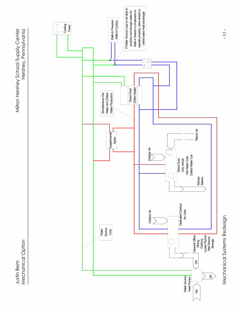
The simplest way for heat addition to the water source loop is by adding a
supplemental hot water boiler. However, incorporating the other HVAC and
building systems is one of the major proposal goals. Heat addition to the water
loop can occur from picking up the rejected heat from the walk-in freezer’s and
walk-in cooler’s condensing units. This will occur when the condenser water
temperature returned to the units is lower enough to properly create the
needed supply temperatures. When heat rejection to the water source loop is
not sufficient to operate the freezers correctly, the condenser water loop will by
pass the heat pump source loop and will reject heat directly to a chilled water
loop as in the original system. Appendix A shows a schematic of this redesign
and illustrates this system more clearly.
Even though chillers are not needed in water source heat pump systems, there
are parts in the proposed HVAC system that still requires chilled water. Chillers
are needed to supply chilled water to the DOAS and make-up AHUs. Since
these chillers are a necessity, a plate frame heat exchanger that is currently in
the existing system will pick up the rejected heat from the walk-in freezers when
the water source loop can not. The chiller’s condenser water system now has
the potential for integration with the water source loop.
The rejected heat from the chillers will be added to the water source loop.
Since the water source loop is directly connected to the cooling towers, when
the loop becomes too hot for operation, the cooling towers will operate to
maintain the loop temperature. The preliminary schematic shown in Appendix A
further illustrates this point.
CHILLER-HEATER SYSTEM
The chiller-heater will not only produce the chilled water needed for HVAC
cooling, but will also simultaneously produce domestic hot water. There is also
potential for the hot water production to be added to the water source loop to
help maintain the cooling mode temperature. The heat pump system is also to
be modeled with electric chillers, such as the existing centrifugal chillers.
Comparisons between using the heat pump system in conjunction with electric
driven water cooled chillers or with steam driven absorption chiller-heaters will
lead way for recommending the best overall system. The entire DOAS/heat
pump system plus chiller plant redesign must be compared to the original
system as well, especially to calculate pay back periods. The best overall
system will include a reasonable first cost, low operating costs, and a
manageable pay back period when compared to the alternatives.
Ju
stin
Be
m
M
ilto
n H
ers
he
y S
ch
oo
l Su
pp
ly C
en
ter
Me
ch
an
ica
l O
ptio
n
H
ers
he
y, P
en
nsy
lva
nia
Me
ch
an
ica
l Syst
em
s R
ed
esi
gn
- 11 -
Direct Fired
Chiller-Heater
Simultaneous Hot
Water and Chilled
Water Production
Kitchen
Bakery
Outdoor Air
Return Air
Supplemental
Boiler
Outdoor Air
General Office
Dining
Clothing
Locker Rooms
Mail Rooms
Storage
RA
OA
SA
Cooling
Tower
Walk-In Freezers
Walk-In Coolers
Water
Source
Loop
If Water Source Loop is not able to
produce cool enough water for
Walk-in freezer’s condensers to
operate properly, valve diverts to
chilled water heat exchanger
Direct Fired
CAV AHUS
Hot Water Coils
Chilled Water Coil
Dedicated Outdoor
Air Units
Water Source
Heat Pumps
Justin Bem Milton Hershey School Supply Center
Mechanical Option Hershey, Pennsylvania
Mechanical Systems Redesign - 12 -
6.0 BREADTH PROPOSALS The redesign of the mechanical systems of the supply center directly affects
other building systems. Integrating the changes to the HVAC systems with
alterations to the structural system is the goal of this part of the proposal. The
breadth studies will include structural work as well as construction management
work. The overall idea is to fully incorporate all areas that play a direct or
indirect factor in the mechanical systems redesign. Improving the other systems
in terms of first cost is also an important goal of the project.
STRUCTURAL PROPOSAL
The reduction in the required amount of AHUs due to the proposed dedicated
systems opens up other opportunities. Currently there are 14 air handling units
total and they are all located in the elevated mechanical mezzanine rooms.
Since the supply center is a single story 110,000 square foot building, there is
plenty of open roof space. Reducing the amount of air handling units makes it
possible to place the equipment on the roof. The smaller number of units results
in each of them being fully accessible on the roof. However, a significant dead
load and live load will occur from placing the units on the roof that affects the
structural system. The structural breadth is to study the affect of relocating the
AHUs and make the appropriate changes to the structural system. The cost
difference, if any, will needed justification. Comparing the potential additional
cost of increasing structural members to the potential cost saving from the
mechanical redesign will help prove, overall, if the new systems are
economically feasible.
CONSTRUCTION PROPOSAL
Replacing eight AHUs with fewer dedicated outdoor air units opens up the
opportunity to move all of the AHUs to the roof and eliminate the elevated
mechanical mezzanine rooms. However, as previously stated, this move affects
the structural system and also affects the overall building cost. The construction
breadth of the proposal will examine the cost of constructing the steel
mezzanine rooms and compare it to the cost of increasing the structural
members that is needed to support the added dead loads. The cost of outdoor
ready AHUs are also more expensive than indoor AHUs. The cost difference must
also be justified by the elimination of the mezzanine rooms. The construction
breadth will also help to further justify the recommended mechanical system
redesign with detailed cost estimates.
ELECTRICAL PROPOSAL
The proposed mechanical redesign includes the replacement of electric driven
centrifugal chillers with natural gas fired absorption chiller-heaters. Therefore, a
significant electrical change will ocurre dealing with the main distribution system
as well as the mechanical room panel boards.
Justin Bem Milton Hershey School Supply Center
Mechanical Option Hershey, Pennsylvania
Mechanical Systems Redesign - 13 -
7.0 PROJECT METHODS There are many engineer tools that are needed for execution of the thesis
project. Taking full advantage of engineering software for calculations and
using spread sheets for further calculations and organization will help the project
run smoothly.
MECHANICAL DEPTH
Using Carrier’s Hourly Analysis Program (HAP) for calculating space loads is the
first step in the project. The program also can calculate annual energy usage
from all AHUs and water source heat pumps. Using that load and energy data,
the Engineering Equation Solver (EES) will further analyze the remainder of the
redesign.
A chiller-heater model, set up in EES, will help calculate the annual energy
consumption for refrigeration and domestic hot water heating processes. The
model also will calculate the amount of steam needed to perform these tasks,
which will then result in the calculation of natural gas consumption.
Incorporating each major piece of equipment to the EES program is the key for
the analysis. The walk-in refrigeration equipment, water source heat pumps, the
Chiller-heater, the supplemental boilers, the steam boilers, the AHUs, the cooling
towers, and all associated pumps and fans will, when properly written into the
program, give a good annual cost of operation estimate.
As stated above, the loads for each space handled by the HVAC equipment is
calculated using HAP. Therefore, these numbers will help calculate leaving and
entering source water temperatures. The EES program will regulate the source
water loop temperature and appropriate functions will indicate when the
cooling towers must operate or when certain items must by-pass the water loop.
Once all energy consumption data is found, EES or Excel will convert the energy
values to cost using the site’s utility rates.
BREADTH WORK
Structural analysis and steel design methods will be used for completion of the
breadth work. For generating cost, R.S. Means along with cost from
manufactures will provide realistic, accurate values. Excel spread sheets will
serve as a major organization tool as well as perform many calculations. Life
cycle cost calculations are easily performed in Excel. Structural take-offs for
detailed cost estimates are also made easier with use of Excel.
8.0 CONCLUSIONS The Milton Hershey School New Supply Center has a very involved, energy
conscience mechanical system. There is room for improvement, however, and
Justin Bem Milton Hershey School Supply Center
Mechanical Option Hershey, Pennsylvania
Mechanical Systems Redesign - 14 -
the proposed systems hope to find areas in the design that save cost and
energy. While the supply center’s existing conditions are good for this
application, the goal of this redesign is to gain knowledge and experience.
Understanding and evaluating the capabilities of systems, like DOAS and heat
pumps, when applied to another type of building (in this case a supply center) is
the main purpose of the proposed thesis.
9.0 PRELIMINARY RESEARCH The following sources were used for preliminary research on the topics stated
above.
ASHRAE, 2005 ASHRAE Handbook – Fundamentals. American Society of Heating
Refrigeration and Air Conditioning Engineers, Inc., Atlanta, GA. 2001.
ASHRAE, ANSI/ASHRAE, Standard 90.1 – 2004, Energy Standard for Buildings
Except Low-Rise Residential Buildings. American Society of Heating Refrigeration
and Air Conditioning Engineers, Inc., Atlanta, GA. 2004.
Bahnfleth, William P, PhD, PE, Thies, Roger M. Gas-Fired Chiller-Heaters as a
Central Plant Alternative for Small Office Buildings. HPAC Engineering. January
1998.
McQuay Water Source Heat Pump Literature, Retrieved February, 2006 from
http://www.mcquay.com/ McQuay/ProductInformation/WSHP/WSHPpage
McQuay SANO Absorption Chiller-Heater Operation and Maintenance Data,
Retrieved November, 2006 from http://www.mcquay.com/mcquaybiz/literature
/lit_ch_wc/IMOM/Om114.pdf
R.S. Means, Mechanical Cost Data, 28th Annual Edition. R.S. Means, Kingston,
MA. 2005.
Justin Bem Milton Hershey School Supply Center
Mechanical Option Hershey, Pennsylvania
Mechanical Systems Redesign - 15 -
10.0 REFERENCES
ASHRAE. 2005, 2005 ASHRAE Handbook – Fundamentals. American Society of
Heating Refrigeration and Air Conditioning Engineers, Inc., Atlanta, GA. 2001.
ASHRAE. 2004, ANSI/ASHRAE, Standard 90.1 – 2004, Energy Standard for Buildings
Except Low-Rise Residential Buildings. American Society of Heating Refrigeration
and Air Conditioning Engineers, Inc., Atlanta, GA. 2004.
Bahnfleth, William P, PhD, PE, Thies, Roger M. Gas-Fired Chiller-Heaters as a
Central Plant Alternative for Small Office Buildings. HPAC Engineering. January
1998.
Bem, Justin S. Technical Assignment 1: ASHRAE Standard 62.1 Ventilation
Compliance Evaluation of the Milton Hershey School New Supply Center.
October 4th, 2006.
Bem, Justin S. Technical Assignment 2: Building and Plant Energy Analysis Report
of the Milton Hershey School New Supply Center. October 27th, 2006.
Bem, Justin S. Technical Assignment 3: Mechanical Systems Existing Conditions
Evaluation of the Milton Hershey School New Supply Center. November 21st,
2006.
McQuay SANO Absorption Chiller-Heater Operation and Maintenance Data,
Retrieved November, 2006 from http://www.mcquay.com/mcquaybiz/literature
/lit_ch_wc/IMOM/Om114.pdf
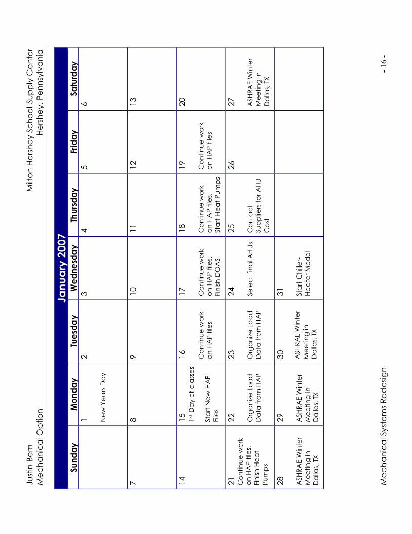
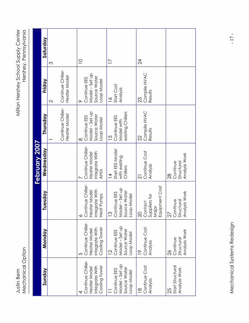
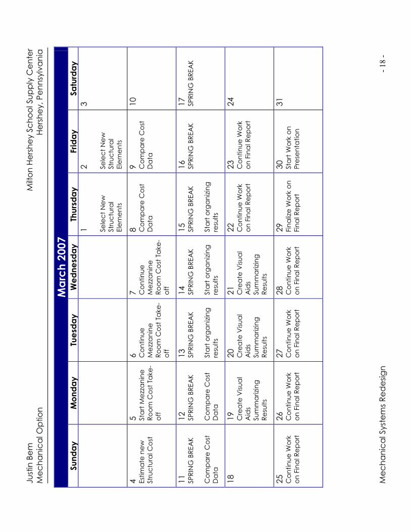
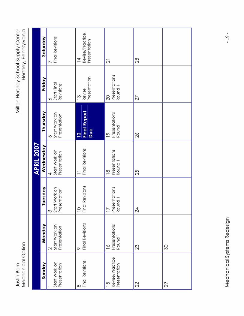
11.0 Schedules A calendar of the spring 2007 semester at The Pennsylvania State University is
used for setting completion milestones and schedules for work on the proposed
mechanical systems redesign.
Ju
stin
Be
m
M
ilto
n H
ers
he
y S
ch
oo
l Su
pp
ly C
en
ter
Me
ch
an
ica
l O
ptio
n
H
ers
he
y, P
en
nsy
lva
nia
Me
ch
an
ica
l Syst
em
s R
ed
esi
gn
- 16 -
January
2007
Sunday
Monday
Tuesd
ay
Wednesd
ay
Thursday
Friday
Satu
rday
1
Ne
w Y
ea
rs D
ay
2
3
4
5
6
7
8
9
10
11
12
13
14
15
1ST
Da
y o
f c
lass
es
Sta
rt N
ew
HA
P
File
s
16
Co
ntin
ue
wo
rk
on
HA
P f
iles
17
Co
ntin
ue
wo
rk
on
HA
P f
iles,
Fin
ish
DO
AS
18
Co
ntin
ue
wo
rk
on
HA
P f
iles,
Sta
rt H
ea
t P
um
ps
19
Co
ntin
ue
wo
rk
on
HA
P f
iles
20
21
Co
ntin
ue
wo
rk
on
HA
P f
iles,
Fin
ish
He
at
Pu
mp
s
22
Org
an
ize
Lo
ad
Da
ta f
rom
HA
P
23
Org
an
ize
Lo
ad
Da
ta f
rom
HA
P
24
Se
lec
t fin
al A
HU
s
25
Co
nta
ct
Su
pp
liers
fo
r A
HU
Co
st
26
27
ASH
RA
E W
inte
r
Me
etin
g in
Da
llas,
TX
28
ASH
RA
E W
inte
r
Me
etin
g in
Da
llas,
TX
29
ASH
RA
E W
inte
r
Me
etin
g in
Da
llas,
TX
30
ASH
RA
E W
inte
r
Me
etin
g in
Da
llas,
TX
31
Sta
rt C
hill
er-
He
ate
r M
od
el
Ju
stin
Be
m
M
ilto
n H
ers
he
y S
ch
oo
l Su
pp
ly C
en
ter
Me
ch
an
ica
l O
ptio
n
H
ers
he
y, P
en
nsy
lva
nia
Me
ch
an
ica
l Syst
em
s R
ed
esi
gn
- 17 -
Febru
ary
2007
Sunday
Monday
Tuesd
ay
Wednesd
ay
Thursday
Friday
Satu
rday
1
Co
ntin
ue
Ch
ille
r-
He
ate
r M
od
el
2
Co
ntin
ue
Ch
ille
r-
He
ate
r M
od
el
3
4
Co
ntin
ue
Ch
ille
r-
He
ate
r M
od
el
Inte
gra
te W
ith
Co
olin
g T
ow
er
5
Co
ntin
ue
Ch
ille
r-
He
ate
r M
od
el
Inte
gra
te W
ith
Co
olin
g T
ow
er
6
Co
ntin
ue
Ch
ille
r-
He
ate
r M
od
el
Inte
gra
te W
ith
He
at
Pu
mp
s
7
Co
ntin
ue
Ch
ille
r-
He
ate
r M
od
el
Inte
gra
te W
ith
AH
Us
8
Co
ntin
ue
EES
Mo
de
l – S
et
up
So
urc
e W
ate
r
Loo
p M
od
el
9
Co
ntin
ue
EES
Mo
de
l – S
et
up
So
urc
e W
ate
r
Loo
p M
od
el
10
11
Co
ntin
ue
EES
Mo
de
l – S
et
up
So
urc
e W
ate
r
Loo
p M
od
el
12
Co
ntin
ue
EES
Mo
de
l – S
et
up
So
urc
e W
ate
r
Loo
p M
od
el
13
Co
ntin
ue
EES
Mo
de
l – S
et
up
So
urc
e W
ate
r
Loo
p M
od
el
14
Sta
rt E
ES M
od
el
with
exis
tin
g
Ch
ille
rs
15
Co
ntin
ue
EES
Mo
de
l w
ith
exis
tin
g C
hill
ers
16
Sta
rt C
ost
An
aly
sis
17
18
Co
ntin
ue
Co
st
An
aly
sis
19
Co
ntin
ue
Co
st
An
aly
sis
20
Co
nta
ct
Su
pp
liers
fo
r
Ma
jor
Eq
uip
me
nt
Co
st
21
Co
ntin
ue
Co
st
An
aly
sis
22
Co
mp
ile H
VA
C
Re
sults
23
Co
mp
ile H
VA
C
Re
sults
24
25
Sta
rt S
tru
ctu
ral
An
aly
sis
Wo
rk
26
Co
ntin
ue
Str
uc
tura
l
An
aly
sis
Wo
rk
27
Co
ntin
ue
Str
uc
tura
l
An
aly
sis
Wo
rk
28
Co
ntin
ue
Str
uc
tura
l
An
aly
sis
Wo
rk
Ju
stin
Be
m
M
ilto
n H
ers
he
y S
ch
oo
l Su
pp
ly C
en
ter
Me
ch
an
ica
l O
ptio
n
H
ers
he
y, P
en
nsy
lva
nia
Me
ch
an
ica
l Syst
em
s R
ed
esi
gn
- 18 -
Marc
h 2007
Sunday
Monday
Tuesd
ay
Wednesd
ay
Thursday
Friday
Satu
rday
1
Se
lec
t N
ew
Str
uc
tura
l
Ele
me
nts
2
Se
lec
t N
ew
Str
uc
tura
l
Ele
me
nts
3
4
Est
ima
te n
ew
Str
uc
tura
l C
ost
5
Sta
rt M
ezz
an
ine
Ro
om
Co
st T
ake
-
off
6
Co
ntin
ue
Me
zza
nin
e
Ro
om
Co
st T
ake
-
off
7
Co
ntin
ue
Me
zza
nin
e
Ro
om
Co
st T
ake
-
off
8
Co
mp
are
Co
st
Da
ta
9
Co
mp
are
Co
st
Da
ta
10
11
SP
RIN
G B
REA
K
Co
mp
are
Co
st
Da
ta
12
SP
RIN
G B
REA
K
Co
mp
are
Co
st
Da
ta
13
SP
RIN
G B
REA
K
Sta
rt o
rga
niz
ing
resu
lts
14
SP
RIN
G B
REA
K
Sta
rt o
rga
niz
ing
resu
lts
15
SP
RIN
G B
REA
K
Sta
rt o
rga
niz
ing
resu
lts
16
SP
RIN
G B
REA
K
17
SP
RIN
G B
REA
K
18
19
Cre
ate
Vis
ua
l
Aid
s
Su
mm
arizi
ng
Re
sults
20
Cre
ate
Vis
ua
l
Aid
s
Su
mm
arizi
ng
Re
sults
21
Cre
ate
Vis
ua
l
Aid
s
Su
mm
arizi
ng
Re
sults
22
Co
ntin
ue
Wo
rk
on
Fin
al R
ep
ort
23
Co
ntin
ue
Wo
rk
on
Fin
al R
ep
ort
24
25
Co
ntin
ue
Wo
rk
on
Fin
al R
ep
ort
26
Co
ntin
ue
Wo
rk
on
Fin
al R
ep
ort
27
Co
ntin
ue
Wo
rk
on
Fin
al R
ep
ort
28
Co
ntin
ue
Wo
rk
on
Fin
al R
ep
ort
29
Fin
aliz
e W
ork
on
Fin
al R
ep
ort
30
Sta
rt W
ork
on
Pre
sen
tatio
n
31
Ju
stin
Be
m
M
ilto
n H
ers
he
y S
ch
oo
l Su
pp
ly C
en
ter
Me
ch
an
ica
l O
ptio
n
H
ers
he
y, P
en
nsy
lva
nia
Me
ch
an
ica
l Syst
em
s R
ed
esi
gn
- 19 -
APRIL 2007
Sunday
Monday
Tuesd
ay
Wednesd
ay
Thursday
Friday
Satu
rday
1
Sta
rt W
ork
on
Pre
sen
tatio
n
2
Sta
rt W
ork
on
Pre
sen
tatio
n
3
Sta
rt W
ork
on
Pre
sen
tatio
n
4
Sta
rt W
ork
on
Pre
sen
tatio
n
5
Sta
rt W
ork
on
Pre
sen
tatio
n
6
Sta
rt F
ina
l
Re
vis
ion
s
7
Fin
al R
evis
ion
s
8
Fin
al R
evis
ion
s 9
Fin
al R
evis
ion
s 10
Fin
al R
evis
ion
s 11
Fin
al R
evis
ion
s 12
Final Report
Due
13
Re
vis
e
Pre
sen
tatio
n
14
Re
vis
e/P
rac
tic
e
Pre
sen
tatio
n
15
Re
vis
e/P
rac
tic
e
Pre
sen
tatio
n
16
Pre
sen
tatio
ns
Ro
un
d 1
17
Pre
sen
tatio
ns
Ro
un
d 1
18
Pre
sen
tatio
ns
Ro
un
d 1
19
Pre
sen
tatio
ns
Ro
un
d 1
20
Pre
sen
tatio
ns
Ro
un
d 1
21
22
23
24
25
26
27
28
29
30