
Thermostatic radiator valves for NPT threaded radiators ... · Thermostatic radiator valves for NPT...
6
CALEFFI ACCREDITED ISO 9001 No. 0003 ISO 9001 FM 21654 Thermostatic radiator valves for NPT threaded radiators 220 series 01034/13 NA Function Thermostatic valves are typically used for controlling the fluid flow to the radiators of hydronic heating systems. They are composed of two parts: a control head and valve body. The control contains a liquid-filled thermostatic element that automatically controls the opening of the valve to maintain room temperature at the set value. This prevents unwanted room temperature rises, providing considerable energy savings. The valve body has NPT threaded connections: female threads to connect to the system and union male threads to connect to the radiator. These valves can also be used for isolating and balancing. Product range VALVES: 220 series Angled thermostatic radiator valve body ........................................................connections 1/2", 3/4" 221 series Straight thermostatic radiator valve body .......................................................connections 1/2", 3/4" THERMOSTATIC CONTROL HEADS: 200 series Thermostatic control head, built-in sensor with liquid-filled element ......... graduated scale *–5 corresponding to 45–82°F (7–28°C) 201 series Thermostatic control head, remote sensor with liquid-filled element ........ graduated scale *–5 corresponding to 45–82°F (7–28°C) 203 series Thermostatic control head with contact probe ....................................... graduated scale 68–122°F (20–50°C) 472 series Thermostatic control head with remote adjusting knob, liquid-filled element ....graduated scale *–5 corresponding to 43–82°F (6–28°C) Technical specification of valve bodies Materials - body: brass chrome plated - valve control stem: stainless steel - seals: EPDM - control knob and cap: ABS (RAL 9010) Performance Suitable fluids: water, glycol solutions Max. percentage of glycol: 30% Max. differential pressure assembled with control head: 15 psi (1 bar) Max. working pressure: 150 psi (10 bar) Temperature range: 40–212°F (5–100°C) Technical specification of control heads 200/201 series Scale of adjustment: *–5 Setting temperature range: 45–82°F (7–28°C) Frost protection cut-in: 45°F (7°C) Max. ambient temperature: 120°F (50°C) Length of capillary, 201 series: 78" (2m) Approval: In compliance with EN 215 (KEYMARK) Thermostatic Efficiency Label (TELL): Lev. A, Reg. 10428/9-20110527 Control adjustment scale, 200/201 series 0 * 1 2 3 4 5 32°F 45°F 55°F 60°F 68°F 75°F 82°F 0°C 7°C 12°C 16°C 20°C 24°C 28°C Technical specification of control heads 203 series Setting temperature range: - code 203502 68–122°F (20–50°C) Max. sensor temperature: 212°F (100°C) Max. pocket pressure: 150 psi (10 bar) Length of capillary: 78" (2m) Control adjustment scale, 203 series 68°F 75°F 85°F 95°F 105°F 110°F 122°F 20°C 25°C 30°C 35°C 40°C 45°C 50°C Technical specification of control heads 472 series Scale of adjustment: 0–5 Setting temperature range: - code 47200 43–82°F (6–28°C) Frost protection cut-in: 43°F (6°C) Accuracy: ±0.7°F (0.4°C) Max. sensor temperature: 120°F (50°C) Length of capillary: 78" (2m) Control adjustment scale, 472 series 0 * 1 2 3 4 5 32°F 43°F 54°F 61°F 68°F 75°F 82°F 0°C 6°C 12°C 16°C 20°C 24°C 28°C 028
-
Upload
vuongthuan -
Category
Documents
-
view
237 -
download
0
Transcript of Thermostatic radiator valves for NPT threaded radiators ... · Thermostatic radiator valves for NPT...

CALEFFIACCREDITED
ISO 9001 No. 0003ISO 9001 FM 21654
Thermostatic radiator valves for NPT threaded radiators220 series
01034/13 NA
Function
Thermostatic valves are typically used for controlling the fluid flow to the radiators of hydronic heating systems. They are composed of two parts: a control head and valve body.
The control contains a liquid-filled thermostatic element that automatically controls the opening of the valve to maintain room temperature at the set value. This prevents unwanted room temperature rises, providing considerable energy savings.
The valve body has NPT threaded connections: female threads to connect to the system and union male threads to connect to the radiator. These valves can also be used for isolating and balancing.
Product range
VALVES:220 series Angled thermostatic radiator valve body . . . . . . . . . . . . . . . . . . . . . . . . . . . . . . . . . . . . . . . . . . . . . . . . . . . . . . . .connections 1/2", 3/4"221 series Straight thermostatic radiator valve body . . . . . . . . . . . . . . . . . . . . . . . . . . . . . . . . . . . . . . . . . . . . . . . . . . . . . . .connections 1/2", 3/4"
THERMOSTATIC CONTROL HEADS:200 series Thermostatic control head, built-in sensor with liquid-filled element . . . . . . . . . graduated scale *–5 corresponding to 45–82°F (7–28°C)201 series Thermostatic control head, remote sensor with liquid-filled element . . . . . . . . graduated scale *–5 corresponding to 45–82°F (7–28°C)203 series Thermostatic control head with contact probe . . . . . . . . . . . . . . . . . . . . . . . . . . . . . . . . . . . . . . . graduated scale 68–122°F (20–50°C)472 series Thermostatic control head with remote adjusting knob, liquid-filled element . . . .graduated scale *–5 corresponding to 43–82°F (6–28°C)
Technical specification of valve bodies
Materials - body: brass chrome plated - valve control stem: stainless steel - seals: EPDM - control knob and cap: ABS (RAL 9010)
PerformanceSuitable fluids: water, glycol solutionsMax. percentage of glycol: 30%Max. differential pressure assembled with control head: 15 psi (1 bar)Max. working pressure: 150 psi (10 bar)Temperature range: 40–212°F (5–100°C)
Technical specification of control heads 200/201 seriesScale of adjustment: *–5Setting temperature range: 45–82°F (7–28°C)Frost protection cut-in: 45°F (7°C)Max. ambient temperature: 120°F (50°C)Length of capillary, 201 series: 78" (2m)Approval:In compliance with EN 215 (KEYMARK)Thermostatic Efficiency Label (TELL): Lev. A, Reg. 10428/9-20110527
Control adjustment scale, 200/201 series
0 * 1 2 3 4 5
32°F 45°F 55°F 60°F 68°F 75°F 82°F 0°C 7°C 12°C 16°C 20°C 24°C 28°C
Technical specification of control heads 203 seriesSetting temperature range: - code 203502 68–122°F (20–50°C)Max. sensor temperature: 212°F (100°C)Max. pocket pressure: 150 psi (10 bar)Length of capillary: 78" (2 m)
Control adjustment scale, 203 series
68°F 75°F 85°F 95°F 105°F 110°F 122°F
20°C 25°C 30°C 35°C 40°C 45°C 50°CTechnical specification of control heads 472 seriesScale of adjustment: 0–5Setting temperature range: - code 47200 43–82°F (6–28°C)Frost protection cut-in: 43°F (6°C)Accuracy: ±0.7°F (0.4°C)Max. sensor temperature: 120°F (50°C)Length of capillary: 78" (2 m)
Control adjustment scale, 472 series
0 * 1 2 3 4 5
32°F 43°F 54°F 61°F 68°F 75°F 82°F 0°C 6°C 12°C 16°C 20°C 24°C 28°C
028

C
A
FB
D
4 3· · · · · · 2
E
C
A
EF
BD
4 3· · · · · · 2
4 3· · · · · · 2B
A
C
4 3· · · · · · 2B
A
C
D
E
4 3· · · · · · 2B
A
C
E
D
A
B
C
D
C
A
FB
D
4 3· · · · · · 2
E
C
A
EF
BD
4 3· · · · · · 2
4 3· · · · · · 2B
A
C
4 3· · · · · · 2B
A
C
DE
4 3· · · · · · 2B
A
C
E
D
A
B
C
D
C
A
FB
D
4 3· · · · · · 2
E
C
A
EF
BD
4 3· · · · · · 2
4 3· · · · · · 2B
A
C
4 3· · · · · · 2B
A
C
D
E
4 3· · · · · · 2B
A
C
E
D
A
B
C
D
C
A
FB
D
4 3· · · · · · 2
E
C
A
EF
BD
4 3· · · · · · 2
4 3· · · · · · 2B
A
C
4 3· · · · · · 2B
A
C
D
E
4 3· · · · · · 2B
A
C
E
D
A
B
C
D
Dimensions
Code A B C D E F
220400A + 200000 1⁄2" NPT 1⁄2" NPT 2" 11⁄16" 1" 4"
220500A + 200000 3⁄4" NPT 3⁄4" NPT 2" 21⁄2" 1" 4"
Code A B C D E F
221400A + 200000 1⁄2" NPT 1⁄2" NPT 2" 11⁄16" 11⁄8" 41⁄2"
221500A + 200000 3⁄4" NPT 3⁄4" NPT 2" 21⁄2" 13⁄8" 41⁄2"
Code A B C
200000 M30 x 1.5 31⁄8" 2"
Code A B C D E
201000 M30 x 1.5 31⁄8" 2" 11⁄8" 33⁄4"

C
A
FB
D
4 3· · · · · · 2
E
C
A
EF
BD
4 3· · · · · · 2
4 3· · · · · · 2B
A
C
4 3· · · · · · 2B
A
C
D
E
4 3· · · · · · 2B
A
C
E
D
A
B
C
D
Supporting surface
C
A
B
C
A
FB
D
4 3· · · · · · 2
E
C
A
EF
BD
4 3· · · · · · 2
4 3· · · · · · 2B
A
C
4 3· · · · · · 2B
A
C
D
E
4 3· · · · · · 2B
A
C
E
D
A
B
C
D
Code A B C D
NA475002 3⁄4" NPT male Ø 1⁄2" 73⁄8" 15⁄32"
Code A B C D E
203502 M30 x 1.5 31⁄8" 2" Ø 7⁄16" 61⁄4"
Code A B C
472000 23⁄8" 31⁄8" 31⁄8"

30(kPa)
20
10
5
2
1
0.5
0.20.1
1/2" 3/4"
1/2" 3/4"
∆p 107
3.5
1.6
.7
.35
.16
.07
.03
(4.35)(3)
(1.5)
(.7)
(.3)
(.15)
(.07)
(.03)
(.015)
ft of hd (psi)∆p
(.22)
(.44)
(.88)
(.08)
(.04)
(2.2
)
(4.4
)
(8.8
)
.013
.028
.055
.005
.002 .1
4
.28
.55 Flow
rate
l/s (g
pm)
30(kPa)
20
10
5
2
1
0.5
0.20.1
∆p 107
3.5
1.6
.7
.35
.16
.07
.03
(4.35)(3)
(1.5)
(.7)
(.3)
(.15)
(.07)
(.03)
(.015)
ft of hd (psi)∆p
(.22)
(.44)
(.88)
(.08)
(.04)
(2.2
)
(4.4
)
(8.8
)
.013
.028
.055
.005
.002 .1
4
.28
.55 Flow
rate
l/s (g
pm)
Flow rates at 2°F Proportional band*
Flow rates at 4°F Proportional band*
*Proportional band is the difference between the thermostaticradiator valve control head setting and the actual room temperature.
Cv: size 1", 10size 1-1/4", 14
30(kPa)
20
10
5
2
1
0.5
0.20.1
1/2" 3/4"
1/2" 3/4"
∆p 107
3.5
1.6
.7
.35
.16
.07
.03
(4.35)(3)
(1.5)
(.7)
(.3)
(.15)
(.07)
(.03)
(.015)
ft of hd (psi)∆p
(.22)
(.44)
(.88)
(.08)
(.04)
(2.2
)
(4.4
)
(8.8
)
.013
.028
.055
.005
.002 .1
4
.28
.55 Flow
rate
l/s (g
pm)
30(kPa)
20
10
5
2
1
0.5
0.20.1
∆p 107
3.5
1.6
.7
.35
.16
.07
.03
(4.35)(3)
(1.5)
(.7)
(.3)
(.15)
(.07)
(.03)
(.015)
ft of hd (psi)∆p
(.22)
(.44)
(.88)
(.08)
(.04)
(2.2
)
(4.4
)
(8.8
)
.013
.028
.055
.005
.002 .1
4
.28
.55 Flow
rate
l/s (g
pm)
Flow rates at 2°F Proportional band*
Flow rates at 4°F Proportional band*
*Proportional band is the difference between the thermostaticradiator valve control head setting and the actual room temperature.
Cv: size 1", 10size 1-1/4", 14
1
2
4
3
3 42
Valve closed
3 42
Valve open
Principle of Operation
The thermostat ic control head is a proport ional temperature control ler, con ta in ing a l i qu id - f i l l ed be l l ows thermostatic sensor.
The valve plug is normally in the (1) spring-to-open (normally open) position without the control head, or when the control head is in the maximum open position (setting 5). Under operation the ambient room temperature of air passing around the sensor rises causing the liquid in the bellows to expand, pushing the valve control stem down against the return spring. This closes the valve, reducing fluid flow to the radiator to cool the room, in proportion to the deviation from the desired temperature setting. When the room temperature decreases, the reverse occurs; the bellows contracts, which in turn allows the valve spring to open the valve, increasing the fluid flow to the radiator to warm the room.
The valve control stem (2) is stainless steel with an EPDM o-ring double seal.
This allows for replacement of the control head (3) even with the system operating. The valve plug (4) is shaped to provide an optimal flow characteristic throughout the opening and closing stroke under proportional thermostatic operation. The wide passageway between the seat and the valve plug causes reduced head losses in manual operation.
The Caleffi 200 series thermostatic control head features an exclusive liquid-filled element, liquid being an incompressible fluid. As a result, the 220 and 221 series valve bodies utilize a very strong return spring. This ensures that after a long 'off-season', when the actuator operates for the first time, the spring reliably lifts the plug seal off the seat without sticking.
The Caleffi 220 and 221 series can also be used for isolation and balancing and can be adjusted to either shutoff (isolation) or modulate flow (balancing) with either the stardard cap or with optional code 449010 manual knob.
Valves with angled connections
Code SizeCv
Proportional band (°F)
2 2.7 4 5.4 Cv Max.
220400A 1⁄2" 0.4 0.6 0.7 1.0 2.8
220500A 3⁄4" 0.5 0.7 0.9 1.3 3.7
Valves with straight connections
Code SizeCv
Proportional band (°F)
2 2.7 4 5.4 Cv Max.
221400A 1/2" 0.4 0.6 0.8 1.0 1.7
221500A 3/4" 0.5 0.7 0.95 1.2 2.6
Cv = Volume flow in gpm producing pressure drop 1 psi
Cv Max. = Cv with valve totally open
*CertificationsCaleffi valves 220, 221 series sizes ½" and ¾", in combination with control heads 200 and 201 series, are approved to standard EN 215.
Hydraulic charateristics
Thermostatic valves with angled connections 220 series and straight connections 221 series with thermostatic control head 200 or 201 series*
* Proportional band is the difference between the thermostatic radiator valve control head setting and the actual room temperature.

CALEFFI
12
3
4
CALEFFI
12
3
4
12
3
4
12
3
4
CALEFFI
60"
4"
Installation
Thermostatic control heads should be installed in the horizontal position.
The sensitive element of the thermostatic control head must not be installed in niches, alcoves, behind curtains or directly exposed to sunlight, any of which would sense incorrect temperature values.
Before install ing the thermostatic control head, turn the control knob to the number 5 position.
Locking and restricting the thermostat control temperature
Temperature restriction
Locking the temperature
Resetting the temperature restriction and temperature lock
Remote sensor control
Re fe r t o t he d imens ions shown to properly install the thermostatic control head with remote sensor, code 203502.
Tamper-proof cap
The thermostatic control head can be protected against tampering and theft by mounting the tamper-proof cap, code 209000, on the knob as shown.
The cover is fastened with two screws with special heads that can only be tightened or loosened with the special hex key, code 209001.
1. Turn the knob to the fully open position (Pos. 5). Using a screw-driver, unlock the ring, pressing it fully towards the valve body.
1. Turn the knob to the fully open position (Pos. 5). Using a screw-driver, unlock the ring, pressing it fully towards the valve body.
1. Using a screw-driver, unlock the ring, pressing it fully towards the valve body.
2. Turn the knob to the new maximum open position required (e.g. Pos. 3). Turn the ring counter-clockwise up to the stop.
2. Position the valve at the required temperature and turn the ring clockwise up to the stop.
2. Turn the knob to the fully open position and the ring counter-clockwise, up to the stop. The RESET arrows will match up.
3. Re-lock the ring. The valve will now have a temperature range restriction from 0 to the set value.
3. Re-lock the ring. The valve will now be locked at the set temperature.
3. Re-lock the ring. The valve will now no longer have any temperature restriction or lock.
We reserve the right to change our products and their relevant technical data, contained in this publication, at any time and without prior notice.
Caleffi North America, Inc. 3883 W. Milwaukee Road Milwaukee, WI 53208 Tel: 414-238-2360 · Fax: [email protected] · www.caleffi.us© Copyright 2012 Caleffi North America, Inc.
220 seriesThermostatic valve for radiators suitable for thermo-electric and thermostatic control heads. Angled connections for steel pipes 1/2" and 3/4" NPT female. Radiator connection 1/2" and 3/4" NPT male with tailpiece. Brass body. Chrome plated. Control knob in ABS white RAL 9010. Double seal on valve control stem with EPDM O-Rings. Maximum working temperature 212°F (100°C). Maximum working pressure 150 psi (10 bar). Provide with code 4490101 manual knob. Combined with 200000 and 201000 control heads certified to UNI EN 215.
221 seriesThermostatic valve for radiators suitable for thermo-electric and thermostatic control heads. Straight connections for steel pipes 1/2" and 3/4" NPT female. Radiator connection 1/2" and 3/4" NPT male with tailpiece. Brass body. Chrome plated. Control knob in ABS white RAL 9010. Double seal on valve control stem with EPDM O-Rings. Maximum working temperature 212°F (100°C). Maximum working pressure 150 psi (10 bar). Provide with code 4490101 manual knob. Combined with 200000 and 201000 control heads certified to UNI EN 215.
200 seriesThermostatic control head for thermostatic and convertible radiator valves. Sensor incorporated with liquid-filled element. Maximum ambient tempera-ture 120°F (50°C). Graduated scale from * to 5 corresponding to a temperature range of 45 to 82°F (7 to 28°C), with possibility of temperature restric-tion and locking. Frost protection cut-in at 45°F (7°C). Combined with 220 series, 221 series valves certified to UNI EN 215.
201 seriesThermostatic control head for thermostatic and convertible radiator valves. Remote sensor incorporated with liquid-filled element. Maximum ambient temperature 120°F (50°C). Graduated scale from * to 5 corresponding to a temperature range of 45 to 82°F (7 to 28°C), with possibility of temperature restriction and locking. Frost protection cut-in at 45°F (7°C).Combined with 220 series, 221 series valves certified to UNI EN 215.
203 seriesThermostatic control head with contact probe. Setting temperature range 68–122°F (20–50°C). Maximum sensor temperature 212°F (100°C). Pre-set scale corresponds to adjustment temperature range of 68–122°F (20–50°C), with possibility of temperature restriction and locking. Length of capillary 78" (2 m).
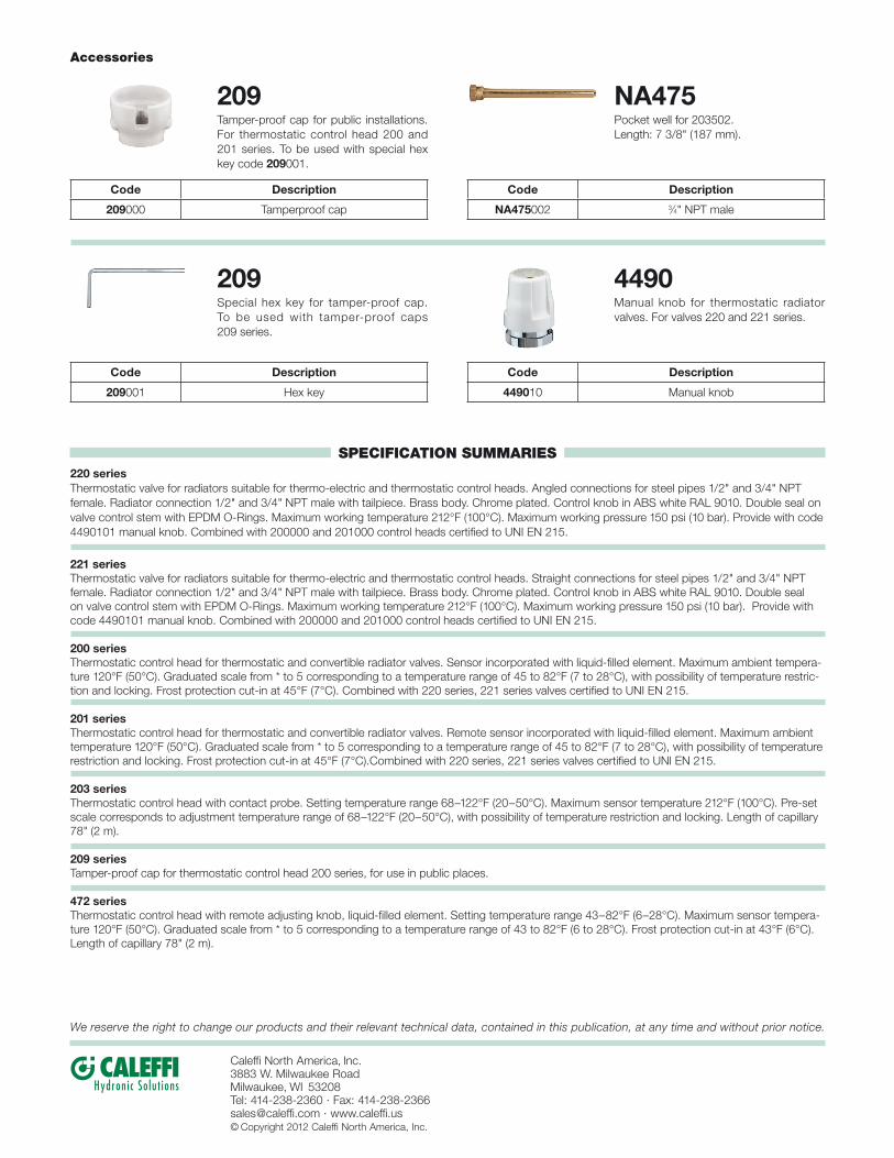
209 seriesTamper-proof cap for thermostatic control head 200 series, for use in public places.
472 seriesThermostatic control head with remote adjusting knob, liquid-filled element. Setting temperature range 43–82°F (6–28°C). Maximum sensor tempera-ture 120°F (50°C). Graduated scale from * to 5 corresponding to a temperature range of 43 to 82°F (6 to 28°C). Frost protection cut-in at 43°F (6°C). Length of capillary 78" (2 m).
SPECIFICATION SUMMARIES
Code Description
209000 Tamperproof cap
Code Description
NA475002 3⁄4" NPT male
Code Description
209001 Hex key
Code Description
449010 Manual knob
209Tamper-proof cap for public installations. For thermostatic control head 200 and 201 series. To be used with special hex key code 209001.
NA475Pocket well for 203502. Length: 7 3/8" (187 mm).
209Special hex key for tamper-proof cap. To be used with tamper-proof caps 209 series.
4490Manual knob for thermostatic radiator valves. For valves 220 and 221 series.
Accessories


![Manual Valves - dpk3n3gg92jwt.cloudfront.net€¦ · Type 546 Ball Valve Standard PVDF With mounting inserts With threaded sockets NPT A NPT [inch] FPM code 3∕ clip-on ring 8 175](https://static.fdocuments.net/doc/165x107/60606b1fc138bb044808e136/manual-valves-type-546-ball-valve-standard-pvdf-with-mounting-inserts-with-threaded.jpg)


