
Supporting Information A Nanogel Based Oral Gene Delivery ... ·

Thermoresponsive Hydrogels for
Mimicking Three-dimensional Microenvironment of
Mesenchymal Stem Cells in Cartilage Tissue Engineering
Amir Mellati
This thesis is submitted for the degree of Doctor of Philosophy
in
School of Chemical Engineering
Faculty of Engineering, Computer and Mathematical Sciences
at
The University of Adelaide
January 2015


i
To my Lovely wife
Hosna
and my sweet daughter
Rasta

ii
iii
PANEL OF SUPERVISORS
Principal Supervisor
Dr. Hu Zhang (PhD)
School of Chemical Engineering
The University of Adelaide
Email: [email protected]
Phone: + 61 8 831 33810
Co-supervisor
A/Prof. Bo Jin (PhD)
School of Chemical Engineering
The University of Adelaide
Email: [email protected]
Phone: +61 8 831 37056

iv
v
Declaration for a thesis that contains publications
I certify that this work contains no material which has been accepted for the award of any
other degree or diploma in my name, in any university or other tertiary institution and, to the
best of my knowledge and belief, contains no material previously published or written by
another person, except where due reference has been made in the text. In addition, I certify
that no part of this work will, in the future, be used in a submission in my name, for any other
degree or diploma in any university or other tertiary institution without the prior approval of
the University of Adelaide and where applicable, any partner institution responsible for the
joint-award of this degree.
I give consent to this copy of my thesis when deposited in the University Library, being made
available for loan and photocopying, subject to the provisions of the Copyright Act 1968.
The author acknowledges that copyright of published works contained within this thesis
resides with the copyright holder(s) of those works.
I also give permission for the digital version of my thesis to be made available on the web, via
the University’s digital research repository, the Library Search and also through web search
engines, unless permission has been granted by the University to restrict access for a period of
time.
Name: Amir Mellati
Signature:…………………………………… Date:……………………

vi
vii
Preface
This doctoral thesis is prepared in “Publication” format according to the “Specifications for
Thesis (2015)” of the University of Adelaide. It includes publications that have been
published, submitted for publication, or prepared in publication format:
1- A. Mellati and H. Zhang. Expansion of stem cells by nanotissue engineering, in Stem-
cell nanoengineering (eds H. Baharvand and N. Aghdami), 2015, John Wiley & Sons
Inc., Hoboken, NJ. DOI: 10.1002/9781118540640.ch14
2- A. Mellati, S. Dai, J. Bi, B. Jin, and H. Zhang. A biodegradable thermoresponsive
hydrogel with tunable properties for mimicking three-dimensional microenvironments
of stem cells. RSC Advances, 2014, 4(109): 63951-63961.
DOI: 10.1039/C4RA12215A
3- A. Mellati, M. Valizadeh, S. Dai, J. Bi, B. Jin, and H. Zhang. Influence of polymer
molecular weight on the cytotoxicity of poly (N-isopropylacrylamide). Colloid and
Interface Science Communications. (Submitted and under review, Reference number:
COLCOM-D-14-00131)
4- A. Mellati, C.M. Fan, A. Tamayol, S. Dai, J. Bi, B. Jin, C. Xian, A. Khademhosseini
and H. Zhang. Microengineered 3D cell-laden thermoresponsive hydrogels as a
platform for bi-zonal cartilage tissue engineering using mesenchymal stem cells.
(Prepared in publication style)
5- A. Mellati, M. Valizadeh, S. H. Madani, S. Dai, J. Bi, B. Jin and H. Zhang. Poly (N-
isopropylacrylamide)/chitosan hybrid as a three-dimensional microenvironment for
stem cells in cartilage tissue engineering. (Prepared in publication style)

viii
ix
Some relevant components of the work have been presented in conferences:
1- H. Zhang, A. Mellati, S. Dai. A thermoresponsive hydrogel-based stem cell culture
platform, Tissue Engineering & Regenerative Medicine International Society Asia-
Pacific Annual Conference 2014 (TERMIS-AP 2014), 24-27 Sep 2014, Daegu, South
Korea (Oral presentation)
2- A. Mellati, S. Dai, B. Jin, H. Zhang. Chitosan-g-PNIPAAm: A thermoresponsive
hydrogel as a 3D microenvironment for MSCs. 2013 Royal Australian Chemical
Institute SA Student Polymer & Bionanotechnology Symposium (SASPBS'13), 4 Oct
2013, Adelaide (Poster presentation)
During the PhD candidature, some relevant researches were conducted in collaboration with
other researchers which led to a publication or conference presentation. The finalized works
are:
1- S. Zheyu, A. Mellati, J. Bi, H. Zhang and S. Dai. A thermally responsive cationic
nanogel-based platform for three-dimensional cell culture and recovery. 2014, RSC
Advances 4(55): 29146-29156. DOI: 10.1039/C4RA02852J
2- A.W. Thomson, A. Mellati and H. Zhang. Chitosan-nanoparticle hydrogel complexes
for bone tissue engineering. BioProcessing Network 2011 (BPN 2011), October 18-20,
2011, Adelaide (Poster presentation)
In addition, some awards were achieved during the PhD work:
1- Research Abroad Scholarship, The University of Adelaide, 2014 (The scholarship was
awarded upon receiving an offer of pre-doctoral research fellow from Prof.
Khademhosseini Lab, Harvard-MIT Division of Health Science and Technology,
Cambridge, USA, May-June 2014)

x

xi
2- Young Investigator Award 2011, BioProcessing Network, 2011
3- Adelaide Scholarship International, the University of Adelaide, 2011

xii

xiii
Acknowledgement
I would like to acknowledge all the people who had a significant role in my achievements as
without their help I would not have been able to get to this point.
I gratefully acknowledge my supervisor Dr. Hu Zhang for his tremendous effort and support
during my candidature. His valuable scientific support, encouragement and constructive
criticisms led me to the goal. In stressful moments of research his availability, patience and
guidance were vital for my success. I also would like to thank my co-supervisor A/Prof. Bo Jin
for not only giving research supports but also polishing my publications. I am particularly
grateful to A/Prof. Sheng Dai for his guidance, suggestions and support. What I learnt from
him is beyond the science. I would like to thank A/Prof. Jingxiu Bi for her great advices and
support. The knowledge that I have gained from my supervisors and academic members of
research group is not only valuable for my PhD, but also benefit my whole career and life. I
also thank A/Prof. Zheyu Shen for his support during his stay in the lab.
I would like to acknowledge heads of school during these years, Prof. Mark Biggs and Prof.
Peter Ashman for their willingness to support.
Many thanks go to Prof. Cory Xian for letting me work in his lab and learning from his great
team in Sansom Institute for Health Research. I also thank Dr. Chi-ming Fan and Dr. Rosa
Chung to help me in performing experiments there.
I would like to acknowledge Prof. Ali Khademhosseini for giving me the chance to work in
his lab at Harvard-MIT Division of Health Sciences and Technology (USA). It helped me to
develop my technical skills and broaden my perspective. I also thank Dr. Ali Tamayol who
provides me with his support to conduct my experiments there.
Many thanks go to all my lab members, staff of the School of Chemical Engineering, Adelaide
Microscopy and the University of Adelaide for their scientific, technical and administrative
help and support.
I would like to specially thank the University of Adelaide for providing me a full scholarship
to study and live in Australia.
Special thanks go to all my wonderful friends in the School of Chemical Engineering, in
particular Meisam Valizadeh and Hadi Madani for their support and scientific collaboration.

xiv

xv
The place I stand today would not be possible without my wife’s patience and devotement.
Thank you Hosna, for accompanying and supporting me on my PhD journey, and my little
daughter, Rasta, thank you for giving unsparing love to your busy dad.
Finally, I would also like to thank my parents for their endless love and encouragement
throughout my life and studies.

xvi

xvii
Abstract
Articular cartilage covers the bone heads of articulating joints to decrease the friction between
bones. Unfortunately, articular cartilage has limited self-repair potential. Cartilage tissue
engineering is a promising therapeutic approach, and its success strongly depends on our
understanding and ability to mimic the complex three-dimensional microenvironment for cells
and their surrounding native extracellular matrix (ECM) in articular cartilage. In particular,
recreating the zonal organisation of articular cartilages makes the process more challenging.
My PhD thesis aims to design and develop chitosan-based thermoresponsive matrices with
tailored physical, mechanical and chemical properties to fulfill microenvironmental
requirements of mesenchymal stem cells (MSCs) in order to promote functional articular
cartilage regeneration. The matrices are then micro-manipulated for resembling the spatially
varying architecture of articular cartilage zones.
To achieve these aims, chitosan-g-poly (N-isopropylacrylamide) (CS-g-PNIPAAm) hydrogel
with a random chain length of grafts was synthesized through free radical polymerization. The
influence of various polymerization conditions on physical and mechanical properties was
systematically investigated. Its suitability for mimicking microenvironment for MSC culture
was studied using cell viability assays. The best CS-g-PNIPAAm in terms of its cell
compatibility and cell culture performance was used in fabrication of microengineered
constructs for regenerating the superficial zone and the middle zone of articular cartilage.
Chondrogenic differentiation of embedded MSCs was evaluated through ECM components
(glycosaminoglycan (GAG), total collagen and collagen type II) analysis. Cellular
organisation and morphology within microchannels were determined using cell alignment and
elongation quantification methods. To further control the chain length of PNIPAAm, well-
defined and narrow-dispersed molecular weights of PNIPAAm were synthesized through atom
transfer radical polymerization (ATRP). Influence of the polymer molecular weight on
cytotoxicity and the cell death mechanisms were investigated through standard assays. Finally,
chitosan/well-defined PNIPAAm (CSNI) hybrids were prepared using low/no toxic
PNIPAAms. MSCs mixed with PNIPAAm solution and were seeded in the voids of the
chitosan scaffolds. The phase separation of PNIPAAm at 37 oC led to a hybrid matrix for
MSCs. The structural characteristics of the hybrids were studied and chondrogenic

xviii
differentiation of incorporated MSCs was evaluated through measuring GAG and total
collagen deposition.
Various copolymerization conditions of CS-g-PNIPAAm have been optimised to obtain the
best hydrogel for MSC culture with desired physical and mechanical properties. After MSC
proliferation, MSCs can be recovered by separating cells from the polymer solution at room
temperature using the sol-gel thermo-reversible property of the CS-g-PNIPAAm copolymer. It
has been demonstrated that the CS-g-PNIPAAm copolymer hydrogel can provide an
appropriate microenvironment for 3D cultivation of MSCs.
Biochemical analysis demonstrates that the CS-g-PNIPAAm hydrogel can support the
embedded MSCs differentiation into chondrocytes in 3D. Histological and
immunohistochemical stainings also confirm the increasing accumulation of GAG and
collagen type II. The CS-g-PNIPAAm hydrogel with manipulated properties can be
micropatterned for regenerating the superficial zone and the middle zone of articular cartilage.
The cell-laden hydrogel micropatterned in 50-100 µm constructs can organize cells along the
microchannel horizontal axis. The cell shape and alignment in the constructs is very similar to
the superficial zone of chondrocytes of the native cartilage. Meanwhile, cells in the
microchannel with the gap above 150 µm are randomly distributed which can be used to
mimic the middle zone of the cartilage tissue.
The cytotoxicity of PNIPAAm is molecular weight dependent, and varies with the PNIPAAm
chain length. Low molecular weight PNIPAAm (degree of polymerization (DP) = 35) is
inherently toxic to cells, and necrosis is the dominant cell death mechanism. Moderate-sized
PNIPAAms with their DP between 100 and 200 are non-cytotoxic. For the PNIPAAm with a
higher molecular weight (DP = 400, P-400), cell viability is dependent on the assay method.
The P-400 hydrogel is detrimental to stem cells when the cells are covered with a thick layer
of gel, and this layer may become a barrier for nutrient or oxygen delivery to cells.
The CSNI hybrid matrices composed of chitosan scaffolds and well-defined PNIPAAm with a
degree of polymerization of 400 (CSNI400) can provide a supporting platform for 3D stem
cell culture and cartilage tissue engineering. Matrix characterization shows improved
structural properties of CSNI400 in comparison with CSNI100 and the chitosan-alone
scaffold.

xix
In conclusion, we are able to create and refine 3D microenvironment for stem cells through
manipulation of matrices in order to enhance cell proliferation and chondrogenic
differentiation. Our results reveal that graft copolymer of chitosan and PNIPAAm with
tailored properties and microengineered architecture is appealing for zonal cartilage tissue
engineering. The hybrid matrices from chitosan scaffolds with well-defined PNIPAAm
hydrogels promote chondrogenesis, better than the graft copolymer.
Graft copolymerization of chitosan and well-defined PNIPAAms (CS-g-W-PNIPAAm),
microengineering of CSNI hybrids, and CS-g-W-PNIPAAm, stacking the microengineered
constructs to form a macroscale 3D cartilage tissue, and in vivo implantation of engineered
tissues should be addressed in future projects.

xx

xxi
Table of Contents Introduction .......................................................................................................................... 1 1.
1.1 Background: cartilage failures and tissue engineering ...................................................... 3
1.2 Aims and objectives .......................................................................................................... 4
1.3 Thesis structure .................................................................................................................. 5
1.4 References ......................................................................................................................... 8
Literature Review ................................................................................................................ 9 2.
2.1 Biology, structure and functions of native cartilage ........................................................ 11
2.2 General features of biomaterials as cell matrices ............................................................ 13
2.3 Structural features of matrices ......................................................................................... 14
2.4 Nanostructured platforms as matrices for 3D stem cell culture ...................................... 16
2.5 Matrices for cartilage tissue engineering ......................................................................... 34
2.5.1 Hydrogels .................................................................................................................. 35
2.5.2 Thermoresponsive hydrogels .................................................................................... 37
2.5.3 Chitosan-based thermoresponsive hydrogels............................................................ 37
2.6 Cells for cartilage tissue engineering .............................................................................. 40
2.7 Conclusions ..................................................................................................................... 40
2.8 References ....................................................................................................................... 42
A Biodegradable Thermoresponsive Hydrogel with Tunable Properties for Mimicking 3.
Three-Dimensional Microenvironments of Stem Cells ............................................................ 57
3.1 Abstract ........................................................................................................................... 60
3.2 Introduction ..................................................................................................................... 60
3.3 Materials and methods ..................................................................................................... 63
3.3.1 Materials ................................................................................................................... 63
3.3.2 Synthesis of chitosan-g-PNIPAAm .......................................................................... 63
3.3.3 Conductometric and potentiometric titration ............................................................ 64
3.3.4 FTIR spectroscopy .................................................................................................... 64
3.3.5 Rheological characterization..................................................................................... 65
3.3.6 Solubility ................................................................................................................... 65
3.3.7 Hydrogel morphology ............................................................................................... 65

xxii
3.3.8 Cell culture ................................................................................................................ 65
3.3.9 3D cell culture ........................................................................................................... 66
3.3.10 MTT assay ............................................................................................................... 66
3.3.11 Confocal Laser Scanning Microscopy .................................................................... 66
3.4 Results and discussion ..................................................................................................... 67
3.4.1 Synthesis and characterization of chitosan-g-PNIPAAm ......................................... 67
3.4.2 Solubility ................................................................................................................... 76
3.4.3 Rheological measurements ........................................................................................ 78
3.4.4 Morphological studies ............................................................................................... 81
3.4.5 In vitro three-dimensional cell culture ...................................................................... 82
3.5 Conclusions ...................................................................................................................... 86
3.6 References ........................................................................................................................ 87
Microengineered 3D Cell-laden Thermoresponsive Hydrogels as a Platform for Bi-zonal 4.
Cartilage Tissue Engineering Using Mesenchymal Stem Cells ................................................ 93
4.1 Abstract ............................................................................................................................ 96
4.2 Introduction ...................................................................................................................... 97
4.3 Materials and methods ................................................................................................... 100
4.3.1 CS-g-PNIPAAm synthesis and characterization ..................................................... 100
4.3.2 3D cell culture in hydrogel ...................................................................................... 100
4.3.3 The MTT assay ........................................................................................................ 101
4.3.4 3D MSC differentiation in hydrogel ....................................................................... 102
4.3.5 Biochemical analysis ............................................................................................... 102
4.3.6 Histological and immunohistochemical staining .................................................... 103
4.3.7 Micropatterning of CS-g-PNIPAAm ....................................................................... 104
4.3.8 Live/dead cell staining ............................................................................................. 105
4.3.9 Quantification of cellular alignment and elongation ............................................... 105
4.3.10 Multiphoton microscopy ....................................................................................... 106
4.3.11 Statistical analysis ................................................................................................. 106
4.4 Results and discussion ................................................................................................... 107
4.4.1 Hydrogel optimization for 3D cell culture .............................................................. 107
4.4.2 3D MSC differentiation in hydrogel ....................................................................... 109

xxiii
4.4.3 3D cell-laden microconstructs: Preparation, cell organization and chondrogenesis
......................................................................................................................................... 113
4.5 Conclusions ................................................................................................................... 123
4.6 References ..................................................................................................................... 124
Influence of Polymer Molecular Weight on the Cytotoxicity of Poly (N-5.
isopropylacrylamide)............................................................................................................... 133
5.1 Abstract ......................................................................................................................... 136
5.2 Introduction ................................................................................................................... 137
5.3 Materials and methods ................................................................................................... 137
5.3.1 Materials ................................................................................................................. 137
5.3.2 ATRP of PNIPAAm ............................................................................................... 138
5.3.3 Dynamic light scattering (DLS) .............................................................................. 138
5.3.4 Cell culture .............................................................................................................. 139
5.3.5 MTT assay .............................................................................................................. 139
5.3.6 Phase contrast and atomic force microscopy of polymer precipitates .................... 140
5.3.7 Flow cytometry ....................................................................................................... 140
5.4 Results and Discussion .................................................................................................. 141
............................................................................................................................................. 153
5.5 Acknowledgement ......................................................................................................... 154
5.6 References ..................................................................................................................... 155
Poly (N-isopropylacrylamide)/Chitosan Hybrid as a Three-dimensional 6.
Microenvironment for Stem Cells in Cartilage Tissue Engineering ....................................... 159
6.1 Abstract ......................................................................................................................... 162
6.2 Introduction ................................................................................................................... 163
6.3 Materials and methods ................................................................................................... 164
6.3.1 Materials ................................................................................................................. 164
6.3.2 Preparation of scaffolds .......................................................................................... 164
6.3.3 Dynamic light scattering ......................................................................................... 165
6.3.4 Thermal analysis ..................................................................................................... 165
6.3.5 Gas absorption ........................................................................................................ 166
6.3.6 Swelling ratio .......................................................................................................... 166

xxiv
6.3.7 Preparation of cell-laden scaffolds .......................................................................... 167
6.3.8 Scanning electron microscopy ................................................................................. 167
6.3.9 Mitochondrial activity measurement ....................................................................... 168
6.3.10 Confocal laser scanning microscopy ..................................................................... 168
6.3.11 Chondrogenic induction ........................................................................................ 169
6.3.12 Biochemical assays ................................................................................................ 169
6.3.13 Statistical analysis ................................................................................................. 170
6.4 Results and discussion ................................................................................................... 170
6.4.1 Scaffold preparation and characterization ............................................................... 170
6.4.2 Cell proliferation ..................................................................................................... 180
6.4.3 Chondrogenic differentiation .................................................................................. 183
6.5 Conclusions .................................................................................................................... 185
6.6 Acknowledgements ........................................................................................................ 186
6.7 References ...................................................................................................................... 187
Conclusions and future directions .................................................................................... 193 7.
APPENDIX: Published papers in their Journal styles ............................................................. 199

1
CHAPTER ONE
Introduction 1.

2

3
1.1 Background: cartilage failures and tissue engineering
Cartilage-related diseases are one of the most reasons for disabilities around the world.
Osteoarthritis is already one of the ten most disabling diseases in developed countries. 55.3
million people are affected by arthritis diseases worldwide (1). 9.6% of men and 18.0% of
women aged over 60 years have symptomatic osteoarthritis (2). In Australia, osteoarthritis
is a major cause of disability, psychological distress and poor quality of life (3). In 2007-
08, 15% of people reported that they currently had arthritis (4). 62.5% of people with
profound/severe disability and 32% of people without disability reported to have arthritis
in the 75 and over age group (5). It was 4% of the disease burden in Australia in 2007-08
and cost 7.5% ($4.0 billion) of total allocated health expenditure in 2004-05 (6). 4.6% of
deaths registered in 2009 were due to arthritis and musculoskeletal diseases (underlying or
associated) (7). Other countries also suffer from the same problem. These diseases cost
$128 billion for US economy per annum (5). In Canada, a 2006 study found that for adults
aged 15 years and over with disabilities, the most common issue was arthritis (1). On the
other hand, cartilage can be damaged from accidents such as car crashes or work and sport
injuries. Articular cartilage injuries of the knee are reported as the most common reason of
permanent disabilities in athletes (8). According to the “Australian Safety and
Compensation Council” report, over 76,000 compensation claims for acute and chronic
musculoskeletal disorders in 2003 were made, representing 43% of all injuries and disease-
related claims (9). Unfortunately, articular cartilage has limited repair potential (10). Poor
self-repair capacity of cartilages becomes the major challenge for the therapeutic strategy
especially in young and active individuals, because they need to return to sport and
working activities quickly.
There are different approaches to repair a damaged articular cartilage. These therapeutic
strategies can be divided into two major categories (11). The first category is “without
biologic therapies”, such as lavage and arthroscopy, chondral shaving, laser abrasion/ laser
chondroplasty, abrasion chondroplasty, pridie drilling and microfracture, spongialization,
debridement and extensive surgical interventions e.g. osteotomy and distraction of joints.
The second category consists of “with active biologic therapies”, such as autologous tissue

4
transplantation, osteochondral transplantation (mosaicplasty), allogenic osteochondral,
chondral grafting, and tissue engineering.
Tissue engineering is one of the most promising therapies for patients with organ failure
and damaged or diseased tissues. The appropriate cells are incorporated within a three-
dimensional (3D) matrix and grown under a suitable condition to form the new functional
tissue. There are two major elements to be considered in tissue engineering: cells and cell
microenvironment. Matrices are the main component of the cellular microenvironment.
They serve as artificial temporary scaffolds for cells. These scaffolds are often made by
mimicking the native extracellular matrix (ECM). The cell-ECM interactions are essential
requirements for cell and tissue functionality. Other signaling factors such as bioactive
molecules and mechanical or electrical stimulations may also be considered in designing a
microenvironment. Controlling the variables of microenvironment in order to provide
mimicking physiological conditions in a 3D manner forms the key component of tissue
engineering.
1.2 Aims and objectives
Many research groups and scientists have been working on regenerating functional
cartilage tissues and implanting them into the patient body. Despite of many promising
trials, there are still no off-the-shelf products in the market which can fully address all the
clinical needs for treatment and many challenges remain to be resolved. Successful
cartilage tissue engineering requires more efforts to control microenvironmental cues.
Novel biomaterials with precisely engineered properties should be prepared to provide a
suitable 3D microenvironment to regulate cell fate and cellular activities, including
adequate proliferation to obtain sufficient homogenous cells, and differentiation toward the
desired cell line and deposition of extracellular matrix with chondrogenic phenotype.
Hence, in this PhD project, I aim to design and develop a serial of chitosan-based
thermoresponsive matrices with controlled properties to fulfill microenvironmental
requirements of mesenchymal stem cells (MSCs) in order to promote functional articular
cartilage regeneration.
5
Specific objectives of my PhD project are:
To synthesize and characterize a range of chitosan-based thermoresponsive
matrices with different mechanical properties for cartilage tissue engineering;
To correlate the synthesized polymer chemical structure and its physical,
mechanical and biological properties with cellular responses, and to exploit
matrices with tailored properties for recreating the most appropriate 3D
microenvironment for cells;
To replicate the zonal structure of native cartilages using micro-engineered cell-
laden thermoresponsive hydrogels;
To evaluate the biological characteristics of engineered cartilages through standard
assays.
1.3 Thesis structure
The thesis is written in a paper-based format. I start my thesis with the Introduction chapter
to highlight the importance of my PhD work, and critically review the recent contributions
to cartilage tissue engineering to identify research gaps in the second chapter. Major
experimental results are written in Chapter 3 to 6. The thesis finishes with the conclusion
and future directions derived from my experiments.
In the first chapter of this thesis, the background, research gaps, aims and objectives, and
the thesis outline are introduced.
In the second chapter, the biological background of native articular cartilage structure and
functions is described. Cells and their microenvironments are further discussed in cartilage
tissue engineering. Biomaterials, particularly nanostructured biomaterials, developed for
3D stem cell culture and expansion are reviewed. The effect of nanoscale features of
microenvironment on stem cell infiltration, adhesion, migration and proliferation is
discussed.
In chapter three, based on the literature review, chitosan was selected as the base material
for cartilage tissue engineering. Poly (N-isopropylacrylamide) was grafted onto chitosan to

6
make it thermo-responsive. These thermo-responsive hydrogels can be injected into
cartilage defect sites in a minimally invasive manner. Therefore, chitosan-g-poly(N-
isopropylacrylamide) (CS-g-PNIPAAm) copolymers were synthesized. The influence of
various polymerization conditions, such as acid concentration, reaction temperature and
monomer feed, on the grafting parameters of this thermo-responsive hydrogel, was
systematically investigated. In a physiological pH, optimized balance between the
solubility (as the pre-requirement for cell dispersion and injectability) of copolymers at
ambient temperature and enhanced gel mechanical strength (as the essential parameter of
stem cell microenvironments) at body temperature was achieved through controlled
reaction conditions. The viability and proliferation of mesenchymal stem cells (MSCs) in
this hydrogel was investigated.
In the fourth chapter, MSCs were incorporated within CS-g-PNIPAAm hydrogel and their
chondrogenic differentiation was studied quantitatively by biochemical assays and
qualitatively by histological and immunohistochemical assessments. Micropatterning was
employed to mimic cellular shape and orientation within the superficial and middle zones
of the natural cartilage. Thermo-responsiveness of CS-g-PNIPAAm was exploited to cast
the cell-laden gels within micromolds. Cell alignment and elongation within three-
dimensional micropatterned cell-laden hydrogels were evaluated.
In the fifth chapter, a serial of PNIPAAms with well-defined molecular weights were
synthesized through atom transfer radical polymerisation (ATRP) and polymer molecular
weight-dependent cytotoxicity was examined in order to obtain the less toxic PNIPAAm
chain length for thermoresponsive scaffold design in the next chapter.
In the sixth chapter, another form of chitosan and PNIPAAm was investigated. Non-toxic
or low-toxic PNIPAAms were chosen based on the results of Chapter 5 for fabrication of a
hybrid chitosan and PNIPAAm scaffold. The scaffold was characterized using thermal
analysis, dynamic light scattering and swelling ratio measurement. The morphological
structure of the scaffold was investigated in micro- and nano-scale. Influence of PNIPAAm
molecular weight on cell viability and self-renewal in a 3D microenvironment was studied
and the suitability of the hybrid scaffold for cartilage tissue engineering was evaluated
using biochemical assays.

7
Chapter Seven comprises the conclusions and future directions derived from current
findings in this PhD project.
8
1.4 References
1. Selected long-tem health conditions, aspects of disability and health in Australia (
2007-2008): Australian Bureau of Statistics2011.
2. Chronic rheumatic conditions: World Health Organization, Department of Chronic
Diseases and Health Promotion, Respiratory Diseases and Arthristis2011.
3. A picture of osteoarthritis in Australia: Department of Health and Ageing,
Australian Institute of Health and Welfare2007.
4. Year book Australia, 2009–10, chronic disease: Australian Bureau of
Statistics2010.
5. Spiller KL, Maher SA, Lowman AM. Hydrogels for the Repair of Articular
Cartilage Defects. Tissue Engineering Part B: Reviews. 2011;17(4):281-99.
6. Arthritis and osteoporosis in Australia - a snapshot ( 2007-08) Australian Bureau of
Statistics2011.
7. Causes of death 2009: Australian Bureau of Statistics2011.
8. McAdams TR, Mithoefer K, Scopp JM, Mandelbaum BR. Articular cartilage injury
in athletes. Cartilage. 2010;1(3):165-79.
9. Worked related musculoskeletal disease in Australia: Australian Saftey and
Compensation Council2006.
10. Haleem AM, Chu CR. Advances in tissue engineering techniques for articular
cartilage repair. Operative Techniques in Orthopaedics. 2010;20(2):76-89.
11. Hunziker EB. Articular cartilage repair: basic science and clinical progress. A
review of the current status and prospects. Osteoarthritis and Cartilage. 2002;10(6):432-63.

9
CHAPTER TWO
Literature Review 2.

10
11
2.1 Biology, structure and functions of native cartilage
Cartilage is a connective tissue in human or animal bodies. Three different types of
cartilages are distinguishable: hyaline cartilages (e.g. articular cartilages), elastic cartilages
in epiglottis and eustachian tube, and fibrocartilages in intervertebral discs,
temporomandibular joint and meniscus (1). Articular cartilage is a thin layer of hyaline
cartilage covering the bone heads of articulating joints to decrease the friction between
bones of a joint. These soft tissues have outstanding properties such as shock absorption,
wear resistance and high lubrication (2). There are no blood vessels and nerves within
articular cartilages. Articular cartilage is a multiphasic tissue consisting of chondrocyte
cells (less than 10% of the total volume), interstitial fluid (approximately 80% by wet
weight), which is mostly water, and solid phase or extracellular matrix (ECM)
(approximately 20% by wet weight). ECM contains collagen fibers (approx. 60% of dry
weight), proteoglycans (PGs) (10-15% of wet weight) and other protein and glycoprotein
macromolecules (Fig.2-1). 90-95% of the collagen content is collagen type II and a minor
amount of types V, VI, IX, X and XI are also present in articular cartilages (2). Collagens
provide tensile stiffness of cartilage and proteoglycans are responsible for its compressive
strength.
Four zones or layers are identified in articular cartilages (2, 3) as shown in Fig.2-2. The
superficial or tangential zone is the closest layer to the cartilage surface. This layer
represents 10-20% of the total thickness. This zone is rich in water and PGs are at the
minimum level. Chondrocytes are ellipsoidal and parallel to the surface. Collagen fibrils
lie also parallel to the surface. The middle or transitional zone is laid under the superficial
zone. Its thickness is 40-60% of the total thickness. Chondrocytes are rounder and collagen
fibrils are larger in diameter in comparison to the superficial zone. Both chondrocytes and
collagen fibrils are randomly aligned. The PG content is at its highest level. The deep zone
is below the middle layer and contains the minimum water amount. Chondrocytes are
spherical in shape and are aligned columnar and perpendicular to the tidemark which is a
boundary line between the deep zone and the lowest layer (i.e. calcified zone) of the
cartilage. Collagens are perpendicular to the tidemark too. The calcified zone anchors the

12
Figure 2-2. Zonal organisation of articular cartilage. (a) Chondrocyte shape and
alignment, (b) collagen alignment. (Reproduced with permission from (3))
Figure 2-1. Structure of articular cartilage extracellular matrix.
(Reprinted with permission from (3))

13
hyaline cartilage to the subchondral bone. Chondrocytes are small and randomly
distributed in a matrix of apatitic salts.
Due to its avascular nature, articular cartilage has limited capacity for self-repair. Articular
cartilage also contains a sophisticated zonal structure. To restore the normal functions of
the cartilage, a myriad of issues have to be addressed for regenerating functional cartilage,
especially on optimizing the microenvironment for stem cell culture and differentiation.
The objective of this study was to regenerate articular cartilage by synthesizing
biomaterials with tailored properties for 3D stem cell expansion and differentiation as well
as cartilage formation. Therefore, we will discuss important features of biomaterials as cell
matrices. Then we will review the literature on biomaterials and their nano-level aspects
for 3D cell culture and expansion, followed by a specific focus on biomaterials for
mimicking matrices for tissue engineering, especially cartilage tissue engineering.
2.2 General features of biomaterials as cell matrices
The matrices should be biocompatible. Matrices and their degradation by-products should
be safe to the host tissue with no inflammatory responses and they should be nontoxic to
seeded cells. The matrices should be able to provide supports for cells to adhere and
function. They need to provide the primary mechanical strength of the defect site during
the tissue regeneration in vivo (4). Sufficient mechanical strength in highly stressed joints
to match those of native tissue is another necessity (5, 6). They may also mediate
mechanical signals to cells for stimulating cell proliferation and differentiation (7). Porous
matrices are often required for regenerating cartilage tissues. Cartilage tissues are
avascular. Hence, the matrix should have a suitable architecture to deliver nutrients and
exhaust cell wastes. Porous structure provides essential pathways to deliver nutrients to the
cells which are attached within scaffold pores. Moreover, pores allow cells to attach,
spread, proliferate, migrate and produce extracellular matrix. Furthermore,
biodegradability of the matrices is an important parameter. They need to be eliminated as a
result of biological reactions in a timely manner that matches cell modeling/remodeling,

14
ECM production and neo-tissue formation (4). The matrices may also provide physical,
mechanical, or biological cues for cells. The matrix-cell dynamic interactions can regulate
cell behaviours and fate (157). Bioactive molecules may be encapsulated in the matrices
and then released from them in a temporal and spatial way to induce cells to grow and
differentiate into specific tissue with desired functionality (8).
2.3 Structural features of matrices
Tissue engineers have recognized that structural aspects can have profound influences on
cell behaviours (9). Recent studies show that cell adhesion, migration, proliferation,
differentiation, morphogenesis and apoptosis, not only depend on macrostructure of the
microenvironment, but also rely on nano- and micro-scale features of the ECM in the
microenvironment (10). Therefore, the success in tissue engineering strongly depends on
our understanding and ability to mimic the complex 3D architecture of the native ECM in a
multiple length scale (11).
Macro-scale structure is important to make the desired shape and size of the defect site,
and to offer enough mechanical strength for tissue formation. Micro-scale level of scaffold
design is usually related to tissue architectures. For example, oriented parallel fibres are
beneficial for reconstructing peripheral nerve (12), while random non-woven fibres may be
more important for dermal replacement (13,14). Micro-structural features are also essential
for ensuring cell adhesion and migration and determining the overall mechanical properties
(15). Particular attention has been drawn to pore size, connectivity, and geometry of 3D
matrices (16). Pore size should be relatively large because most of the adherent stem cells
have a size ranging from 10 to 150 μm. A large-pore structure allows delivering a
sufficient number of cells and cell migration, while the inter-connected porosity offers
efficient diffusion of nutrients and metabolic waste removal (17,18).
The multi-scale requirements have motivated the development of new fabrication
processes that can produce biomaterials with specific three-dimensional (3D) micro- and
nanostructures in which pore structure, surface area to volume ratio, texture and surface
topography can be manipulated to control cell-matrix and cell-cell interactions (9).

15
Microfabrication technologies such as emulsification (to produce microgels),
photolithography, micromolding, microfluidics, 3D bioprinting are emerging approaches to
replicate cellular microenvironment in vitro or to fabricate tissue engineering matrices with
microscale resolutions (19-21). Microtechnologies can be employed in various orders to
control individual cell-cell interactions, to control the structure of clusters of cells, or to
control interactions between multiple cell clusters (21). For example, they can be utilized
to generate microvasculature within scaffolds (22). Micromolded poly(glycerol sebacate)
(PGS) (23) capillaries and cell-laden agarose microfluidic channels (24) were fabricated as
vascularized scaffolds. Furthermore, in a bottom up approach, microengineered constructs
can be assembled as building blocks to fabricate larger tissues with controlled biomimetic
microarchitecture (25, 26).
Microfabrication techniques can also be used to control the porosity and microarchitecture
of pores (pore size, pore shape, interconnectivity and etc.) (27). These structural features
play an important role in regulating engineered tissue properties. Various methods have
been utilized to fabricate porous scaffolds, such as solvent casting/particle leaching, freeze-
drying, gas foaming, and electrospinning. Porosity and microarchitectural features of pores
can be tailored by changing the preparation conditions in various methods (27). Scaffold
nanopores are also important jn controlling over tissue architecture and they expand our
ability to direct cell fate and improve tissue growth and function (28). Nanoporous
structure of membranes has been shown to significantly affect cellular response (29).
Nanoporous membranes can also provide an antigen barrier around encapsulated cells to
prevent host immune rejection, while preserve their capabilities for nutrient and oxygen
delivery and metabolic waste removal (30). Nanopores are useful for the crystallization of
hydroxycarbonate apatite (HCA) and cell adhesion in bone tissue engineering (31). Change
in nanoscale textural porosity of macropore walls can alter their mechanical strength which
has a significant effect on cellular activity (32). Besides the nanoporous structures, some
platforms with nano-scaled features such as nano-fibres, nano-composites and surface-
modified nano-structures are being used to control cell behaviors. We will describe these
platforms as matrices for 3D stem cell culture in the following section.

16
2.4 Nanostructured platforms as matrices for 3D stem cell
culture1
Nano-scale elements of native cells and tissues have become more important for
understanding stem cell behaviours. Especially, nano features of ECM have a big impact
on stem cell adhesion, migration, proliferation and controlled differentiation. Fig. 2-3
summarized the nano-level aspects of ECM and benefits of resembling these features using
nano-structured matrices.
ECM consists of structural protein fibres (collagen and elastin), adhesive proteins
(fibronectin and laminin), glycosaminoglycans (GAGs) and proteoglycans (PGs). These
proteins have dimensions between 10 to several hundred nanometers (34).
ECM nano-topology also regulates stem cell behaviours, ranging from changes in cell
adhesion, cell orientation, cell motility, surface antigen display, cytoskeletal condensation,
activation of tyrosine kinases, and modulation of intracellular signaling pathways that
regulate transcriptional activity and gene expression (35). The nano-topology may include
dimensional scale from nanometer to micrometer and types of topological forms such as
ridges, steps, grooves, pillars and pits (35). Structural ECM features, such as fibrils and
pores, are often of a size compatible with cellular processes involved in migration, which
may influence the strategy by which cells migrate through ECM. This size ratio between
cell (1 to 100 µm) and surrounding fibres (1-100 nm) enables the cell to be in direct
contact with the fibres of the ECM thus creating a 3D orientation (34).
1 The section was published as a book chapter in: Stem-Cell Nanoengineering (eds H.
Baharvand and N. Aghdami), John Wiley & Sons, Inc., Hoboken, NJ.
DOI: 10.1002/9781118540640.ch14 (33). It is partially reorganized to be adapted to this
literature review.

17
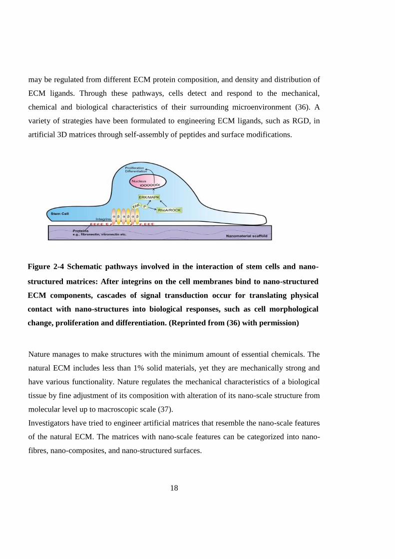
Nano-scale ECM also plays a significant role in signal transduction. Stem cells respond to
the ECM through nano-sized membrane receptors that connect the matrix to the
cytoskeleton. Integrin is one of the main receptors which can recognise Arg-Gly-Asp
(RGD) sequences of ECM proteins. After integrins bind to ECM proteins (such as
fibronectin or vitronectin); the integrin ligation would activate focal adhesion kinase
(FAK) signalling. The activated FAK undergoes auto-phosphorylation and triggers a
downstream signalling of extracellular signal regulated kinase (ERK)/ mitogen activated
protein kinase (MAPK) pathway to transfer mechanical information to the cell nucleus
where the cell DNA reacts to extracellular stimulus by producing changes such as
proliferation and differentiation to cells. Ras homolog gene family, member A (RhoA)/
Rho associated coiled-coil protein kinase (ROCK) pathway can also be triggered by
activated FAK and subsequently activate ERK/MAPK pathway to influence stem cells.
The schematic description of this process is shown in Fig. 2-4. The signaling pathways
Nano-structured matrice
Mimicking ECM components' dimensions
High surface-to-volume ratio
Cell adhesion
Pore size
Cell migration Nutrient delivery
and waste removal
Enhanced proliferation rate
Controlled differentiation
Tissue acceptance after
implantation
Hierarchical organisation at
nano-level
Minimum materials
Mechanical properties
Topographical properties
Figure 2-3 Advantages of nano-structured matrices for regulating stem cell
behaviours
18
may be regulated from different ECM protein composition, and density and distribution of
ECM ligands. Through these pathways, cells detect and respond to the mechanical,
chemical and biological characteristics of their surrounding microenvironment (36). A
variety of strategies have been formulated to engineering ECM ligands, such as RGD, in
artificial 3D matrices through self-assembly of peptides and surface modifications.
Nature manages to make structures with the minimum amount of essential chemicals. The
natural ECM includes less than 1% solid materials, yet they are mechanically strong and
have various functionality. Nature regulates the mechanical characteristics of a biological
tissue by fine adjustment of its composition with alteration of its nano-scale structure from
molecular level up to macroscopic scale (37).
Investigators have tried to engineer artificial matrices that resemble the nano-scale features
of the natural ECM. The matrices with nano-scale features can be categorized into nano-
fibres, nano-composites, and nano-structured surfaces.
Figure 2-4 Schematic pathways involved in the interaction of stem cells and nano-
structured matrices: After integrins on the cell membranes bind to nano-structured
ECM components, cascades of signal transduction occur for translating physical
contact with nano-structures into biological responses, such as cell morphological
change, proliferation and differentiation. (Reprinted from (36) with permission)

19
2.4.1.1 Nano-fibres
Nano-fibres, diameters ranging from 1 to 1000 nm, are the most popular nano-structured
biomaterials which have been widely used in tissue engineering due to the similarity
between nano-fibre structures and ECM fibres diameter size scales, and large surface area
which is favorable for cell adhesion and bioactive factor encapsulation.
There are three commonly used methods to produce nano-fibres: electrospinning, self-
assembly and phase separation (38), and the fibre composition, alignment, diameter,
degradation, and mechanical characteristics can be controlled for different types of tissue
regeneration. Fibres have been fabricated for stem cell expansion using self-assembly
peptides and a range of polymers such as Poly (ε-caprolactone) (PCL), Poly (lactic acid)
(PLA), Poly (D, L-lactide-co-glycolide) (PLGA), and other synthetic or natural polymers
and also their blends or copolymers (Table 2-1).
2.4.1.1.1 PCL
PCL is widely chosen as a FDA-approved model polymer due to its low toxicity, low cost
and ease of fabrication. Disadvantages of unmodified PCL are slow degradation rate
(weeks to months), weak mechanical properties, non-reactivity and hydrophobicity.
Intensive attempts have been made at fabricating PCL fibres for tissue engineering based
on mesenchymal stem cells (MSCs) (39,40-42), ESCs (43), somatic stem cells (SSCs) (44)
and neural stem cells (NSCs) (110) .
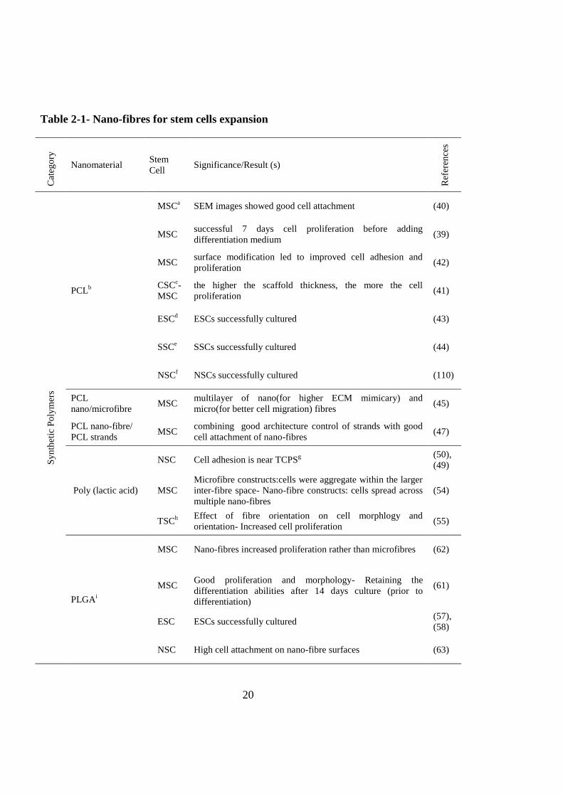
In 2003, Yushimoto et al. explored PCL nano-fibre matrices for expanding MSCs.
Penetration of cells and abundant ECM were observed in the cell-fibre constructs after 1
week. SEM images showed that the surfaces of the constructs were covered with several
layers of cells at fourth weeks (40). Ruckh et al. further quantified cell growth along with
live cell imaging. After a short-term (7 days) culture of MSCs in PCL nano-fibres, live cell
fluorescence staining and MTT assay showed significantly higher proliferation of MSCs
on nano-fibres than 2D control surfaces. SEM analysis also supported the fluorescence
microscopy results that the
20
Table 2-1- Nano-fibres for stem cells expansion
Cat
ego
ry
Nanomaterial Stem
Cell Significance/Result (s)
Ref
eren
ces
Sy
nth
etic
Po
lym
ers
PCLb
MSCa SEM images showed good cell attachment (40)
MSC successful 7 days cell proliferation before adding
differentiation medium (39)
MSC surface modification led to improved cell adhesion and
proliferation (42)
CSCc-
MSC
the higher the scaffold thickness, the more the cell
proliferation (41)
ESCd ESCs successfully cultured (43)
SSCe SSCs successfully cultured (44)
NSCf NSCs successfully cultured (110)
PCL
nano/microfibre MSC
multilayer of nano(for higher ECM mimicary) and
micro(for better cell migration) fibres (45)
PCL nano-fibre/
PCL strands MSC
combining good architecture control of strands with good
cell attachment of nano-fibres (47)
Poly (lactic acid)
NSC Cell adhesion is near TCPSg
(50),
(49)
MSC
Microfibre constructs:cells were aggregate within the larger
inter-fibre space- Nano-fibre constructs: cells spread across
multiple nano-fibres
(54)
TSCh
Effect of fibre orientation on cell morphlogy and
orientation- Increased cell proliferation (55)
PLGAi
MSC Nano-fibres increased proliferation rather than microfibres (62)
MSC
Good proliferation and morphology- Retaining the
differentiation abilities after 14 days culture (prior to
differentiation)
(61)
ESC ESCs successfully cultured (57),
(58)
NSC High cell attachment on nano-fibre surfaces (63)

21
Sy
nth
etic
Po
lym
ers
(Co
nti
nu
ed)
PLGA/Collagen HSCj rapid and rich cell attachment (65)
Polyurethane MSC enhanced attachment and proliferation (66)
polyamide ESC enhanced attachment and proliferation (67)
PESk HSC
Surface-aminated nano-fibres enhance adhesion and
expansion (68)
PES HSC aminated chain length is important factor (69)
Self-assembeled
RAD16 peptide and
its motifs
ESC ESCs successfully cultured (80)
NSC NSCs successfully cultured (82)
hASCl hASCs successfully cultured (81)
Self-assembeled
Multi Domain
Peptide
MSC promoted cell adhesion,migration and expansion (83)
Self-assembeled
Peptide-
amphiphiles
NSC NSCs successfully cultured (84)
MSC MSCs successfully cultured
(85),
(86),
(87)
Nat
ura
l
Po
lym
ers Collagen MSC MSCs successfully cultured (70)
Silk/PEOm
MSC PEO was added to improve processability- Improved
adhesion and proliferation
(71),
(72)
Oth
er M
od
ific
atio
ns
PCLnano-fibre/
PLLA nano-fibre
ESC-
MSC
Cells infiltrated into the scaffold rather than migration along
the surface - enhanced proliferation (78)
P(LLA-CL) n SMC
m enhanced proliferation (73)
starch/PCL MSC
Example of blending with natural materials - combination
of micro and nano-fibres- better morphology and cell
growth
(79)
P(EOT-BT)o MSC
microfibres with nanopores are great for cell adhesion and
proliferation (77)
a: Mesenchymal Stem Cell , b: Poly (ε-caprolactone) , c: Carcinoma Stem Cell , d: Embryonic Stem Cell ,
e: Somatic Stem Cell , f: Neural Stem Cell , g: Tissue Culture Polystyrene , h: Tendon Stem Cell , i: Poly (D,
L-lactide-co-glycolide) , j: Hematopoietic Stem Cell, k: polyethersulfone , l: human Adipose Stem Cell , m:
poly(ethylene oxide) , n: poly (l-lactic-co-ε-caprolactone) , m: Smooth Muscle Cell , o: Poly (ethylene
oxide terephthalate)–poly(butyleneterephthalate)

22
MSCs preferentially adhere, spread and colonize on nano-fibre matrices compared to 2D
surfaces (39). The physical parameters of PCL nano-fibres, such as diameter of the fibres
and morphology of the fibre surface, can influence cell attachment and growth. This has
been confirmed by a study using mouse ESCs (P19) and mouse MSCs. Matrices with a
thickness of 0.6 mm were found to provide a better substrate for cell proliferation rather
than scaffolds with the thickness of 0.1 mm, possibly due to more dimensional stability
(41). To demonstrate that nano-fibre surface modification affects stem cell behaviour, the
surface of the PCL nano-fibres was modified by He+-irradiation which led to slight smooth
surface and different nano-scale surface chemical structures. The results showed that early
attachment, further proliferation as well as osteoblastic markers, were higher for MSC on
He+-irradiated PCL (42).
One of the drawbacks of nano-fibre matrices is their small pore size which results in poor
cell infiltration and migration. To capitalize on the properties of micro-fibres (i.e., pores
large enough for cell migration) and nano-fibres (i.e., physical mimicking of native ECM),
multilayered matrices can be fabricated to increase the pore size for cell migration. MSCs
were attached well on both single and bi-layered matrices but were more spread when
nano-fibres were present. However, increasing the thickness of the nano-fibre layer
reduced the infiltration of cells into the matrices (45).
The pore size of fibrous structure can be controlled with melt-plotted strands from
CAD/CAM technologies. In this method, the melted polymer was plotted with a 250 mm
dispensing needle tip, laid down layer by layer. The resulting fabricated matrices have
smooth strand surfaces and large pore size between the strands. These characteristics limit
the initial cell adhesion. To overcome these disadvantages, micro/nano-fibre electrospun
with PCL were layered between micro-sized PCL strands (46). The cell attachment was
further improved by two natural biomaterials (small intestinal submucosa (SIS) and silk
fibroin. Bone marrow-derived rat MSCs revealed an incredible increase in initial cell
attachment and cell expansion on the 3D hierarchical PCL fibrous matrices modified with
two natural biomaterials (47).

23
2.4.1.1.2 PLLA
PLLA is a biodegradable, biocompatible polymer and it has better thermal processability
than other biopolymers such as poly (ethylene glycol) (PEG) and PCL. However,
unmodified PLLA has limited applications in tissue engineering due to its poor toughness,
very slow degradation (more than 3 years), relatively hydrophobicity that results in low
cell affinity, and Lack of reactive side-chain groups (48).
One modification for PLLA is to fabricate PLLA nano-fibres using a liquid–liquid phase
separation method (49). This method can create nano-fibrous matrices with controlled and
carefully designed macro-porous architecture. However, the nano-fibre diameter is not
adjustable in this method. Electrospinning method has been exploited to produce PLLA
nano-fibres with variable diameters. Liquid surface separation method may produce nano-
fibrous matrices with soft surface, while electrospinning methods may result in nano-
fibrous with increased surface roughness. Results showed that the NSC attachment was
better at surface fabricated from electrospinning method (50,51) since the more the
roughness, the higher the cell adhesion (52,53). However, increasing the roughness will
lead to an increase in the hydrophobicity as well, which impels the nutrients from pores.
Micro- and nano-sized PLLA fibrous matrices were also fabricated to study effect of
architectural characteristics on cell spreading, migration and proliferation. The micro-
fibrous meshes with a large pore size enhanced cell aggregation while small-pore nano-
fibre structures presented a spread, spindle-shape morphology. Cell attachment may be
higher on the nano-fibre scaffolds because the fibres were highly packed in matrices. By
increasing the fibre diameter size, cells were aggregate within the larger inter-fibre
distance/pore space rather than spread across multiple fibres (54).
PLLA nano-fibres were also fabricated to have aligned or random-oriented structures.
Human tendon stem/progenitor cells (hTSPCs) were seeded onto both nano-fibres. They
were adhered very well and the cell number was increased about 3 folds in 14 days for
both nano-fibres. However, histological staining and confocal images (Fig 2-5) showed
that hTSPCs were spindle-shaped and well orientated on the aligned nano-fibres (55). This

24
demonstrates that nano-fibrous aligned structure can influence stem cell morphology and
orientation.
Figure 2-5 Effects of nano-fibre alignment on human tendon stem/progenitor cells
(hTSPCs) orientation and morphology: Well-orientated stem cells in an aligned
nano-fibre matrix at week 6 shown by H&E (hematoxylin and eosin) staining in (A)
and Masson (Masson trichrome) staining in (B); random orientation of cells on a
non-aligned (random) nano-fibre matrix shown by H&E staining in (C) and Massion
staining in (D); (E) stretched CFDA-stained hTSPCs on the aligned nano-fibres in
(E); and spread-like morphology of hTSPCs on the randomly-oriented matrix in (F).
Scale bars : 20 µm (A-D) and 50 µm (E&F) – (Reprinted from (55) with permission)

25
2.4.1.1.3 PLGA
PLGA is a biocompatible and biodegradable linear copolymer that can be prepared at
different ratios between its constituent monomers lactic and glycolic acid. PLGA offers
superior control on its degradation by varying the ratio between its monomers (56). PLGA
nano-fibrous matrices have been used to culture MSCs and ESCs (57,58).
PLGA nano-fibres promote stem cell attachment and growth compared to 2D culture
systems.
MSCs were seeded onto PLGA nano-fibres and supplemented with normal medium
(without any differentiating supplements) for 14 days. Live/dead assays showed stem cells
remained viable after 2 weeks. Progressive cell numbers in a DNA quantification assay
revealed the ability of PLGA nano-fibres to accommodate stem cell proliferation (59,60).
SEM and confocal images suggested that MSCs were attached to nano-fibres but they have
the same elongated shape after 14 days as that in 2D culture. These stem cells retained
their ability to differentiate into chondrogenic or osteogenic lineage after 7 and 14 days
indicated by histological staining (61).
Hybrid nano-micro-fibrous PLGA matrices were compared to knitted micro-fibrous
PLGA. Hybrid nano-micro-fibrous matrices were prepared by electrospinning PLGA
nano-fibres onto the surfaces of the knitted matrices. MSC seeding efficacy was slightly
higher for knitted matrices and cell attachment was comparable. However cell proliferation
was faster for hybrid matrices as cell population increased by 92% between days 2 to 7,
while 21% for knitted matrices (62). More morphological structures of PLGA matrices
have been examined for cell attachment, including nano-fibrous, micro-fibres, aligned
micro-fibres and PLGA films. The C-17.2 NSCs were attached more on the surface of
PLGA nano-fibrous matrices (63).
PLGA nano-fibrous matrices have also been explored for culturing bone marrow-derived
hematopoietic stem cells (BM-HSCs). BM-HSCs are conventionally cultured in
suspension special spinner flasks or stirred bioreactors since their non-adherent property.
Therefore, due to the lack of close cell–cell and cell–matrix interaction, this culture system
could not maintain cell localization to specific environment (64). Electrospinning

26
technique was employed for fabricating nano-fibre matrices with PLGA blended
with collagen type I. The matrices were further coated with E-selectin, a critical adhesive
biomolecule. BM-HSC capture efficiency significantly increased from 23.40% to 67.41%
within 30 min and from 29.44% to 70.19% within 60 min of incubation at room
temperature after blended nano-fibre matrices were coated with E-selectin (65).
2.4.1.1.4 Other synthetic polymers
Other synthetic polymers have also been explored for stem cell expansion. Polyurethane
(PU) nano-fibres have been fabricated and integrated into the microfluidic chips to mimic
vascularised tissues embedded in ECM nano-fibres due to their strong mechanical
properties. MSCs attached and expanded on PU nano-fibres. The cell adhesion and
proliferation was further enhanced by acrylic acid grafting to PU nano-fibres to decrease
the PU surface hydrophobicity (66). However, non-biodegradability is a big obstacle to use
PU in tissue engineering.
3D nano-fibrillar organization of polyamide nano-fibres resembles the ECM/basement
membrane. Proliferation and self-renewal of mouse ESCs on this nano-fibrillar surface
were greatly enhanced in comparison with tissue culture surfaces without nano-fibres. In
addition, stem cells cultured on the 3D nano-fibrillar surface maintained their
differentiation ability in the presence of differentiating factors (67).
Surface-aminated polyethersulfone (PES) nano-fibres were found to enhance the expansion
rate of hematopoietic stem/progenitor cells (HSPCs) from human umbilical cord blood.
HSPCs are multipotent cells which can proliferate and differentiate into all blood cell
types 1 and 2. However, achievable HSPCs from umbilical cords are very low because of
the small volume of blood and it restrains direct transplantation of HSPCs to patients. PES
nano-fibres have been demonstrated to be one approach to expand HSPCs. SEM images
revealed that cell colonies were formed on nano-fibres (68) and the chain length of the
grafted amines have an impact on the proliferation rate of HPSCs (69).

27
2.4.1.1.5 Natural polymers
Natural polymers contain essential components of natural ECM and they have been
fabricated into nano-fibres for culturing stem cells. For example, collagen is found in
abundance in natural ECMs. Type I collagen nano-fibres by electrospin technology have
been prepared for examining the morphology, growth, adhesion, cell motility, and
osteogenic differentiation of human bone marrow-derived MSCs. MSCs grown on 500 –
1,000 nm nano-fibres showed significantly higher cell viability than 2D surface (70). Silk
is another popular natural polymer to synthesize nano-fibres. Silk nano-fibrous mats with
fibroin diameter 700±50 nm were found to support extensive MSC proliferation and matrix
coverage (71,72).
2.4.1.1.6 Copolymers / blends
Great efforts have been made to modify the polymeric nano-fibres using copolymer
electrospinning or blending with other polymeric materials in order to improve
processability of polymers for nano-fibre manufacturing, to resemble the natural ECM as
much as possible, and to promote the stem cell interactions with matrices.
Aligned poly (L-lactic-co-ε-caprolactone) [P (LLA-CL)] co-polymer nano-fibres were
electrospun for growth of human coronary artery smooth muscle cells (SMCs). Cells
adhesion to the copolymer nano-fibres was quite similar to 2D surface while SMCs
proliferation rate on nano-fibrous matrices was 2 times faster than 2D surface in 7 days
(73). Poly (ethylene oxide terephthalate)–poly (butylene terephthalate) (PEOT/PBT) nano-
fibres were also explored for culturing stem cells due to their adjustable surface energies
(74). Higher surface energy (hydrophilic) material leads to a higher cell attachment with a
spread out and spindle-like shape and a lower surface energy (hydrophobic) material
results in lower attached cells and a rounded morphology (75,76). Recently Moroni et al.
found that nano-porous PEOT/PBT micro-fibres promoted MSC spread, attachment and
proliferation, while smooth micro-fibres without nano-pores led to rounded aggregated
cells (77).

28
Blending nano-fibres with different polymer supports can form a 3D network and help cell
migration. An aligned nano-fibrous mesh essentially behaves as a 2D sheet on which cells
can only migrate along the surface, rather than a 3D matrix in which cells are capable of
infiltration. To overcome this problem, a novel 3D unwoven macro-porous nano-fibrous
(MNF) matrix was manufactured from PLLA and PCL (w/w 9:1) using an electrospinning-
based yarn assembly technique. Human MSCs derived from ESCs were seeded onto the
MNF matrix and a much higher cell proliferation was observed (78).
Blending with natural polymers is another attractive strategy to mimic natural ECM. Stem
cell responses to the blending matrices have been extensively studied through a hybrid
nano and micro-fibrous matrices produced by blending starch and PCL (30/70 wt %).
Micro-fibres were impregnated, as much as possible, with electrospun nano-fibres. Bone
marrow MSCs growing on the hybrid matrices presented a different morphology being
able to bridge between micro-fibres. Cells along the nano-fibres showed a much-stretched
morphology. When the cells stretch themselves, the receptors are stretched and activated as
well which leads to gene expressions different from un-stretched cells. Increasing
metabolic activity and proliferation rates were seen for cells on hybrid matrices. When the
diameter of the fibres is lower than the cells, they can adhere well around the fibres and
organize themselves. In addition, filling large spaces of the micro-fibre meshes with nano-
fibres will results in higher cell seeding efficiency because they could retain more cells
inside the structure (79).
2.4.1.1.7 Self-assembled peptides
Self-assembly is to fabricate nano-fibres through weak non-covalent interactions from
small molecules, proteins, peptides, and nucleic acids (34). Several peptides such as short
fibrillizing peptides, β-hairpins, peptide-amphiphiles, and peptide derivatives self-assemble
to form networks of β-sheet-rich nano-fibres which further merge to build supra-molecular
hydrogel architectures for tissue engineering application.
For example, the peptide RADA16-I (AcN-RADARADARADARADA-CONH2) which is
an alternating 16-residue peptide with basic arginine, hydrophobic alanine and aspartic
acid, can undergo spontaneous assembly into well-ordered interwoven nano-fibres in water

29
and rapidly form hydrogels with ~10 nm fibre diameter, 5–200 nm pore size and >99%
water content under physiological conditions, which is similar to the structure of natural
ECM. This mild cross-linking chemistry allows yielding viable encapsulated cells for 3-D
culture. This self-assembled peptide and its several different functional motifs with other
short peptide sequences have been used as well-defined microenvironment for stem cells.
Mouse ESCs encapsulated in RAD16 showed undifferentiated stem cell maintenance (80).
Functionalizing peptide mixtures RAD /SKP (Ac-(RADA)4GGSKPPGTSS-CONH2),
RAD/FHR (Ac-(RADA)4GGFHRRIKA-CONH2) and RAD/PRGD (Ac-
(RADA)4GPRGDSGYRGDS-CONH2) onto 3-D matrices have been demonstrated to
control human adipose stem cell (hASC) behaviours in vitro (81). Modified RADA16 with
Bone Marrow Homing Peptides (BMHPs) has also been successfully applied to NSCs (82).
Multidomain peptides (MDPs) are a type of amphiphilic self-assembling peptides with a
modular ABA block design in which the amphiphilic B block drives self-assembly while
the side A blocks, which are electrostatically charged, control the conditions of assembly
procedure. Galler et al. synthesized a range of multidomain peptides for fabricating nano-
fibres. The peptides were modified with enzymatic cleavage and supplement of cell
adhesion motifs (RGD). Combination of these items came to an increase in MSC viability
and proliferation and encouraged cell migration within the matrix (83).
Peptide-amphiphiles (PAs) are oligo-peptides including a hydrophobic N-terminal alkyl
tail, a β-sheet-forming segment in the middle, and a hydrophilic C-terminal functional
segment for increasing cell adhesion. (38). These molecules generally self-assemble into
high aspect ratio rods/cylinders with a hydrophobic core and a hydrophilic region on the
exterior of the fibre for cell interaction. The exterior region can be tailored to provoke
desired chemical and biological responses, such as cell adhesive ligands and cell-mediated
degradable sites to control cellular behaviours (84). MSCs (85-87) and NSCs (84) have
been incorporated into the PA nano-fibres for proliferation and differentiation.
2.4.1.2 Nano-composites
30
Although nano-fibres have gained wide applications to support attachment and
proliferation of stem cells, macro-porous structure and weak mechanical property are key
limiting factors for specific tissue regeneration. The nano-fibres can be blended with
nanoparticles, nano-rods, nano-tubes, and micro-fibres to form nano-composites. Examples
of these materials described here and have been summarized in table 2-2. The nano-
composites in the biological tissues provide a guideline for fabricating the nano-composite
matrices for tissue engineering. For example, bone tissue is composed of rigid
hydroxyapatite (HAp) nano-crystals (tens of nano-meters in length and width, 2-3 nm in
depth) precipitated into collagen fibres (50-70 nm in diameter). HAp crystals are one of the
main constituents of bone tissues to provide compressive strength. To manufacture nano-
composites including HAp and nano-fibres, Chen et al. prepared HAp nano-rods with an
average diameter of ~7 nm and length of ~27 nm and then the nano-rods were blending
with poly (vinyl pyrolidone) (PVP) to form composite nano-fibres by electrospinning.
MSCs were attached well to the HAp fabric substrates after culture for 24 h (88). The same
approach has been used to electrospin aligned nano-fibrous PCL/PLLA/nHAp (nano-
hydroxyapatite) composites and human unrestricted somatic stem cells (USSCs) were
seeded into the nano-composites. Results showed that stem cells were viable in the
matrices (89). However, higher HAp content in the poly (3-hydroxybutyrate-co-3-
hydroxyvalerate) (PHBV)/HAp nano-composites decreased MSC proliferation rate (90),
while a blend of PLGA, collagen and HAp nanoparticles was electrospun for fabricating
nano-fibres which supported MSC adhesion and spreading (91). Composites consisting of
nanoparticles of 20% Hap and 80% β-tricalcium phosphate (TCP) and PCL were
fabricated to demonstrate cell proliferation was inversely proportional to the nano-fibre
roughness (92).
Multi-walled carbon nano-tubes (MWNTs) have also been explored to form nano-
composites. MWNTs were encapsulated into PLLA nano-fibres to provide three specific
enhancements to fibrous tissue matrices: modified fibre size, electrical conductivity, and
increased mechanical strength. Adipose-derived human MSCs were integrated into the
PLA nano-fibres with 1 wt% MWNT and were viable after day 14. The proliferation rate

31
of the hMSCs increased drastically by day 14 and MWNTs in the nano-composites
promoted MSC proliferation (93).
Except from nano-fibrous nano-composites, nano-composites can also be made from
incorporation of nanoparticles or nano-fibres into micro-porous hydrogels or macro-porous
sponges. The thixotropic polyethylene glycol (PEG)–silica gel was prepared by combining
multi-arm PEG with hydrolysed tetraethoxysilane (TEOS). The viscosity of thixotropic
nano-composites decreases under stress and returns to their original situation after stress
removal. Good nutrients delivery and gases through the matrix improved MSCs
proliferation and viability over three weeks (94).
Electronspun nano-fibres can also serve as fillers in the macro-porous structure to form
new type of nano-composites. Poly (glycolic acid) (PGA) nano-fibres were formed as a
sheet and added as a layer within the collagen sponge. The sheets noticeably improved the
compressive strength of the collagen sponge. More cardiac stem cells (CSCs) were adhered
to the collagen sponge with PGA nano-fibres than that sponge alone. Nano-fibres
promoted the cell proliferation as well (95).
2.4.1.3 Surface-modified nano-structures
Introducing nano-featured elements such as nano-tubes or ultrathin layers on the surfaces
or modifying their topography using nano-patterning techniques are other applications of
nanotechnology in stem cell 3-D culture (Table 2-2).
Nano-patterned surfaces with different topographies can be achieved through synthesis
methods or introduction of nano-structures to the surfaces. For example, di-block
copolymers of polystyrene and poly-2-vinylpyrindine or poly-4-vinylpyrindine formed
dot-like (6 nm) or wormlike (3 nm) surface nano-topography, respectively, via controlled
microphase separation. The worm-like surfaces supported greater human mesenchymal
progenitor cell proliferation. More elongated cells and thicker ECM deposits were found
on the worm-like surfaces (96).
Nano-topography of the surfaces can be changed by coating nano-materials onto the
surfaces. Nano-tubes on the matrix surface improved cellular tracking, sensing of

32
microenvironments, delivering of transfection agents along with scaffold enhancement
(97). Carbon nano-tubes provided the needed structural reinforcement for tissue
scaffolding (98-101) and mimicked some ECM fibres (102). Nano-tubes were placed in an
array to simulate neural networks (103) and high electrical conductivity of carbon nano-
tubes was be beneficial for directing cell growth (104). Carbon nano-tubes can also be
functionalized to release bioactive factors. It has been shown that such factors, for example
glucose oxidase, can be attached to nano-tubes without losing the enzymatic activity
(105).
Titanium oxide nano-tubes are also demonstrated to affect human MSC behaviours.
Dramatic change in MSC responses was found to when they were exposed to various
ranges of nano-tube dimensions. Small (~30 nm diameter) nano-tubes enhanced
attachment without noticeable differentiation, while larger (~70- 100 nm diameter) nano-
tubes stimulated a dramatic stem cell elongation (~10 fold increase), which generated
cytoskeletal stress and resulted in differentiation of MSCs into osteoblast-like cells (106).
The surface properties such as wettability can be tuned through surface modification.
Introducing a thin layer of thermoresponsive polymers, poly(N-isopropylacrylamide)
(PNIPAAm), imparts tuneable hydrophobic/hydrophilic characteristics to the surface
which could be interchanged by temperature (107). The thickness of the layer was found
to play an important role in cell adhesion. The optimum thickness of the polymer on the
surface was determined to be 15 nm. Beyond this thickness, the hydrophobic environments
in its vicinity no longer promoted the dehydration and shrinkage of the PNIPAAm chains
and were no longer suitable for cell adhesion (108,109).

33
Table 2-2- Nano-composites and surface modified nano-structures for stem cells
expansion
Cat
ego
ry
Nanomaterial Stem
Cell Significance/Result (s)
Ref
eren
ce
Nan
o-c
om
po
site
s
HApa nanorods/PVP
b nano-
fibre composite MSC
c Nano-rods in nano-fibres - cells were attached (88)
PCLd/PLLA
e/nHAp
f nano-
fibres composite SSC
g nanoparticles in nano-fibres - not cytotoxic (89)
PHBVh/nHAp nano-fibre
composite MSC
nanoparticles in nano-fibres- proliferation lower
than PHBV nano-fibres (90)
PLGAi/Collagen/nHAp
nano-fibre composite MSC
nanoparticles in nano-fibres - good adhesion and
spreading (91)
PCL/nHAp/TCPj nano-
fibre composite MSC
nanoparticles in nano-fibres - cell proliferation is
inversely proportional to nano-fibre roughness (92)
PEGk/Silica nanoparticles MSC
nanoparticles in gel- cells are alive and good
proliferation (94)
muti-welled carbon nano-
tubes in PLLA MSC
Nano-tube in nano-fibre - cells are alive, attached
and proliferation is higher -make conductive fibres (93)
PGAl nano-fibre
sheet/Collagen CSC
m
Nano-sheet in sponge - enhanced cell attachment
and proliferation (95)
Su
rfac
e-m
od
ifie
d n
ano
-
stru
ctu
res
titanium oxide nano-tube MSC Nano-tubes on surface - promote cell adhesion and
proliferation without differentiation (106)
(PS-b-P2VP)/(PS-b-
P4VP) nnano-patterned
surface
MSC Nano-patterned surface - effect of nano-topography (96)
nanolayer of PNIPAAmo _
Nano-scale layer on surface - optimum cell adhesion
and detachment depends on thickness of layer (108)
a: Hydroxyapatite , b: poly (vinyl pyrolidone) , c: Mesenchymal Stem Cell , d: Poly (ε-caprolactone) , e:
Poly (L-lactic acid) , f: nano-Hydroxyapatite , g: Somatic Stem Cell , h: poly (3-hydroxybutyrate-co-3-
hydroxyvalerate) , i: Poly (D, L-lactide-co-glycolide) , j: β-tricalcium phosphate , k: poly (ethylene glycol) ,
l: Poly (glycolic acid) , m: Carcinoma Stem Cell , n: poly(styrene)-block-poly(2-vinylpyrindine) diblock
copolymer / poly(styrene)-block-poly(4-vinylpyrindine) diblock copolymer , o: poly(N-isopropylacrylamide)
34
2.5 Matrices for cartilage tissue engineering
After stem cells are proliferated to reach a high cell density, stem cells are then
differentiated into chondrocytes for generating neocartilage in an appropriate
microenvironment. Matrices are the important component for such a microenvironment.
Among the general aforementioned requirements of matrices, other features of matrices are
also required in cartilage tissue engineering. It has been demonstrated that culturing the
chondrocyte cells in a 2D culture may lead to phenotype transition of cells to fibroblast
tissues and they will not be able to produce cartilage ECM (111). This phenomenon is
lessened in a 3D environment and matrices should provide chondrocytes with such a
suitable 3D microenvironment. From clinical point of view, the matrices should be
integrated into the host tissue and fill the defect site properly with minimal invasive
implantation procedure.
Potential biomaterials as matrices or scaffolds include metals, ceramics or polymers.
Metals and ceramics are less attractive because they are not biodegradable and their
processability is very limited (112). Therefore, polymers are the most appealing. They can
be divided into two major categories: natural and synthetic polymers.
Natural polymers consist of decellularized ECM (small intestinal submucosa (SIS), dermis,
and urinary bladder matrix); purified ECM components (collagen, elastin, gelatin, fibrin,
keratin, hyalorunan, sulphated GAGs); other natural polymers (silk, chitin, chitosan,
alginate, agarose, carrageenan, starch, cellulose, soy protein, pectin); and
polyhydroxyalkanoates (PHA) (9, 113-115). These polymers except PHA belong to either
proteins or polysaccharides. This group of polymers usually provides good immune and
biological recognition, embedded structural and functional molecules, suitable surface
chemistry for cell attachment, growth and differentiation (116). For example,
decellularized ECM is composed of many structural proteins and bioactive factors.
However, these polymers suffer from non-controllable degradation rate, potential to
provoke immune responses (116), pathogen transmissions (9), batch-to-batch variations,
poor mechanical properties and insolubility in physiological conditions such as collagen
and chitin (112).

35
On the other hand, synthetic polymers are prepared artificially from synthetic or natural
monomers and building blocks. The most common synthetic polymers are polyglycolide
acid (PGA), polylactide acid (PLA), poly lactide-co-glycolide acid (PLGA), poly(ethylene
glycol) (PEG), poly(hydroxyl butyrate) (PHB), polycaprolactones (PCL), polyorthoesters,
polyanhydrides, poly(vinyl alcohol) (PVA), poly(amido-amine)s (PAAs), polycarbonates,
poly(fumarate)s, poly(urethane)s (PU), poly(phosphazene)s, poly(glycerol sebacate)
(PGS), peptide-based, and DNA-based (9, 114, 117, 118). Synthetic polymers can be
chemically synthesized at large scales with reproducible and predictable properties. The
mechanical and degradation properties of synthetic polymers can be tailored by co-
polymerization, blending and controlling the molecular weight of these polymers (9). Less
immune response is another advantage of synthetic polymers (114). Most synthetic
polymers are degraded through chemical hydrolysis, rather than enzymatic, leading to less
patient-to-patient variations (112). Although synthetic materials expand scaffold design
capabilities, they do not have an intrinsic mechanism of cell-matrix interactions. The
polymer or its degradation products might be toxic or stimulate inflammatory responses (9,
114). Synthetic polymers have been modified to improve their bioactivity. For example,
incorporation of cell adhesive peptides such as RGD elicited to enhance cell attachment
properties. Peptides sensitive to cleavage by enzymes such as metalloproteinases and
plasmin have also been introduced to the structure of polymers, in order to regulate their
degradability rate (4, 8, 9).
Matrices have been used for cartilage scaffolds in the forms of sponge, fibrous meshes and
hydrogels (119). As cartilage contains 80% interstitial fluid, hydrogels are considred to be
appropriate in mimicking the hydrated structure in cartilages. Various hydrogels in
cartilage tissue engineering are reviewed. Then the review was narrowed to
thermoresponsive hydrogels followed by chitosan-based thermoresponsive hydrogels in
which I will use in my thesis.
2.5.1 Hydrogels
Hydrogels are three-dimensional networks, made from cross-linked polymer chains. The
hydrophilic structure of hydrogels exhibits outstanding swelling behaviour in the presence

36
of water (120). Cross-linking might be through chemical bonds or physical interactions
(121). Hydrogels have received a lot of attention in tissue engineering due to their ability
to fill the defect site, excellent nutrient transfer, high cell seeding efficiency, homogeneous
cell distribution, and easy modification with cell adhesion ligands, good biocompatibility,
low interfacial tension, and minimal mechanical and frictional irritation (122). Various
scaffold forms have been used in 3D cell expansion and tissue engineering based on the
tissue type and their requirements. Many of them have been examined for cartilage
regeneration as well. Among them, hydrogels are one of the most suitable scaffolds for 3D
chondrogenic differentiation of stem cells in cartilage tissue engineering due to their
similarity to the natural ECM of cartilages which is highly hydrated tissue (over 80% of
ECM is water) (123). Various biomaterials have been used to form hydrogels as a scaffold
for cartilages, including fibrin, agarose, alginate, collagen, chitosan, hyaluronan and self-
assembling peptides as naturally derived hydrogels and PVA, PEG, and oligo
(poly(ethylene glycol) fumarate) (OPF) as synthesized hydrogels (124, 125). Of all
hydrogels, stimuli-responsive hydrogels are more attractive due to their capbility for good
cell distribution, injectability and bioactive molecules release. This hydrogel exhibits
dramatic changes in their swelling behavior, network structure and/or mechanical
characteristics in response to various environmental stimuli (126). A class of these smart
materials converts from solution to gel during a process called sol-gel transition (121),
which might be reversible or irreversible, based on the nature of cross-linking. The stimuli-
responsiveness occurs in response to environment stimuli in a controllable and predictable
manner such as temperature, pH, ionic strength, light, and magnetism, electrical or
mechanical stimulus (158,127-129). Stimuli-responsive hydrogels with sol-gel transition
behaviour can be used as injectable matrices for minimally invasive procedures in cartilage
tissue engineering. In this approach, cell and polymer solution are mixed well and
administered easily to the defective site by a syringe (e.g. knee cartilage). The polymer
solution becomes gel within the cavity in response to a physiological stimulus such as
temperature. It provides a 3D microenvironment for cells to regenerate cartilage. In
addition, essential bioactive molecules such as growth factors can be encapsulated in

37
scaffolds. Then the bioactive molecule is released by stimulus and delivered to cells in a
sustained manner.
2.5.2 Thermoresponsive hydrogels
Thermo-responsive or thermoresponsive polymers exhibit a response such as gelation,
phase separation or shrinkage due to a change in temperature. For polymer solutions, if the
gelation or phase separation happens above a temperature upon heating, the threshold is
lower critical solution temperature (LCST), while if the gelation or phase separation takes
place below a certain temperature upon cooling, the polymer has an upper critical solution
temperature (UCST) (130). In case of cross-linked hydrogels, the system may swell or
collapse at the transition temperature which is called volume phase transition temperature
(VPTT) (131). Some natural polymers such as cellulose derivatives, gelatin, agarose,
amylase, amylopectin, xyloglucan, carrgeenans, gellans (132) and chitosan associated with
polyol salts (133) showed thermo-responsiveness. Moreover, poly(N-Isopropylacrylamide)
(PNIPAAm), poly (ethylene oxide) / poly( propylene oxide) block copolymers (or Pluronic
or poloxamers), PEG/biodegradable polyester block copolymers(130,134), and other
combinations of PEG as the hydrophilic moiety with polymers can result in thermo-
responsiveness (135). For instance, PEG grafted poly(phosphazenes) (136) and chitosan
(137) have been reported as thermoresponsive biomaterials. In addition, poly (1,2-
propylene phosphate) in the presence of calcium ion forms a temperature-sensitive
hydrogel (138).
Thermoresponsive hydrogels are gaining interests for cartilage regeneration because they
can be injected in the liquid form at room temperature and then they are converted into the
gel form at the body temperature. Therefore, the hydrogels can avoid heavy surgical
procedures for implants and they are minimally invasive. However, their lack of
mechanical strength has not been completely solved yet (139).
2.5.3 Chitosan-based thermoresponsive hydrogels
38
Chitosan is an aminopolysccharide consisting of β (1 4) linked glucosamine with
randomly located N-acetyl-glucosamine groups derived from alkaline deacetylation of
chitin (140). The percentage of deacetylation is termed as degree of deacetylation (DDA).
Chitin is one of the main components of fungal cell walls and exoskeletons of arthropods
such as shrimps and crabs. Depending on the source of the chitin and preparation process,
molecular weight of the product chitosan can vary between 50 to 1000 kDa with a DDA of
30% to 95%. Chitosan is considered as a pH-sensitive material because it is insoluble in
aqueous solutions above pH 7 due to its stability and crystalline structure, but it is soluble
in acidic solutions under pH 6 through protonation of the amino groups leading to a
decrease in its crystallinity. It has been rated as a fascinating candidate for biomedical
applications including tissue engineering because of its unique properties such as excellent
biocompatibility, tunable biodegradability, cell adhesion ability (141,142), antimicrobial
(143,144), wound healing (145), physiological inertness, remarkable affinity to proteins,
haemostatic, antitumoral and anticholesteremic properties. In addition, chitosan structure is
quite similar to some ECM components such as glycosaminoglycans (GAGs). Chitosan is
degradable in vivo by enzymatic hydrolysis and the degradation rate is tunable by its DDA.
Highly deacetylated chitosan presents a higher crystallinity and thus a lower degradation
rate. Its antibacterial properties come from attaching its cationic amino groups to the
anions on bacterial cell wall, which leads to suppressing biosynthesis, and disrupting the
mass transport across the wall of the bacteria which causes the bacteria cell death. Chitosan
also exhibits wound healing properties because chitosan and some of its degraded products
could be involved in the synthesis of extracellular matrix components such as chondroitin,
chondroitin sulphate, dermatane-sulphate, keratan-sulphate and hyaluronic acid.
Furthermore, as a natural polymer, its renewable source makes it an attractive choice for
medical applications. Its ability to form porous scaffolds by freezing, lyophilizing and
internal bubbling is another advantage of chitosan. Chitosan is a cationic pH-dependent
polymer that makes it a significant polycation to prepare insoluble ionic complexes with
biological polyanions such as GAGs, PGs and DNA. The charge density of these
complexes is pH-dependent. Negatively charged polymers can be partially released in
physiological pH. This property becomes more important when some cytokines/growth

39
factors are bounded and modulated by GAGs including heparin and heparin sulphate.
Mechanical, physical and chemical properties of chitosan can be easily modified by side
group attachment through reactions with amino groups as well as primary and secondary
hydroxyl groups. Poor mechanical properties and insolubility at physiological pH (146)
can be improved by grafting with other synthetic or natural materials.
Chitosan-based thermoresponsive hydrogels have promising applications in cartilage tissue
engineering. Chitosan is not a thermoresponsive hydrogel by itself but it is possible to
make it thermoresponsive, in association with other chemicals or by grafting with other
polymers.
Cho et al. prepared poly(N-isopropylacrylamide) and chitosan copolymer as a scaffold for
chondrogenic differentiation of MSCs (154). PNIPAAm is well known for its phase
transition behaviour with LCST of 32 – 33 ºC that makes it an attractive material in
bioengineering and biotechnology. This transition occurs as a result of the H-bonding
forces between amide-water and amide-amide groups. Homopolymer of NIPAAm has no
functional groups to form chemically incorporated bioconjugate with other
biomacromolecules. Therefore, it is usually used as a copolymer with other polymers
(148). Gene expression as well as histological and immunohistochemical studies on
PNIPAAm-grafted chitosan indicated encouraging results (154). However, more
biochemical assays need to be conducted to verify the results.
Chitosan/β-glycerol phosphate (β-GP) was also used as a thermoresponsive injectable
scaffold for cartilage repair (147,150). In another work, chitosan–pluronic was prepared as
a thermoresponsive hydrogel to improve stability, mechanical strength and
biocompatibility for cartilage tissue engineering (139). Dang et al. demonstrated that
hydroxybutyl chitosan was soluble and thermoresponsive (151). It was nontoxic for MSCs,
but it was not applied to cartilage regeneration. PEG grafted chitosan was reported as a
water soluble thermoresponsive hydrogel when an appropriate amount of PEG was used
(152). However, its suitability for cartilage tissue engineering has not been yet determined.
Chitosan / carboxymethyl cellulose (CMC) complex was assumed to be appropriate for
tissue engineering due to its polyelectrolyte properties. Chitosan is a polycation and CMC
is a weak polyanion. The complex revealed thermo-responsiveness at physiological pH.
40
Morphological examinations of the cultured chondrocytes and in vivo evaluations showed
that this complex can be potentially used as a scaffold for cartilage regeneration (153).
However cartilage specific ECM formation needs to be confirmed.
2.6 Cells for cartilage tissue engineering
Various cell types and sources have been exploited for cartilage tissue engineering. Cells
can be isolated from the same tissue of the patient (autologous) or another person
(allogenic) or another animal (xenogenic). Chondrocytes (adult, neonatal or fetal) as
cartilage-specific differentiated cells have been extensively utilized. Multipotent stem cells
such as umbilical cord blood stem cells or adult stem cells including mesenchymal stem
cells (MSCs), adipose-derived stem cells (ADSCs) and synovial-derived stem cells
(SDSCs) are another category of cells with chondrogenic capabilities. Embryonic stem
cells (ESCs) and induced pluripotent stem cells (iPSCs) have been also reported as
pluripotent stem cells for cartilage regeneration (149). MSCs are considered as an
attractive candidate for cartilage tissue engineering because of their ease of isolation, in
vitro expansion, high proliferation rate and strong chondrogenic differentiation potential
(149,155). These cells easily expand in monolayer culture and have the ability to
differentiate into various cell types, including chondrocytes. Moreover, they have the
potential to deposit extracellular matrix with properties mimicking closely the healthy
hyaline joint cartilage. Besides, they can differentiate into multiple lineages including
osteoblasts, adipocytes and fibroblasts. MSCs can be isolated from bone marrow, adipose,
skin, cord blood, and articular cartilage and MSCs from each source may have different
advantages and disadvantages (156).
2.7 Conclusions
Graft copolymer of chitosan and PNIPAAm showed promising preliminary results as a
thermoresponsive hydrogel for cartilage tissue engineering (154). However, its solution
and gel properties need to be manipulated for desired applications. Synthesis conditions

41
can be optimized to control the properties. In addition, the zonal structure of the
engineered cartilage as one of the essential requirements has not been met. Finding a way
to use thermoresponsive hydrogels along with microengineering technologies might be a
solution. On the other hand, non-grafted chitosan/PNIPAAm hybrid scaffolds could be
another potential alternative to enhance cell proliferation and chondrogenic differentiation.
In that case, the possible influence of PNIPAAm molecular weight on cytotoxicity of the
matrix needs to be determined. In this thesis, we will try to address these gaps and examine
the hypotheses by designing various experiments and assays.

42
2.8 References
1. Cartilage. In: Cowin SC, Doty SB, editors. Tissue Mechanics: Springer New York;
2007. p. 471-505.
2. Flik KR, Verma N, Cole BJ, Bach BR. Articular Cartilage-Structure, Biology, and
Function. In: Williams RJ, editor. Cartilage Repair Strategies: Humana Press; 2007. p. 1-
12.
3. Mow VC, Wang CC-B. Some Bioengineering Considerations for Tissue
Engineering of Articular Cartilage. Clinical Orthopaedics and Related Research.
1999;367:S204-S23.
4. Zhang Z, Gupte MJ, Ma PX. Biomaterials and stem cells for tissue engineering.
Expert opinion on biological therapy. 2013;13(4):527-40.
5. Kock L, van Donkelaar CC, Ito K. Tissue engineering of functional articular
cartilage: the current status. Cell and Tissue Research. 2012;347(3):613-27.
6. Frenkel SR, Di Cesare PE. Scaffolds for Articular Cartilage Repair. Annals of
Biomedical Engineering. 2004;32(1):26-34.
7. Butler DL, Goldstein SA, Guldberg RE, Guo XE, Kamm R, Laurencin CT, et al.
The Impact of Biomechanics in Tissue Engineering and Regenerative Medicine. TISSUE
ENGINEERING: Part B. 2009;15(4):477-84.
8. Keane TJ, Badylak SF, editors. Biomaterials for tissue engineering applications.
Seminars in Pediatric Surgery; 2014: Elsevier.
9. Chan G, Mooney DJ. New materials for tissue engineering: towards greater control
over the biological response. Trends in biotechnology. 2008;26(7):382-92.
10. Goldberg M, Langer R, Jia X. Nanostructured materials for applications in drug
delivery and tissue engineering. Journal of Biomaterials Science, Polymer Edition.
2007;18(3):241-68.
11. Ramalingam M, Jabbari E, Ramakrishna S, Khademhosseini A. Micro and
Nanotechnologies in Engineering Stem Cells and Tissues: John Wiley & Sons; 2013.

43
12. Sun T, Norton D, Vickers N, L McArthur S, Neil SM, Ryan AJ, et al. Development
of a bioreactor for evaluating novel nerve conduits. Biotechnol Bioeng. 2008;99(5):1250-
60.
13. Sun T, Mai S, Norton D, Haycock JW, Ryan AJ, Macneil S. Self-organization of
skin cells in three-dimensional electrospun polystyrene scaffolds. Tissue Eng. 2005;11(7-
8):1023-33.
14. Blackwood KA, McKean R, Canton I, Freeman CO, Franklin KL, Cole D, et al.
Development of biodegradable electrospun scaffolds for dermal replacement. Biomaterials.
2008;29(21):3091-104.
15. Haycock JW. 3D cell culture: a review of current approaches and techniques. 3D
Cell Culture: Springer; 2011. p. 1-15.
16. Lee J, Cuddihy MJ, Kotov NA. Three-dimensional cell culture matrices: state of
the art. Tissue Engineering Part B: Reviews. 2008;14(1):61-86.
17. Hutmacher DW, Schantz T, Zein I, Ng KW, Teoh SH, Tan KC. Mechanical
properties and cell cultural response of polycaprolactone scaffolds designed and fabricated
via fused deposition modeling. J Biomed Mater Res. 2001;55(2):203-16.
18. Woodfield TBF, Malda J, de Wijn J, Peters F, Riesle J, van Blitterswijk CA.
Design of porous scaffolds for cartilage tissue engineering using a three-dimensional fiber-
deposition technique. Biomaterials. 2004;25(18):4149-61.
19. Andersson H, Van Den Berg A. Microfabrication and microfluidics for tissue
engineering: state of the art and future opportunities. Lab Chip. 2004;4(2):98-103.
20. Khademhosseini A, Langer R, Borenstein J, Vacanti JP. Microscale technologies
for tissue engineering and biology. Proceedings of the National Academy of Sciences of
the United States of America. 2006;103(8):2480-7.
21. Khademhosseini A, Langer R. Microengineered hydrogels for tissue engineering.
Biomaterials. 2007;28(34):5087-92.
22. Borenstein J, Terai H, King K, Weinberg EJ, Kaazempur-Mofrad MR, Vacanti JP.
Microfabrication Technology for Vascularized Tissue Engineering. Biomedical
Microdevices. 2002 2002/07/01;4(3):167-75.
44
23. Fidkowski C, Kaazempur-Mofrad MR, Borenstein J, Vacanti JP, Langer R, Wang
Y. Endothelialized microvasculature based on a biodegradable elastomer. TISSUE
ENGINEERING. 2005;11(1-2):302-9.
24. Ling Y, Rubin J, Deng Y, Huang C, Demirci U, Karp JM, et al. A cell-laden
microfluidic hydrogel. Lab on a Chip. 2007;7(6):756-62.
25. Du Y, Ghodousi M, Qi H, Haas N, Xiao W, Khademhosseini A. Sequential
assembly of cell-laden hydrogel constructs to engineer vascular-like microchannels.
Biotechnology and Bioengineering. 2011;108(7):1693-703.
26. Du Y, Lo E, Ali S, Khademhosseini A. Directed assembly of cell-laden microgels
for fabrication of 3D tissue constructs. Proceedings of the National Academy of Sciences.
2008 July 15, 2008;105(28):9522-7.
27. Annabi N, Nichol JW, Zhong X, Ji C, Koshy S, Khademhosseini A, et al.
Controlling the porosity and microarchitecture of hydrogels for tissue engineering. Tissue
Engineering Part B: Reviews. 2010;16(4):371-83.
28. Norman JJ, Desai TA. Methods for fabrication of nanoscale topography for tissue
engineering scaffolds. Annals of Biomedical Engineering. 2006;34(1):89-101.
29. Popat KC, Leary Swan EE, Mukhatyar V, Chatvanichkul K-I, Mor GK, Grimes
CA, et al. Influence of nanoporous alumina membranes on long-term osteoblast response.
Biomaterials. 2005;26(22):4516-22.
30. Desai TA, West T, Cohen M, Boiarski T, Rampersaud A. Nanoporous
microsystems for islet cell replacement. Advanced Drug Delivery Reviews.
2004;56(11):1661-73.
31. Almeida R, Gama A, Vueva Y. Bioactive sol–gel scaffolds with dual porosity for
tissue engineering. Journal of sol-gel science and technology. 2011;57(3):336-42.
32. Jones JR, Ehrenfried LM, Hench LL. Optimising bioactive glass scaffolds for bone
tissue engineering. Biomaterials. 2006;27(7):964-73.
33. A. Mellati and H. Zhang. Expansion of stem cells by nanotissue engineering, in
Stem-cell nanoengineering (eds H. Baharvand and N. Aghdami), 2015, John Wiley & Sons
Inc., Hoboken, NJ. DOI: 10.1002/9781118540640.ch14

45
34. Prakash S, Khan A, Paul A. Nanoscaffold based stem cell regeneration therapy:
recent advancement and future potential. Expert Opinion on Biological Therapy.
2010;10(12):1649-61.
35. Zhang H, Dai S, Bi J, Liu K-K. Biomimetic three-dimensional microenvironment
for controlling stem cell fate. Interface Focus. 2011;1(5):792-803.
37. Goldberg M, Langer R, Jia X. Nanostructured materials for applications in drug
delivery and tissue engineering. J Biomater Sci Polym Ed. 2007;18(3):241-68.
39. Ruckh TT, Kumar K, Kipper MJ, Popat KC. Osteogenic differentiation of bone
marrow stromal cells on poly(ε-caprolactone) nanofiber scaffolds. Acta Biomater.
2010;6(8):2949-59.
38. Dahlin RL, Kasper FK, Mikos AG. Polymeric nanofibers in tissue engineering.
Tissue Engineering, Part B: Reviews. 2011;17(5):349-64.
40. Yoshimoto H, Shin YM, Terai H, Vacanti JP. A biodegradable nanofiber scaffold
by electrospinning and its potential for bone tissue engineering. Biomaterials.
2003;24(12):2077-82.
41. Ghasemi-Mobarakeh L MM, Karbalaie K. The thickness of electrospun poly (e-
caprolactone) nanofibrous scaffolds influences cell proliferation. nternational Journal of
Artificial Organs. 2009;23(3):150-8.
42. Marletta G, Ciapetti G, Satriano C, Perut F, Salerno M, Baldini N. Improved
osteogenic differentiation of human marrow stromal cells cultured on ion-induced
chemically structured poly-ε-caprolactone. Biomaterials. 2007;28(6):1132-40.
43. Xie J, Willerth SM, Li X, Macewan MR, Rader A, Sakiyama-Elbert SE, et al. The
differentiation of embryonic stem cells seeded on electrospun nanofibers into neural
lineages. Biomaterials. 2009;30(3):354-62.
44. Hashemi SM, Soleimani M, Zargarian SS, Haddadi-Asl V, Ahmadbeigi N, Soudi S,
et al. In vitro Differentiation of Human Cord Blood-Derived Unrestricted Somatic Stem
Cells into Hepatocyte-Like Cells on Poly(ε-Caprolactone) Nanofiber Scaffolds. Cells
Tissues Organs. 2009;190(3):135-49.

46
45. Pham QP, Sharma U, Mikos AG. Electrospun Poly(ε-caprolactone) Microfiber and
Multilayer Nanofiber/Microfiber Scaffolds: Characterization of Scaffolds and
Measurement of Cellular Infiltration. Biomacromolecules. 2006;7(10):2796-805.
46. Kim G, Son J, Park S, Kim W. Hybrid Process for Fabricating 3D Hierarchical
Scaffolds Combining Rapid Prototyping and Electrospinning. Macromol Rapid Commun.
2008;29(19):1577-81.
47. Yoon H, Ahn S, Kim G. Three-Dimensional Polycaprolactone Hierarchical
Scaffolds Supplemented with Natural Biomaterials to Enhance Mesenchymal Stem Cell
Proliferation. Macromol Rapid Commun. 2009;30(19):1632-7.
48. Rasal RM, Janorkar AV, Hirt DE. Poly(lactic acid) modifications. Prog Polym Sci.
2010;35(3):338-56.
49. Yang F, Murugan R, Ramakrishna S, Wang X, Ma YX, Wang S. Fabrication of
nano-structured porous PLLA scaffold intended for nerve tissue engineering. Biomaterials.
2004;25(10):1891-900.
50. Yang F, Xu CY, Kotaki M, Wang S, Ramakrishna S. Characterization of neural
stem cells on electrospun poly(L-lactic acid) nanofibrous scaffold. J Biomater Sci Polym
Ed. 2004;15(12):1483-97.
51. Yang F, Murugan R, Wang S, Ramakrishna S. Electrospinning of nano/micro scale
poly(l-lactic acid) aligned fibers and their potential in neural tissue engineering.
Biomaterials. 2005;26(15):2603-10.
52. Lampin M, Warocquier-Clérout R, Legris C, Degrange M, Sigot-Luizard MF.
Correlation between substratum roughness and wettability, cell adhesion, and cell
migration. J Biomed Mater Res. 1997;36(1):99-108.
53. Thapa A, Webster TJ, Haberstroh KM. Polymers with nano-dimensional surface
features enhance bladder smooth muscle cell adhesion. Journal of Biomedical Materials
Research Part A. 2003;67A(4):1374-83.
54. Shanmugasundaram S, Chaudhry H, Arinzeh TL. Microscale versus nanoscale
scaffold architecture for mesenchymal stem cell chondrogenesis. Tissue Engineering Part
A. 2010;17(5-6):831-40.
47
55. Yin Z, Chen X, Chen JL, Shen WL, Hieu Nguyen TM, Gao L, et al. The regulation
of tendon stem cell differentiation by the alignment of nanofibers. Biomaterials.
2010;31(8):2163-75.
56. Lanao RPF, Jonker AM, Wolke JG, Jansen JA, van Hest JC, Leeuwenburgh SC.
Physicochemical Properties and Applications of Poly (lactic-co-glycolic acid) for Use in
Bone Regeneration. Tissue Engineering Part B: Reviews. 2013.
57. Massumi M, Abasi M, Babaloo H, Terraf P, Safi M, Saeed M, et al. The effect of
topography on differentiation fates of matrigel-coated mouse embryonic stem cells
cultured on PLGA nanofibrous scaffolds. Tissue Engineering Part A. 2011;18(5-6):609-20.
58. Meade KA, White KJ, Pickford CE, Holley RJ, Marson A, Tillotson D, et al.
Immobilization of Heparan Sulfate on Electrospun Meshes to Support Embryonic Stem
Cell Culture and Differentiation. J Biol Chem. 2013;288(8):5530-8.
59. Alhadlaq A, Mao JJ. Mesenchymal stem cells: isolation and therapeutics. Stem
cells and development. 2004;13(4):436-48.
60. Parker GC, Anastassova-Kristeva M, Eisenberg LM, Rao MS, Williams MA,
Sanberg PR, et al. Stem cells: shibboleths of development, part II: toward a functional
definition. Stem cells and development. 2005;14(5):463-9.
61. Xin X, Hussain M, Mao JJ. Continuing differentiation of human mesenchymal
stem cells and induced chondrogenic and osteogenic lineages in electrospun PLGA
nanofiber scaffold. Biomaterials. 2007;28(2):316-25.
62. Goh JC-H. Characterization of a Novel Polymeric Scaffold for Potential
Application in Tendon/Ligament Tissue Engineering. Tissue Eng. 2006;12(1):91-9.
63. Bini TB, Gao S, Wang S, Ramakrishna S. Poly(l-lactide-co-glycolide)
biodegradable microfibers and electrospun nanofibers for nerve tissue engineering: an in
vitro study. Journal of Materials Science. 2006;41(19):6453-9.
64. Cabrita GJ, Ferreira BS, Da Silva CL, Goncalves R, Almeida-Porada G, Cabral JM.
Hematopoietic stem cells: from the bone to the bioreactor. Trends Biotechnol.
2003;21(5):233-40.
48
65. Ma K, Chan CK, Liao S, Hwang WYK, Feng Q, Ramakrishna S. Electrospun
nanofiber scaffolds for rapid and rich capture of bone marrow-derived hematopoietic stem
cells. Biomaterials. 2008;29(13):2096-103.
66. Lee KH, Kwon GH, Shin SJ, Baek JY, Han DK, Park Y, et al. Hydrophilic
electrospun polyurethane nanofiber matrices for hMSC culture in a microfluidic cell chip.
Journal of Biomedical Materials Research Part A. 2009;90(2):619-28.
67. Nur-E-Kamal A, Ahmed I, Kamal J, Schindler M, Meiners S. Three-Dimensional
Nanofibrillar Surfaces Promote Self-Renewal in Mouse Embryonic Stem Cells. Stem
Cells. 2006;24(2):426-33.
68. Chua K-N, Chai C, Lee P-C, Tang Y-N, Ramakrishna S, Leong KW, et al. Surface-
aminated electrospun nanofibers enhance adhesion and expansion of human umbilical cord
blood hematopoietic stem/progenitor cells. Biomaterials. 2006;27(36):6043-51.
69. Chua K-N, Chai C, Lee P-C, Ramakrishna S, Leong KW, Mao H-Q. Functional
nanofiber scaffolds with different spacers modulate adhesion and expansion of
cryopreserved umbilical cord blood hematopoietic stem/progenitor cells. Exp Hematol.
2007;35(5):771-81.
70. Shih YRV, Chen CN, Tsai SW, Wang YJ, Lee OK. Growth of mesenchymal stem
cells on electrospun type I collagen nanofibers. Stem Cells. 2006;24(11):2391-7.
71. Jin H-J, Chen J, Karageorgiou V, Altman GH, Kaplan DL. Human bone marrow
stromal cell responses on electrospun silk fibroin mats. Biomaterials. 2004;25(6):1039-47.
72. Li C, Vepari C, Jin H-J, Kim HJ, Kaplan DL. Electrospun silk-BMP-2 scaffolds for
bone tissue engineering. Biomaterials. 2006;27(16):3115-24.
73. Xu CY, Inai R, Kotaki M, Ramakrishna S. Aligned biodegradable nanofibrous
structure: a potential scaffold for blood vessel engineering. Biomaterials. 2004;25(5):877-
86.
74. Deschamps AA, Claase MB, Sleijster WJ, de Bruijn JD, Grijpma DW, Feijen J.
Design of segmented poly (ether ester) materials and structures for the tissue engineering
of bone. J Controlled Release. 2002;78(1):175-86.

49
75. Mahmood TA, de Jong R, Riesle J, Langer R, van Blitterswijk CA. Adhesion-
mediated signal transduction in human articular chondrocytes: the influence of biomaterial
chemistry and tenascin-C. Exp Cell Res. 2004;301(2):179-88.
76. Jansen EJ, Sladek RE, Bahar H, Yaffe A, Gijbels MJ, Kuijer R, et al.
Hydrophobicity as a design criterion for polymer scaffolds in bone tissue engineering.
Biomaterials. 2005;26(21):4423-31.
77. Moroni L, Licht R, de Boer J, de Wijn JR, van Blitterswijk CA. Fiber diameter and
texture of electrospun PEOT/PBT scaffolds influence human mesenchymal stem cell
proliferation and morphology, and the release of incorporated compounds. Biomaterials.
2006;27(28):4911-22.
78. Cai Y-Z, Zhang G-R, Wang L-L, Jiang Y-Z, Ouyang H-W, Zou X-H. Novel
biodegradable three-dimensional macroporous scaffold using aligned electrospun
nanofibrous yarns for bone tissue engineering. Journal of Biomedical Materials Research
Part A. 2012;100A(5):1187-94.
79. Tuzlakoglu K, Bolgen N, Salgado AJ, Gomes ME, Piskin E, Reis RL. Nano- and
micro-fiber combined scaffolds: A new architecture for bone tissue engineering. J Mater
Sci Mater Med. 2005 2005/12/01;16(12):1099-104.
80. Garreta E, Genové E, Borrós S, Semino CE. Osteogenic differentiation of mouse
embryonic stem cells and mouse embryonic fibroblasts in a three-dimensional self-
assembling peptide scaffold. Tissue Eng. 2006;12(8-15):2215-27.
81. Liu X, Wang X, Wang X, Ren H, He J, Qiao L, et al. Functionalized self-
assembling peptide nanofiber hydrogels mimic stem cell niche to control human adipose
stem cell behavior in vitro. Acta Biomater. 2013(0).
82. Gelain F, Bottai D, Vescovi A, Zhang S. Designer self-assembling peptide
nanofiber scaffolds for adult mouse neural stem cell 3-dimensional cultures. PloS one.
2006;1(1):e119.
83. Galler KM, Aulisa L, Regan KR, D’Souza RN, Hartgerink JD. Self-Assembling
Multidomain Peptide Hydrogels: Designed Susceptibility to Enzymatic Cleavage Allows
Enhanced Cell Migration and Spreading. J Am Chem Soc. 2010 2010/03/10;132(9):3217-
23.
50
84. Jun H-W, Paramonov SE, Dong H, Forraz N, McGuckin C, Hartgerink JD. Tuning
the mechanical and bioresponsive properties of peptide-amphiphile nanofiber networks. J
Biomater Sci Polym Ed. 2008;19(5):665-76.
85. Webber MJ, Tongers J, Renault M-A, Roncalli JG, Losordo DW, Stupp SI.
Development of bioactive peptide amphiphiles for therapeutic cell delivery. Acta
Biomater. 2010;6(1):3-11.
86. Lee J-Y, Choo J-E, Choi Y-S, Suh J-S, Lee S-J, Chung C-P, et al. Osteoblastic
differentiation of human bone marrow stromal cells in self-assembled BMP-2 receptor-
binding peptide-amphiphiles. Biomaterials. 2009;30(21):3532-41.
87. Hosseinkhani H, Hosseinkhani M, Kobayashi H. Proliferation and differentiation of
mesenchymal stem cells using self-assembled peptide amphiphile nanofibers. Biomedical
Materials. 2006;1(1):8-15.
88. Chen F, Tang Q-L, Zhu Y-J, Wang K-W, Zhang M-L, Zhai W-Y, et al.
Hydroxyapatite nanorods/poly(vinyl pyrolidone) composite nanofibers, arrays and three-
dimensional fabrics: Electrospun preparation and transformation to hydroxyapatite
nanostructures. Acta Biomater. 2010;6(8):3013-20.
89. Bakhshandeh B, Soleimani M, Ghaemi N, Shabani I. Effective combination of
aligned nanocomposite nanofibers and human unrestricted somatic stem cells for bone
tissue engineering. Acta pharmacologica Sinica. 2011;32(5):626-36.
90. Lü L-X, Zhang X-F, Wang Y-Y, Ortiz L, Mao X, Jiang Z-L, et al. Effects of
Hydroxyapatite-Containing Composite Nanofibers on Osteogenesis of Mesenchymal Stem
Cells In vitro and Bone Regeneration In vivo. ACS Applied Materials & Interfaces. 2012
2013/01/23;5(2):319-30.
91. Jose MV, Thomas V, Xu Y, Bellis S, Nyairo E, Dean D. Aligned Bioactive Multi-
Component Nanofibrous Nanocomposite Scaffolds for Bone Tissue Engineering.
Macromol Biosci. 2010;10(4):433-44.
92. Patlolla A, Collins G, Livingston Arinzeh T. Solvent-dependent properties of
electrospun fibrous composites for bone tissue regeneration. Acta Biomater. 2010;6(1):90-
101.

51
93. McCullen SD, Stevens DR, Roberts WA, Clarke LI, Bernacki SH, Gorga RE, et al.
Characterization of electrospun nanocomposite scaffolds and biocompatibility with
adipose-derived human mesenchymal stem cells. International journal of nanomedicine.
2007;2(2):253-63.
94. Pek YS, Wan AC, Shekaran A, Zhuo L, Ying JY. A thixotropic nanocomposite gel
for three-dimensional cell culture. Nature nanotechnology. 2008;3(11):671-5.
95. Hosseinkhani H, Hosseinkhani M, Hattori S, Matsuoka R, Kawaguchi N. Micro
and nano‐scale in vitro 3D culture system for cardiac stem cells. Journal of Biomedical
Materials Research Part A. 2010;94(1):1-8.
96. Khor HL, Kuan Y, Kukula H, Tamada K, Knoll W, Moeller M, et al. Response of
Cells on Surface-Induced Nanopatterns: Fibroblasts and Mesenchymal Progenitor Cells.
Biomacromolecules. 2007 2007/05/01;8(5):1530-40.
97. Harrison BS, Atala A. Carbon nanotube applications for tissue engineering.
Biomaterials. 2007;28(2):344-53.
98. Wang SF, Shen L, Zhang WD, Tong YJ. Preparation and mechanical properties of
chitosan/carbon nanotubes composites. Biomacromolecules. 2005;6(6):3067-72.
99. MacDonald RA, Laurenzi BF, Viswanathan G, Ajayan PM, Stegemann JP.
Collagen–carbon nanotube composite materials as scaffolds in tissue engineering. Journal
of Biomedical Materials Research Part A. 2005;74A(3):489-96.
100. Correa-Duarte MA, Wagner N, Rojas-Chapana J, Morsczeck C, Thie M, Giersig
M. Fabrication and biocompatibility of carbon nanotube-based 3D networks as scaffolds
for cell seeding and growth. Nano Lett. 2004;4(11):2233-6.
101. Abarrategi A, Gutiérrez MC, Moreno-Vicente C, Hortigüela MJ, Ramos V, López-
Lacomba JL, et al. Multiwall carbon nanotube scaffolds for tissue engineering purposes.
Biomaterials. 2008;29(1):94-102.
102. Hu H, Ni Y, Montana V, Haddon RC, Parpura V. Chemically functionalized carbon
nanotubes as substrates for neuronal growth. Nano Lett. 2004;4(3):507-11.
103. Gabay T, Jakobs E, Ben-Jacob E, Hanein Y. Engineered self-organization of neural
networks using carbon nanotube clusters. Physica A: Statistical Mechanics and its
Applications. 2005;350(2-4):611-21.

52
104. Supronowicz PR, Ajayan PM, Ullmann KR, Arulanandam BP, Metzger DW,
Bizios R. Novel current-conducting composite substrates for exposing osteoblasts to
alternating current stimulation. J Biomed Mater Res. 2002;59(3):499-506.
105. Besteman K, Lee JO, Wiertz FGM, Heering HA, Dekker C. Enzyme-coated carbon
nanotubes as single-molecule biosensors. Nano Lett. 2003;3(6):727-30.
106. Oh S, Brammer KS, Li YJ, Teng D, Engler AJ, Chien S, et al. Stem cell fate
dictated solely by altered nanotube dimension. Proceedings of the National Academy of
Sciences. 2009;106(7):2130-5.
107. Fukumori K, Akiyama Y, Yamato M, Kobayashi J, Sakai K, Okano T.
Temperature-responsive glass coverslips with an ultrathin poly (N-isopropylacrylamide)
layer. Acta Biomater. [Article]. 2009 Jan;5(1):470-6.
108. Akiyama Y, Kikuchi A, Yamato M, Okano T. Ultrathin poly (N-
isopropylacrylamide) grafted layer on polystyrene surfaces for cell adhesion/detachment
control. Langmuir. 2004;20(13):5506-11.
109. Kikuchi A, Okano T. Nanostructured designs of biomedical materials: applications
of cell sheet engineering to functional regenerative tissues and organs. J Controlled
Release. 2005;101(1–3):69-84.
110. Horne MK, Nisbet DR, Forsythe JS, Parish CL. Three-dimensional nanofibrous
scaffolds incorporating immobilized BDNF promote proliferation and differentiation of
cortical neural stem cells. Stem cells and development. 2009;19(6):843-52.
111. Huang X, Zhang Y, Donahue HJ, Lowe TL. Porous Thermoresponsive-co-
Biodegradable Hydrogels as Tissue-Engineering Scaffolds for 3-Dimensional In Vitro
Culture of Chondrocytes. TISSUE ENGINEERING. 2007;13(11):2645 - 52.
112. Yang S, Leong K-F, Du Z, Chua C-K. The design of scaffolds for use in tissue
engineering. Part I. Traditional factors. TISSUE ENGINEERING. 2001;7(6):679-89.
113. Gomes M, Azevedo H, Malafaya P, Silva S, Oliveira J, Silva G, et al. 16 Natural
Polymers in Tissue Engineering Applications. Handbook of Biopolymers and
Biodegradable Plastics: Properties, Processing and Applications. 2012:385.
114. Kim MS, Kim JH, Min BH, Chun HJ, Han DK, Lee HB. Polymeric scaffolds for
regenerative medicine. Polymer Reviews. 2011;51(1):23-52.
53
115. Migliaresi C, Motta A. Scaffolds for Tissue Engineering: Biological Design,
Materials, and Fabrication: CRC Press; 2014.
116. Mikos AG, Herring SW, Ochareon P, Elisseeff J, Lu HH, Kandel R, et al.
Engineering complex tissues. TISSUE ENGINEERING. 2006;12(12):3307-39.
117. Chen G, Ushida T, Tateishi T. Scaffold design for tissue engineering.
Macromolecular Bioscience. 2002;2(2):67-77.
118. Guo B, Ma PX. Synthetic biodegradable functional polymers for tissue
engineering: a brief review. Science China Chemistry. 2014;57(4):490-500.
119. Kim IL, Mauck RL, Burdick JA. Hydrogel design for cartilage tissue engineering:
A case study with hyaluronic acid. Biomaterials. 2011;32(34):8771-82.
120. Seliktar D. Designing cell-compatible hydrogels for biomedical applications.
Science. 2012;336(6085):1124-8.
121. Fedorovich NE, Alblas J, Wijin JR, Hennink WE, Verbout AJ, Dhert WJA.
Hydrogels as Extracellular Matrices for Skeletal Tissue Engineering: State-of-the-Art and
Novel Application in Organ Printing. TISSUE ENGINEERING. 2007;13(8):1905-25.
122. Baroli B. Hydrogels for tissue engineering and delivery of tissue-inducing
substances. Journal of Pharmaceutical Sciences. 2007;96(9):2197-223.
123. Drury JL, Mooney DJ. Hydrogels for tissue engineering: scaffold design variables
and applications. Biomaterials. 2003;24(24):4337-51.
124. Spiller KL, Maher SA, Lowman AM. Hydrogels for the Repair of Articular
Cartilage Defects. Tissue Engineering Part B: Reviews. 2011;17(4):281-99.
125. Reddi AH, Becerra J, Andrades JA. Nanomaterials and hydrogel scaffolds for
articular cartilage regeneration. Tissue Engineering Part B: Reviews. 2011;17(5):301-5.
126. El-Sherbiny IM, Yacoub MH. Hydrogel scaffolds for tissue engineering: Progress
and challenges. Global cardiology science & practice. 2013;2013(3):316.
127. de las Heras Alarcón C, Pennadam S, Alexander C. Stimuli responsive polymers
for biomedical applications. Chemical Society Reviews. 2005;34(3):276-85.
128. Mano JF. Stimuli‐Responsive Polymeric Systems for Biomedical Applications.
Advanced Engineering Materials. 2008;10(6):515-27.

54
129. Imran AB, Seki T, Takeoka Y. Recent advances in hydrogels in terms of fast
stimuli responsiveness and superior mechanical performance. Polymer journal.
2010;42(11):839-51.
130. Klouda L, Mikos AG. Thermoresponsive hydrogels in biomedical applications.
European Journal of Pharmaceutics and Biopharmaceutics. 2008;68(1):34-45.
131. Constantin M, Cristea M, Ascenzi P, Fundueanu G. Lower critical solution
temperature versus volume phase transition temperature in thermoresponsive drug delivery
systems. Express Polym Lett. 2011;5(10):839-48.
132. Jain S, Sandhu PS, Malvi R, Gupta B. Cellulose Derivatives as Thermoresponsive
Polymer: An Overview. Journal of Applied Pharmaceutical Science Vol. 2013;3(12):139-
44.
133. Supper S, Anton N, Seidel N, Riemenschnitter M, Curdy C, Vandamme T.
Thermoresponsive chitosan/glycerophosphate-based hydrogel and its derivatives in
pharmaceutical and biomedical applications. Expert opinion on drug delivery.
2014;11(2):249-67.
134. Jeong B, Kim SW, Bae YH. Thermoresponsive sol–gel reversible hydrogels.
Advanced Drug Delivery Reviews. 2002;54(1):37-51.
135. Ko DY, Shinde UP, Yeon B, Jeong B. Recent progress of in situ formed gels for
biomedical applications. Progress in Polymer Science. 2013;38(3):672-701.
136. Song S-C, Lee SB, Jin J-I, Sohn YS. A new class of biodegradable
thermoresponsive polymers. I. Synthesis and characterization of poly
(organophosphazenes) with methoxy-poly (ethylene glycol) and amino acid esters as side
groups. Macromolecules. 1999;32(7):2188-93.
137. Bhattarai N, Matsen FA, Zhang M. PEG‐Grafted Chitosan as an Injectable
Thermoreversible Hydrogel. Macromolecular Bioscience. 2005;5(2):107-11.
138. Wang J, Sun D, Leong K, editors. Injectable polyphosphate hydrogel. Proc Int
Symp Control Rel Bioact Mater; 2003.

55
139. Park KM, Lee SY, Joung YK, Na JS, Lee MC, Park KD. Thermoresponsive
chitosan–Pluronic hydrogel as an injectable cell delivery carrier for cartilage regeneration.
Acta Biomaterialia. 2009;5(6):1956-65.
140. Di Martino A, Sittinger M, Risbud MV. Chitosan: a versatile biopolymer for
orthopaedic tissue-engineering. Biomaterials. 2005;26(30):5983-90.
141. Hirano S, Tsuchida H, Nagao N. N-acetylation in chitosan and the rate of its
enzymic hydrolysis. Biomaterials. 1989;10(8):574-6.
142. Freier T, Koh HS, Kazazian K, Shoichet MS. Controlling cell adhesion and
degradation of chitosan films by N-acetylation. Biomaterials. 2005;26(29):5872-8.
143. Rabea EI, Badawy ME-T, Stevens CV, Smagghe G, Steurbaut W. Chitosan as
antimicrobial agent: applications and mode of action. Biomacromolecules.
2003;4(6):1457-65.
144. Zheng LY, Zhu JF. Study on antimicrobial activity of chitosan with different
molecular weights. Carbohydrate Polymers. 2003;54(4):527-30.
145. Ueno H, Mori T, Fujinaga T. Topical formulations and wound healing applications
of chitosan. Advanced Drug Delivery Reviews. 2001;52(2):105-15.
146. Oliveira JT, Reis R. Polysaccharide‐based materials for cartilage tissue
engineering applications. Journal of tissue engineering and regenerative medicine.
2011;5(6):421-36.
147. Ruel-Gariépy E, Leroux J-C. In situ-forming hydrogels—review of temperature-
sensitive systems. European Journal of Pharmaceutics and Biopharmaceutics.
2004;58(2):409-26.
148. Rzaev ZMO, Dinçer S, Pişkin E. Functional copolymers of N-isopropylacrylamide
for bioengineering applications. Progress in Polymer Science. 2007;32(5):534-95.
149. Keeney M, Lai JH, Yang F. Recent progress in cartilage tissue engineering. Current
opinion in biotechnology. 2011;22(5):734-40.
150. Chenite A, Chaput C, Wang D, Combes C, Buschmann MD, Hoemann CD, et al.
Novel injectable neutral solutions of chitosan form biodegradable gels in situ.
Biomaterials. 2000;21(21):2155-61.
56
151. Dang JM, Sun DDN, Shin-Ya Y, Sieber AN, Kostuik JP, Leong KW. Temperature-
responsive hydroxybutyl chitosan for the culture of mesenchymal stem cells and
intervertebral disk cells. Biomaterials. 2006;27(3):406-18.
152. Bhattarai N, Matsen FA, Zhang M. PEG-Grafted Chitosan as an Injectable
Thermoreversible Hydrogel. Macromolecular Bioscience. 2005;5(2):107-11.
153. Huangqin C, Mingwen F. Novel Thermally Sensitive pH-dependent Chitosan/
Carboxymethyl Cellulose Hydrogels. Journal of Bioactive and Compatible Polymers.
2008;23(1):38-48.
154. Cho JH, Kim S-H, Park KD, Jung MC, Yang WI, Han SW, et al. Chondrogenic
differentiation of human mesenchymal stem cells using a thermoresponsive poly(N-
isopropylacrylamide) and water-soluble chitosan copolymer. Biomaterials.
2004;25(26):5743-51.
155. Galle J, Bader A, Hepp P, Grill W, Fuchs B, Kas J, et al. Mesenchymal stem cells
in cartilage repair: state of the art and methods to monitor cell growth, differentiation and
cartilage regeneration. Current medicinal chemistry. 2010;17(21):2274-91.
156. Lanza R, Longer R, Vacanti J, editors. Principles of Tissue Engineering. 3 ed:
Elsevier Academic Press; 2007.
157. Lee SJ, Atala A. Scaffold technologies for controlling cell behavior in tissue
engineering. Biomedical Materials. 2013;8(1):010201.
158. Liu F, Urban MW. Recent advances and challenges in designing stimuli-responsive
polymers. Progress in Polymer Science. 2010;35(1):3-23.

57
CHAPTER THREE
A Biodegradable Thermoresponsive Hydrogel with 3.
Tunable Properties for Mimicking Three-Dimensional
Microenvironments of Stem Cells

58
59
A Biodegradable Thermoresponsive Hydrogel with Tuneable
Properties for Mimicking Three-Dimensional
Microenvironments of Stem Cells
Amir Mellatia, Sheng Dai
a, Jingxiu Bi
a, Bo Jin
a, Hu Zhang
a*
aSchool of Chemical Engineering, The University of Adelaide, Adelaide SA5005,
Australia
*Corresponding author
E-mail: [email protected]
Tel: + 61 8 8313 3810
Published in: RSC Advances, 2014, 4(109): 63951-63961. DOI: 10.1039/C4RA12215A

60
3.1 Abstract
Employing stem cells in therapeutic applications strongly depends on the extracellular
three-dimensional (3D) microenvironment and cell carrier properties. In this work,
chitosan-g-poly(N-isopropylacrylamide) (CS-g-PNIPAAm) was synthesized as stem cell
mimicking microenvironment. The influence of various polymerization conditions, such as
acid concentration, reaction temperature and monomer feed, on the grafting parameters of
this thermo-responsive hydrogel, was systematically investigated. We found that the
resulting copolymers with a small amount of long poly(N-isopropylacrylamide)
(PNIPAAm) side chains are low-soluble at low temperatures, but can form stronger
hydrogels (almost 5 folds) at high temperatures, whereas copolymers with a high amount
of short PNIPAAm side chains are more soluble at low temperatures, however, they cannot
form strong hydrogels at high temperatures. In a physiological pH, optimized balance
between the solubility (as the pre-requirement for cell dispersion and injectability) of
copolymers at ambient temperature and enhanced gel mechanical strength (as the essential
parameter of stem cell microenvironments) at body temperature can be achieved through
controlled reaction conditions. Mesenchymal stem cells (MSCs) were cultured in the CS-g-
PNIPAAm hydrogels. Further analysis of confocal images confirms MSCs can maintain
their viability and increase the cellular biomass inside hydrogels. Sectional analysis
demonstrates cells are uniformly distributed within the hydrogels. Our results confirm that
the CS-g-PNIPAAm with manipulated properties could provide a potential 3D
microenvironment for stem cell culture, differentiation and in vivo injection.
3.2 Introduction
The remarkable potential of stem cells in clinical applications is being increasingly
revealed. However, the success in their biomedical applications highly depends on the
creation of a microenviroment to provide chemical, mechanical and topological cues inside
a 3D archicture in a precisely controlled, temporal and spatial manner, which are essential
for regulating stem cell proliferation, differentiation and migration (1). The
microenvironment is often realised through the elegant design of biomaterials. Among

61
different types of biomaterials, hydrogels are more appealing than conventional porous
scaffolds. Highly hydrated polymeric networks of hydrogels result in a soft and elastic 3D
structure which could resemble natural living tissues, especially soft tissues (2). In
addition, hydrogels are great materials for efficient entrapment of viable cells (3). They can
facilitate sufficient nutrient and oxygen transport, and metabolic waste removal. They
usually show excellent biocompatibility as well as great potential to be easily modified
with cell adhesion ligands (4). Furthermore, their low interfacial tension and minimal
mechanical and frictional irritations (5) make them a superb choice for 3D cell culture.
Hydrogels can also be tailored to meet the requirements of stem cell microenvironment by
adjusting physio-chemical and mechanical properties.
Living systems contain macromolecules such as polysaccharides and proteins which
respond to their environment in a non-linear manner and undergo a drastic change around a
given critical point. Therefore, stimuli-responsive hydrogels that can respond to external
stimuli, such as temperature, pH, ionic strength, light, magnetism, electrical or mechanical
stimulus in a controllable and predictable manner, are considered as biomimetic systems
(6-8).
Thermoresponsive hydrogels are such biomimetic polymers. These polymers can be
prepared as a solution or cross-linked network. The solution (or cross-linked swollen) form
of these polymers can be converted to hydrogels (or shrunken hydrogels) by temperature
change (9). The solution form of the copolymer can show a reversible or irreversible
thermo-responsive sol-gel transition behaviour. For most applications, a good solubility at
room temperature and neutral pH, and tuneable mechanical strength at physiological
temperature are required. Good solubility can facilitate effective cell dispersion inside the
polymer solution which leads to a homogeneous cell distribution within the hydrogel to
form a uniform product. In addition, when the injectability of cell/polymer is desired, the
cell-laden hydrogel solution can be administered to fill any shape of a defect site in a
minimally invasive manner and then converted into hydrogels to retain cells inside the 3D
hydrogel constructs (3, 10-13). The hydrogels with reversibility in their sol-gel transition
behaviour are also suitable for 3D cell culture to acquire a sufficient number of cells while
preserving their cellular functions and phenotype in a 3D microenvironement. Cell harvest
62
can be simply achieved by liquifying the gel at a low temperature and no enzyme such as
trypsin to detach the adherent cells is required. In this way, cells can be detached without
trypsinization which may inversely affect cell functionality (14, 15). On the other hand,
tuneable mechanical properties of the gel could provide a competent tool to regulate stem
cell fate.
Chitosan-based thermoresponsive hydrogels have a great potential to construct a
biomimetic microenvironment. Chitosan (CS) is a linear polysaccharide composed of β
(1,4)-linked glucosamine and N-acetyl glucosamine subunits (16). It has excellent
biocompatibility, tuneable biodegradability and cell adhesion ability (17, 18), antimicrobial
(19, 20) and wound healing (21) properties. In addition, the chitosan structure is quite
similar to some extracellular matrix components such as glycosaminoglycans (GAGs).
Therefore, chitosan was extensively chosen as the backbone for cell support. As a
thermoresponsive moiety, PNIPAAm could be introduced to the chitosan via a variety of
chemical approaches. PNIPAAm undergoes a reversible phase transition in an aqueous
solution at a temperature called “lower critical solution temperature (LCST)”. The LCST
of PNIPAAm is around 31 ˚C which is close to the body temperature. This fact has made
PNIPAAm as one of the most studied thermoresponsive polymers. The simple structure of
PNIPAAm which does not contain functional groups to interact with other biomolecules
has limited its applications (22). Therefore, it is usually utilized in conjunction with other
moieties to improve its functionalities.
PNIPAAm has been introduced to chitosan by different research groups in various ways,
including interpenetrating polymer networks (IPN) (23, 24), semi-IPN (24, 25), surface
grafted membranes (26), chemically cross-linked hydrogels in forms of discs (27-29), films
(29, 30) , nanoparticles (31-35) and solutions (36-41). However, to the best of our
knowledge, there is no systematic investigation on polymerization conditions which can
regulate the key features (solubility and mechanical strength) of this copolymer as a sol-gel
thermoreversible hydrogel. Rheological bahaviour of the copolymer at physiological pH
and its correlation to grafting parameters need to be addressed. Moreover, few biological
applications within a 3D CS-g-PNIPAAm hydrogel have been studied.
63
In this study, chitosan-g-poly(N-isopropylacrylamide) was synthesized through free radical
graft polymerization. We investigated essential physical and mechanical properties of this
copolymer for intended biomedical applications which can be precisely manipulated by
polymerization conditions. Biomimetic microenvironments were created from the resulting
hydrogel. Viability, proliferation, distribution and morphology of mesenchymal stem cells
were also evaluated.
3.3 Materials and methods
3.3.1 Materials
N-Isopropylacrylamide (NIPAAm, 97 %, Sigma-Aldrich) was purified by recrystallization
in n-hexane. Ammonium cerium (IV) nitrate (CAN) and chitosan (MW of 200-300 kDa)
were purchased from Acros Organic (New Jersey). Dulbecco's Modified Eagle's Medium
(DMEM), trypsin-EDTA, penicillin-streptomycin and fetal bovine serum (FBS) were from
Gibco-BRL (Grand Island). 3-(4,5-Dimethylthiazol-2-yl)-2,5-diphenyltetrazolium bromide
(MTT), Live/Dead® viability/cytotoxicity kit (L3224) and Press-to-Seal™ silicone
isolators (P24741) were ordered from Molecular Probes (Oregon). All other chemicals not
mentioned were of analytical grades and used directly without further purification.
3.3.2 Synthesis of chitosan-g-PNIPAAm
Chitosan-g-PNIPAAm was synthesized by free radical grafting polymerization. In detail,
chitosan was dissolved in 30 mL aqueous acetic acid to make a 1 wt% solution. 2.0 g
purified NIPAAm monomer was dissolved in 10 mL Milli-Q water, and then mixed with
the above chitosan solution in a three-neck flask fitted with a condenser and gas
inlet/outlet. The mixed solution was bubbled with nitrogen for 30 min, and 3 mL CAN
solution was injected into the flask to initiate polymerization. The reaction was carried out
for 24 h under nitrogen atmosphere.
After polymerization, the solution was condensed and precipitated in an excess amount of
THF/hexane (4:1). The crude products were obtained by centrifugation and dried under

64
vacuum at room temperature. The polymer was further purified by methanol soxhelet
extraction for 48 h to remove PNIPAAm homopolymer and other reaction residues. The
purified product was dried under vacuum. Grafting ratio (GR) and percentage of
homopolymerization (PoH) were calculated using Equations 1 and 2:
( ) -
(1)
( )
(2)
where W1, W2, W3 and W4 are the weights of initial chitosan loaded, PNIPAAm grafted
chitosan after soxhelet extraction, NIPAAm monomer feed and the crude product of
grafted chitosan with NIPAAm before soxhelet extraction, respectively.
3.3.3 Conductometric and potentiometric titration
The amount of free amino groups on chitosan before and after grafting polymerization was
quantified by conductometric and potentiometric titration. Typically, a solution of 35 mg
copolymer in 70 ml Milli-Q water was prepared and a small amount of HCl was added to
adjust pH to 3.5. The solution was then back-titrated using a 0.1 M NaOH. After each
addition, the conductivity and pH were measured using a H18733 conductivity meter
(Hana Instrument, USA) and a pre-calibrated pH/mV meter (smartCHEM-pH, TPS
Australia). The degree of substitution (DS%) was calculated according to Equation 3:
( )
(3)
3.3.4 FTIR spectroscopy
The dry powders of grafting copolymers and chitosan were examined using Fourier
Transformed Infrared (FTIR), where the spectra were recorded over a wave number range
of 600-3000 cm-1
using a Nicolet 6700 FTIR spectrometer (Thermo Electron, USA) at
room temperature.
65
3.3.5 Rheological characterization
The rheological properties of concentrated copolymer solutions were investigated using a
SR5 controlled stress rheometer (Rheometric Scientific, USA) equipped with a cone and
plate geometry fixture (diameter: 40 mm; actual gap: 0.0483 mm; actual angle: 0.0398
rad). Experimental temperature was controlled by a peltier system connected to a water
bath, and silicone oil was used to prevent solvent evaporation. Grafting copolymer
solutions were prepared in phosphate buffered saline (PBS, pH ~ 7.4). Stress sweeps were
first performed to determine linear viscoelastic regions for each sample. Within the linear
viscoelastic regime and under a fixed stress and frequency, the storage (G’) and loss (G”)
modules were measured over a temperature range of 25 to 45°C.
3.3.6 Solubility
To investigate the solubility of grafting copolymers, 0.44 mg mL-1
solutions of copolymers
in 0.2 wt% acetic acid were first prepared. A small amount of 2.5 M NaOH was used to
adjust pH while recording their absorbance as a function of pH at 600 nm using a UV-1601
UV/Vis spectrophotometer (Shimadzu, Japan).
3.3.7 Hydrogel morphology
A hydrogel prepared from 35 mg mL-1
of the copolymer in PBS at 37°C was instantly
immersed in liquid nitrogen and then dried in a ALPHA 1-2LD plus freeze-dryer
(CHRIST, Germany) for 48 h. The dried samples were gold coated and their morphologies
were observed by a Philips XL 30 FEG scanning electron microscope (SEM) (FEI, USA).
3.3.8 Cell culture
A stem cell line, murine embryonic mesenchymal progenitor cell (C3H/10T1/2) from
Riken Cell Bank (Japan), was cultured in DMEM supplemented with 10 % FBS, 100 U

66
mL-1
of penicillin, 100 mg mL-1
of streptomycin and 2 mM L-1
L-glutamine. The cells
were incubated at 37°C in a humidified atmosphere in the presence of 5% CO2.
3.3.9 3D cell culture
MSCs were trypsinized from flasks and resuspended in a fresh culture medium. A polymer
solution (CS-NI-2) of 31.5 mg mL-1
in PBS was prepared (pH of 7.4) and sterilized by
autoclave. Cell suspension and copolymer solution were mixed to prepare a mixture of cell
and polymer at a cell concentration of 1.0 x 10⁶ cells mL
-1 and a final polymer
concentration of 30 mg mL-1
. 0.5 mL of the cell/polymer mixture was transferred to each
well on a 24-well plate and incubated for 1 h at 37˚C to form mixed hydrogels. The same
cell concentrations were prepared by mixing cells and PBS without copolymer as a control.
2.0 mL of fresh growth medium was topped up to each well and kept in a humidified
incubator at 37˚C and 5% CO2. Medium was replaced with fresh medium once every other
day.
3.3.10 MTT assay
Cell viability and proliferation inside the mixed hydrogels were examined using the MTT
assay. At each time point, 0.5 mL of MTT (5 mg/ml in PBS) was added to each well,
including both test and control, and then incubated for 4 h at 37˚C. All the liquid was
removed from the top of the hydrogels and 1 mL dimethyl sulfoxide (DMSO) was added to
each well to ensure complete solubilization of formazan crystals. After 1 h further
incubation, all of the well content was transferred to an eppendorf tube, vortexed briefly
and centrifuged at 10,000 rpm for 5 min. Finally, 200 μL of supernatant were transferred to
a 96-well plate and the absorbance was read using a microplate reader (ELx808, BioTek,
USA) at 595 nm. Triplicates of every time point were used.
3.3.11 Confocal Laser Scanning Microscopy
67
Live/dead cytotoxicity/viability kit was used to stain live and dead cells. 1 μM of
acetomethoxy derivate of calcein (calcein AM) and 2.5 μM of ethidium homodimer-1
(EthD-1) working solutions were prepared freshly according to the manufacturer’s
protocol. At days 1 and 7, the growth medium was removed and mixed hydrogels were
washed with 1.0 mL prewarmed PBS (37˚C). The PBS was replaced with 1.0 mL of fresh
prewarmed PBS and left in the incubator at 37˚C. The liquid was replaced with 2 mL of
dye working solution and further incubated at 37˚C for 45 min. The dye solution was
removed and hydrogel was washed twice with 1.0 mL prewarmed PBS. All the liquid was
removed and hydrogel was then transferred carefully to a chamber made from coverslips
and Press-to-Seal™ silicone isolators. To make the 3D structure more stable and to prevent
disolution, the extra liquid was absorbed from the hydrogel by gently touching its surface
with a piece of tissue paper so that the gel got highly concentrated (semi-dried). The
cultured cells in the hydrogels were observed under a Leica SP5 spectral scanning confocal
microscope (Leica Microsystems, Germany) equipped with a temperature controlled stage
to keep the thermoresponsive hydrogels at 37˚C. Excitation wavelengths were set to 494
and 528 nm and emission wavelengths were at 517 and 617 nm for live (green) and dead
(red) cells, respectively.
3.4 Results and discussion
3.4.1 Synthesis and characterization of chitosan-g-PNIPAAm
Chitosan-g-PNIPAAm copolymers were synthesized in various reaction conditions, as
detailed in Table 1. Chitosan is a natural biodegradable and biocompatable polymer, which
is a promising material in biomedical applications. In order to make chitosan
thermoresponsive as well as more soluble at physiological pH 7.4, we introduced the
thermoresponsive moieties of poly(N-isopropylacrylamide) to chitosan backbone through
graft copolymerization. The schematic of synthesis outline is shown in Sceme 1. The
success of graft copolymerization was confirmed by the characteristic bands of NIPAAm
in the FTIR spectra of copolymer (Figure S1, Supporting information), where the peaks at
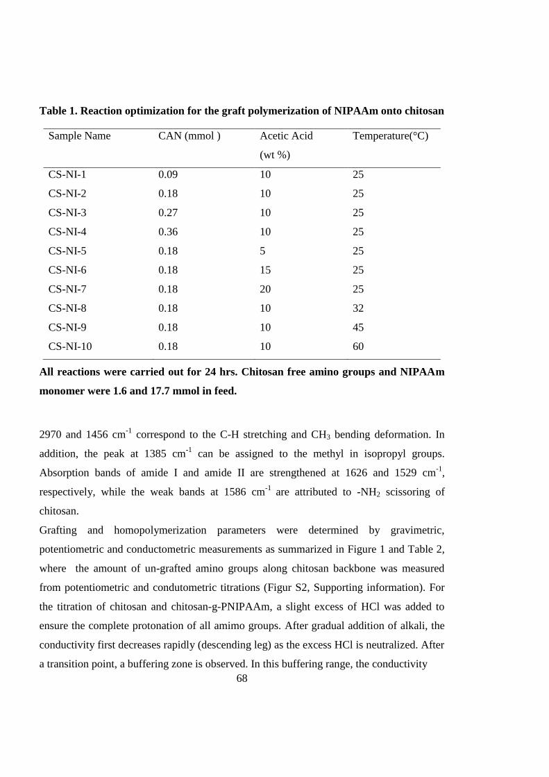
68
Table 1. Reaction optimization for the graft polymerization of NIPAAm onto chitosan
Sample Name CAN (mmol ) Acetic Acid
(wt %)
Temperature(°C)
CS-NI-1 0.09 10 25
CS-NI-2 0.18 10 25
CS-NI-3 0.27 10 25
CS-NI-4 0.36 10 25
CS-NI-5 0.18 5 25
CS-NI-6 0.18 15 25
CS-NI-7 0.18 20 25
CS-NI-8 0.18 10 32
CS-NI-9 0.18 10 45
CS-NI-10 0.18 10 60
All reactions were carried out for 24 hrs. Chitosan free amino groups and NIPAAm
monomer were 1.6 and 17.7 mmol in feed.
2970 and 1456 cm-1
correspond to the C-H stretching and CH3 bending deformation. In
addition, the peak at 1385 cm-1
can be assigned to the methyl in isopropyl groups.
Absorption bands of amide І and amide ІІ are strengthened at 1626 and 1529 cm-1
,
respectively, while the weak bands at 1586 cm-1
are attributed to -NH2 scissoring of
chitosan.
Grafting and homopolymerization parameters were determined by gravimetric,
potentiometric and conductometric measurements as summarized in Figure 1 and Table 2,
where the amount of un-grafted amino groups along chitosan backbone was measured
from potentiometric and condutometric titrations (Figur S2, Supporting information). For
the titration of chitosan and chitosan-g-PNIPAAm, a slight excess of HCl was added to
ensure the complete protonation of all amimo groups. After gradual addition of alkali, the
conductivity first decreases rapidly (descending leg) as the excess HCl is neutralized. After
a transition point, a buffering zone is observed. In this buffering range, the conductivity
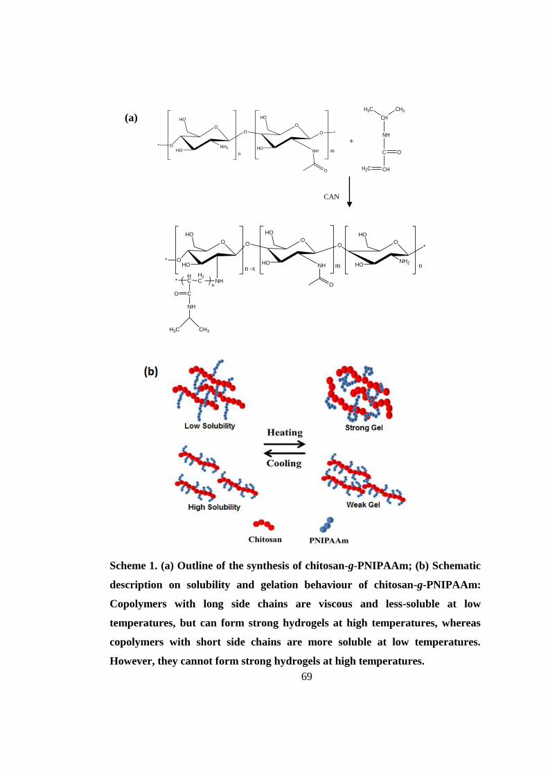
69
Scheme 1. (a) Outline of the synthesis of chitosan-g-PNIPAAm; (b) Schematic
description on solubility and gelation behaviour of chitosan-g-PNIPAAm:
Copolymers with long side chains are viscous and less-soluble at low
temperatures, but can form strong hydrogels at high temperatures, whereas
copolymers with short side chains are more soluble at low temperatures.
However, they cannot form strong hydrogels at high temperatures.
(a)
CAN
,
N2
24 h
+
O
OHO
NH2
HO
O
HO
O
HO
O
NH
*
*O
nm
H2C CH
C O
NH
CH
CH3H3C
O
OHO
HOO
HO
O
HO
O
NH*
O
NHH2C
HC
CO
NH
*n
O
HONH2
HO
*
n -x m n
H3C CH3

70
increases slowly with the alkali addition, as a consequence of the neutralization of the
protonated free amino groups. Therefore, this range can be used for the quantification of
the PNIPAAm side chains on chitosan backbone as they have substituted amino groups on
chitosan (39). A narrower buffering zone corresponds to the less availability of free –NH2
groups and more grafts on chitosan. After the second transition point, the conductivity
increases (ascending leg), indicating the introduction of excess NaOH. Similar steps are
distinguishable in potentiometric titration curves. The degrees of substitution were
calculated for each sample from the values of reacted and un-reacted functional groups
(free amino groups in this case) using Equation 3 (14, 39). The mechanisms for initiation,
propagation and termination of grafting polymerization are as follows:
Initiation:
CS Ce4 Complex CS Ce3 H (4)
M Ce4 M Ce3 H (5)
(6)
Propagation:
CSM nM CSM n 1 (7)
M nM M n 1 (8)
Termination:
CSM n M m (9)
M n M m Mn m (10)
CSM n CSM m - (11)
CSM n Ce4 CSMn Ce
3 H
(12)
M n Ce4 Mn Ce
3 H
(13)
CSM n M CSMn M (14)
CSM n P CSMn P (15)
where CS, M, Ce and P represent chitosan, NIPAAm monomer, ceric ion and propagating
polymers, respectively.

71
Figure S1. FTIR spectra of chitosan and chitosan-g-PNIPAAm (CS-NI-2)

72
Table 2. Summary of products synthesized at different reaction conditions
a Calculated from gravimetric measurements and Equation 1.
b Visually verified (Yes: gelation occurs with temperature rise, No: no gelation with temperature rise).
Parameter Sample
name
Percentage of
homo-
polymerization
(%)a
Yield
(%)a
Gelationb
Acid concentration
CS-NI-5 6 20 NO
CS-NI-2 27 61 Yes
CS-NI-6 27 66 Yes
CS-NI-7 28 73 Yes
CS-NI-2 27 61 Yes
Temperature
CS-NI-8 44 71 Yes
CS-NI-9 40 65 Yes
CS-NI-10 30 56 Yes
Initiator
concentration
CS-NI-1 9 20 NO
CS-NI-2 27 61 Yes
CS-NI-3 43 78 Yes
CS-NI-4 80 96 Yes
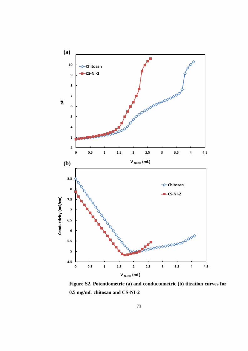
73
Figure S2. Potentiometric (a) and conductometric (b) titration curves for
0.5 mg/mL chitosan and CS-NI-2
(a)
(b)

74
3.4.1.1 Effect of initiator concentration
Based on Equations 4, 6 and 7, it is expected that grafting ratio and degree of substitution
increase by increasing initiator concentration. To investigate the influence of initiator feed
on grafting parameters, a range of polymerizations at various CAN concentrations from
0.09 to 0.36 mmol has been carried out. The results are shown in Figure 1a and Table 2.
The degree of substitution increases continuously with increasing the amount of CAN
initiator. It is expected that the more the initiator is fed, the more the free radical can be
formed on chitosan backbone, leading to more side graft chains (Equations 4 & 6). At a
low concentration of initiator (0.09 mmol), no grafting occurs and only the
homopolymerization of NIPAAm is found. The grafting ratio increases with the increment
of initiator concentration up to 0.18 mmol. On the other hand, the percentage of
homopolymer is increased simultaneously. Beyond this concentration, a further increase in
CAN lead to a slight drop in grafting ratios. That could be due to the increase in formation
of free radicals on chitosan, leading to more termination reactions by coupling these
radicals according to Equations 9,11,12,14 and 15 (36, 42, 43), while homopolymerization
increment is continued as a competitor reaction (Equations 5 & 8). Similar experimental
trend has also been observed by Lee et al. (36).
3.4.1.2 Effect of reaction temperature
Effect of reaction temperature on polymerization parameters was investigated between 25
to 0 C. As shown in Figure 1b and Table 2, the grafting ratio gradually decreases, but
the degree of substitution drastically increases with the increase of temperature. In
addition, it is observed that the percentage of homopolymerization increases with the
increament of temperature below the LCST, while it decreases when temperature keeps
rising above the LCST. At a low temperature below the LCST of PNIPAAm, the initiator
is less active and therefore offer less free radicals on chitosan amino groups and in
solution. However, the fully homogeneous system allows monomers to access to and react
with these free radicals easily. As a result, less grafts are found on the backbone, while
thier chain length are long. By increasing the temperature, the initiator is more active,

75
Figure 1. Effect of reaction parameters on grafting properties of chitosan-
g-NIPAAM, where filled squares indicate GR% and open circles show the
DS%. (a) Initiator concentration [acid concentration:10 wt%; reaction
temperature: 25˚ C and reaction time: 24 h] ; (b) reaction temperature
[initiator concentration: 0.1 mg; acid concentration:10 wt% and reaction
time: 24 h]; (c) acetic acid concentration [initiator concentration: 0.1 mg;
reaction temperature: 25˚ C and reaction time: 24 h].
a

76
leading to more substitutions and homopolymers. However, the increased rate of
termination reduces the grafting ratio. When the temperature is close or over the LCST,
thermo-reversible phase transition of grafted chains and homopolymers occurs. The
solution turns from a water-soluble hydrophilic state to a water-insoluble hydrophobic
state. Thus, the system is likely heterogeneous which ultimately affects the penetration and
diffusion of NIPAAm monomers into the active sites on the chitosan and homopolymer
radicals (43). Therefore, more substitution and less grafting ratio on chitosan backbone
together with low percentage of hopolymer are expected.
3.4.1.3 Effect of acetic acid concentration
During the synthesis, it is also found that the amount of acetic acid applied to prepare
chitosan aqueous solution in the reaction system has significant effect on grafting
parameters. Therefore, this effect was systematically studied at different acetic acid
concentrations ranging from 5 to 20 wt% with experimental results shown in Figure 1c
and Table 2.
Initially, an increase in acetic acid concentration from 5 to 10 wt% results in increasing
both the grafted and homopolymerized NIPAAm. The degree of substitution shows a
significant drop over this acid concentration range. By further increasing acetic acid
concentration, no significant effect on grafting parameters is observed. At low H+
concentrations, a high degree of substitution and a low grafting ratio suggest more grafts
with shorter chain lengths. It is attributed to the initiation Equations of 4 and 5, which are
more favorable at low H+ concentrations (42). At a higher acid concentration, high H
+
concentration leads to less initiation and subsequently less growing chains on chitosan
backbone. Simultaneousely, termination reactions get less favorable ( Equations 12 & 13),
which promote longer chain formation.
3.4.2 Solubility
Although the solubility of an injectable hydrogel is an important parameter, no
comprehensive study has been reported on the solubility of chitosan-g-PNIPAAm yet. The

77
solubility of various copolymers was investigated by measuring the turbidity of polymer
solutions against pH. Figure 2 demonstrates the pH-responsiveness of the grafting
copolymers in comparison with chitosan. At low pH, all samples showed no significant
change in their solubilities. However, the turbidity of each solution dropped dramatically at
a certain pH, which indicates phase separation.
The plot reveals that by increasing the initiator concentration from 0.18 mmol for CS-NI-2
to 0.36 mmol for CS-NI-4, the pH-solubility profile is extended and the precipitation
points elevate from pH ≈ 5.2 to pH ≈ 6.5. The solubility of chitosan in aqueous solution is
governed by two main factors: protonation of free amino groups which results in
interruption of intermolecular hydrogen bonds and hence improves solubility; and inter-
Figure 2. Solubility of chitosan and various chitosan-g-PNIPAAm samples at different
pHs as measured by the turbidity of 0.44 mg mL-1
polymer solutions at 600 nm.
20.0
30.0
40.0
50.0
60.0
70.0
80.0
90.0
100.0
2 3 4 5 6 7 8
Tran
smit
tan
ce (
%)
pH
CS-NI-8
CS-NI-5
CS-NI-4
CS-NI-2
Chitosan

78
chain crystallinity which reduces the solubility. An increase in the initiator leads to a
higher degree of substitution and results in less free amino groups along chitosan backbone
( See section 3.4.1.1 ). As a result, the remaining amino groups need less protons for
protonation, which could be provided at higher pHs. Moreover, these grafts can destroy the
crystallinity and further improve water solubility.
Reducing the acetic acid concentration in the reaction solution for CS-NI-5 (5 wt%) results
in a broader solubility window with an onset at pH ≈ 6.1 in comparison with CS-NI-2 (10
wt%), which is due to its higher degree of substitution (See section 3.4.1.3 ).
Precipitation at higher pHs was observed for the CS-NI-8 synthesized at 32 °C compared
to CS-NI-2 (prepared at 25°C), which is in agreement with its higher graft numbers (See
section 3.4.1.2 ). A decrease in turbidity of the stable phase (low pH) might be attributed to
the non-homogeneous reaction condition that the polymerization temperature close to the
LCST of PNIPAAm. More growing side chains on the chitosan backbones result in higher
chance of self-crosslinking.
3.4.3 Rheological measurements
Mechanical properties of stem cells niche are known to modulate their fates along with the
chemical and biophysical properties of the microenvironement. Cell mechano-sensitive
pathways translate these cues into biochemical signals that guide the cell to a specific
lineage or behaviour (44-46). Therefore, it is extremely important to control the
mechanical properties such as elasticity when designing a biomaterial to mimic the 3D
microenvironement for stem cells.
To investigate the viscoelastic characteristics of chitosan-g-PNIPAAm solution at different
temperatures before and after gelation, we have conducted dynamic mechanical analysis.
At low temperatures (20-30˚C), loss modulus (G”) dominates the flow property and the
value of storage modulus (G’) is too small to be accurately measured, as shown in Figure
3b. This corresponds to the solution state of the samples. In this temperature range, the loss
modulus decreases slightly with an increase in the temperature due to thermal movement
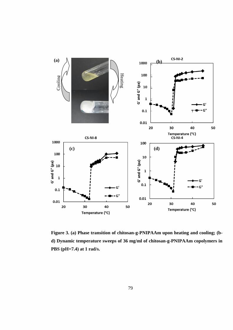
79
(a) (b) C
ooli
ng
Heatin
g
+
(d) (c)
Figure 3. (a) Phase transition of chitosan-g-PNIPAAm upon heating and cooling; (b-
d) Dynamic temperature sweeps of 36 mg/ml of chitosan-g-PNIPAAm copolymers in
PBS (pH=7.4) at 1 rad/s.
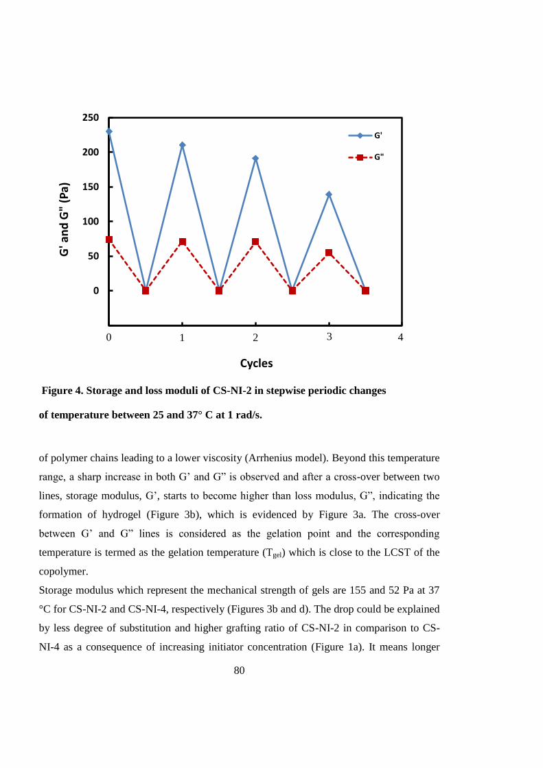
80
Figure 4. Storage and loss moduli of CS-NI-2 in stepwise periodic changes
of temperature between 25 and 37° C at 1 rad/s.
of polymer chains leading to a lower viscosity (Arrhenius model). Beyond this temperature
range, a sharp increase in both G’ and G” is observed and after a cross-over between two
lines, storage modulus, G’, starts to become higher than loss modulus, G”, indicating the
formation of hydrogel (Figure 3b), which is evidenced by Figure 3a. The cross-over
between G’ and G” lines is considered as the gelation point and the corresponding
temperature is termed as the gelation temperature (Tgel) which is close to the LCST of the
copolymer.
Storage modulus which represent the mechanical strength of gels are 155 and 52 Pa at 37
°C for CS-NI-2 and CS-NI-4, respectively (Figures 3b and d). The drop could be explained
by less degree of substitution and higher grafting ratio of CS-NI-2 in comparison to CS-
NI-4 as a consequence of increasing initiator concentration (Figure 1a). It means longer
-50
0
50
100
150
200
250
1 3 5 7 9
G' a
nd
G"
(Pa)
Cycles
G'
G"
4
0 3 2 1

81
side chain lengths on chitosan backbone in CS-NI-2 could improve polymer chain
entanglements and hence make the gels stronger.
Sample CS-NI-5 synthesized in 5 wt% acid does not show a phase transition with rise in
temperature (Table 2). However, CS-NI-2 synthesized at 10 wt% acid undergoes a sol-gel
transition and forms a relatively strong gel. It happens due to the very low grafting ratio
and high degree of substitution (Figure 1c), which results in very short side chain lengths
in CS-NI-5.
An increment in reaction temperature from 25 °C (CS-NI-2) to 32°C (CS-NI-8) results in
the decrease in gel mechanical strength from 155 Pa to 30 Pa at 37 °C (Figures 3b and c).
GR and DS in Figure 1b can be used to explain the decrease of mechanical strength.
Increasing the reaction temperature makes more, but shorter PNIPAAm side chains on
chitosan and consequencely gels are weaker.
To examine the reversibility of the sol-gel transition behaviour, several cycles of stepwise
temperature change between 25 and 37˚C were applied and the mechanical modulus were
monitored. As shown in Figure 4, the copolymer reveals a thermo-reversible behaviour.
However, the storage modulus slightly decreases over cycles. After cooling the hydrogel,
without any stirring, the solution is not a homogeneous liquid as it was before the first
gelation. Therefore, when the solution is warmed up again, the structure could not regain a
uniform network of hydrogel, resulting in a weaker hydrogel at further cycles.
3.4.4 Morphological studies
The microstructure of the hydrogel was studied using a scanning electron microscopy.
Figure 5 presents the SEM micrographs of the hydrogel cross-sections. These images
demonstrate the interconnected porous structure of the hydrogel which provides adequate
space for nutrient delivery to cells and waste removal from their microenvironment as well
as supports cell proliferation and migration.

82
3.4.5 In vitro three-dimensional cell culture
To investigate the interactions between MSCs and the hydrogel microenvironment, the
MTT assays were employed. Cell viability was monitored over a 14 day period. Figure 6
shows the optical densities obtained from the MTT assays, which represent the number of
viable cells. The results reveal that cells retain their biological activities and gradually
proliferate inside the hydrogel during the first 7 days of cultivation, and after that, the cell
number ceases to increase. However, cells remain metabolically active at day 14 as
evidenced by the optical density, which is nearby the same as day 7. When cells are
cultured in a 3D microenvironment, the cell viability and metabolic activity depend on
several parameters including cell type, cell-seeding density and the surrounding material.
Cardiac cells showed a constant number of viable cells within alginate hydrogel regardless
of seeding density while proliferated significantly on 2D culture dishes (47). The same
trend has been reported for the viability of osteoblasts encapsulated in Arg-Gly-Asp
(b) (a)
Figure 5. SEM micrograph of (a) chitosan-g-PNIPAAM (CS-NI-2) hydrogel and (b) the
enlarged section of marked area in a.

83
Figure 6. MSCs proliferation cultured in chitosan-g-PNIPAAm (CS-NI-2) hydrogels
(red bars) and monolayers (green bars) measured by MTT assays. (n=3, Mean± SE)
(RGD)-modified poly (ethylene glycol) hydrogels (48). Hepatocytes entrapped in alginate
scaffolds lost 66% of their metabolic activity within 7 days when seeded at the cell density
of 0.28x10⁶ cells.cm
-3 scaffold. However, they maintained their viability when cultured at
an initial seeding density of 18.2x10⁶
cells.cm-3
after a 25% decrease within the first 24h
(49). MSC metabolic activity decreased up to day 3 when cultured within chitosan/alginate
polyelectrolyte complex-based scaffolds and then showed an slight increase until day 14
(50). In comparison with 2D cell culture, the number of MSCs is less in the 3D chitosan-g-
PNIPAAm hydrogel. However, cell proliferation is observed from Figure 6 and the cellular
biomass reaches a plateau after 7 days. The dynamic balance of cell number inside the
hydrogel is due to insufficient oxygen and nutrient supplied to cells and lack of space when
a certain cell density is reached. The cell survival is significantly improved through
0.0
0.5
1.0
1.5
2.0
2.5
3.0
1 4 7 14
Op
tica
l Den
sity
(O
.D)
Day
CS-NI
Monolayer

84
manipulation of hydrogel properties; while the decreased cell viability of osteoblasts (36)
and MSCs (37) have been reported when cells were cultured within the same hydrogel
without manipulation. The retaining of cell viability is essential for downstream processing
steps. For example, in the in vivo injection of cell-laden hydrogels to cure tissue damages,
cells must be able to survive in human body environment so that cells can play their
therapeutic roles. In tissue engineering applications using stem cells and hydrogels, cells
need to keep viable during cell differentiation process. The preliminary results have
demonstrated that the synthesized chitosan-g-PNIPAAm hydrogel with manipulated
properties can support cell proliferation and retain cell viability for up to 14 days.
Figure 7 shows confocal laser scanning images of cells inside the hydrogel. Live and dead
cells were stained in green and red, respectively. An increase in green intensity from day 1
(a-c) to day 7 (d-f) corresponds to cell number increment and also cell spread morphology.
It verifies cell viability and proliferation during the seven-day period. However, the higher
green intensity is not just implied by cell number. It is also partially due to cells’
elongation and even some aggregations (48). These results are consistent with the MTT
values. At day 1, more dead cells (red spots) could be observed in comparison with day 7
and the cell death at day 1 may be explained as a consequence of the first shock when cells
adapting them with a new culture microenvironment. In order to determine cell distribution
inside the hydrogel, images were taken at the different heights of 40, 80 and 120 μm above
the bottom of the microwell plate, and images c & f, b & e and a & d (in Figure 7) were
corresponding to three scans respectively. The images demonstrate that cells retained their
viability and well distributed within the hydrogel, all through the different depths of the
hydrogel inside the microwell, not on the top of the gel or at the bottom of the wells. Cell
morphology at day 1 (Figure 7g) and day 7 (Figure 7h) can be observed from high-
magnification (60×) images. Cells appear to be in a round shape at day 1 (Figure 7g), when
there are still not strong cell-matrix interactions. In contrast, at day 7, cells lose their
spherical shape and change to a spread or elongated structure in a 3D manner. This change
might be due to cellular adaptation to the porous and interconnected microenvironment
which encourages cells to attach to the surface of the pores and conform to the shape of the
available lacuna. Cells start to grow and remain close to each other to impart cell-cell

85
Figure 7. Confocal laser scanning images of MSCs cultured in chitosan-g-
PNIPAAm (CS-NI-2) hydrogels:
(a-f): Comparison on cell densities at day 1 (a-c) and day 7 (d-f). Images were
taken at different distances (a, d = 120 μm; b, e = 80 μm and c, f = 40 μm)
from the bottom of the samples. 10X oil immersion objective. Scale bars are
250 μm.
(g, h): Z-series of images captured at high magnification (63X oil immersion
objective) and converted to 3D images using the Volocity ™ software, at day
1 (g) and 7(h). Scale bars are 16 μm.
(i): Harvested cells after melting down the mixed hydrogels at day 7. 20X oil
immersion objective. Scale bar is 100 μm.
1
a
b
c
d
e
f
g
h
i
40μm
40μm
40μm

86
interactions. They overlap inside the pore structure and individual cells are not easily
distinguishable. However, spherical individual cells can be observed to be resuspended in
the solution when the hydrogel converts to solution after reducing the temperature to an
ambient one, which is shown in Figure 7i. The recovered cells can be re-cultured onto the
2D rigid surface, which means the cells are viable and can retain their migration capacity
as well.
3.5 Conclusions
In this study, chitosan-g-poly(N-isopropylacrylamide) was synthesized as a thermo-
responsive hydrogel. The synthesized polymer showed a thermo-reversible sol-gel
transition behaviour at around 32˚C. It has been demonstrated that the solubility of
copolymer aqueous solutions and mechanical strength of their gels could be manipulated
by the number and length of PNIPAAm grafts which have been substituted with free
amino groups on chitosan backbone. To control the graft ratio and chain length, the effect
of polymerization conditions, including acid concentration, reaction temperature and
initiator concentration on the degree of substitution and grafting ratio have been
systematically investigated. SEM observations revealed the porous structure of the
hydrogel which can facilitate oxygen and nutrient delivery to cells and cell growth.
Mesenchymal stem cells were cultured in CS-g-PNIPAAm hydrogels. Cell viability and
proliferation were evaluated by the MTT assay. It was demonstrated that cells retained
their biological activities. Confocal images confirmed the cell viability and proliferation
and uniform distribution inside the hydrogel while their phenotypic morphology was
preserved. These results reinforce the suitability of chitosan-g-poly(N-
isopropylacrylamide) copolymer as a well-controlled microenvironement for cells,
especially stem cells and its potential applications in 3D cell culture, tissue engineering
and regenerative medicine.

87
3.6 References
1. Zhang H, Dai S, Bi J, Liu KK. Biomimetic three-dimensional microenvironment
for controlling stem cell fate. Interface Focus. 2011;1(5):792-803.
2. Van Vlierberghe S, Dubruel P, Schacht E. Biopolymer-based hydrogels as
scaffolds for tissue engineering applications: a review. Biomacromolecules.
2011;12(5):1387-408.
3. Drury JL, Mooney DJ. Hydrogels for tissue engineering: scaffold design variables
and applications. Biomaterials. 2003;24(24):4337-51.
4. Hoffman AS. Hydrogels for biomedical applications. Adv Drug Del Rev.
2002;54(1):3-12.
5. Baroli B. Hydrogels for tissue engineering and delivery of tissue-inducing
substances. J Pharm Sci. 2007;96(9):2197-223.
6. Liu F, Urban MW. Recent advances and challenges in designing stimuli-responsive
polymers. Prog Polym Sci. 2010;35(1):3-23.
7. Mano JF. Stimuli-Responsive Polymeric Systems for Biomedical Applications.
Adv Eng Mater. 2008;10(6):515-27.
8. Alarcon CdlH, Pennadam S, Alexander C. Stimuli responsive polymers for
biomedical applications. Chem Soc Rev. [10.1039/B406727D]. 2005;34(3):276-85.
9. Klouda L, Mikos AG. Thermoresponsive hydrogels in biomedical applications.
European Journal of Pharmaceutics and Biopharmaceutics. 2008;68(1):34-45.
10. Yu L, Ding J. Injectable hydrogels as unique biomedical materials. Chem Soc Rev.
2008;37(8):1473-81.
11. Jeong B, Kim SW, Bae YH. Thermoresponsive sol–gel reversible hydrogels. Adv
Drug Del Rev. 2012.
12. Fedorovich NE, Alblas J, de Wijn JR, Hennink WE, Verbout AJ, Dhert WJ.
Hydrogels as extracellular matrices for skeletal tissue engineering: state-of-the-art and
novel application in organ printing. Tissue Eng. 2007;13(8):1905-25.
13. Gutowska A, Jeong B, Jasionowski M. Injectable gels for tissue engineering. The
Anatomical Record. 2001;263(4):342-9.
88
14. Shen Z, Bi J, Shi B, Nguyen D, Xian CJ, Zhang H, et al. Exploring thermal
reversible hydrogels for stem cell expansion in three-dimensions. Soft Matter.
2012;8(27):7250-7.
15. Shen Z, Mellati A, Bi J, Zhang H, Dai S. A thermally responsive cationic nanogel-
based platform for three-dimensional cell culture and recovery. RSC Advances.
2014;4(55):29146-56.
16. Di Martino A, Sittinger M, Risbud MV. Chitosan: A versatile biopolymer for
orthopaedic tissue-engineering. Biomaterials. 2005;26(30):5983-90.
17. Hirano S, Tsuchida H, Nagao N. N-acetylation in chitosan and the rate of its
enzymic hydrolysis. Biomaterials. 1989;10(8):574-6.
18. Freier T, Koh HS, Kazazian K, Shoichet MS. Controlling cell adhesion and
degradation of chitosan films by N-acetylation. Biomaterials. 2005;26(29):5872-8.
19. Rabea EI, Badawy ME-T, Stevens CV, Smagghe G, Steurbaut W. Chitosan as
antimicrobial agent: applications and mode of action. Biomacromolecules.
2003;4(6):1457-65.
20. Zheng LY, Zhu JF. Study on antimicrobial activity of chitosan with different
molecular weights. Carbohydr Polym. 2003;54(4):527-30.
21. Ueno H, Mori T, Fujinaga T. Topical formulations and wound healing applications
of chitosan. Adv Drug Del Rev. 2001;52(2):105-15.
22. Rzaev ZM, Dincer S, Pişkin E. Functional copolymers of N-isopropylacrylamide
for bioengineering applications. Prog Polym Sci. 2007;32(5):534-95.
23. Kim SY, Cho SM, Lee YM, Kim SJ. Thermo‐and pH‐responsive behaviors of
graft copolymer and blend based on chitosan and N‐isopropylacrylamide. J Appl Polym
Sci. 2000;78(7):1381-91.
24. Lee WF, Chen YJ. Studies on preparation and swelling properties of the
N‐isopropylacrylamide/chitosan semi‐IPN and IPN hydrogels. J Appl Polym Sci.
2001;82(10):2487-96.
25. Chen X, Song H, Fang T, Bai J, Xiong J, Ying H. Preparation, characterization, and
drug‐release properties of pH/temperature‐responsive poly

89
(N‐isopropylacrylamide)/chitosan semi‐IPN hydrogel particles. J Appl Polym Sci.
2010;116(3):1342-7.
26. da Silva RM, López‐Pérez PM, Elvira C, Mano JF, Román JS, Reis RL. Poly
(N‐isopropylacrylamide) surface‐grafted chitosan membranes as a new substrate for
cell sheet engineering and manipulation. Biotechnol Bioeng. 2008;101(6):1321-31.
27. Wang J, Chen L, Zhao Y, Guo G, Zhang R. Cell adhesion and accelerated
detachment on the surface of temperature-sensitive chitosan and poly (N-
isopropylacrylamide) hydrogels. J Mater Sci Mater Med. 2009;20(2):583-90.
28. Don TM, Chou SC, Cheng LP, Tai HY. Cellular compatibility of copolymer
hydrogels based on site‐selectively‐modified chitosan with poly (N‐isopropyl
acrylamide). J Appl Polym Sci. 2011;120(1):1-12.
29. Lee SB, Ha DI, Cho SK, Kim SJ, Lee YM. Temperature/pH‐sensitive
comb‐type graft hydrogels composed of chitosan and poly (N‐isopropylacrylamide). J
Appl Polym Sci. 2004;92(4):2612-20.
30. Don T-M, Chen H-R. Synthesis and characterization of AB-crosslinked graft
copolymers based on maleilated chitosan and N-isopropylacrylamide. Carbohydr Polym.
2005;61(3):334-47.
31. Chuang CY, Don TM, Chiu WY. Preparation of environmental-responsive
chitosan-based nanoparticles by self-assembly method. Carbohydr Polym. 2011;84(2):765-
9.
32. Sanoj Rejinold N, Sreerekha P, Chennazhi K, Nair S, Jayakumar R. Biocompatible,
biodegradable and thermo-sensitive chitosan-g-poly (N-isopropylacrylamide) nanocarrier
for curcumin drug delivery. Int J Biol Macromol. 2011;49(2):161-72.
33. Sundaresan V, Menon JU, Rahimi M, Nguyen KT, Wadajkar AS. Dual-responsive
polymer-coated iron oxide nanoparticles for drug delivery and imaging applications. Int J
Pharm. 2014;466(1):1-7.
34. Gui R, Wang Y, Sun J. Embedding fluorescent mesoporous silica nanoparticles
into biocompatible nanogels for tumor cell imaging and thermo/pH-sensitive in vitro drug
release. Colloids Surf B Biointerfaces. 2014;116:518-25.
90
35. Wang Y, Wang J, Ge L, Liu Q, Jiang L, Zhu J, et al. Synthesis, properties and
self‐assembly of intelligent core‐shell nanoparticles based on chitosan with different
molecular weight and N‐isopropylacrylamide. J Appl Polym Sci. 2013;127(5):3749-59.
36. Lee J, Jung M, Park H, Park K, Ryu G. Synthesis and characterization of
thermoresponsive chitosan copolymer as a novel biomaterial. Journal of Biomaterials
Science, Polymer Edition. 2004;15(8):1065-79.
37. Cho JH, Kim S-H, Park KD, Jung MC, Yang WI, Han SW, et al. Chondrogenic
differentiation of human mesenchymal stem cells using a thermoresponsive poly (N-
isopropylacrylamide) and water-soluble chitosan copolymer. Biomaterials.
2004;25(26):5743-51.
38. Cao Y, Zhang C, Shen W, Cheng Z, Yu LL, Ping Q. Poly (N-isopropylacrylamide)
– chitosan as thermoresponsive in situ gel-forming system for ocular drug delivery. J
Controlled Release. 2007;120(3):186-94.
39. Recillas M, Silva LL, Peniche C, Goycoolea FM, Rinaudo M, Argu elles-Monal
WM. Thermoresponsive behavior of chitosan-g-N-isopropylacrylamide copolymer
solutions. Biomacromolecules. 2009;10(6):1633-41.
40. Chen JP, Cheng TH. Thermo‐Responsive Chitosan‐graft‐poly
(N‐isopropylacrylamide) Injectable Hydrogel for Cultivation of Chondrocytes and
Meniscus Cells. Macromol Biosci. 2006;6(12):1026-39.
41. Chen C, Liu M, Gao C, Lü S, Chen J, Yu X, et al. A convenient way to synthesize
comb-shaped chitosan-graft-poly (N-isopropylacrylamide) copolymer. Carbohydr Polym.
2013;92(1):621-8.
42. McDowall D, Gupta B, Stannett V. Grafting of vinyl monomers to cellulose by
ceric ion initiation. Prog Polym Sci. 1984;10(1):1-50.
43. Gupta K, Khandekar K. Temperature-responsive cellulose by ceric (IV) ion-
initiated graft copolymerization of N-isopropylacrylamide. Biomacromolecules.
2003;4(3):758-65.
44. Reilly GC, Engler AJ. Intrinsic extracellular matrix properties regulate stem cell
differentiation. J Biomech. 2010;43(1):55-62.

91
45. Engler AJ, Sen S, Sweeney HL, Discher DE. Matrix Elasticity Directs Stem Cell
Lineage Specification. Cell. 2006;126(4):677-89.
46. Discher DE, Mooney DJ, Zandstra PW. Growth Factors, Matrices, and Forces
Combine and Control Stem Cells. Science. 2009 June 26, 2009;324(5935):1673-7.
47. Dar A, Shachar M, Leor J, Cohen S. Optimization of cardiac cell seeding and
distribution in 3D porous alginate scaffolds. Biotechnol Bioeng. 2002;80(3):305-12.
48. Burdick JA, Anseth KS. Photoencapsulation of osteoblasts in injectable RGD-
modified PEG hydrogels for bone tissue engineering. Biomaterials. 2002;23(22):4315-23.
49. Dvir-Ginzberg M, Gamlieli-Bonshtein I, Agbaria R, Cohen S. Liver tissue
engineering within alginate scaffolds: effects of cell-seeding density on hepatocyte
viability, morphology, and function. Tissue Eng. 2003;9(4):757-66.
50. Ceccaldi C, Bushkalova R, Alfarano C, Lairez O, Calise D, Bourin P, et al.
Evaluation of polyelectrolyte complex-based scaffolds for mesenchymal stem cell therapy
in cardiac ischemia treatment. Acta Biomater. 2014;10(2):901-11.

92

93
CHAPTER FOUR
Microengineered 3D Cell-laden Thermoresponsive 4.
Hydrogels as a Platform for Bi-zonal Cartilage Tissue
Engineering Using Mesenchymal Stem Cells

94
95
Microengineered 3D cell-laden thermoresponsive hydrogels as a
platform for bi-zonal cartilage tissue engineering using
mesenchymal stem cells
Amir Mellatia, Chia-ming Fan
b, Ali Tamayol
c, Sheng Dai
a, Jingxiu Bi
a, Bo Jin
a,
Cory Xianb, Ali Khademhosseini
c,d,e, Hu Zhang
a*
aSchool of Chemical Engineering, the University of Adelaide, Adelaide SA 5005, Australia
b Sansom Institute for Health Research, School of Pharmacy and Medical Sciences,
University of South Australia, Adelaide, SA 5001, Australia
c Center for Biomedical Engineering, Department of Medicine, Brigham and Women’s
Hospital, Harvard Medical School, Boston, MA 02139, USA
d Harvard-MIT Division of Health Sciences and Technology, Massachusetts Institute of
Technology, Cambridge, MA 02139, USA
e Wyss Institute for Biologically Inspired Engineering, Harvard University, Boston, MA
02115, USA
*Corresponding author
E-mail: [email protected]
Tel: + 61 8 8313 3810

96
4.1 Abstract
Engineering the articular cartilage with the same zonal organization as the native tissue
remains a great challenge for tissue engineering. In this study, we employed a
micropatterning technique to mimic the cellular shape and orientation within the
superficial and middle zone of the natural cartilage. Chitosan-g-poly(N-
isopropylacrylamide) (CS-g-PNIPAAm) was synthesized as a thermresponsive copolymer
and mesenchymal stem cells were incoporated within the CS-g-PNIPAAm hydrogel.
Biochemical assays show 6 and 7 fold increment in glycosaminoglycans and total collagen
at 28 day incubation in chondrogenic medium, respectively. Chondrogenic differentiation
was also verified qualitatively by histological and immunohistochemical assessments.
Three-dimensional micropatterned cell-laden hydrogels were fabricated using
poly(ethylene glycol) dimethacrylate micromolds. Within the 50 µm wide microconstructs,
75 ± 6% of cells are oriented with an aspect ratio of 2.075 ± 0.161 at day 5, which is the
highest level of cell alignment and elongation, and much greater than those (12 ± 7%
alignment and a shape index of 1.202 ± 0.07) of the unpatterned constructs. The highly
oriented microconstruct was used for mimicing the cell shape and organization in the
superficial zone cartilage while the unpatterned one for middle zone. Our results suggest
that micropatterning of 3D cell-laden thermoresponsive hydrogels is a promising platform
for multi-zonal cartilage tissue engineering.
97
4.2 Introduction
Articular cartilage is a thin layer of hyaline cartilage covering the bone heads of
articulating joints that permits smooth motion between adjoining bony segments (1). It is a
multiphasic tissue consisting of chondrocyte cells, interstitial fluid and extracellular matrix
(ECM) mainly composed of collagen fibres and proteoglycans (PG) (2). Three important
zones or layers are distinguishable in articular cartilage as shown in Scheme 1a (3). The
closest layer to the cartilage surface is termed as superficial zone where chondrocytes are
ellipsoidal and parallel to the surface. The middle or transitional zone is laid under the
superficial zone. Chondrocytes are rounder in comparison to the superficial zone and they
are randomly aligned. The deep zone is below the middle layer. Chondrocytes are spherical
in shape and are aligned columnar and perpendicular to the tidemark (4-6). Each layer has
its specific mechanical properties and biochemical composition.
Cartilage-related diseases such as arthritis are the most common reasons for giving rise to
disabilities around the world (7). Daily accidents may also damage this soft tissue.
Unfortunately, articular cartilage has limited self-repair potential (8). Among various
therapeutic strategies to repair a damaged articular cartilage, tissue engineering is one of
the most appealing approaches. However, many challenges remain to be resolved in this
technique, including selecting an appropriate cell source and a matrix as well as recreating
the zonal organisation. Various cell sources can be used in cartilage tissue engineering,
including chondrocytes as cartilage-specific adult cells, embryonic stem cells (ESCs),
induced pluripotent stem cells (iPS) or adult stem cells such as mesenchymal stem cells
(MSCs) (9). MSCs are considered as an attractive candidate because of their ease of
isolation, in vitro expansion, and differentiation into cartilage (10). Interestingly, MSCs
can be differentiated to zonal chondrocytes in a suitable microenvironment (11). A variety
of artificial matrices have been explored for cartilage tissue engineering, and hydrogels are
one of the most suitable choices due to their similarity to the natural ECM of the cartilage
which is a highly hydrated tissue (12). Chitosan-based hydrogels have great potential to
enhance chondrogenesis and to modulate the chondrocyte morphology, differentiation and
98
function because of its structure similar to glycosaminoglycans (GAGs) and hyaluronic
acid in PGs of native articular cartilages (13-16).
Recreating the aforementioned spatially-zoning organization of the native articular
cartilage is the most challenging. This complex zonal organization supports cartilage
functions within body joints (17). Various strategies (i.e cell-, matrix-, bioreactor- and
bioactive molecule-based) have been employed by researchers to mimic the layered
articular cartilage. In cell-based approaches, incorporation of different zonal chondrocytes
in a depth-dependent fashion within either a single layer (18) or multilayered hydrogel of
the same material (19, 20) was found to have a potential to recreate biomimetic zones.
Furthermore, Bhumiratana et al. showed that condensed mesenchymal cell bodies and their
fusion into homogeneous cellular aggregates (21) resulted in a stratified structure of the
articular cartilage. Matrices have also been manunipulated to recapitulate the organized
zonal architecture of the native cartilage. Encapsulation of MSCs (22, 23) or chondrocytes
(24, 25) in a layered hydrogel made of the same material (26) or in the spatially
composition-varying matrix displayed encouraging results. Other matrix-based strategies
include depth-dependent regulation of the physical and mechanical properties by altering
gel concentration (27), degradability (28), pore size through bioprinting (29), nanofiber
size and orientation (6, 17), nanoparticle concentration (30) or combinatorial scaffold
morphologies (e.g. electrospun poly(caprolactone) (PCL) fibers on top and porous PCL
scaffold in bottom) (31). Bioreactors have also been exploited to stimulate the cell-seeded
constructs by mechanical or chemical gradients (32-35). Gradient delivery of bioactive
molecules or nutrients such as oxygen (36) and glucose (37) is the fourth approach. In
addition, the combination of various approaches may enhance the zonal variation similar to
the inhomogeneity of the native cartilage. Thorpe et al. reported that manipulation of
oxygen tension and mechanical cues over the depth of cell-laden constructs to mimic the
zones of the cartilage by controlling MSC differentiation (38). Zonal chondrocytes in poly
(ethylene glycol)-based (PEG) hydrogels containing exogenous type I collagen, hyaluronic
acid (HA), or chondroitin sulfate (CS) at different layers demonstrated zone-dependent
cellular responses (39). While some of these sterategies have been focous on regenerating
the zone-specific ECM biochemical composition at a molecular level, or on mimicking the

99
zone-specific mechanical properties, other efforts have been made to resemble the layered
physical microarchitecture of the native cartilage, such as celluralr shape and arrangement.
Micropatterning might be potentially an alternative apporoach for mimicking the
microstructural organisation of cartilage zones. Micropatterning is a microfabrication
method based on soft lithography. It has been demonstrated that micropatterning is an
effective method for cell alignment and elongation in 2D or 3D (40). As zonal
chondrocytes were required to be kept in a 3D microenvironment to preserve or restore
their zone-specific characteristics (41), thus a 3D micropatterned construct would be
needed for engineering different zones of the cartilage. Although UV curing of
photocrosslinkable hydrogels is the most popular approach in microfabrication of 3D cell-
encapsulated patterned constructs, UV irradiation as well as UV-induced free radicals
during the crosslinking process can potentially bring damage to the cells inside the
constructs (42, 43) or alter cell characteristics and functionalities. Cell viability is highly
dependent on UV exposure time and photoinitiator concentration (43) which are critical
parameters in regulation of gel physical and mechanical properties as well. As a
consequence, preparation of such constructs with optimum properties might be sacrificed
by reduced cell viability. Thermoresponsive hydrogels can be an alternative to form the
constructs with temperature change rather than UV curing. Thermoresponsive polymers
have attracted a lot of interest in 3D cell culture and differentiation due to ease of cell
distribution and instant cell release. These polymers have been also widely used to prepare
thermo-responsive microengineered platforms which could be exploited for 2D patterned
cell culture and co-culture (44), co-cultured cell sheets (45), patterned cell layers (46) and
cell aggregates from responsive microwells (47). These constructs were prepared through
the modified thermoresponsive surface of the substrates and templates. Switchable and
dynamic properties of these constructs can facilitate cultivation and detachment of cells
and microtissues. However, there are few reported studies on 3D constructs based on
thermoresponsive polymers. In one recent report, thermoresponsive polymers were used
for fabricating micromolds and cell-embedded agarose was cast in the micromolds for
sequential micropatterns (48).

100
In this study, we first diferentiated mesenchymal stem cells into chondrocytes in a
thermoresponsive polymer structure in 3D based on chitosan-g-poly(N-
isopropylacrylamide) (CS-g-PNIPAAm). The cell-laden copolymer was then cast into
micropatterns generated from PEG-DMA as a template to mimic cellular morphology and
orientation within the superficial zone of the native articular cartilage. Our results suggest
that the microengineered 3D cell-laden CS-g-PNIPAAm can offer great promise in bi-
zonal cartilage tissue engineering.
4.3 Materials and methods
4.3.1 CS-g-PNIPAAm synthesis and characterization
CS-g-PNIPAAm was synthesized by free radical grafting polymerization as described in
our recent work (49). Briefly, N-Isopropylacrylamide (NIPAAm) (Sigma-Aldrich, MO,
USA) was purified by recrystallization in n-hexane, and then 1 wt% chitosan (MW of 200-
300 kDa) (Acros Organic, NJ, USA) in 30 mL aqueous acetic acid (10 wt%) was mixed
with 17.7 mmol purified NIPAAm monomer and the mixture was degassed.
Polymerization was initiated by adding 0.18 mmol ammonium cerium (IV) nitrate (CAN)
(Acros Organic, NJ, USA) and reaction was carried out for 24 h under nitrogen
atmosphere. The solution was condensed and precipitated in an excess amount of
tetrahydrofuran/hexane (4:1). The precipitate was further purified by methanol soxhelet
extraction for 48 h. The purified product was dried under vacuum. Two products (CS-NI-1
and CS-NI-2) with different properties were obtained at the polymerisation temperature of
60 °C and 25 °C, respectively. Rheological measurement was conducted using a SR5
controlled stress rheometer (Rheometric Scientific, USA) as described before (49).
4.3.2 3D cell culture in hydrogel
Mesenchymal stem cells (MSCs) (murine, 10T1/2, RIKEN cell bank, Japan) were cultured
in Dulbecco's Modified Eagle's Medium (DMEM) supplemented with 10 % fetal bovine

101
serum (FBS), 100 U/mL of penicillin, 100 mg/mL of streptomycin and 2 mM/L L-
glutamine (All from Gibco, NY, USA) and incubated at 37°C in a humidified atmosphere
with 5% CO2. MSCs were detatched by trypsine-EDTA (Gibco, NY, USA) and
resuspended in a fresh growth medium for further use.
In a typical 3D cell culture experiment, the polymer sample was dissolved in PBS to
prepare a polymer solution of 31.5 mg/mL (pH of 7.4) and sterilized by autoclave. Cell
suspension and copolymer solution were mixed to prepare a cell/polymer mixture at a final
cell concentration of 1.0 x 10⁶ cells/mL and a final polymer concentration of 30 mg/mL. A
300 µL of the cell/polymer mixture was transferred to each well on a 24-well plate and
incubated for 1 h at 37˚C to form cell-laden hydrogels. The same cell concentrations were
prepared by mixing cells and PBS without copolymer and served as a negative control.
Fresh growth medium (2 mL) was topped up to each well and further incubated in an
incubator at 37˚C and 5% CO2 for 7 days. Medium was replaced with fresh medium once
every other day. Two hydrogel samples were used to compare the cell performance and the
best sample was further employed for invetigating the influence of polymer concentration
on cell proliferation. The same procedure was repeated using 20, 25 and 30 mg/mL
solutions of the selected polymer sample.
4.3.3 The MTT assay
Cell viability and proliferation within the cell-seeded hydrogels were evaluated using the
MTT assay. At each time point, 0.5 mL of 3-(4,5-dimethylthiazol-2-yl)-2,5-
diphenyltetrazolium bromide (MTT) (Molecular Probes, OR, USA) (5 mg/ml in PBS) was
added to each well and then incubated for 4 h at 37˚C. All the liquid content was replaced
with 1 mL dimethyl sulfoxide (DMSO) to make sure that formazan crystals were
solubilized completely. After 1 h incubation, all of the well content (including liquid and
gel) was transferred to an eppendorf tube, vortexed briefly and centrifuged at 10,000 rpm
for 5 min. Finally, 200 μL of supernatant was transferred to a 9 -well plate and the
absorbance was read using a microplate reader (ELx808, BioTek, USA) at 595 nm. The
absorbance of cell-free hydrogels (negative control) was deducted from cell-encapsulated

102
hydrogels to remove any inteference from hydrogel-MTT reaction. Triplicates for every
time point were used.
4.3.4 3D MSC differentiation in hydrogel
The selected polymer sample from the previous experiment was mixed with MSC
suspension so that the final cell seeding density was 1.0×10⁷ cells/mL of hydrogel and the
final polymer concentration was fixed at the optimised value obtained from the above
experiment. Tranferable wells were prepared by mounting Press-To-SealTM
silicone
rubbers (Molecular Probes, OR, USA) on cover glasses and the wells were then sterilized.
The cell-polymer solution (300 µL) was added to the wells and incubated at 37°C to
acheive cell-embedded hydrogels. Rubber-made wells were tranferred to each well on a 6-
well plate. Five mL of chondrogenic medium was added to each well, contating high
glucose-DMEM, 1% insulin, transferrin, selenous acid (ITS)+Permix (BD Bioscience,
MA, USA), 10-7
M dexamethasone (Sigma-Aldrich), 10 ng/mL transforming growth
factor-beta 1 (TGF-β1) (Peprotech, NJ, USA), 50 µg/mL ascorbate-2-phosphate (Sigma-
Aldrich), 100 U/mL of penicillin, 100 mg/mL of streptomycin and 2 mM/L L-glutamine.
Constructs were kept in incubator at 37 °C and 5% CO2 for continuous 28 days. The
medium was being changed every day. Four wells at predefined sampling days were taken
out for biochemical analysis (3 wells) and for histological and immunohistochemical
staining (1 well).
4.3.5 Biochemical analysis
DNA, GAG and total collegen content were quantified by Hoechst 33258, DMMB and
hydroxyproline assays as described previously (50, 51). At each time point, constructs
were collected, rinsed with prewarmed PBS, freeze-dried for 48 h and digested by
incubation in a papain (Sigma-Aldrich) solution (125 µg/mL) at 60 °C for 16 h. The
supernatant of the papain-digested hydrogels was used for biochemical assessment.

103
DNA content was measured by the Hoechst 33258 assay. A 30 µL of the supernatant of the
papain-digested constructs was added to 3 mL of 0.1 µg/mL Hoechst 33258 dye (Sigma-
Aldrich) solution in TNE buffer and the intensity was read using a RF-5301PC
fluorospectrometer (Shimadzu, Japan) at 360 nm excitation and 460 nm emission. The
corresponding DNA amount was calculated based on a ds-calf Thymus DNA type I
(Sigma-Aldrich) standard curve.
For GAG analysis, the supernatant was reacted with 1,9-dimethylmethylene blue (DMMB)
(Sigma-Aldrich) in PBE buffer solution (46 µM) and absorbance was read at 525 nm by
the spectrophotometer. Chondroitin sulphate (Sigma-Aldrich) was served to generate an
standard curve.
Total collagen was evaluated by the hydroxyproline assay. Papain-digested supernatant
was hydrolyzed in 6 N HCl for 18 h at 110 °C, then neutralized and combined with
chloramine-T (Sigma-Aldrich) soultion (15.7 mg/mL) followed by incubation at room
temperature for 20 min. The solution was mixed with Ehrlich’s reagent, vortexed and
further incubated for 30 min at 60 °C. Finally, the absorbance was read at 550 nm using the
spectrophotometer and collagen content was computed according to the trans-4-hydroxy-
L-proline (Sigma-Aldrich) standard curve. All values of biochemical assays were
normalized to the dry weight of the constructs.
4.3.6 Histological and immunohistochemical staining
Cell-seeded hydrogels were transferred into cryomolds, embedded in Tissue-Tek® O.C.T™
coumpound (Sakura, The Netherlands), and then cryosectioned in 10 µm thickness.
Sections were fixed in cold acetone for 10 min, air dried and washed in PBS. Cell-laden
microconstructs were also fixed in 4% paraformaldehyde for 30 min. For GAG histological
staining, sections were stained in 1% safranin O (Sigma-Aldrich) solution for 30 min.
Sections were also immunohistochemically stained for collagen type II (a commonly used
marker for chondrogenesis) (52). Sections were quenched in 3% hydrogen peroxide for 20
mins and treated with 1.0 µg/ml proteinase K for 20 mins for antigen retrieval. After being
blocked for an hour with 5% rabbit serum (Sigma-Aldrich), sections were incubated with a

104
primary antibody (rat anti-collagen-II) (Santa Cruz Biotechnology, TX, USA) at 1:800
dilution overnight. Labelling was visualized with a rabbit anti-rat biotinylated IgG (Dako,
Denmark) (1:600), streptavidin and biotin mix (Thermo Scientific, MA, USA) (1:700), and
liquid diaminobenzidine (DAB+) (Dako, Denmark) substrate for colour development.
Sections were then counterstained in haematoxylin (United Biosciences, QLD, Australia).
Sections were obsereved by an Olympus BX41 microscope (Japan).
4.3.7 Micropatterning of CS-g-PNIPAAm
To prepare micropatterned templates, 0.5% (w/v) photoinitiator (2-hydroxy-1-(4-
(hydroxyethoxy)phenyl)-2-methyl-1-propanone; Irgacur 2959) (CIBA Chemicals, NY,
USA) was added to 20% solution of poly(ethylene glycol)1000-dimethacrylate (PEG-DMA)
(Polyscience,PA, USA) in PBS and vortexed. Then, 90 µL of the preheated solution was
pipetted between an untreated glass and 3-(trimethoxysilyl)propyl methacrylate
(TMSPMA) (Sigma-Aldrich) coated glass slide separated by a 150 µm spacer. The
photomask was placed on top of the glass slide and exposed to 800 mW UV light (8 cm
distance) for 120 s. After photocrosslinking, the glass slide was removed and washed
gently with preheated PBS to remove unreacted solution. Unpatterned rectangular PEG-
DMA hydrogels were prepared with the same method. The micropatterned and unpatterned
PEG-DMA hydrogels were kept in PBS until use.
Then, 90 µL of aforementioned cell-laden CS-g-PNIPAAm solution (cell density: 1.0×10⁷
cells/mL polymer solution, polymer concentration: 25 mg/mL
) was placed on top of PEG-
DMA micropatterned template, gently coverslipped and left in an incubator at 37 °C for 20
min to become gel. The coverslip was carefully taken off by sliding and any excess CS-g -
PNIPAAm on PEG-DMA spacing was removed by sliding a sterile coverslip all over the
micropatterned surface for several times. Micropatterned cell-laden CS-g-PNIPAAm
hydrogel within PEG-DMA microchannels (hereinafter microconstructs) were transferred
to a 6-well plate containing either preheated growth or chondrogenic medium and kept in a
humidified incubator at 37˚C and 5% CO2. Medium was replaced once every other day.

105
4.3.8 Live/dead cell staining
The LIVE/DEAD® cytotoxicity/viability kit (Molecular Probes, OR, USA) was used to
stain live and dead cells. A working solution of 0.5 µL/mL of calcein acetotoxymethyl
ester (calcein AM) and 2 μL/mL of ethidium homodimer-1 (EthD-1) in PBS were freshly
prepared. At day 1 and 5, the growth medium was removed and microconstructs were
washed with 5 mL prewarmed PBS (37˚C). After the PBS solution was removed, 0.5 mL
of dye working solution was added on top of microconstructs and then incubated at 37˚C
for 20 min. The dye solution was removed and the hydrogel was washed twice with 5 mL
prewarmed PBS. All the liquid was removed and the extra liquid from the hydrogel was
absorbed by gently touching its surface with a piece of tissue paper. As a result, the gel
was made highly concentrated (semi-dried) to stabilize the structure of the
thermoresponsive hydrogel at room temperature and prevent it from dissolution during
handling. Embedded cells were observed under a flourescence microscope (Nikon TE
2000, Japan) equipped with a temperature controlled chamber to keep the temperature at
37 ˚C. Excitation wavelengths were set to 494 and 528 nm and emission wavelengths were
at 517 and 617 nm for live (green) and dead (red) cells, respectively.
4.3.9 Quantification of cellular alignment and elongation
For F-actin staining, cell-seeded gels were fixed in paraformaldehyde (4%) for 30 min. The
cells were then permeabilized in a Triton X-100 solution (0.1% w/v) in PBS for 20 min
and blocked in bovine serum albumin (BSA) (1% w/v) for 1 h. The samples were then
incubated in a solution of 1:40 ratio of Alexa Fluor-594 phalloidin (Invitrogen) in BSA
(0.1%) for 45 min at room temperature to stain actin filaments of the cell cytoskeleton.
Samples were rinsed in PBS and counterstained with 1 µL/mL of 4’, -diamidino-2-
phenylindole (DAPI) (Sigma-Aldrich) in PBS for 5 min in an incubator. Samples were
washed with PBS and visualized using a Nikon TE 2000 fluorescence microscope (Japan),
equipped with an environmental chamber. The nuclear shape index and alignment of DAPI
stained nuclei were measured to quantitatively evaluate overall cell elongation and
alignment as previously demonstrated (53, 54). The nuclear alignment angles, defined as
106
the orientation of the major axis of the best ellipse fit to the individual nuclei with respect
to the horizontal axis, were measured using the built-in functions of the NIH ImageJ
software. All nuclear alignment angles were then normalized to the respective preferred
nuclear orientation defined as the mean orientation of all nuclei per sample. For analysis,
alignment angles were subsequently grouped in 10° increments with respect to the
preferred nuclear orientation, and all cells within less then 20° were considered to be
aligned as previously described (53). Additionally, the shape index, the aspect ratio
between the major elliptic axis and the minor elliptic axis of each individual cell nucleus,
was used to determine the nuclear elongation and was calculated using the built-in
functions of the NIH ImageJ software. A shape index of 1 representes a circle. The effects
of channel width and culture time on cellular alignment and elongation were investigated
by using micropatterned gels with a channel size of 50, 100 and 150 µm at different post-
seeding time (1 and 5 days). For quantification, at least four images per sample and from
three samples were used for each condition.
4.3.10 Multiphoton microscopy
After 21 days incubation in chondrogenic medium, micropatterned cell-laden
microconstructs were rinsed twice in preheated PBS. All the liquid was removed and the
exess liquid was extracted from the CS-g-PNIPAAm hydrogel by gently touching its
surface with a piece of tissue paper until the semi-dried thermoresponsive hydrogel could
not become solution anymore. The autofluorescence (AF) and second harmonic generation
(SHG) signals were detected using a LaVision BioTec TriM Scope multiphoton
microscope (Germany) with two-photon excitation at 840 nm using a Ti:Sa laser
(Coherent, CA, USA) and emission bandwidths of 470-550 nm and 410-430 nm for
autofluorescence and SHG, respectively.
4.3.11 Statistical analysis

107
All measurements were performed in triplicates for all measurment points unless otherwise
stated. Data obtained from our experiments are represented as mean ± SD (standard
deviation) or ± SE (standard error). Statistical significance was determined by application
of student’s t-test. The differences were considered to be significant when P < 0.05.
4.4 Results and discussion
4.4.1 Hydrogel optimization for 3D cell culture
CS-g-PNIPAAm hydrogels were first screened and optimised for 3D MSC culture and
maintenance. A range of CS-g-PNIPAAm hydrogels with different grafting chractrestics
and therefore different mechanical properties were prepared in our privous work (49).
Table 1. Summary for the graft polymerization of NIPAAm onto chitosan
Sample Name Trxn (ºC)a GR (%)
b G’ (pa)
c
at 37 ºC
CSNI-1 60 130 18 ± 3
CSNI-2 25 212 101 ± 9
[-NH2] : [CAN] : [NIPAAm] = 9:1:100 ; (-NH2 : chitosan free amino groups, CAN :
initiator and NIPAAm : monomer in feed). Chitosan was dissolved in 10% acetic acid.
All reactions were carried out for 24 hrs.
a Trxn : Reaction temperature
b Grafting ratio (GR) was calculated as (W2-W1)/W1 × 100% , where W1 and W2 are the
weights of initial chitosan loaded and PNIPAAm-grafted chitosan after soxhelet extraction,
respectively.
c Measured by a cone & plate rheometer for 30 mg/mL of CS-g-PNIPAAm copolymers in
PBS (pH=7.4) at 1 rad/s. (n=3, ±SD)

108
Based on the solubility and mechanical strength results (49), we further selected the
polymerisation temperature as a control variable to synthesize two different ploymer
samples (CSNI-1 and CSNI-2) for evaluating the MSC performance. Table 1 summerizes
the details of two samples. CSNI-1 was polymerised at 60˚C. The grafting ratio,
representing number of PNIPAAm side chains grafted onto chitosan backbone, for this
polymer was 130% and storage moduli, a mechnical parameter for evaluating gel strength,
was 18±3 Pa at 37˚C. By reducing the reaction temperature to 25˚C, the grafting ratio
increased to 212% and the gel became stronger with a storage moduli of 101±9 Pa. Figure
1a shows the MTT absorbance of MSCs cultured in these two polymers. Cell number was
significantly higher in CSNI-2. The gel with a higher mechanical strength can provide a
more suitable microenvironment for maintenance and growth of MSCs. It is well known
that cells sense and respond to mechanical properties of their sorrounding environment by
translating them to chemical signals (55). Mechanical cues can consequently affect cell
fate and behaviours such as viability, proliferation, differentiation, migration and death
(56). Therefore, CSNI-2 sample was employed for all subsequent studies.
The influence of polymer concentration on cellular viability was studied at three different
polymer aqueous concentrations (20, 25 and 30 mg/mL) of the selected sample CSNI-2.
Figure 1b indicates the optical density of the cell-laden hydrogels treated with the MTT
reagents. Results revealed that the best cell growth can be achieved in the hydrogel formed
at 25 mg/mL of polymer solution in PBS. Polymer concentration alters gel physical and
mechanical properties which accordingly affect the cell behaviours (40, 57, 58). A low gel
concentration results in weak gels which can not provide sufficient mechanical
requirements of cell microenvironment. A high gel concentration may lead to a very dense
structure with a small pore size and low interconnectivity (59) which hinders nutrient and
oxygen delivery to cells and does not meet the cellular spatial demands for self-renewal
and migration. The polymer concentration of 25 mg/mL was thus chosen for the
subsequent experiments.
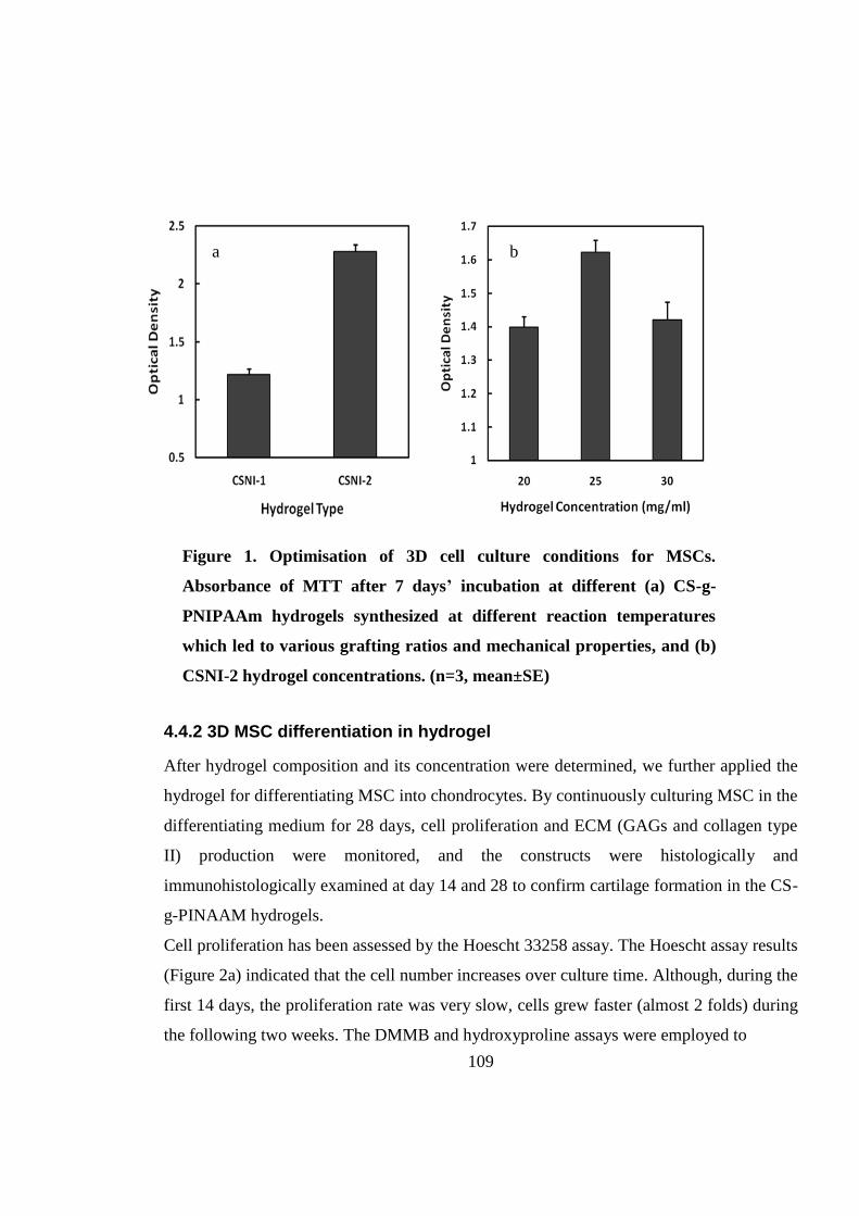
109
a b
4.4.2 3D MSC differentiation in hydrogel
After hydrogel composition and its concentration were determined, we further applied the
hydrogel for differentiating MSC into chondrocytes. By continuously culturing MSC in the
differentiating medium for 28 days, cell proliferation and ECM (GAGs and collagen type
II) production were monitored, and the constructs were histologically and
immunohistologically examined at day 14 and 28 to confirm cartilage formation in the CS-
g-PINAAM hydrogels.
Cell proliferation has been assessed by the Hoescht 33258 assay. The Hoescht assay results
(Figure 2a) indicated that the cell number increases over culture time. Although, during the
first 14 days, the proliferation rate was very slow, cells grew faster (almost 2 folds) during
the following two weeks. The DMMB and hydroxyproline assays were employed to
Figure 1. Optimisation of 3D cell culture conditions for MSCs.
Absorbance of MTT after 7 days’ incubation at different (a) CS-g-
PNIPAAm hydrogels synthesized at different reaction temperatures
which led to various grafting ratios and mechanical properties, and (b)
CSNI-2 hydrogel concentrations. (n=3, mean±SE)

110
*
*
* a
*
*
*
*
* b
*
*
* c
quantify GAGs and collagen deposition, respectively. The GAG level (Figure 2b)
increased significantly from 0.8 µg/mg dry gel at day 7 to 4.8 µg/mg dry gel at day 28.
Total collagen accumulation (Figure 2c) showed 7 fold increments during 28 days. GAGs
and collagens are the main components of cartilagous tissues. Enhanced GAG and collagen
Figure 2. Quantification of (a) DNA, (b) GAG and (c) total collagen in cell-seeded
CSNI-2 over 4 weeks. All values were normalized by the dry weight of the hydrogel
(n=3, mean ± SE). * P˂ 0.05, ** P˂ 0.01

111
deposition revealed the successful chondrogenic differentiation of MSCs within the 3D
microenvironment provided by CS-g-PNIPAAm. The ECM deposition rate was equivalent
to or higher than those of other biomaterials which have been used for cartilage tissue
engineering (60-63). These results suggest that CS-g-PNIPAAm is a promising hydrogel
for this application.
We further confirmed the cartilage tissue formation by histological and
immunohistochemical staining of constructs as shown in Figure 3. Figures 3a & b show
low (4X) and high (10X) magnification micrographs of H&E staining. The black spots
represent cells and all other components including ECM and hydrogel are stained red. This
images revealed that cells were well distributed inside the structure while preserving their
round morphology in the bulk hydrogel. The hydrogel surrounding the cells provided a 3D
microenvironment so that the cells present in a round shape, which is very similar to the
cell morphology in the middle zone of the cartilage. Figures 3c & d represent safranin O-
stained sections where the presence of GAGs within ECM can be distinguished by pink
colour. The intensity of positively stained pericellular regions was increased from day 14
(Figure 3c) to day 28 (Figure 3d). It confirmed continuous GAG secretion by cells and
formation of sulfated proteoglycan-rich ECM which is seen in native articular cartilage
tissues. Figures 3e & f show the distribution of collagen type II, a cartilage-specific ECM
component, by immunohistochemical staining. Positive collagen type II was stained in
brown color. The darker stained regions around the cells at day 28 (Figure 3f) than day 14
(Figure 3e) further supported the sustained collagen type II production over time as a
specific marker of chondrogenesis.
Histological and immunohistochemical staining qualitatively verified the chondrogenic
differentiation of MSCs encapsulated within CS-g-PNIPAAm hydrogels. The level of
ECM deposition was visually identical to other comparable popular hydrogels such as
agarose and gelatin loaded with MSCs, after 90 days of culture in chondrogenic medium
(60).

112
a b
c d
f g
Figure 3. Histological and immunohistochemical staining of the cell-
seeded hydrogels. (a-b) Sections were stained with H&E at day 14 (a)
and day 28 (b); (c-d) sections were stained with Safranin O for GAGs
after 14 days (c) and 28 days (d) of incubation; and (f-g) sections were
immunohistochemically stained for collagen type II after 14 days (f) and
28 days (g) of incubation. (scale bar (a) =200 μm, 4× magnification; (b-g)
= 50 μm, 10×)

113
4.4.3 3D cell-laden microconstructs: Preparation, cell organization and
chondrogenesis
After the CS-g-PNIPAAm hydrogel has been demonstrated to be able to support cell
proliferation and differentiation, we then applied cell-laden thermoresponsive hydrogel
into the microengineered constructures for engineering/mimicing formation of different
zones of cartilages by precise control of fabrication parameters of microconstructures.
Scheme 1b illustrates the fabrication process of microengineered cell-laden
thermoresponsive CS-g-PNIPAAm hydrogel patterns using microscale anisotropic PEG-
DMA grooves as a micromold. Figure 4a presents a photograph of a micropatterned PEG-
DMA on a TMSPMA glass slide. The overall dimension of the device was 1.5 cm (H) ×
1.4 cm (W). Figures 4b-d show different microfabricated PEG-DMA patterns with the
same channel dpeth (150 µm) but 3 different channel widths (50, 100 and 150 µm) at the
same spacing between microchannels (200 µm). From these micrographs, channel sizes
weree in precise agreement with their nominal dimension and all grooves on each
patterned surafce were identical. To ensure that CS-g-PNIPAAm hydrogel was well
located within the PEG-DMA microchannels, different fluorescence beads were used to
distinguish the PEG-DMA and CS-g-PNIPAAm hydrogel. PEG-DMA was mixed with red
fluorescent beads before lithography, while CS-g-PNIPAAm solution was mixed with
green fluorescent beads, deposited into the channels and gelled at 37˚C. The construct was
visualized under a fluorescence microscope equipped with a temperature control chamber.
Figure 4e demonstrates that CS-g-PNIPAAm was adequately patterned within the PEG
microgrooves.
After the cells has been successfully encapsulated in the hydrogel and solidified within the
microgrooves, the cells were continuously incubated for 5 days. Cell-laden
microconstructs were stained with calcein AM and EthD-1 to verify cellular viability and
proliferation. At day 1 (Figure 5a), viable cells were individually distributed in a round
morphology within micropatterned hydrogel. Cells exhibited an interconnected network
with neighboring cells at a longer culture time (Figure 5b). A higher green intensity at day
5 in comparison to day 1 denoted an increase in cell number, demonstrating cells have

114
proliferated inside the hydrogel in the microgrooves. The majority of cells remained viable
and biologically active while a few dead cells (stained in red) can be found at day 1 and
day 5.
The microconstructs were also stained with phalloidin and DAPI to visualize filamentous
F-actin of the cytoskeleton and cell nuclei, respectively. Figure S1 displays a low
Figure 4. Images of micromolds and fabrication of micropatterned hydrogels. (a)
Overview of a PEG-DMA micromold, with the dimensions of 1.4 cm × 1.5 cm. (b-d)
Representative phase contrast images of PEG-DMA micromolds fabricated in
different channel sizes: (b) 50 µm, (c) 100 µm, (d) 150 µm. Yellow arrows show the
channel width. (scale bars: 200 µm, 10× magnification). (e) Fluorescent microscopic
image of micropatterned hydrogel without cells. Green and red fluorescent beads
were embedded in CS-g-PNIPAAm and PEG-DMA gels, respectively before gelation
(scale bar = 100 µm).
1.4
cm
1.5
cm
a b c
d e

115
Figure 5. Live/dead cell staining of
cell-laden micropatterned hydrogel
(50 µm) after (a) 1 day and (b) 5
days’ incubation. Green colour
indicates live cells and red spots
represent dead cells. (scale bars=
200 µm, 4×)
Figure S1. Representative low
magnification (4X) F-actin/DAPI
stained microconstruct (50 µm
microchannel width) at day 5 of
incubation. (scale bar = 200 µm)
a
b
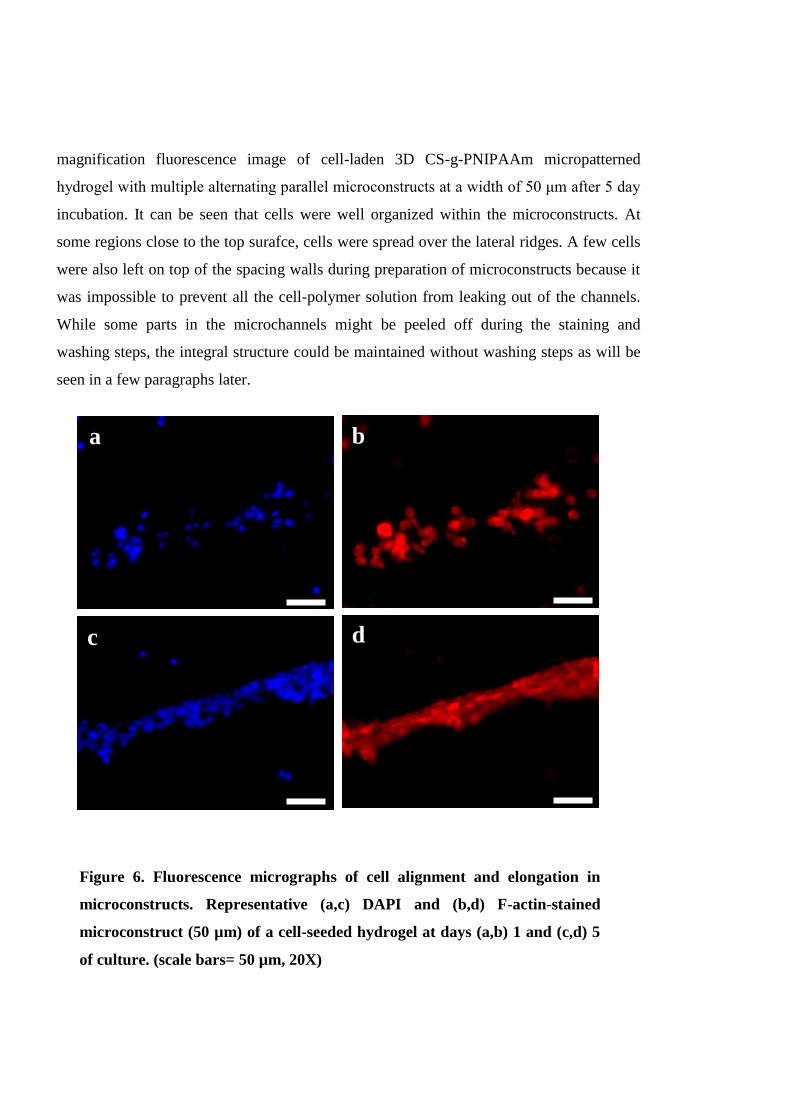
116
c d
a b
d
magnification fluorescence image of cell-laden 3D CS-g-PNIPAAm micropatterned
hydrogel with multiple alternating parallel microconstructs at a width of 50 μm after 5 day
incubation. It can be seen that cells were well organized within the microconstructs. At
some regions close to the top surafce, cells were spread over the lateral ridges. A few cells
were also left on top of the spacing walls during preparation of microconstructs because it
was impossible to prevent all the cell-polymer solution from leaking out of the channels.
While some parts in the microchannels might be peeled off during the staining and
washing steps, the integral structure could be maintained without washing steps as will be
seen in a few paragraphs later.
Figure 6. Fluorescence micrographs of cell alignment and elongation in
microconstructs. Representative (a,c) DAPI and (b,d) F-actin-stained
microconstruct (50 µm) of a cell-seeded hydrogel at days (a,b) 1 and (c,d) 5
of culture. (scale bars= 50 µm, 20X)
117
The cellular nucleus images at day 1 and day 5 are presented in Figures 6a & c,
respectively. It can be seen that the individual cell nuclei were scattered in the hydrogel at
day 1 in a round shape (Figure 6a). More cell nuclei could be found at day 5 in a stretched
shape (Figure 6c). This confirmed that cells proliferate inside the hydrogel within the
grooves. Cells have also been oriented along the horizonal axis of the microchannels. The
cellular cytoskeleton was also stretched along the main horizontal axis of the microgrooves
at day 5 (Figure 6d) in comparison to a round shape at day 1 (Figure 6b), which
demonstrateed that cells have been re-oriented in the hydrogel. Long stressed fibers were
found to run in parallel according to the orientation of the cells. Cells have been reported to
induce the generation of stressed fibers when cells are exposed to their surrounding
materials with a high mechanical property (64). Our results are in agreement with previous
studies that cells could be aligned and elongated when cultured on the surface of
microgrooves (65-67) or encapsulated in patterned microconstructs (54, 68).
Cell alignment was further quantified by the nuclear alignment angle which is defined as
the orientation of the major axis of the nuclear shape by fitting in the best ellipse with
respect to the horizontal axis of the microgrooves. Figures 7a-d represent the histogram of
cell nuclear orientation in 10˚ increments within typical unpatterned and patterned
microconstructs with a width of 150, 100 and 50 μm at day 5, respectively. The
corresponding phalloidin and DAPI staining micrographs are also inserted as an internal
panel in the histograms. The unpatterned histogram (Figure 7a) shows that cell nuclei were
randomly oriented in various directions. However, cell nuclei were stretched to some
extent. This again confirmed that cells have been responsive to the supporting
microenvironment with a high mechanical storage moduli. Histograms of 150, 100, 50 μm
wide microconstructs (Figure 7b-d) revealed that more cells intend to have small nuclear
angels with respect to the channel longitude axis by reducing the channel sizes, suggesting
higher alignment at a smaller channel width. Figure 7e summarizes the percentage of the
aligned cells in unpatterned and patterned gels with different widths. Cells were considered
to be aligned when their nuclear angles were less than 20˚ with respect to the microchannel
longitude axis represented by mean cell nuclear angles (53). Figure 7e demonstrates that
cells became more aligned over time in all patterned microconstructs, while there was no

118
e
d
b
c
a
f
Figure 7. Quantification of cell alignment and elongation as a function of
microconstruct width and incubation time. (a-d) Representative histograms of
relative alignment in 10° increments on day 5 of culture in unpatterned and 150,
100 and 50 µm microchannel widths, respectively. Embedded images represent
high magnification (20X) F-actin/DAPI stained microconstructs (scale bars (a-d)
= 50 µm). (e) Mean percentage of aligned cell nuclei (within 20° of preferred
nuclear orientation) in unpatterend and patterned gels at days 1 and 5. (f) Mean
nuclear shape indices (spect ratio) of unpatterned and patterned microconstructs
at days 1 and 5. (n=3, mean±SD, *P˂ 0.05, **P˂ 0.01, ***P˂ 0.001)
119
significant changes in cell alignment in unpatterned constructs. The most significant
increment over time was found in 100 μm microconstructs (from 25±1% at day 1 to
74±3% at day 5). At day 1, cells in 50 μm microgrooves were more aligned (45±12%) in
comparison with two other widths, while no significant difference could be seen between
unpatterned, 150 and 100 μm micropatterns. At day 5, cells in 50 and 100 μm
microconstructs (75±6% and 74±3%, respectively) were more aligned than those in 150
μm (43±3%). A significant increase has been found for the percentage of cell alignment in
all widths at day 5 in comparison with day 1. The significant increase was also applied to
patterned structure when compared to the unpatterend constructs at day 5. Interestingly, a
similar percentage of aligned cells were found for 100 and 50 μm micropatterns at day 5.
Jadin et. al. quantified the chondrocyte organization by their angles to the nearest
neighboring cell. They found that neighboring cells were arranged horizontally in the
superficial zone with an averaged angle of 20° and vertically in the deep zone with an
angle of 60°. In other regions of the cartilage, the angle was 32°, indicative of an isotropic
organization (69). Our experiments suggested that cells incubating within 50-100 μm
microgooves were aligned in the pattern similar to the superficial zone and in gaps at 150
μm or wider were more likely to form the middle zone.
Cell elongation was quantitatively studied by estimating the cell nuclear shape index. The
aspect ratio, the ratio of the major to the minor axis of the best fit ellipse from individual
cell nucleus, was empolyed as the shape index. Figure 7f summarizes the results of cell
shape indices in the unpatterned and patterned microconstructs with a width of 150, 100
and 50 μm at day 1 and day 5. At day 1, there was no significant difference between the
shape indices of the nuclei in different groups including unpatterned and patterned
hydrogels. The aspect ratio was close to 1 for all groups suggesting an almost round shape
of cell nuclei. The shape index did not change at day 5 in unpatterned gels (1.202±0.07) in
comparison with day 1 (1.239±0.06). In contrast, within all patterned groups, the nuclear
aspect ratios at day 5 were greater than those of the same group at day 1 (P˂ 0.01). The
change became more significant by decreasing the microconstruct width. At day 5, the
shape indices were significantly different (P˂ 0.05) between the unpatterned and patterned
groups. The highest aspect ratio of 2.075±0.161 was found for cells in the 50 μm

120
micropatterns. These results suggest that cells became more elongated in the more narrow
microgroovers and the extent of elongation can be adjusted by controlling the widths of the
microgrooves.
The cell-laden microconstructs were further incubated in the chondrogenic medium for 21
days and visualized under a multiphoton microscope. Some cellular components and
biomaterials are detectable under the multiphoton microscope due to their autofluorescent
(AF) properties; and these include some cell contents such as NADH coenzymes (70), and
cell derbis (71) as well as some biomaterials used as scaffolds in tissue engineering (72,
73) including chitosan (74). Collagen in ECM can also be distinguishable from their SHG
signals. Collagen is the strong source of second harmonics in animal tissues due to its
unusual noncentrosymmetric structure and high degree of crystallinity (75). An integrated
architecture of AF signal (red) (Figure 8a) confirmed that the structure of microconstructs
was well preserved after 21 day incubation. As the multiphoton microscope can detect
a b
Figure 8. Multiphoton microscopy image of micropatterned cell-laden
hydrogel after 21 days’ incubation. (a) Autofluorescence (AF) of cell-laden
CS-g-PNIPAAm gel. (b) Overlay of AF (red) and second harmonic
generation signals (green), indicating collagens in extracellular matrix.
White arrows indicate combined collagens from different cells. (scale bars
= 100 µm, 10× magnification).
121
autoflorescence signals, microconstructs did not need any staining and hence, washing
steps and solution changes were avoided before imaging. As mentioned before, these
preparation steps might bring partial damage to the microconstructs as shown in previous
staining assays. SHG signals of collagen (green) are observed in Figure 8b. The detectable
collagen signals denoted that MSCs have become differentiated or partially differentiated
cells (74). Collagen was presented as a round shape, surrounding the individual cells. At
some regions indicated by white arrows collagen was aligned along the horizonal axis. The
reason for the scattered collagen distribution might be due to the low cell density. As
described earlier in DNA quantification (Figure 2a), the cell number did not increase up to
day 14, and the cells started to proliferate after 14 days. It is expected that after culturing in
the chondrogenic medium for a longer time, collagen will be integrated and aligned.
Images of safranin O histologically and collagen II immunohistologically stained
microconstructs (cultured in the chondrogenic medium for 2 weeks) are presented in
Figure S2. Although it was difficult to visualize the positive stains due to the high
thickness of the microconstructs under the phase contrast microscopy, positive stains could
be seen at the edges and broken regions of the gel (Figure S2a). Collagen type II-positive
components were not distinguishable by immunostaining within the micropatterns due to
the dark background of the thick gel (Figure S2b). However, The darker stained spots
could be cells being stained.
The chondrocyte spatial arrangement is vital in the functionality of the mature articular
cartilage. It is an essential requirement for homeostasis (76). In addition, the spatial
cellular organisation regulates cells through direct cell–cell contact and paracrine or
autocrine factors. Cellular organization has also a great impact on the local solid and fluid
environment in which the cells reside, when the cells are exposed to external mechanical or
chemical stimuli (69). Moreover, the actin cytoskeleton and cell shape play a role in
determining the zone-specific characteristics (77). To create an artificial microenvironment
for allowing spatial cellular organisation and maintaining cell shape in each zone is an
important step for successful cartilage tissue engineering. Among three zones, the
superficial zone is the most imporant for cartilages. It has been recently shown that
superficial zone chondrocytes modulate the surface mechanical properties of engineered

122
a
b
Figure S2. Histological and
immunohistochemical staining of the
cell-seeded patterned (100 µm channel
width) hydrogels. Samples were
stained (a) with Safranin O for GAGs,
and (b) immunohistochemically for
collagen type II after 21 days
incubation. White arrows point out the
positive GAG stained spots. (scale bars
= 50 μm, 10×)
cartilage tissue (77). The flattened geometry of chondrocytes encourages the superficial
zone phenotype (78). The changes in cellular arrangement at the superficial zone of the
articular cartilage arose at the onset of osteoarthritis (79). Micropatterning was employed
in this study to form the superficial zone and middle zone with the thermoresponsive
hydrogels. The cellular alignment and elongation in the narrow microgrooves (50-100 μm)
after culturing cells in the hydrogels for several days could mimic the superficial zonal
structure, while cells in a wide microgroove (above 150 μm) or in bulk hydrogel could

123
form an isotropic structure in the middle zone of the cartilage. While these initial results
are very promising for regenerating layered cartilage, recreating an integrated macroscale
tissue by stacking the microconstructs remains to be addressed in our future research.
4.5 Conclusions
Mesenchymal stem cells incorporated in chitosan-g-PNIPAAm as a thermoresponsive
hydrogel proliferated fast in the copolymer with a mechanically strong structure. By
incubating MSCs in the thermoresponsive hydrogel in the chondrogenic medium for over
28 days, cartilaginous tissue formation was confirmed by biochemical, histochemical and
immunohistochemical assays. The cell-laden thermoresponsive hydrogel was further
micropatterned using PEG-DMA stamps by simply incubation at 37 °C without UV
radiation and photoinitiators. Cells were aligned and elongated in the narrow microchannel
gaps, suggesting that the microfabrication method can be exploited for 3D cell orientation
and elongation to mimic the cell shape and organization in the superficial zone of native
cartilages. However, cells in the wide microchannel as unpatterned microstructures served
to resemble the middle zone of articular cartilage. Our results suggest that micropatterning
of 3D cell-laden CS-g-PNIPAAm hydrogel is a promising method for bi-zonal cartilage
tissue engineering.
124
4.6 References
1. Mansour JM. Biomechanics of cartilage. Kinesiology: the mechanics and
pathomechanics of human movement. 2003:66-79.
2. Newman AP. Articular cartilage repair. The American journal of sports medicine.
1998;26(2):309-24.
3. Temenoff JS, Mikos AG. Review: tissue engineering for regeneration of articular
cartilage. Biomaterials. 2000;21(5):431-40.
4. Hunziker EB, Quinn TM, Häuselmann HJ. Quantitative structural organization of
normal adult human articular cartilage. Osteoarthritis and Cartilage. 2002;10(7):564-72.
5. Poole AR, Kojima T, Yasuda T, Mwale F, Kobayashi M, Laverty S. Composition
and structure of articular cartilage: a template for tissue repair. Clinical orthopaedics and
related research. 2001;391:S26-S33.
6. Wise JK, Yarin AL, Megaridis CM, Cho M. Chondrogenic differentiation of
human mesenchymal stem cells on oriented nanofibrous scaffolds: engineering the
superficial zone of articular cartilage. Tissue Engineering Part A. 2008;15(4):913-21.
7. Keeney M, Lai JH, Yang F. Recent progress in cartilage tissue engineering. Current
opinion in biotechnology. 2011;22(5):734-40.
8. Hunziker EB. Articular cartilage repair: basic science and clinical progress. A
review of the current status and prospects. Osteoarthritis and Cartilage. 2002;10(6):432-63.
9. Johnstone B, Alini M, Cucchiarini M, Dodge GR, Eglin D, Guilak F, et al. Tissue
engineering for articular cartilage repair--the state of the art. Eur Cell Mater. 2013;25:248-
67.
10. Lanza R, Longer R, Vacanti J, editors. Principles of Tissue Engineering. 3 ed:
Elsevier Academic Press; 2007.
11. Coates EE, Fisher JP. Engineering Superficial Zone Chondrocytes from
Mesenchymal Stem Cells. Tissue Engineering Part C: Methods. 2014.
12. Spiller KL, Maher SA, Lowman AM. Hydrogels for the repair of articular cartilage
defects. Tissue Engineering Part B: Reviews. 2011;17(4):281-99.

125
13. Fedorovich NE, Alblas J, Wijin JR, Hennink WE, Verbout AJ, Dhert WJA.
Hydrogels as Extracellular Matrices for Skeletal Tissue Engineering: State-of-the-Art and
Novel Application in Organ Printing. TISSUE ENGINEERING. 2007;13(8):1905-25.
14. Kim I-Y, Seo S-J, Moon H-S, Yoo M-K, Park I-Y, Kim B-C, et al. Chitosan and its
derivatives for tissue engineering applications. Biotechnology Advances. 2008;26(1):1-21.
15. Di Martino A, Sittinger M, Risbud MV. Chitosan: A versatile biopolymer for
orthopaedic tissue engineering. Biomaterials. 2005;26(30):5983-90.
16. Francis Suh JK, Matthew HWT. Application of chitosan-based polysaccharide
biomaterials in cartilage tissue engineering: a review. Biomaterials. 2000;21(24):2589-98.
17. McCullen SD, Autefage H, Callanan A, Gentleman E, Stevens MM. Anisotropic
fibrous scaffolds for articular cartilage regeneration. Tissue Engineering Part A.
2012;18(19-20):2073-83.
18. Klein T, Schumacher B, Schmidt T, Li K, Voegtline M, Masuda K, et al. Tissue
engineering of stratified articular cartilage from chondrocyte subpopulations. Osteoarthritis
and Cartilage. 2003;11(8):595-602.
19. Sharma B, Williams CG, Kim TK, Sun D, Malik A, Khan M, et al. Designing zonal
organization into tissue-engineered cartilage. Tissue engineering. 2007;13(2):405-14.
20. Kim T-K, Sharma B, Williams C, Ruffner M, Malik A, McFarland E, et al.
Experimental model for cartilage tissue engineering to regenerate the zonal organization of
articular cartilage. Osteoarthritis and Cartilage. 2003;11(9):653-64.
21. Bhumiratana S, Eton RE, Oungoulian SR, Wan LQ, Ateshian GA, Vunjak-
Novakovic G. Large, stratified, and mechanically functional human cartilage grown in
vitro by mesenchymal condensation. Proceedings of the National Academy of Sciences.
2014;111(19):6940-5.
22. Sharma B, Elisseeff JH. Engineering structurally organized cartilage and bone
tissues. Annals of biomedical engineering. 2004;32(1):148-59.
23. Nguyen LH, Kudva AK, Saxena NS, Roy K. Engineering articular cartilage with
spatially-varying matrix composition and mechanical properties from a single stem cell
population using a multi-layered hydrogel. Biomaterials. 2011;32(29):6946-52.
126
24. Klein TJ, Rizzi SC, Schrobback K, Reichert JC, Jeon JE, Crawford RW, et al.
Long-term effects of hydrogel properties on human chondrocyte behavior. Soft matter.
2010;6(20):5175-83.
25. Walker KJ, Madihally SV. Anisotropic temperature sensitive chitosan‐based
injectable hydrogels mimicking cartilage matrix. Journal of Biomedical Materials Research
Part B: Applied Biomaterials. 2014.
26. Lee CS, Gleghorn JP, Won Choi N, Cabodi M, Stroock AD, Bonassar LJ.
Integration of layered chondrocyte-seeded alginate hydrogel scaffolds. Biomaterials.
2007;28(19):2987-93.
27. Ng KW, Wang CCB, Mauck RL, Kelly TAN, Chahine NO, Costa KD, et al. A
layered agarose approach to fabricate depth‐dependent inhomogeneity in
chondrocyte‐seeded constructs. Journal of Orthopaedic Research. 2005;23(1):134-41.
28. Bryant SJ, Anseth KS. Controlling the spatial distribution of ECM components in
degradable PEG hydrogels for tissue engineering cartilage. Journal of Biomedical
Materials Research Part A. 2003;64(1):70-9.
29. Woodfield T, Blitterswijk CV, Wijn JD, Sims T, Hollander A, Riesle J. Polymer
scaffolds fabricated with pore-size gradients as a model for studying the zonal organization
within tissue-engineered cartilage constructs. Tissue engineering. 2005;11(9-10):1297-311.
30. Erisken C, Kalyon DM, Wang H. Functionally graded electrospun
polycaprolactone and β-tricalcium phosphate nanocomposites for tissue engineering
applications. Biomaterials. 2008;29(30):4065-73.
31. Steele J, McCullen S, Callanan A, Autefage H, Accardi M, Dini D, et al.
Combinatorial scaffold morphologies for zonal articular cartilage engineering. Acta
biomaterialia. 2014;10(5):2065-75.
32. Marsano A, Wendt D, Quinn T, Sims T, Farhadi J, Jakob M, et al. Bi-zonal
cartilaginous tissues engineered in a rotary cell culture system. Biorheology.
2006;43(3):553-60.

127
33. Spitters TW, Leijten JC, Deus FD, Costa IB, van Apeldoorn AA, van Blitterswijk
CA, et al. A dual flow bioreactor with controlled mechanical stimulation for cartilage
tissue engineering. Tissue Engineering Part C: Methods. 2013;19(10):774-83.
34. Kock LM, Ito K, van Donkelaar CC. Sliding indentation enhances collagen content
and depth-dependent matrix distribution in tissue-engineered cartilage constructs. Tissue
Engineering Part A. 2013;19(17-18):1949-59.
35. Chen T, Hilton MJ, Brown EB, Zuscik MJ, Awad HA. Engineering superficial
zone features in tissue engineered cartilage. Biotechnology and bioengineering.
2013;110(5):1476-86.
36. Schrobback K, Malda J, Crawford RW, Upton Z, Leavesley DI, Klein TJ. Effects
of oxygen on zonal marker expression in human articular chondrocytes. Tissue
Engineering Part A. 2012;18(9-10):920-33.
37. Spitters TW, Mota CM, Uzoechi SC, Slowinska B, Martens D, Moroni L, et al.
Glucose gradients influence zonal matrix deposition in 3D cartilage constructs. Tissue
engineering. 2014(ja).
38. Thorpe SD, Nagel T, Carroll SF, Kelly DJ. Modulating gradients in regulatory
signals within mesenchymal stem cell seeded hydrogels: a novel strategy to engineer zonal
articular cartilage. PloS one. 2013;8(4):e60764.
39. Hwang NS, Varghese S, Lee HJ, Theprungsirikul P, Canver A, Sharma B, et al.
Response of zonal chondrocytes to extracellular matrix-hydrogels. FEBS letters.
2007;581(22):4172-8.
40. Nichol JW, Koshy ST, Bae H, Hwang CM, Yamanlar S, Khademhosseini A. Cell-
laden microengineered gelatin methacrylate hydrogels. Biomaterials. 2010;31(21):5536-
44.
41. Schuurman W, Gawlitta D, Klein TJ, ten Hoope W, van Rijen MH, Dhert WJ, et al.
Zonal chondrocyte subpopulations reacquire zone-specific characteristics during in vitro
redifferentiation. The American journal of sports medicine. 2009;37(1 suppl):97S-104S.
42. Albrecht DR, Tsang VL, Sah RL, Bhatia SN. Photo-and electropatterning of
hydrogel-encapsulated living cell arrays. Lab on a Chip. 2005;5(1):111-8.

128
43. Liu VA, Bhatia SN. Three-dimensional photopatterning of hydrogels containing
living cells. Biomedical microdevices. 2002;4(4):257-66.
44. Yamato M, Konno C, Utsumi M, Kikuchi A, Okano T. Thermally responsive
polymer-grafted surfaces facilitate patterned cell seeding and co-culture. Biomaterials.
2002;23(2):561-7.
45. Tsuda Y, Kikuchi A, Yamato M, Nakao A, Sakurai Y, Umezu M, et al. The use of
patterned dual thermoresponsive surfaces for the collective recovery as co-cultured cell
sheets. Biomaterials. 2005;26(14):1885-93.
46. Jun I, Kim SJ, Lee JH, Lee YJ, Shin YM, Choi E, et al. Transfer Printing of Cell
Layers with an Anisotropic Extracellular Matrix Assembly using Cell‐Interactive and
Thermoresponsive Hydrogels. Advanced Functional Materials. 2012;22(19):4060-9.
47. Tekin H, Anaya M, Brigham MD, Nauman C, Langer R, Khademhosseini A.
Stimuli-responsive microwells for formation and retrieval of cell aggregates. Lab on a
Chip. [10.1039/C004732E]. 2010;10(18):2411-8.
48. Tekin H, Tsinman T, Sanchez JG, Jones BJ, Camci-Unal G, Nichol JW, et al.
Responsive Micromolds for Sequential Patterning of Hydrogel Microstructures. Journal of
the American Chemical Society. 2011 2011/08/24;133(33):12944-7.
49. Mellati A, Dai S, Bi J, Jin B, Zhang H. A Biodegradable Thermoresponsive
Hydrogel with Tuneable Properties for Mimicking Three-Dimensional Microenvironments
of Stem Cells. RSC Advances. 2014.
50. Hwang NS, Varghese S, Elisseeff J. Cartilage tissue engineering. Stem Cell
Assays: Springer; 2007. p. 351-73.
51. Hoemann CD. Molecular and biochemical assays of cartilage components.
Cartilage and osteoarthritis: Springer; 2004. p. 127-56.
52. Chung R, Cool JC, Scherer MA, Foster BK, Xian CJ. Roles of neutrophil-mediated
inflammatory response in the bony repair of injured growth plate cartilage in young rats.
Journal of Leukocyte Biology. 2006 December 1, 2006;80(6):1272-80.

129
53. Annabi N, Tsang K, Mithieux SM, Nikkhah M, Ameri A, Khademhosseini A, et al.
Highly elastic micropatterned hydrogel for engineering functional cardiac tissue.
Advanced functional materials. 2013;23(39):4950-9.
54. Aubin H, Nichol JW, Hutson CB, Bae H, Sieminski AL, Cropek DM, et al.
Directed 3D cell alignment and elongation in microengineered hydrogels. Biomaterials.
2010;31(27):6941-51.
55. Lutolf MP, Hubbell JA. Synthetic biomaterials as instructive extracellular
microenvironments for morphogenesis in tissue engineering. Nat Biotech. 2005;23(1):47-
55.
56. Guilak F, Cohen DM, Estes BT, Gimble JM, Liedtke W, Chen CS. Control of Stem
Cell Fate by Physical Interactions with the Extracellular Matrix. Cell Stem Cell.
2009;5(1):17-26.
57. Kim M, Lee JY, Jones CN, Revzin A, Tae G. Heparin-based hydrogel as a matrix
for encapsulation and cultivation of primary hepatocytes. Biomaterials. 2010;31(13):3596-
603.
58. Bae H, Ahari AF, Shin H, Nichol JW, Hutson CB, Masaeli M, et al. Cell-laden
microengineered pullulan methacrylate hydrogels promote cell proliferation and 3D cluster
formation. Soft matter. 2011;7(5):1903-11.
59. Dillon GP, Xiaojun Y, Sridharan A, Ranieri JP, Bellamkonda RV. The influence of
physical structure and charge on neurite extension in a 3D hydrogel scaffold. Journal of
Biomaterials Science, Polymer Edition. 1998 ;9(10):1049-69.
60. Lin H, Cheng AW-M, Alexander PG, Beck AM, Tuan RS. Cartilage Tissue
Engineering Application of Injectable Gelatin Hydrogel with In Situ Visible-Light-
Activated Gelation Capability in both Air and Aqueous Solution. Tissue Engineering Part
A. 2014.
61. Dai W, Kawazoe N, Lin X, Dong J, Chen G. The influence of structural design of
PLGA/collagen hybrid scaffolds in cartilage tissue engineering. Biomaterials.
2010;31(8):2141-52.

130
62. Jin R, Moreira Teixeira L, Dijkstra P, van Blitterswijk C, Karperien M, Feijen J.
Enzymatically-crosslinked injectable hydrogels based on biomimetic dextran–hyaluronic
acid conjugates for cartilage tissue engineering. Biomaterials. 2010;31(11):3103-13.
63. DeKosky BJ, Dormer NH, Ingavle GC, Roatch CH, Lomakin J, Detamore MS, et
al. Hierarchically designed agarose and poly (ethylene glycol) interpenetrating network
hydrogels for cartilage tissue engineering. Tissue Engineering Part C: Methods.
2010;16(6):1533-42.
64. Walboomers X, Ginsel L, Jansen J. Early spreading events of fibroblasts on
microgrooved substrates. Journal of biomedical materials research. 2000;51(3):529-34.
65. Hosseini V, Ahadian S, Ostrovidov S, Camci-Unal G, Chen S, Kaji H, et al.
Engineered contractile skeletal muscle tissue on a microgrooved methacrylated gelatin
substrate. Tissue Engineering Part A. 2012;18(23-24):2453-65.
66. Thompson DM, Buettner HM. Schwann cell response to micropatterned laminin
surfaces. Tissue engineering. 2001;7(3):247-65.
67. Charest JL, García AJ, King WP. Myoblast alignment and differentiation on cell
culture substrates with microscale topography and model chemistries. Biomaterials.
2007;28(13):2202-10.
68. Nikkhah M, Eshak N, Zorlutuna P, Annabi N, Castello M, Kim K, et al. Directed
endothelial cell morphogenesis in micropatterned gelatin methacrylate hydrogels.
Biomaterials. 2012;33(35):9009-18.
69. Jadin KD, Bae WC, Schumacher BL, Sah RL. Three-dimensional (3-D) imaging of
chondrocytes in articular cartilage: Growth-associated changes in cell organization.
Biomaterials. 2007;28(2):230-9.
70. Schenke-Layland K, Riemann I, Damour O, Stock UA, König K. Two-photon
microscopes and in vivo multiphoton tomographs—Powerful diagnostic tools for tissue
engineering and drug delivery. Advanced drug delivery reviews. 2006;58(7):878-96.
71. Schenke-Layland K, Vasilevski O, Opitz F, König K, Riemann I, Halbhuber K, et
al. Impact of decellularization of xenogeneic tissue on extracellular matrix integrity for
tissue engineering of heart valves. Journal of structural biology. 2003;143(3):201-8.

131
72. Lee H-S, Teng S-W, Chen H-C, Lo W, Sun Y, Lin T-Y, et al. Imaging human bone
marrow stem cell morphogenesis in polyglycolic acid scaffold by multiphoton microscopy.
Tissue engineering. 2006;12(10):2835-41.
73. Heydarkhan-Hagvall S, Schenke-Layland K, Dhanasopon AP, Rofail F, Smith H,
Wu BM, et al. Three-dimensional electrospun ECM-based hybrid scaffolds for
cardiovascular tissue engineering. Biomaterials. 2008;29(19):2907-14.
74. Chen W-L, Huang C-H, Chiou L-L, Chen T-H, Huang Y-Y, Jiang C-C, et al.
Multiphoton imaging and quantitative analysis of collagen production by chondrogenic
human mesenchymal stem cells cultured in chitosan scaffold. Tissue Engineering Part C:
Methods. 2010;16(5):913-20.
75. Cox G, Kable E. Second-harmonic imaging of collagen. Cell Imaging Techniques:
Springer; 2006. p. 15-35.
76. Jadin KD, Wong BL, Bae WC, Li KW, Williamson AK, Schumacher BL, et al.
Depth-varying density and organization of chondrocytes in immature and mature bovine
articular cartilage assessed by 3D imaging and analysis. Journal of Histochemistry &
Cytochemistry. 2005;53(9):1109-19.
77. Peng G, McNary SM, Athanasiou KA, Reddi AH. Surface Zone Articular
Chondrocytes Modulate the Bulk and Surface Mechanical Properties of the Tissue-
Engineered Cartilage. Tissue Engineering Part A. 2014.
78. McNary SM, Athanasiou KA, Reddi AH. Transforming Growth Factor β-Induced
Superficial Zone Protein Accumulation in the Surface Zone of Articular Cartilage Is
Dependent on the Cytoskeleton. Tissue Engineering Part A. 2014;20(5-6):921-9.
79. Becerra J, Andrades JA, Guerado E, Zamora-Navas P, López-Puertas JM, Reddi
AH. Articular cartilage: structure and regeneration. Tissue Engineering Part B: Reviews.
2010;16(6):617-27.

132

133
CHAPTER FIVE
Influence of Polymer Molecular Weight on the 5.
Cytotoxicity of Poly (N-isopropylacrylamide)

134

135
Influence of polymer molecular weight on the cytotoxicity of
poly (N-isopropylacrylamide)
Amir Mellati, Meisam Valizadeh Kiamahalleh, Sheng Dai, Jingxiu Bi, Bo Jin, Hu Zhang*
School of Chemical Engineering, the University of Adelaide, Adelaide SA5005, Australia
*Corresponding author
E-mail: [email protected]
Tel: + 61 8 8313 3810
Colloid and Interface Science Communications. (Submitted, Reference number:
COLCOM-D-14-00131)

136
5.1 Abstract
Poly (N-isopropylacrylamide) (PNIPAAm) has been extensively used as a
thermoresponsive material in various biomedical applications. In this study, we
synthesized a series of PNIPAAms with well-defined molecular weights and examined
polymer molecular weight-dependent cytotoxicity. Results indicated that low molecular
weight PNIPAAm (degree of polymerization (DP) = 35) is inherently toxic to cells, and
necrosis is the dominant cell death mechanism. Moderate-sized PNIPAAms with their DP
between 100 and 200 are non-cytotoxic. For the PNIPAAm with a higher molecular weight
(DP = 400), cell viability is dependent on the assay method. When cells are seeded on top
of the polymer-coated surface, PNIPAAm shows non/low cytotoxicity, while when
monolayer cells are exposed to the polymer solution, cell viability drops drastically, which
may be due to lack of nutrient and oxygen delivery rather than intrinsic toxicity of the
polymer as the polymer forms a dense polymeric layer at temperature above its LCST.

137
5.2 Introduction
Polymers have been widely used for biological applications. Toxicity of polymers must be
evaluated before their application to human bodies. Some polymers (1, 2) and monomers
(3, 4) are known to be toxic or medium-toxic, while others are low-toxic or non-toxic. Side
effects of polymers including their toxicity are often molecular weight-dependent (5, 6).
Understanding of the potential harmful properties of polymers and the molecular weight
dependence of these effects is essential to design novel and safe polymeric biomaterials
(5). Great interest in biomedical applications of thermoresponsive polymers has demanded
a thorough study of their toxicity. Poly (ethylene oxide)-poly (propylene oxide)-poly
(ethylene oxide) triblock copolymer (Pluronic or Poloxamer), and poly (ethylene glycol)-
poly (lactic-co-glycolic acid) (PEG-PLGA) block copolymers are typical thermoresponsive
polymers which have been reported to be toxic at certain concentrations and incubation
times (6-8). Furthermore, the cytotoxicity of Pluronic copolymer is dependent on the
molecular weight of its building blocks (7). Poly (N-isopropylacrylamide) (PNIPAAm) is
another thermoresponsive polymer. Possessing a lower critical solution temperature
(LCST) close to the human body temperature, PNIPAAm has become a promising
biomaterial in various medical applications such as tissue engineering, regenerative
medicine, drug delivery, gene delivery, cell sheet engineering and enzyme-free cell
harvesting (9-11). NIPAAm is a cytotoxic monomer (12). However, to the best of our
knowledge, the influence of polymer molecular weight on the cytotoxicity of PNIPAAm
has not been studied. Identification of the non-cytotoxic or low cytotoxic molecular weight
range will help researchers in designing less toxic biomaterials while exploiting the
maximum benefits of various molecular weights in tailoring physical and mechanical
properties of final products.
5.3 Materials and methods
5.3.1 Materials

138
N-isopropylacrylamide (NIPAAm, 97%), copper chloride (CuCl), Tris[2-
(dimethylamino)ethyl]amine (Me6Tren, 97%) and ethyl 2-chloropropionate (ECP) were
purchased from Sigma-Aldrich and NIPAAm was purified by recrystallization in n-hexane.
Dulbecco's Modified Eagle's Medium (DMEM), trypsin-EDTA, penicillin-streptomycin
and fetal bovine serum (FBS) were purchased from Gibco-BRL (Grand Island, USA). 3-
(4,5-Dimethylthiazol-2-yl)-2,5-diphenyltetrazolium bromide (MTT) and the Live/dead cell
apoptosis kit with annexin V- Alexa Fluor 488/ propidium iodide (PI) were ordered from
Molecular Probes (Oregon, USA). All other chemicals were of analytical grades and used
directly without further purification. Human Embryonic Kidney 293T (HEK 293T) cells
were kindly supplied by Dr. Michael Brown at Hanson Institute, Adelaide Royal Hospital.
Mesenchymal Stem Cell line (10T1/2) was obtained from RIKEN cell bank (Japan).
5.3.2 ATRP of PNIPAAm
In a typical polymerisation of PNIPAAm with a target degree of polymerization of 200
(DPn=200), NIPAAM (2.0 g, 17.6 mmol), CuCl (8.7 mg, 0.088 mmol) and 2-propanol (2
mL) were introduced into a dried Schlenk flask and fitted with a septum. Three freeze–
pump–thaw cycles were performed. Me6Tren (24 µl, 0.088 mmol) was added via a
nitrogen-purged syringe and the solution was stirred for 40 min at room temperature to
allow formation of the CuCl/Me6TREN complex. 11 µl (0.088 mmol) of ECP was added
using an air-free syringe to start the polymerization at 25°C. The reaction was exposed to
air after 8 h. The solution was diluted by adding tetrahydrofuran and passed through an
alumina column to remove the catalyst. The polymer was precipitated in diethyl ether,
filtered and dried.
5.3.3 Dynamic light scattering (DLS)
DLS measurements were conducted using 1.0 mg mL-1
of the polymers in MilliQ water.
The hydrodynamic diameters (dh) were measured by DLS at different measurement
temperatures using a Malvern Zetasizer (Nano-ZS). The DLS data were collected on an

139
autocorrelator with a detection angle of scattered light at 90°. The CONTIN software
package was used to analyze the intensity autocorrelation functions.
5.3.4 Cell culture
Cells were cultured in DMEM supplemented with 10% FBS, 100 U mL-1
of penicillin, 100
mg mL-1
of streptomycin and 2 mM L-1
L- glutamine. The cells were incubated at 37°C in
a humidified atmosphere in the presence of 5% CO2. Cells were trypsinized, reseeded in
96-well plates at a density of 4.0×10⁴ cells/mL and allowed to adhere overnight. Cell
culture medium was replaced every two days until cells were harvested at the pre-set day.
Harvested cells were used for the further analysis.
5.3.5 MTT assay
All cells were seeded at a density of 4.0×10⁴ cells/mL and allowed to adhere overnight.
The growth medium was replaced with fresh medium (200 μL) containing NIPAAm
monomer or PNIPAAm polymer (P-35, P-100, P-200 or P-400) at concentrations of 0.5,
1.0, 2.0, 5.0 and 10.0 mg mL-1. Cells were then incubated for 48 h before measuring the
cytotoxicity using MTT assay. HEK 293T cells were also treated with P-35, 200 or 400 at
5.0 mg mL-1
over a time range of 6 - 96 h to investigate the effect of incubation time on
cell viability.
10 µL of MTT (5 mg mL-1
in PBS) were added to each well, including both samples and
controls, and then incubated for 4 h at 37˚C. All liquid was removed from the wells and
150 µL dimethyl sulfoxide (DMSO) was added to each well to ensure complete
solubilization of formazan crystals. After 1 h further incubation, the absorbance was read
using an ELx808 microplate reader (BioTek, USA) at 595 nm.
To further investigate cell death in the presence of P-400 samples, P-200 and P-400
solutions (5.0 mg mL-1
) were added to the wells and allowed to precipitate by incubation at
37 °C for 1 h. HEK 293T cells were then seeded on top of the polymers. After 48 h further
incubation at 37°C, cell viabilities were measured using the MTT assay.
140
5.3.6 Phase contrast and atomic force microscopy of polymer precipitates
In addition, 5.0 mg mL-1
of P-200 and P-400 in PBS solutions were added to the wells,
made by Press-to-Seal™ silicone isolators on glass slides, and allowed to precipitate by
incubation at 37 °C overnight. Precipitated polymer layers (without cell) were visualized
under an inverted phase contrast microscope (Olympus IX50). Subsequently, the liquid
phase was discarded and precipitates were dried in an oven. The thicknesses of the
polymer layers were measured under the phase contrast microscope. The surface
topographies were also analysed using an atomic force microscope (AFM) (NT-MDT
Ntegra Solaris) in a tapping mode. 3D AFM images were prepared using the NOVA
software.
5.3.7 Flow cytometry
HEK 293T cells (1.0 x 10⁶
cells per well) were plated in 6-well plates and incubated at 37
°C for 24 h. For the detection of a chain length-related induction of apoptosis and necrosis,
the cells were exposed to NIPAAm monomer, P-35 and P-200 (5.0 mg mL-1
) for 48 h at 37
°C. The liquid was removed, and cells were rinsed with PBS. The cells were then detached
by trypsin, followed by incubation in 100 µL binding buffer containing annexin V-Alexa
Fluor 488 and PI by following the manufacturer instructions. The Annexin V binds to
phosphatidyl serine (secreted to the outer surface of cell membrane) as a marker of
apoptosis. PI stains dead cells through reaction with nucleic acid. Therefore, it can be used
to distinguish necrotic cells from apoptotic and live cells. The samples were analyzed
using a FACSCalibur flow cytometer (BD, USA), equipped with an argon-ion laser for 488
nm excitation. Alexa Fluor and PI fluorescence were measured through 530/30 band-pass
and 575/24 long pass filters, respectively. Data was analyzed with CellQuest software.
Lower left and lower right quadrants represent live and apoptotic events. Upper right and
upper left quadrants indicate necrotic events in one typical experiment.

141
5.4 Results and Discussion
In this study, we prepared a range of PNIPAAms with different chain lengths using the
atom transfer radical polymerization (ATRP) (13-15), by which the final polymer
molecular weight can be precisely adjusted (18, 19).
The hydrodynamic diameters (dh) of polymer solutions at different measurement
temperatures were evaluated by dynamic light scattering (DLS) and the onset transition
temperatures were considered as the LCSTs of the polymers (20). The reaction conditions
and characteristics of polymers are summarized in Table S1.
Table S1. Summary of reaction conditions and characteristics of the products
Sample [M]:[I]:[CuCl]:[L]a Mn
b LCST (°C)
c
P-35 35:1:1:1 3955 53
P-100 100:1:1:1 11300 38
P-200 200:1:1:1 22600 32
P-400 400:1:1:1 45200 28
a M: monomer, I: initiator, L: ligand
b Number average molecular weight
c Measured by dynamic light scattering.
The dh for all samples experienced a sharp transition as the temperature increases, which is
shown in Figure 1. PNIPAAm bears both hydrophilic (amide) and hydrophobic
(isopropyl) groups, and water molecules can form cage-like structures to surround the
hydrophobic moieties of PNIPAAm at low temperatures. Polymers molecularly dissolved
in water with a dh of around 10 nm. An increase in temperature causes the destruction of
the “water cages” and the exposure of hydrophobic groups leads to the formation of
PNIPAAm aggregates. Aggregation starts to form evidenced with a sharp increase in dh
when the temperature exceeded a specific phase transition temperature, which is known as
the LCST (20). The LCST for low molecular weight PNIPAAm (P-35, MW = 3955) was

142
53 °C, while it droped to 28 °C as the polymer molecular weight increased to 45000 (P-
400). This trend is consistent with previous reports (14, 15, 21, 22), but the transition
temperatures differ from each other because different measuring instruments and
experiment conditions were used. Xia et al. investigated the LCST of PNIPAAm at various
molecular weights using differential scanning calorimetry (DSC) and found that it was
raised from 30 ºC to 45 ºC when polymer molecular weight was decreased from 32500 to
3300 (14). In another study, the LCST changed from 36.1 ºC (MW= 16300) to 48.4 ºC
(MW=3000) for the PNIPAAm with amine end groups (15).
1
10
100
1000
10000
20 30 40 50 60
dh (
nm
)
Temperature (°C)
P-35
P-100
P-200
P-400
Figure 1. Temperature dependence of hydrodynamic diameter for 1.0 mg
mL-1
PNIPAAm in water (Mean ± SD, n=3)

143
The cytotoxicity of polymers and monomers were examined against mesenchymal stem
cells (MSCs), HEK 293T and HeLa cells. HEK 293 and HeLa cells are routinely used for
evaluation of material biocompatibility (16, 17). Since in this PhD project, MSCs are used
, MSCs will also be used for cytotoxicity.
The cell viabilities from the 3-(4,5-dimethylthiazol-2-yl)-2,5-diphenyltetrazolium bromide
(MTT) assays are shown in Figure 2a by incubating HEK 293T cells with NIPAAm
monomer and PNIPAAm with different molecular weights over a concentration range up
to 10.0 mg mL-1
for 48 h. Viability values of NIPAAm monomer and polymer with low
molecular weight (P-35) decreased by increasing concentration. P-35 is low toxic at
concentrations below 5.0 mg mL-1
and the cytotoxicity increased as polymer concentration
is raised above 5.0 mg mL-1
. In contrast, for the moderate-length PNIPAAms (P-100 and
P-200), cell survivals were more than 80% within the whole concentration range. The
decrement of cell survival was more substantial for P-400 than P-35. Cell viabilities
decreased dramatically for P-400, when the concentrations exceeded 0.5 mg mL-1
. The
experiments were also carried out with MSC and Hela cells (Figure S1). Although the
MTT values varied with cell types, the general cytotoxic trends were similar for all these
cell lines.
To monitor the cell viabilities at different incubation time (6, 24, 48, 72 and 96 h); we used
HEK 293T cells with different molecular weight polymers at a fixed concentration of 5.0
mg mL-1
. As seen from Figure 2b, the viability of HEK cells had no statistically significant
change over time, when treated with P-200. However, the incubation time had a significant
effect on cell viabilities for P-35 and P-400. The MTT values for both samples increased
during the first 24 h, which may be due to the fact that the proliferation rate suppresses the
cell death rate. The following significant drop between 24 and 96 h implies a drastic cell
death. The cell death was more severe for P-400 than P-35.
To further investigate cell death in the presence of P-400 samples, P-200 and P-400
solutions (5.0 mg mL-1
) were added to the wells and allowed to precipitate by incubation at
37 °C for 1 h. HEK 293T cells were then seeded on top of the polymers. After 48 h further
incubation at 37°C, cell viabilities were measured using the MTT assay. Figure S2 shows
that when the cells were seeded on top of polymer precipitates, the MTT value of P-400
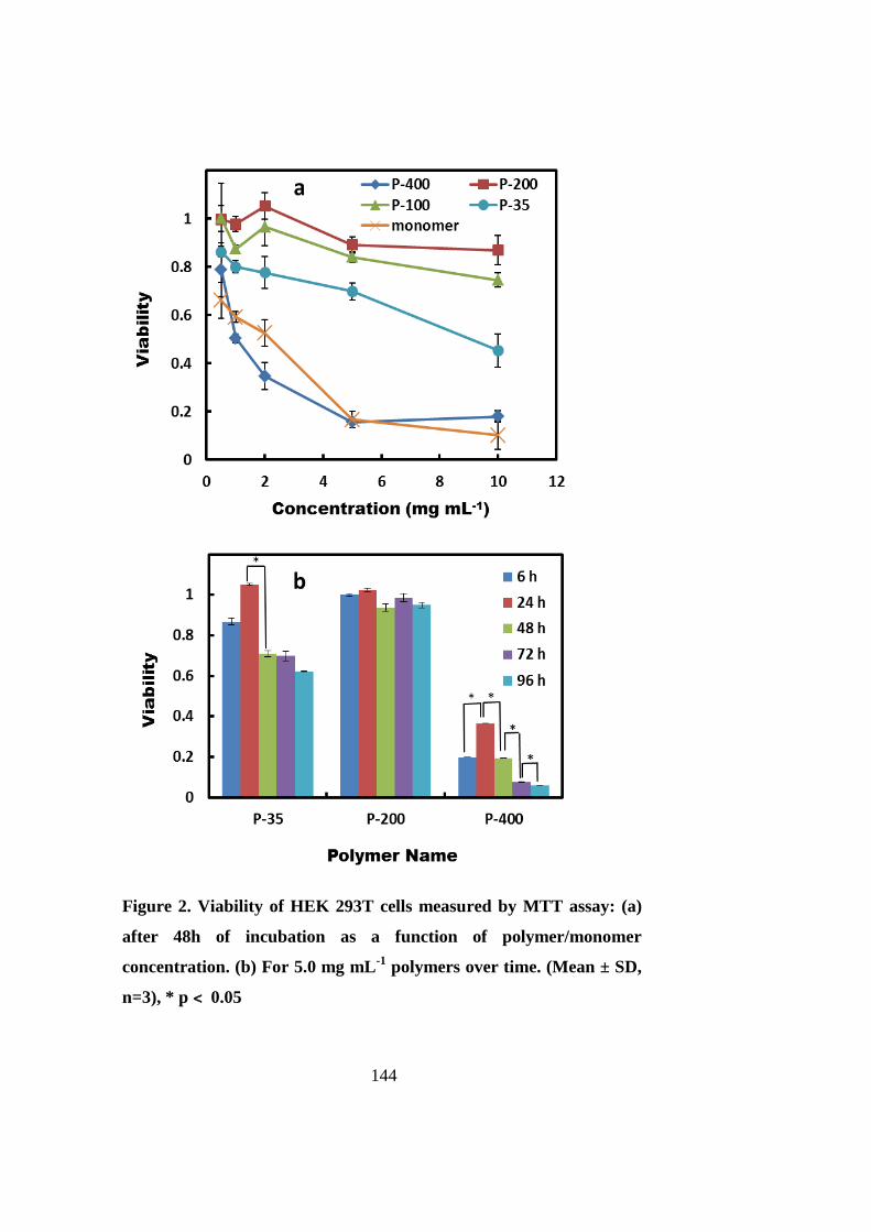
144
Figure 2. Viability of HEK 293T cells measured by MTT assay: (a)
after 48h of incubation as a function of polymer/monomer
concentration. (b) For 5.0 mg mL-1
polymers over time. (Mean ± SD,
n=3), * p ˂ 0.05
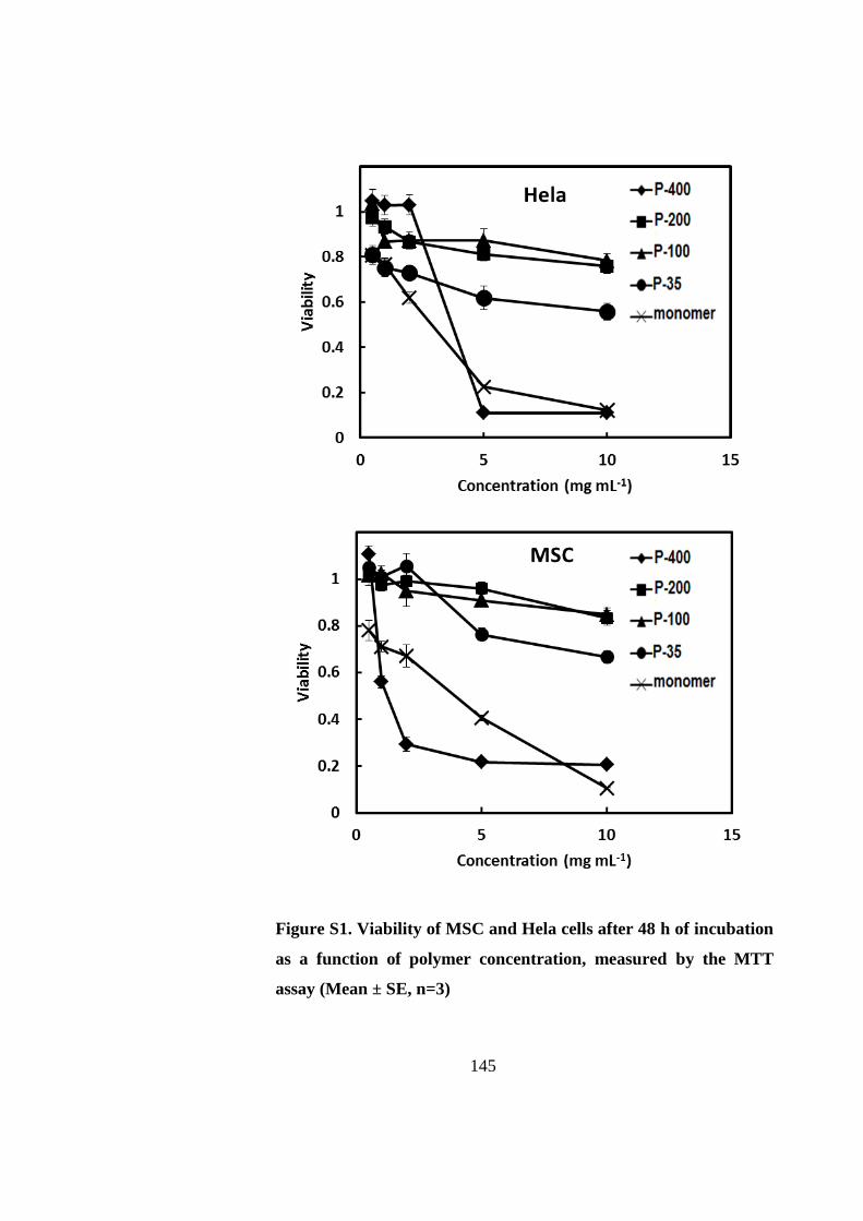
145
Figure S1. Viability of MSC and Hela cells after 48 h of incubation
as a function of polymer concentration, measured by the MTT
assay (Mean ± SE, n=3)

146
P- P-
was similar to that of P-200 and the negative control. In addition, 5.0 mg mL-1
of P-200
and P-400 solutions were added to the wells, made by Press-to-Seal™ silicone isolators on
glass slides, and allowed to precipitate by incubation at 37 °C overnight. Precipitated
polymer layers (without cell) were visualized under an inverted phase contrast microscope.
Figures 3a & b indicate that P-200 precipitates are formed as microspheres, while P-400
precipitates appeared to be an integrated, uniform and dense film. When the liquid phases
were removed and the remaining precipitates were dried, a thin and transparent layer was
observed for P-200, while P-400 precipitates were formed as a white thick film (Figures
S3a & b). The thicknesses of the polymer layers were also measured under the phase
contrast microscope. The thickness of P-200 precipitate was 49 µm (Figure 3c), whereas it
was 102 µm for P-400 (Figure 3d). The surface topography was also analysed using an
atomic force microscope (AFM). AFM topologies revealed that the surface of P-200 layer
was bumpy (Figure S3c), suggesting a porous surface. In contrast, P-400 imparted a flat
and smooth surface (Figure S3d), implying an impermeable film.
Figure S2. Viability of HEK 293T cells seeded on top of 5.0 mg mL
-1
polymers after precipitation for 48 h, measured by MTT assay (Mean
± SE, n=3).

147
Figure 3. Micrographs of 5.0 mg mL-1
of P-200 (a,c) and P-400 (b,d) in PBS
incubated at 37 °C for 24 h. (a,b) Top view of precipitated polymers. (c,d)
Section view of dried polymers indicating the thickness of precipitated layer.
a
c
b
d
49 µm
102 µm
200 µm
200 µm

148
In order to distinguish the toxicity due to apoptosis or necrosis, after HEK 293T cells were
exposed to P-35, P-200 and NIPAAm monomer, they were stained with annexin V-Alexa
Fluor 488 and propidium iodide (PI), and analysed using a flow cytometer (23, 24).
Untreated cells were employed as negative control. Results are summarized in Table 1 and
the dot plots of flow cytometric analysis are presented in Figure S4. The majority of cells
Figure S3. (a, b) Photographs of 5.0 mg mL-1
of P-200 (a) and P-400 (b) in PBS
incubated at 37°C for 24 h, and then liquid phase was removed and dried. (c, d) 3D
atomic force microscopy (AFM) topologies from the surface of a and b, respectively
(scale bars are 10 µm).
a
b
c
d
3 µ
m
1.2
µm
µµ
µm

149
in negative control (up to 83.09%) were healthy and only a few cells (6.66%) displayed
apoptotic characteristics with positive annexin stains on cell surface, while other 10.25%
were recognized as necrotics with positive PI stains. Cells revealed more necrotic damage
when exposed to P-200 (20.91±0.67%), while apoptotic cells remained at the same level as
the control. After exposure to P-35, the necrotic cell percentage nearly doubled
(40.29±1.65%) compared with P-200. However, no significant change was observed in
apoptosis induction. A similar trend was found for the cells treated with NIPAAm
monomer: 65.08±0.87% for necrosis and 7.42±2.06% for apoptosis. Results of the flow
cytometric analysis agreed with the MTT measurements. These results further indicated
that the major cell death mechanism was necrosis when cells exposed to NIPAAm or
PNIPAAm. These chemicals directly destroy cells rather than changing cell programming
for self-suicide.
Table 1. Induction of apoptosis and necrosis in HEK 293T cells.
Sample Negative Control P-200 P-35 NIPAAm
Apoptotic (%)a 6.66±0.84 6.74±0.56 5.24±1.36 7.42±2.06
Necrotic (%)a 10.25±0.79 20.91±0.67 40.29±1.65 65.08±0.87
a Values (means ± SE) from 3 independent experiments are presented.

150
a b
c d
6.77 % 3.22 %
83.15 % 6.86 %
17.84 % 3.94 %
71.79 % 6.43 %
35.15 % 2.37 % 58.86 % 6.12 %
58.80 % 3.73 %
23.15 % 11.52 %
Figure S4. The influence of PNIPAAm chain length on the stimulation of apoptosis and
necrosis in HEK 293T cells, measured using a flow cytometer. Cells were incubated
with annexin V- Alexa Fluor 488 (apoptotic cells) and PI (necrotic cells) for 48 h. (a)
Negative control without any polymer or monomer, (b) P-200, (c) P-35, (d) NIPAAm
monomer. Lower left and lower right quadrants represent live and apoptotic events.
Upper right and upper left quadrants indicate necrotic events in one typical
experiment.

151
Figure 4 shows the phase contrast micrographs of MSCs after exposure to either P-200 or
P-35. The majority of cells showd normal spread morphology when exposed to P-200
(Figure 4a), which were similar to the morphology of cells in negative control (Figure S5).
However, the cells exhibited a spherical morphology when they were exposed to the media
containing P-35 (Figure 4b). Most of cells were detached or loosened indicating cell death
(12, 25). These results were consistent with the MTT assay and the flow cytometric
measurements and further confirmed that cytotoxicity of PNIPAAm is dependent on
polymer molecular weight.
A suggested mechanism of monomer cytotoxicity is the alteration of the lipid layers of cell
membranes, which affects the permeability of the membrane (26). Likewise, the low
molecular weight PNIPAAm (P-35) was fully soluble and small enough to conveniently
penetrate the cell membrane and hinder cell normal activities (Scheme S1a). For medium-
sized PNIPAAms (P-100 and P-200), the culture temperature was higher than their LCSTs.
The formed large aggregates impeded polymer transportation through cell membrane and
thus reduced the cytotoxicity (Scheme S1b). High molecular weight PNIPAAm (P-400)
Figure 4. Morphologies of MSCs incubated for 48 h at 37 °C with 5.0
mg mL-1
of (a) P-200 or (b) P-35. Scale bars are 50µm. (150×)
b a

152
was not toxic when cells were seeded on top of the polymer coated surface. This is in
agreement with previous comparable reports that PNIPAAm coated surfaces were used for
cell sheeting (27). However, dramatic cell death for P-400 was found, when monolayer
cells on the surface were exposed to the polymer solution. The cell death may be due to
lack of nutrients and oxygen delivery from solution to the cells because entanglements of
P-400 chains at culture temperature above LCST resulted in a dense and impermeable
layer with blocked pores (Scheme S1c).
In this study, the influence of molecular weight on the cytotoxicity of PNIPAAm was
investigated. Our results indicate that low molecular weight PNIPAAm is inherently
cytotoxic and the main cell death pathway is necrosis. Moderate-sized PNIPAAms with
their degrees of polymerization between 100 and 200 are non-cytotoxic or low cytotoxic.
Due to chain entanglement of high molecular weight P-400, the cytotoxicity is dependent
on the assay method. Our findings can provide great insights for future thermoresponsive
polymer designs.
Figure S5. Morphology of MSCs incubated for 48 h
at 37 °C without polymer as control. Scale bar is
50µm. (150×)

153
Scheme S1. The effect of PNIPAAm chain length on cell viability. (a)
Short PNIPAAm chain (P-35) is toxic to cells. (b) Medium-sized
PNIPAAm chains (P-100 and P-200) are non-toxic to cells. (c) Long
PNIPAAm chain (P-400) precipitates at 37 ˚C and cover cell surface.

154
5.5 Acknowledgement
AM would like to acknowledge the Adelaide Scholarship International of the University of
Adelaide. HZ thanks the MAWA Trust and the 111 Project (B12034).

155
5.6 References
1. Langer R, Brem H, Tapper D. Biocompatibility of polymeric delivery systems for
macromolecules. Journal of Biomedical Materials Research. 1981;15(2):267-77.
2. Singh R, Singh S, Lillard JW. Past, present, and future technologies for oral
delivery of therapeutic proteins. Journal of Pharmaceutical Sciences. 2008;97(7):2497-523.
3. Yoshii E. Cytotoxic effects of acrylates and methacrylates: Relationships of
monomer structures and cytotoxicity. Journal of Biomedical Materials Research.
1997;37(4):517-24.
4. Salehpour S, Zuliani CJ, Dubé MA. Synthesis of novel stimuli-responsive
polyglycerol-based hydrogels. European Journal of Lipid Science and Technology.
2012;114(1):92-9.
5. Duncan R. The dawning era of polymer therapeutics. Nature Reviews Drug
Discovery. 2003;2(5):347-60.
6. Chang C-W, Choi D, Kim WJ, Yockman JW, Christensen LV, Kim Y-H, et al.
Non-ionic amphiphilic biodegradable PEG–PLGA–PEG copolymer enhances gene
delivery efficiency in rat skeletal muscle. Journal of Controlled Release. 2007;118(2):245-
53.
7. Exner AA, Krupka TM, Scherrer K, Teets JM. Enhancement of carboplatin toxicity
by Pluronic block copolymers. Journal of Controlled Release. 2005;106(1):188-97.
8. Yoo HS, Park TG. Biodegradable polymeric micelles composed of doxorubicin
conjugated PLGA–PEG block copolymer. Journal of controlled release. 2001;70(1):63-70.
9. Klouda L, Mikos AG. Thermoresponsive hydrogels in biomedical applications.
European Journal of Pharmaceutics and Biopharmaceutics. 2008;68(1):34-45.
10. Mellati A, Dai S, Bi J, Jin B, Zhang H. A biodegradable thermoresponsive
hydrogel with tuneable properties for mimicking three-dimensional microenvironments of
stem cells. RSC Adv. 2014;4(109):63951-61.
11. Shen Z, Mellati A, Bi J, Zhang H, Dai S. A thermally responsive cationic nanogel-
based platform for three-dimensional cell culture and recovery. RSC Advances.
2014;4(55):29146-56.
156
12. Wadajkar AS, Koppolu B, Rahimi M, Nguyen KT. Cytotoxic evaluation of N-
isopropylacrylamide monomers and temperature-sensitive poly (N-isopropylacrylamide)
nanoparticles. Journal of Nanoparticle Research. 2009;11(6):1375-82.
13. Masci G, Giacomelli L, Crescenzi V. Atom transfer radical polymerization of
N‐Isopropylacrylamide. Macromolecular Rapid Communications. 2004;25(4):559-64.
14. Xia Y, Yin X, Burke NA, Stöver HD. Thermal response of narrow-disperse poly
(N-isopropylacrylamide) prepared by atom transfer radical polymerization.
Macromolecules. 2005;38(14):5937-43.
15. Xia Y, Burke NA, Stöver HD. End group effect on the thermal response of narrow-
disperse poly (N-isopropylacrylamide) prepared by atom transfer radical polymerization.
Macromolecules. 2006;39(6):2275-83.
16. Chan P, Kurisawa M, Chung JE, Yang YY. Synthesis and characterization of
chitosan-g-poly(ethylene glycol)-folate as a non-viral carrier for tumor-targeted gene
delivery. Biomaterials. 2007;28(3):540-9.
17. Souza RD, Zahedi P, Allen CJ, Piquette-Miller M. Biocompatibility of injectable
chitosan–phospholipid implant systems. Biomaterials. 2009;30(23-24):2818-24.
18. Matyjaszewski K, Xia J. Atom transfer radical polymerization. Chemical Reviews.
2001;101(9):2921-90.
19. Patten TE, Matyjaszewski K. Atom transfer radical polymerization and the
synthesis of polymeric materials. Advanced Materials. 1998;10(12):901-15.
20. Bao H, Li L, Leong WC, Gan LH. Thermo-responsive association of chitosan-
graft-poly (N-isopropylacrylamide) in aqueous solutions. The Journal of Physical
Chemistry B. 2010;114(32):10666-73.
21. Furyk S, Zhang Y, Ortiz‐Acosta D, Cremer PS, Bergbreiter DE. Effects of end
group polarity and molecular weight on the lower critical solution temperature of poly
(N‐isopropylacrylamide). Journal of Polymer Science Part A: Polymer Chemistry.
2006;44(4):1492-501.

157
22. Uchida K, Tamura A, Yajima H. Effect of the polymer chain length of poly (N-
isopropylacrylamide) on the temperature-responsive phase transition behavior of its
conjugates with [60] fullerene. Biointerphases. 2010;5(1):17-21.
23. Vermes I, Haanen C, Steffens-Nakken H, Reutellingsperger C. A novel assay for
apoptosis flow cytometric detection of phosphatidylserine expression on early apoptotic
cells using fluorescein labelled annexin V. Journal of Immunological Methods.
1995;184(1):39-51.
24. Spagnuolo G, Galler K, Schmalz G, Cosentino C, Rengo S, Schweikl H. Inhibition
of phosphatidylinositol 3-kinase amplifies TEGDMA-induced apoptosis in primary human
pulp cells. Journal of Dental Research. 2004;83(9):703-7.
25. May JE, Morse HR, Xu J, Donaldson C. Development of a novel, physiologically
relevant cytotoxicity model: Application to the study of chemotherapeutic damage to
mesenchymal stromal cells. Toxicology and Applied Pharmacology. 2012;263(3):374-89.
26. Moharamzadeh K, Van Noort R, Brook IM, Scutt AM. Cytotoxicity of resin
monomers on human gingival fibroblasts and HaCaT keratinocytes. Dental Materials.
2007;23(1):40-4.
27. Takahashi H, Nakayama M, Yamato M, Okano T. Controlled Chain Length and
Graft Density of Thermoresponsive Polymer Brushes for Optimizing Cell Sheet Harvest.
Biomacromolecules. 2010 2010/08/09;11(8):1991-9.

158
159
CHAPTER SIX
Poly (N-isopropylacrylamide)/Chitosan Hybrid as a 6.
Three-dimensional Microenvironment for Stem Cells in
Cartilage Tissue Engineering

160

161
Poly (N-isopropylacrylamide)/chitosan hybrid as a three-
dimensional microenvironment for stem cells in cartilage tissue
engineering
Amir Mellatia, Meisam Valizadeh Kiamahalleh
a, S. Hadi Madani
b, Sheng Dai
a, Jingxiu Bi
a,
Bo Jina, Hu Zhang
a*
aSchool of Chemical Engineering, the University of Adelaide, Adelaide SA5005, Australia
bIan Wark Research Institute, University of South Australia, SA5095, Australia
*Corresponding author
E-mail: [email protected]
Tel: + 61 8 8313 3810
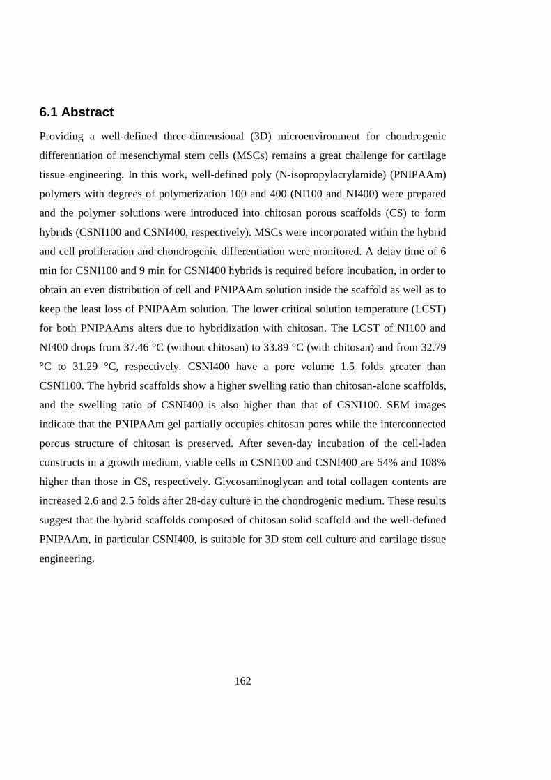
162
6.1 Abstract
Providing a well-defined three-dimensional (3D) microenvironment for chondrogenic
differentiation of mesenchymal stem cells (MSCs) remains a great challenge for cartilage
tissue engineering. In this work, well-defined poly (N-isopropylacrylamide) (PNIPAAm)
polymers with degrees of polymerization 100 and 400 (NI100 and NI400) were prepared
and the polymer solutions were introduced into chitosan porous scaffolds (CS) to form
hybrids (CSNI100 and CSNI400, respectively). MSCs were incorporated within the hybrid
and cell proliferation and chondrogenic differentiation were monitored. A delay time of 6
min for CSNI100 and 9 min for CSNI400 hybrids is required before incubation, in order to
obtain an even distribution of cell and PNIPAAm solution inside the scaffold as well as to
keep the least loss of PNIPAAm solution. The lower critical solution temperature (LCST)
for both PNIPAAms alters due to hybridization with chitosan. The LCST of NI100 and
NI400 drops from 37.46 °C (without chitosan) to 33.89 °C (with chitosan) and from 32.79
°C to 31.29 °C, respectively. CSNI400 have a pore volume 1.5 folds greater than
CSNI100. The hybrid scaffolds show a higher swelling ratio than chitosan-alone scaffolds,
and the swelling ratio of CSNI400 is also higher than that of CSNI100. SEM images
indicate that the PNIPAAm gel partially occupies chitosan pores while the interconnected
porous structure of chitosan is preserved. After seven-day incubation of the cell-laden
constructs in a growth medium, viable cells in CSNI100 and CSNI400 are 54% and 108%
higher than those in CS, respectively. Glycosaminoglycan and total collagen contents are
increased 2.6 and 2.5 folds after 28-day culture in the chondrogenic medium. These results
suggest that the hybrid scaffolds composed of chitosan solid scaffold and the well-defined
PNIPAAm, in particular CSNI400, is suitable for 3D stem cell culture and cartilage tissue
engineering.
163
6.2 Introduction
Cartilage failures due to diseases such as arthritis or daily accidents are one of the most
reasons for disabilities around the world (1). Articular cartilage has a very limited capacity
for self-healing (2). Tissue engineering is one of the most promising therapeutic strategies
by regenerating a functional articular cartilage through seeding the appropriate cells in a
three-dimensional matrix under the optimum microenvironment. However, obstacles for
clinical treatment of cartilage failure remain to be overcome, including design and
preparation of appropriate matrices as three-dimensional (3D) microenvironment for cells.
Chitosan and poly (N-isopropylacrylamide) (PNIPAAm) have been used (either separately
or together) in various forms to mimic the cellular microenvironment in cartilage tissue
engineering (3-6).
Chitosan-based matrices are an attractive group of biomaterials as scaffolds in cartilage
tissue engineering. Chitosan can promote cartilage regeneration due to its similarity with
glycosaminoglycans (GAGs) and hyaluronic acid which are major components of the
extracellular matrix (ECM) of the native articular cartilages. These biomolecules play a
great role in inducing chondrogenesis and modulating the cell morphology, differentiation
and function (4, 7, 8). PNIPAAm-based thermoresponsive hydrogels have been widely
used in biomedical applications (9). PNIPAAm undergoes a thermal phase transition in an
aqueous solution at a temperature termed as lower critical solution temperature (LCST).
The LCST of PNIPAAm is close to the human physiological temperature at which cells
reside in comfort. This fact has made PNIPAAm as one of the most studied
thermoresponsive polymers.
As a thermoresponsive moiety, poly (N-isopropylacrylamide) (PNIPAAm) can be
introduced to the chitosan through a variety of approaches. PNIPAAm-based
thermoresponsive chitosan has been prepared in various methods, including
interpenetrating polymer networks (IPN) (10, 11), semi-IPN (11, 12), surface grafted
membranes (13), chemically cross-linked hydrogels in forms of discs (14-16), films (16,
17) , nanoparticles (18-22) and solutions (5, 6, 23-26).To the best of our knowledge, the

164
hybrid matrix composed of chitosan and PNIPAAm ( without any chemical bond between
chitosan and PNIPAAm or cross-linking between chitosan and/or PNIPAAm molecules),
and its performance as cell microenvironment have not been reported yet.
Physical, mechanical and chemical properties of PNIPAAm polymers are molecular
weight-dependent (27-29). Our previous study has demonstrated that its cytotoxicity also
depends on the PNIPAAm molecular chain length (Chapter 5). However, the effect of
polymer molecular weight on cellular activity in a 3D microenvironment remains to be
investigated. In this study, well-defined PNIPAAms were prepared through atom transfer
radical polymerization (ATRP) and the polymer solution was introduced into chitosan
porous scaffolds to form hybrids upon incubating at 37 °C. These hybrids may benefit
from both improved cellular compatibility of controlled PNIPAAm as well as good
properties of chitosan in chondrogenesis of MSCs. PNIPAAm and PNIPAAm/chitosan
hybrids were characterized and mesenchymal stem cell (MSC) proliferation within hybrid
matrices was evaluated. The hybrid structure was further used as a novel scaffold for
chondrogenic differentiation of MSCs.
6.3 Materials and methods
6.3.1 Materials
All chemicals were of analytical grades and used directly without further purification,
unless otherwise mentioned.
6.3.2 Preparation of scaffolds
2.0 wt% chitosan (MW of 200-300 kDa, Acros Organic, NJ) solutions in 0.2 M acetic acid
were prepared. 380 µL of chitosan solution was added to each well of 24-well plates and
were frozen at -80 °C overnight. The frozen samples were lyophilized in an ALPHA 1-
2LD plus freeze-dryer (CHRIST, Germany) for 48 h. Porous chitosan scaffolds (CS) were
washed with 0.05 M NaOH for 10 min and rinsed twice in water and twice in PBS (Gibco-
BRL, Grand Island).

165
Well-defined PNIPAAms were prepared through ATRP. To prepare PNIPAAm with a
degree of polymerization (DP) of 100, the monomer n-isopropylacrylamide (NIPAAm,
97%, Sigma-Aldrich) was purified by recrystallization in n-hexane. 1.0 g (8.8 mmol)
NIPAAm, 8.7 mg (0.088 mmol) copper chloride (CuCl, Sigma-Aldrich) were dissolved in
2.0 mL 2-propanol, transferred to a dried Schlenk flask and fitted with a septum. Three
freeze–pump–thaw cycles were conducted before addition of 24.0 µl (0.088 mmol) of
Tris[2-(dimethylamino)ethyl]amine (Me6Tren, 97%, Sigma-Aldrich) using a nitrogen-
purged syringe. The solution was stirred for 40 min at room temperature to allow
formation of the CuCl/Me6TREN complex. 11.0 µl (0.088 mmol) of ethyl 2-
chloropropionate (ECP, Sigma-Aldrich) was added to start polymerization using an air-free
syringe. After 8 h reaction at 25 °C, the solution was exposed to air, diluted by adding
tetrahydrofuran and passed through an alumina column to separate the catalyst. The
polymer was precipitated in diethyl ether, filtered and dried in an oven.
PNIPAAm with DPs of 100 and 400 (NI100 and NI400) solutions of 80 mg/mL (in PBS)
were prepared. 50 µL of the PNIPAAm solution was pipetted to the top of chitosan
scaffolds in 24-well plates. The plates were transferred to an oven at 40 °C to form
CS/NI100 (CSNI100) and CS/NI400 (CSNI400) hybrids.
6.3.3 Dynamic light scattering
Dynamic light scattering (DLS) measurements were carried out using 1.0 mg/mL of the
PNIPAAms in MilliQ water. The hydrodynamic diameters (dh) were recorded at different
measurement temperatures using a Malvern Zetasizer (Nano-ZS). The DLS data were
collected on an autocorrelator with a detection angle of scattered light at 90°. The
CONTIN software package was used to analyze the intensity autocorrelation functions.
6.3.4 Thermal analysis
50 µL of NI100 or NI400 aqueous solution (80 mg/mL) was pipetted on top of chitosan
scaffolds and were left at room temperature at intervals of 3, 6, 9, 12, 15 and 18 min before
166
transferred to a 40 °C oven to solidify the PNIPAAm. Thermal gravimetric analysis (TGA)
was carried out using LABSYS TG-DTA/DSC (SETARAM Instrumentation, France).
Dried samples were preheated at 100 °C for 5 min to remove moisture and thermal
decomposition profiles were recorded at a heating rate of 10 °C/min between 100 °C and
700 °C under nitrogen gas.
Differential scanning calorimetry (DSC) was performed using a LABSYS TG-DTA/DSC
(SETARAM Instrumentation, France). NI100 and NI400 aqueous solutions as well as
CSNI100 and CSNI400 hydrogels were prepared using PBS as a solvent. Samples were
heated up from 25 to 60 °C at a rate of 0.5 °C/min under nitogen gas.
6.3.5 Gas absorption
Nitrogen gas adsorption experiments were carried out at 77 K using a Belsorp-Max gas
adsorption apparatus (Bel, Japan). Samples were degassed prior to the adsorption
experiments at ambient temperature and a background pressure of 10-5 kPa for 6 h. Ultra
high purity (>99.999%) helium and nitrogen (Coregas, Australia) were used for dead-space
measurements and nitrogen adsorption experiments, respectively. Pore size distributions
(PSD) were calculated based on the BJH method (30), and BET surface areas were
calculated using BET method (31).
6.3.6 Swelling ratio
Dried samples of the chitosan/PNIPAAm hybrid were prepared at the optimum incubation
time based on TGA results. Chitosan scaffolds were prepared through the same procedure
without addition of PNIPAAm. Swelling ratio was determined according to the previous
reports (13, 32). Samples were weighed and then immersed into the PBS solution at
various temperatures ranging from 45 °C to 4 °C for 8 h. Swollen samples were taken out
from the buffer solution, wiped gently with a filter paper to remove free water from surface
and weighed. The swelling ratio (SR) was defined as SR= (Ws-Wd) /Wd , where Ws and Wd
were the weights of the swollen and the dry samples, respectively.
167
6.3.7 Preparation of cell-laden scaffolds
Mesenchymal stem cell line (10T1/2, RIKEN cell bank, Japan) was cultured in Dulbecco's
Modified Eagle's Medium (DMEM, Gibco-BRL, Grand Island) supplemented with 10%
fetal bovine serum (FBS, Gibco-BRL, Grand Island), 100 U/mL of penicillin (Gibco-BRL,
Grand Island), 100 mg/mL of streptomycin (Gibco-BRL, Grand Island) and 2 mM/L L-
glutamine (Gibco-BRL, Grand Island). The cells were incubated at 37°C in a humidified
atmosphere in the presence of 5% CO2. Cells were trypsinized from flasks and
resuspended in a fresh culture medium at a density of 4.0×10⁷ cells/mL.
NI100 and NI400 solutions of 160 mg/mL (in PBS) were prepared (pH of 7.4) and
sterilized by autoclave. Cell suspension and polymer solution were mixed to prepare a
mixture of cell and polymer at a cell concentration of 2.0 × 10⁷ cells/mL and a final
polymer concentration of 80 mg/mL. Chitosan scaffolds (neutralized and washed) were
sterilized using 75% ethanol, under UV light for 3 h. The solvent was exchanged (6×) with
the sterile PBS. 50 µL of the cell/polymer mixture was pipetted to the top of chitosan
scaffolds in 24-well plates. The same cell concentrations were prepared by mixing cells
and PBS without PNIPAAm as CS samples. Well plates were transferred to incubator at
predetermined times, based on TGA results and incubated for 1 h at 37˚C to form hybrid
hydrogels. 2.0 mL of fresh growth medium was topped up to each well and kept in a
humidified incubator at 37˚C and 5% CO2. Medium was replaced with fresh medium every
day.
6.3.8 Scanning electron microscopy
Chitosan or chitosan/PNIPAAm hybrid samples were freeze-dried before gold coating.
Cell-laden constructs (after 3 days incubation with growth medium) were first fixed in the
EM fixative (4% paraformaldehyde / 1.25% glutaraldehyde (ProSciTech, Australia) in
PBS + 4% sucrose (Chem Supply, Australia), pH of 7.2), washed in a washing buffer (PBS
+ 4% sucrose), and post-fixed in 2% OsO4 (ProSciTech, Australia) in water. Fixed
168
samples were dehydrated in serial ethanol followed by immersion in hexamethyldisilazane
(HDMS, ProSciTech, Australia)/ethanol (1:1) and 100% HDMS. Samples were air-dried
and gold coated. The morphologies of samples were observed by a Philips XL 30 FEG
scanning electron microscope (SEM) (FEI, USA).
6.3.9 Mitochondrial activity measurement
Growth medium of cell-laden constructs was replaced with fresh medium at predefined
times and 100 µL (5 mg/mL in PBS) of 3-(4,5-Dimethylthiazol-2-yl)-2,5-
diphenyltetrazolium bromide (MTT, Molecular Probes, OR) were added to each well and
incubated for 4 h at 37˚C. All liquid was removed from the wells and 2.0 mL dimethyl
sulfoxide (DMSO) was added to each well to ensure complete solubilization of formazan
crystals. After 1 h further incubation, constructs were transferred to centrifuge tubes and
briefly vortexed to homogenize before centrifugation. The absorbance of supernatant was
read using an ELx808 microplate reader (BioTek, USA) at 570 nm.
6.3.10 Confocal laser scanning microscopy
Live/Dead® viability/cytotoxicity kit (Molecular Probes, OR) was used to stain live and
dead cells. 1.0 μM of acetomethoxy derivate of calcein (calcein AM) and 2.5 μM of
ethidium homodimer-1 (EthD-1) working solutions were prepared freshly according to the
manufacturer’s protocol. At day 1 and 7, the growth medium was removed and constructs
were washed with 1.0 mL of preheated PBS. The liquid was replaced with 2.0 mL of dye
working solution and further incubated at 37˚C for 45 min. Samples were washed with
PBS to remove unreacted dyes. For cell detachment evaluation, cells were detached by
lowering the temperature to room temperature during staining and cell suspension was
collected after washing the construct. The suspension was centrifuged to pellet the cells.
Cell pellet was rinsed carefully with PBS and resuspended in fresh PBS. Samples were
transferred carefully to a chamber made from coverslips and Press-to-Seal™ silicone
isolators (Molecular Probes, OR) and observed under a Leica SP5 spectral scanning

169
confocal microscope (Leica Microsystems, Germany) equipped with a temperature
controlled stage to keep the thermoresponsive hydrogels at 37˚C. Excitation wavelengths
were set to 494 and 528 nm and emission wavelengths were at 517 and 617 nm for live
(green) and dead (red) cells, respectively.
6.3.11 Chondrogenic induction
Cell-laden CSNI400 constructs were prepared as pre-described at a cell density of 1.25 ×
10 6 cells/well. 2.0 mL of chondrogenic medium containing high glucose-DMEM, 1%
insulin, transferrin, selenous acid (ITS)+Permix (BD Bioscience, MA), 10-7
M
dexamethasone (Sigma-Aldrich), 10.0 ng/mL transforming growth factor-beta 1(TGF-β1)
(Peprotech, NJ), 50.0 µg/mL ascorbate-2-phosphate (Sigma-Aldrich), 100.0 U/mL of
penicillin, 100.0 mg/mL of streptomycin and 2.0 mM/L L-glutamine was added to each
well and kept in an incubator at 37 °C and 5% CO2 for continuous 28 days. The medium
was being changed every day. Eight wells at sampling days were taken out for biochemical
analysis.
6.3.12 Biochemical assays
DNA, glycosaminoglycan (GAG) and total collegen content were quantified by Hoechst
33258, DMMB and hydroxyproline assays as described previously (33, 34). At each time
point constructs were collected, rinsed with prewarmed PBS, freeze-dried for 48 h and
incubated in papain (Sigma-Aldrich) solution at 60 °C for 16 h to digest. The supernatant
of the papain-digested hydrogels was used for biochemical assays.
DNA content was measured by the Hoechst 33258 assay. 30.0 µL of the supernatant of the
papain-digested constructs was added to 3.0 mL of Hoechst 33258 dye (Sigma-Aldrich)
solution in TNE buffer (10 mM Tris–HCl/100 mM NaCl/1 mM EDTA) and the intensity
was read using a RF-5301PC fluorospectrometer (Shimadzu, Japan) at 360 nm excitation
and 460 nm emission. The corresponding DNA amount was calculated based on a ds-calf
Thymus DNA type I (Sigma-Aldrich) standard curve.

170
For GAG analysis, the supernatant was reacted with 1,9-dimethylmethylene blue (DMMB,
Sigma-Aldrich) in PBE buffer solution (100 mM sodium phosphate buffer/10 mM
Na2EDTA) and absorbance was read at 525 nm by the spectrophotometer. Chondroitin
sulphate (Sigma-Aldrich) was served to generate an standard curve.
Total collagen was evaluated by the hydroxyproline assay. Papain-digested supernatant
was hydrolyzed in 6 N HCl for 18 h at 110 °C, then neutralized and combined with
chloramine-T (Sigma-Aldrich) soultion followed by incubation at room temperature for 20
min. The solution was mixed with Ehrlich’s reagent, vortexed and further incubated for 30
min at 60 °C. Finally, the absorbance was read at 550 nm using the spectrophotometer and
collagen content was computed according to the trans-4-hydroxy-L-proline (Sigma-
Aldrich) standard curve. All values of biochemical assays were normalized to the dry
weight of the constructs.
6.3.13 Statistical analysis
All measurements were performed in triplicates for every measure points unless otherwise
stated. Data obtained from our experiments are presented as mean ± SD (standard
deviation). Statistical significance was determined by application of student’s t-test. The
differences were considered to be significant when P < 0.05.
6.4 Results and discussion
6.4.1 Scaffold preparation and characterization
The ATRP of NIPAAm using ECP as an initiator and CuCl/Me6TREN as the catalyst was
previously demonstrated to be an effective method to achieve PNIPAAms with well-
defined and narrow-dispersed molecular weights (35). Therefore, we employed this
technique to prepare PNIPAAms with DPs of 100 (molecular weight (MW) =11300) and
400 (MW=45200) by adjusting the concentration ratio of the monomer to the initiator
(Table 1). NI100 and NI200 have very similar properties as evidenced in Chapter 5. P-100

171
Table 1. Summary of reaction conditions and characteristics of the PNIPAAms
Sample [M]:[I]:[CuCl]:[L]a Mn
b dh
(nm)
c
NI100 100:1:1:1 11300 6.65±0.14
NI400 400:1:1:1 45200 12.47±0.65
a M: monomer, I: initiator, L: ligand
b Number average molecular weight
c Hydrodynamic diameter, measured by DLS, (Mean ± SD, n=3)
may form smaller particles under the precipitation conditions in comparison to P-200. But
in this chapter, we would like to investigate the effect of different degree of polymerization
of hydrogels on cell growth in 3D; and either P-100 or P-200 could be chosen for this
purpose. The hydrodynamic diameter (dh) of NI400 molecules (12.47 nm) was almost
twice the dh of NI100 (6.65 nm) as measured by DLS. It was expected because the DP of
NI400 was higher than that of NI100.
Ice removal by lyophilization of frozen chitosan solution generates a porous structure (4).
Solution concentration and freezing temperature affect the final average pore size as
reported previously (36). Thus, we selected preparation conditions in order to obtain pore
sizes of around 100 µm. This is large enough for MSCs with an average cell size of 10-15
µm (37).
The chitosan/PNIPAAm hybrid constructs were prepared by addition of PNIPAAm
solutions on top of chitosan scaffolds. The PNIPAAm solution penetrated through the
pores of chitosan and the hybrid structure formd by raising the environmental temperature
to above LCST of PNIPAAm. The preparation process is illustrated in Scheme 1.

172
After addition of the PNIPAAm solution on top of chitosan scaffold, it penetrates into the
porous structure of chitosan, passes through the pores and eventually exits from the bottom
of the construct. It is important to incubate the hybrid structure at a predetermined
temperature above the LCST just in time when the PNIPAAm spreads over the whole
depth but still retains inside the construct. To find such an optimum time, CSNI100 and
CSNI400 were transferred to an oven at various intervals after addition of PNIPAAm
solution and the samples were analyzed by TGA. Figures 1a and 1b show the thermal
degradation curves of CSNI100 and CSNI400, respectively. As expected, both samples
exhibited the degradation in two stages, which are due to thermal decompositions of
chitosan and PNIPAAm, respectively (38). The degradation temperature was almost
constant for both samples at different intervals. However, the percentage of weight loss
Scheme 1. Preparation of cell-laden chitosan/PNIPAAm hybrids.

173
Figure 1. Thermogravimetric analysis of (a) CSNI100
and (b) CSNI400 samples prepared by transferring the
PNIPAAm-loaded scaffolds to a temperature above its
LCST (40 °C) at various intervals after addition of
PNIPAAm solution on top of chitosan scaffolds. (c)
The ratio of weight percent changes of PNIPAAm to
chitosan versus time, calculated from (a) and (b).
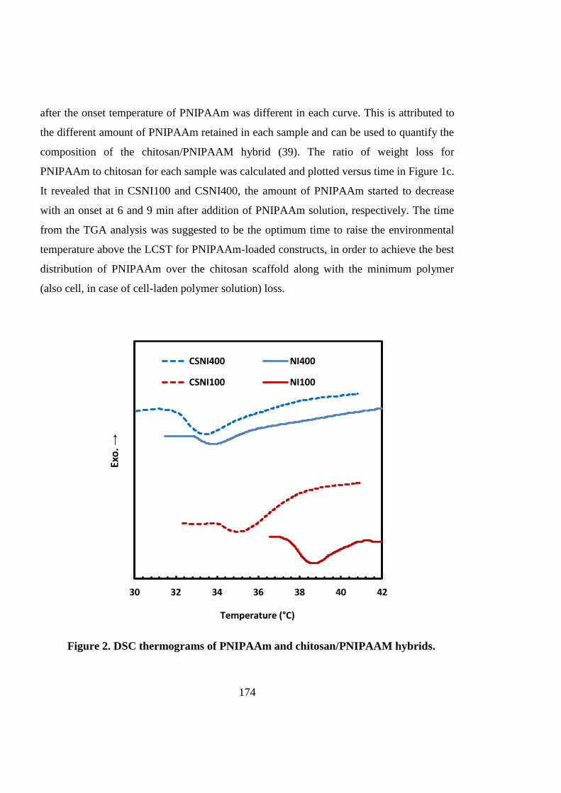
174
after the onset temperature of PNIPAAm was different in each curve. This is attributed to
the different amount of PNIPAAm retained in each sample and can be used to quantify the
composition of the chitosan/PNIPAAM hybrid (39). The ratio of weight loss for
PNIPAAm to chitosan for each sample was calculated and plotted versus time in Figure 1c.
It revealed that in CSNI100 and CSNI400, the amount of PNIPAAm started to decrease
with an onset at 6 and 9 min after addition of PNIPAAm solution, respectively. The time
from the TGA analysis was suggested to be the optimum time to raise the environmental
temperature above the LCST for PNIPAAm-loaded constructs, in order to achieve the best
distribution of PNIPAAm over the chitosan scaffold along with the minimum polymer
(also cell, in case of cell-laden polymer solution) loss.
30 32 34 36 38 40 42
Exo
. →
Temperature (°C)
CSNI400 NI400
CSNI100 NI100
Figure 2. DSC thermograms of PNIPAAm and chitosan/PNIPAAM hybrids.
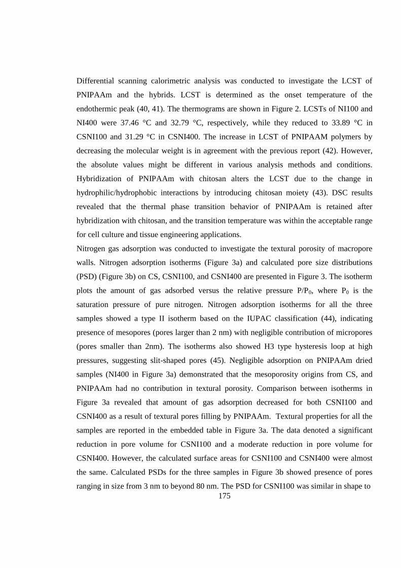
175
Differential scanning calorimetric analysis was conducted to investigate the LCST of
PNIPAAm and the hybrids. LCST is determined as the onset temperature of the
endothermic peak (40, 41). The thermograms are shown in Figure 2. LCSTs of NI100 and
NI400 were 37.46 °C and 32.79 °C, respectively, while they reduced to 33.89 °C in
CSNI100 and 31.29 °C in CSNI400. The increase in LCST of PNIPAAM polymers by
decreasing the molecular weight is in agreement with the previous report (42). However,
the absolute values might be different in various analysis methods and conditions.
Hybridization of PNIPAAm with chitosan alters the LCST due to the change in
hydrophilic/hydrophobic interactions by introducing chitosan moiety (43). DSC results
revealed that the thermal phase transition behavior of PNIPAAm is retained after
hybridization with chitosan, and the transition temperature was within the acceptable range
for cell culture and tissue engineering applications.
Nitrogen gas adsorption was conducted to investigate the textural porosity of macropore
walls. Nitrogen adsorption isotherms (Figure 3a) and calculated pore size distributions
(PSD) (Figure 3b) on CS, CSNI100, and CSNI400 are presented in Figure 3. The isotherm
plots the amount of gas adsorbed versus the relative pressure P/P0, where P0 is the
saturation pressure of pure nitrogen. Nitrogen adsorption isotherms for all the three
samples showed a type II isotherm based on the IUPAC classification (44), indicating
presence of mesopores (pores larger than 2 nm) with negligible contribution of micropores
(pores smaller than 2nm). The isotherms also showed H3 type hysteresis loop at high
pressures, suggesting slit-shaped pores (45). Negligible adsorption on PNIPAAm dried
samples (NI400 in Figure 3a) demonstrated that the mesoporosity origins from CS, and
PNIPAAm had no contribution in textural porosity. Comparison between isotherms in
Figure 3a revealed that amount of gas adsorption decreased for both CSNI100 and
CSNI400 as a result of textural pores filling by PNIPAAm. Textural properties for all the
samples are reported in the embedded table in Figure 3a. The data denoted a significant
reduction in pore volume for CSNI100 and a moderate reduction in pore volume for
CSNI400. However, the calculated surface areas for CSNI100 and CSNI400 were almost
the same. Calculated PSDs for the three samples in Figure 3b showed presence of pores
ranging in size from 3 nm to beyond 80 nm. The PSD for CSNI100 was similar in shape to
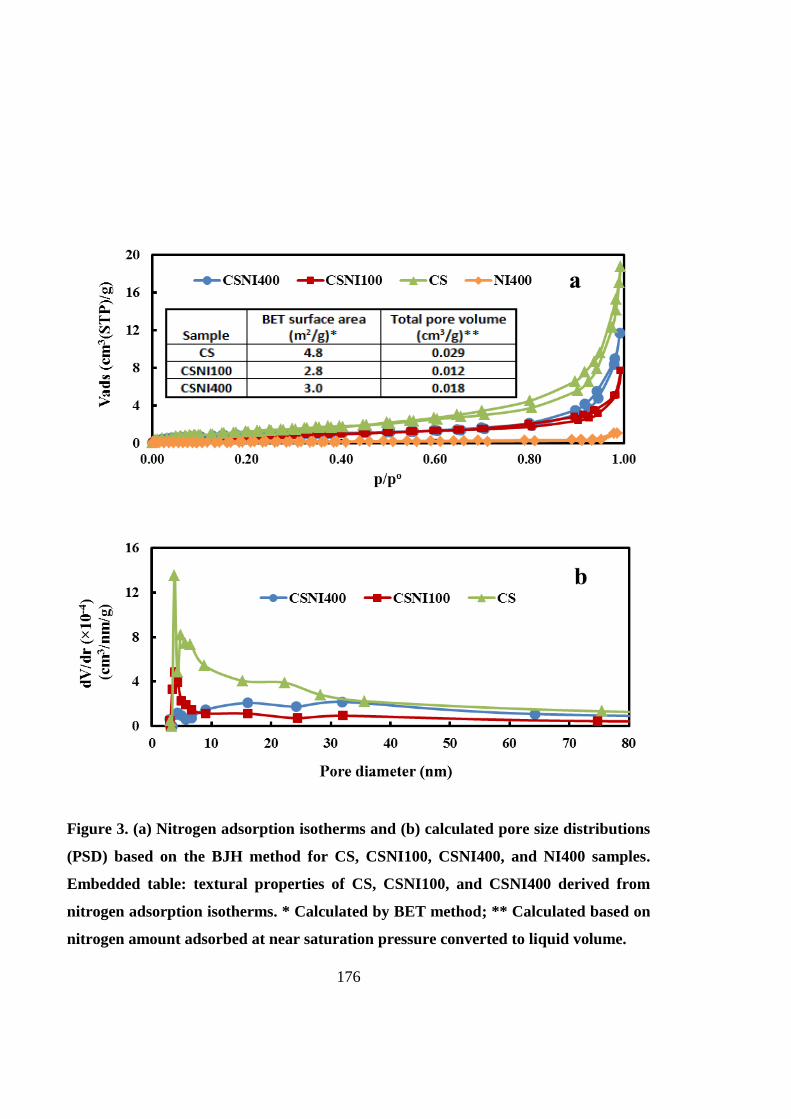
176
Figure 3. (a) Nitrogen adsorption isotherms and (b) calculated pore size distributions
(PSD) based on the BJH method for CS, CSNI100, CSNI400, and NI400 samples.
Embedded table: textural properties of CS, CSNI100, and CSNI400 derived from
nitrogen adsorption isotherms. * Calculated by BET method; ** Calculated based on
nitrogen amount adsorbed at near saturation pressure converted to liquid volume.

177
that for CS but with a smaller intensity, suggesting a uniform and non-selective pore-filling
mechanism. On the other hand, the PSD for CSNI400 followed a selective pattern. Pores
with sizes smaller than 30 nm in CSNI400 were more favorable sites for adsorption. The
textural porosities play a significant role in micro and macroscale behaviors of scaffold
(46, 47) and the properties can be tuned for cell proliferation and differentiation. Such
nano-sized pores filled with thermoresponsive polymers have also been employed for
encapsulation of bioactive molecules and sustained release of these biomolecules
facilitates generation of engineering tissues (48).
2
4
6
8
10
12
14
16
0 10 20 30 40 50
Sw
ell
ing
R
ati
o
Temperature (°C)
CSNI400 CSNI100 CS
Figure 4. Swelling ratio of CS, CSNI100 and CSNI400 in PBS in the
temperature range from 4-45 C (Mean ± SD, n=3).

178
The swelling behavior of CS, CSNI100 and CSNI400 samples is shown in Figure 4. The
hybrid constructs had a higher swelling ratio (SR) than chitosan alone, indicating a higher
equilibrium water content. It is attributed to the presence of hydrophilic PNIPAAm chains
in solution. Similar behavior has been reported for copolymers of chitosan and PNIPAAm
(16). Furthermore, CSNI400 possessed 1.33 folds water content higher than CSNI100. It
may occur due to a higher pore volume of CSNI400. The pore volume of CSNI400 was
1.50 folds larger than that of CSNI100 as calculated from gas adsorption, which allowed
more water content in the swollen hybrid structure. The ratio of pore volume of CSNI400
to CSNI100 was interestingly in good agreement with the order of magnitude of the
swelling ratio between two hybrid matrices. The graph also indicated that SR remained
constant when temperature changed, even above LCST. SR often decreases for PNIPAAm-
based thermoresponsive hydrogels beyond their LCST (38). PNIPAAm becomes
hydrophobic above LCST and hence, expels water from the gel. However, little water was
expelled from the chitosan/PNIPAAm hybrids because there were no chemical bonds
between PNIPAAm and chitosan or cross-linking between PNIPAAm molecules.
Therefore, above LCST, PNIPAAm molecules underwent a coil-to-globule transition and
discharge water. Nevertheless, chitosan did not collapse and retained its swollen structure.
As a result, the expelled water from PNIPAAm remained in the chitosan network.
The morphology and porous structure of the constructs were studied using SEM. The
scaffold from chitosan alone in Figure 5a had a porous internal structure which was
interconnected with random pore sizes and shapes. The majority of pores were between 10
and 100 µm. The pore walls were thin with a thickness of around 1 µm. Pore wall surfaces
possessed a soft texture in microscale, with no visible pore or wrinkle. Pores were partially
filled with PNIPAAm polymer after addition of CSNI100 (Figure 5b) and CSNI400
(Figure 5c). However, the hybrids preserved their porous structure. CSNI100 macropores
seem to be slightly more occupied probably due to shorter chain lengths of NI100. Partial
occupation of pores may not hindered cell activities, because of its soft and flexible
structure. Cell-laden CSNI100 and CSNI400 micrographs are shown in Figures 5d-f. Cells
were located within the porous structure and kept their spherical shape which is acceptable

179
Figure 5. SEM micrograph of (a) CS , (b) CSNI100, (c) CSNI400; (500×), (d)
cell-laden CSNI100, (e) cell-laden CSNI400; (10000×), and (f) cell-laden
CSNI400 (5000×). Cell-laden constructs were incubated for 3 days. Yellow
arrows and dashed circle point cells.
a d
c f
b e

180
as they were cultured within a 3D microenvironment rather than a 2D monolayer. The
texture of pore walls was altered with an uneven and wrinkled surface. It can be due to the
ECM components excreted by cells. Sample preparation for the cell-encapsulating scaffold
as well as various ions and ingredients in cell culture medium may also affect the
topography of scaffolds. Macropores are a determinant parameter of cell matrices. It
should provide adequate space for efficient cell seeding, cellular interactions, migration,
proliferation, and ECM deposition (49). They also contribute to the scaffold mechanical
property which is an important microenvironmental variable (50).
6.4.2 Cell proliferation
The MTT assay was conducted to investigate cell viability and proliferation when MSCs
were cultured in chitosan scaffold and chitosan/PNIPAAm hybrids. The yellow-colored
water-soluble tetrazolium salt, MTT, converts to water insoluble, purple-coloured
formazan crystals as a consequence of its metabolization by mitochondrial dehydrogenase
of live cells. Damaged or dead cells do not have any mitochondrial dehydrogenase activity.
Therefore, the optical density of the soluble crystal represents the amount of viable cells.
The cell viabilities were at the same level for CS, CSNI100 and CSNI400 at day 1 as
shown in the blue bar in Figure 6a. The viabilities decreased for all three groups at day 7 in
comparison with day 1. However, cell number in CSNI400 was significantly higher
(P<0.05) than that in CSNI100, and CSNI100 was greater than CS. It might happened
because some cells died when cultured in a new 3D microenvironment and then started to
proliferate which was more significant in CSNI400. The photographs of cell-laden
constructs incubated with MTT at day 7 are shown in Figures 6b-d. The purple-coloured
viable cells were mostly located near to the top surface of CS scaffold (panel b). In
contrast, viable cells were well distributed over the whole depth of CSNI100 (panel c) and
CSNI400 (panel d) constructs, and the color was even more intense and uniformly
dispersed in CSNI400.
The cell viability was further visualized by staining the live and dead cells encapsulated
within the constructs. This assay is based on a two-color fluorescence dye. Viable cells are

181
stained by cell-permeant calcein AM. Non-fluorescent calcein AM is converted to
intensely fluorescent calcein as a result of enzymatic intracellular esterase activity of live
cells. Cell-impermeant Ethidium homodimer-1 dye can only enter dying and dead cells
with damaged membranes and binds to their DNA, and the DNA/dye complex
consequently emits red fluorescence. Stained CS, CSNI100 and CSNI400 constructs were
observed under a confocal laser scanning microscope. Green and red spots in Figure 4
display live and dead cells, respectively. Live cell density in CS (Figure 7a) was less than
CSNI100 (Figure 7b). The viable cell number was the highest in CSNI400 (Figure 7c) in
comparison to CS and CSNI100, while comparatively more dead cells were
distinguishable in the CS construct. Live/dead staining results were in agreement with the
MTT readings. High live to dead cell ratio of CS/NI hybrids supports the idea that the cell
*
b
c
d
Figure 6. (a) Mitochondrial activity quantification of MSCs cultured in CS,
CSNI100 and CSNI400. The MTT assay was performed at day 1 and 7 after
incubation (Mean ± SD, n=3; * p ˂ 0.05). Photograph of Cell-laden (b) CS, (c)
CSNI100, and (d) CSNI400 constructs stained with MTT at day 7.

182
viability decrement between day 1 and 7 in MTT assay was not a continuous phenomenon.
After culturing MSCs in growth medium for 7 days, cells were detached from the scaffolds
by simply lowering the temperature below the LCST of PNIPAAm. The majority of cells
were recovered as a cell suspension (Figure 7e), while a few cells were entrapped within
the scaffolds (Figure 7d). It suggests that this hybrid system can also be used as a platform
for 3D stem cell expansion. In this approach, stem cells are cultured in a 3D
Figure 7. Confocal laser scanning images of MSCs cultured in: (a) CS, (b) CSNI100 and
(c) CSNI400 at day 7 (10× oil immersion objective, scale bars 250 μm). After cells were
detached from CSNI400 at day 7 by reducing the temperature to room temperature, (d)
a few cells retained in the scaffold, and (e) the majority of cells were recovered and
suspended in the solution (20× oil immersion objective, scale bars 100 μm).
c b
d e
a

183
microenvironment rather than conventional monolayer cultures. This system mimics their
native 3D niche which is essential to preserve cell biological capabilities and to govern cell
fate (51, 52). Subsequently, cells can be detached at confluency or use time, by reducing
the temperature and without using detrimental enzymes.
In general, these results suggest that stem cells were biologically more active in
PNIPAAm-loaded constructs in comparison with chitosan alone, probably due to more
swollen structure as shown in SR studies. The highly hydrated and swollen structure of
microenvironment provides larger space which facilitates cell migration, nutrient delivery,
waste removal and ECM secretion. In addition, PNIPAAm may promote cell adhesion to
the chitosan macropore walls during its shrinkage above LCST. CSNI400 was also more
favorable for cell proliferation in a same manner because of its bigger SR originated from
greater textural pore volume.
6.4.3 Chondrogenic differentiation
Chondrogenic differentiation of MSCs in the hybrid structure was evaluated using
biochemical assays. The CSNI400 has shown a better cell proliferation rate. Therefore, this
structure was chosen for evaluation in the application of cartilage tissue engineering. By
continuously incubating MSC in the CSNI400 hybrid structure with the differentiating
medium for 28 days, ECM (GAGs and total collagen) production was monitored to
confirm cartilage formation.
Cell proliferation was assessed by the Hoescht 33258 assay. The Hoescht assay results
(Figure 8a) indicate that the DNA content increased from 0.73 µg DNA/mg dry scaffold at
day 14 to 1.15 µg DNA/mg dry scaffold at day 28, suggesting the increase in total cell
number. The DMMB and the hydroxyproline assay were employed to quantify GAG and
collagen deposition, respectively. The GAG level (Figure 8b) increased 2.6 folds from day
14 to day 28, and a similar increment in total collagen accumulation was also noted in
Figure 8c. GAG and collagen are the main components of cartilagous tissues. Enhanced
GAG and collagen deposition revealed the chondrogenic differentiation of MSCs within
the 3D microenvironment provided by the chitosan/PNIPAAm scaffold.
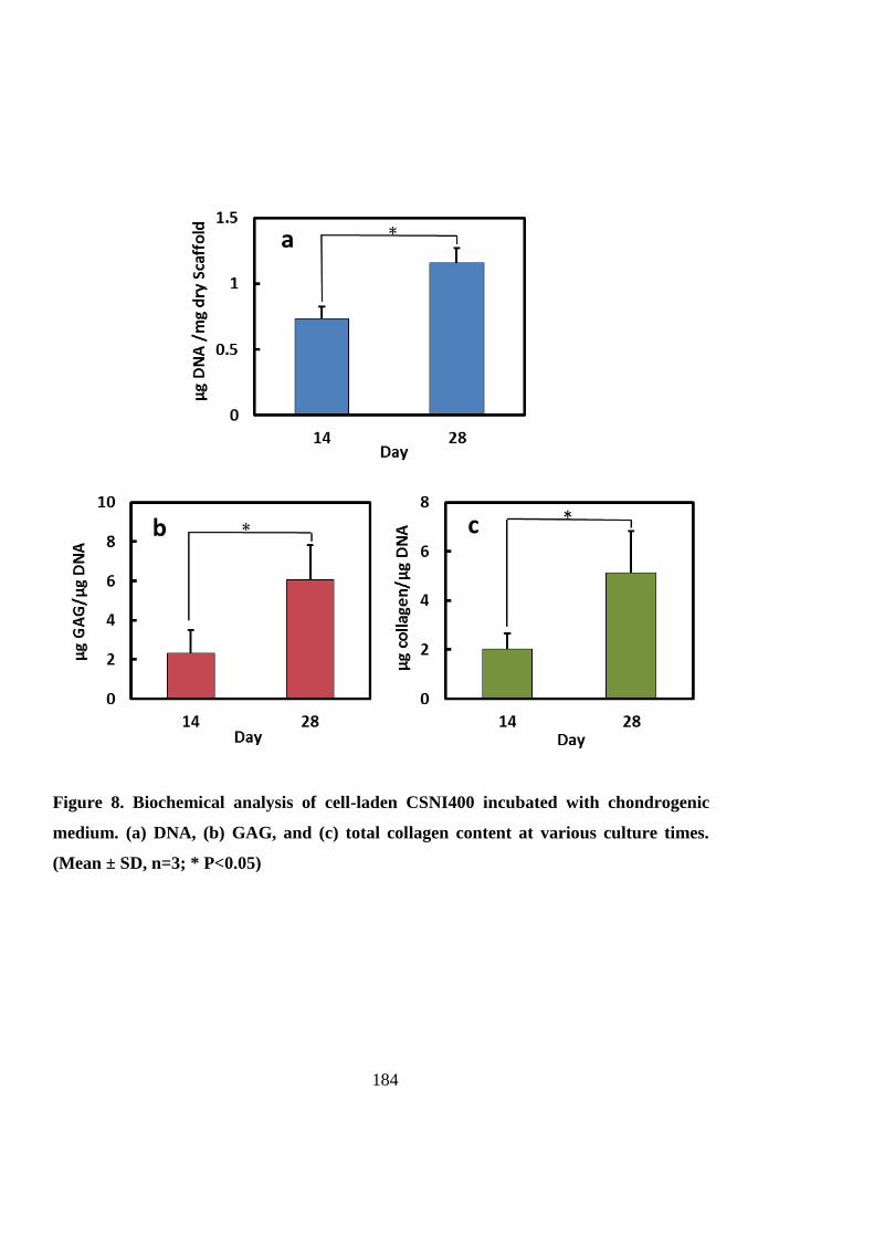
184
Figure 8. Biochemical analysis of cell-laden CSNI400 incubated with chondrogenic
medium. (a) DNA, (b) GAG, and (c) total collagen content at various culture times.
(Mean ± SD, n=3; * P<0.05)

185
Various chitosan-based scaffolds have been investigated for cartilage tissue engineering by
other researchers. For example, gene expression analysis of chitosan/poly(butylene
terephthalate adipate) blend showed less than 20% increase in aggrecan accumulation
during the same culture time (53). In another study, MSCs were cultured in a hybrid
scaffold composed of chitosan/β-glycerophosphate solution and demineralized bone
matrix. During 11 days of culture, almost 2.0 and 2.5 folds of increase in GAG and
collagen type II contents of ECM were reported, while no significant change was seen in
the amount of GAG in case of chitosan alone matrix during the same time. Although the
collagen type II content showed around 2.0 folds of increase (54). These results suggest
that CSNI hybrid system shows better or comparable support for chondrogenesis of MSCs.
6.5 Conclusions
In this study, well-defined PNIPAAm/chitosan hybrids were prepared. Delay time before
incubation to gain a well-distribution of cell and PNIPAAm as well as the less PNIPAAm
loss is 6 min for CSNI100 and 9 min for CSNI400. LCST of PNIPAAm is dropped slightly
by hybridization with chitosan, while still remains in desirable range. CSNI400 have 1.5
folds greater pore volume than CSNI100. Hybrid scaffolds show higher swelling ratio than
chitosan-only scaffolds, and swelling ratio of CSNI400 is also higher than CSNI100. SEM
images indicate that the interconnected porous structure of chitosan was preserved. The
number of mesenchymal stem cells (MSCs) increased 58% and 108 % in comparison with
chitosan scaffold in CSNI100 and CSNI400, respectively after seven days incubation in
growth medium. Glycosaminoglycan and total collagen contents increased 2.6 and 2.5
folds after 28 days culture in chondrogenic medium. Therefore, we examined the
hypothesis that a hybrid matrix composed of a soft PNIPAAm gel with controlled
molecular weight (which can improve the cell compatibility of the structure) and a chitosan
porous scaffold can support stem cell culture. These results suggest that hybrid scaffolds of
chitosan and PNIPAAm with degree of polymerization of 400 are promising matrices for
3D stem cell culture and cartilage tissue engineering.

186
6.6 Acknowledgements
AM would like to acknowledge the Adelaide Scholarship International of The University
of Adelaide. HZ thanks The MAWA Trust and the 111 Project (B12034).
187
6.7 References
1. Keeney M, Lai JH, Yang F. Recent progress in cartilage tissue engineering. Current
opinion in biotechnology. 2011;22(5):734-40.
2. Hunziker E. Articular cartilage repair: basic science and clinical progress. A review
of the current status and prospects. Osteoarthritis and cartilage. 2002;10(6):432-63.
3. Van Vlierberghe S, Dubruel P, Schacht E. Biopolymer-Based Hydrogels As
Scaffolds for Tissue Engineering Applications: A Review. Biomacromolecules. 2011
2011/05/09;12(5):1387-408.
4. Di Martino A, Sittinger M, Risbud MV. Chitosan: A versatile biopolymer for
orthopaedic tissue-engineering. Biomaterials. 2005 10//;26(30):5983-90.
5. Cho JH, Kim S-H, Park KD, Jung MC, Yang WI, Han SW, et al. Chondrogenic
differentiation of human mesenchymal stem cells using a thermoresponsive poly (N-
isopropylacrylamide) and water-soluble chitosan copolymer. Biomaterials.
2004;25(26):5743-51.
6. Chen JP, Cheng TH. Thermo‐Responsive Chitosan‐graft‐poly
(N‐isopropylacrylamide) Injectable Hydrogel for Cultivation of Chondrocytes and
Meniscus Cells. Macromolecular Bioscience. 2006;6(12):1026-39.
7. Fedorovich NE, Alblas J, de Wijn JR, Hennink WE, Verbout AJ, Dhert WJ.
Hydrogels as extracellular matrices for skeletal tissue engineering: state-of-the-art and
novel application in organ printing. Tissue engineering. 2007;13(8):1905-25.
8. Kim I-Y, Seo S-J, Moon H-S, Yoo M-K, Park I-Y, Kim B-C, et al. Chitosan and its
derivatives for tissue engineering applications. Biotechnology advances. 2008;26(1):1-21.
9. Rzaev ZM, Dincer S, Pişkin E. Functional copolymers of< i> N</i>-
isopropylacrylamide for bioengineering applications. Progress in Polymer Science.
2007;32(5):534-95.
10. Kim SY, Cho SM, Lee YM, Kim SJ. Thermo‐and pH‐responsive behaviors of graft
copolymer and blend based on chitosan and N‐isopropylacrylamide. Journal of Applied
Polymer Science. 2000;78(7):1381-91.

188
11. Lee WF, Chen YJ. Studies on preparation and swelling properties of the
N‐isopropylacrylamide/chitosan semi‐IPN and IPN hydrogels. Journal of Applied Polymer
Science. 2001;82(10):2487-96.
12. Chen X, Song H, Fang T, Bai J, Xiong J, Ying H. Preparation, characterization, and
drug‐release properties of pH/temperature‐responsive poly
(N‐isopropylacrylamide)/chitosan semi‐IPN hydrogel particles. Journal of Applied
Polymer Science. 2010;116(3):1342-7.
13. da Silva RM, López‐Pérez PM, Elvira C, Mano JF, Román JS, Reis RL. Poly
(N‐isopropylacrylamide) surface‐grafted chitosan membranes as a new substrate for cell
sheet engineering and manipulation. Biotechnology and Bioengineering.
2008;101(6):1321-31.
14. Wang J, Chen L, Zhao Y, Guo G, Zhang R. Cell adhesion and accelerated
detachment on the surface of temperature-sensitive chitosan and poly (N-
isopropylacrylamide) hydrogels. Journal of Materials Science: Materials in Medicine.
2009;20(2):583-90.
15. Don TM, Chou SC, Cheng LP, Tai HY. Cellular compatibility of copolymer
hydrogels based on site‐selectively‐modified chitosan with poly (N‐isopropyl acrylamide).
Journal of Applied Polymer Science. 2011;120(1):1-12.
16. Lee SB, Ha DI, Cho SK, Kim SJ, Lee YM. Temperature/pH‐sensitive comb‐type
graft hydrogels composed of chitosan and poly (N‐isopropylacrylamide). Journal of
applied polymer science. 2004;92(4):2612-20.
17. Don T-M, Chen H-R. Synthesis and characterization of AB-crosslinked graft
copolymers based on maleilated chitosan and N-isopropylacrylamide. Carbohydrate
Polymers. 2005;61(3):334-47.
18. Chuang CY, Don TM, Chiu WY. Preparation of environmental-responsive
chitosan-based nanoparticles by self-assembly method. Carbohydrate Polymers.
2011;84(2):765-9.
19. Sanoj Rejinold N, Sreerekha P, Chennazhi K, Nair S, Jayakumar R. Biocompatible,
biodegradable and thermo-sensitive chitosan-g-poly (N-isopropylacrylamide) nanocarrier

189
for curcumin drug delivery. International Journal of Biological Macromolecules.
2011;49(2):161-72.
20. Sundaresan V, Menon JU, Rahimi M, Nguyen KT, Wadajkar AS. Dual-responsive
polymer-coated iron oxide nanoparticles for drug delivery and imaging applications.
International journal of pharmaceutics. 2014;466(1):1-7.
21. Gui R, Wang Y, Sun J. Embedding fluorescent mesoporous silica nanoparticles
into biocompatible nanogels for tumor cell imaging and thermo/pH-sensitive in vitro drug
release. Colloids and Surfaces B: Biointerfaces. 2014;116:518-25.
22. Wang Y, Wang J, Ge L, Liu Q, Jiang L, Zhu J, et al. Synthesis, properties and
self‐assembly of intelligent core‐shell nanoparticles based on chitosan with different
molecular weight and N‐isopropylacrylamide. Journal of applied polymer science.
2013;127(5):3749-59.
23. Lee J, Jung M, Park H, Park K, Ryu G. Synthesis and characterization of
thermoresponsive chitosan copolymer as a novel biomaterial. Journal of Biomaterials
Science, Polymer Edition. 2004;15(8):1065-79.
24. Cao Y, Zhang C, Shen W, Cheng Z, Yu LL, Ping Q. Poly (N-isopropylacrylamide)
– chitosan as thermoresponsive in situ gel-forming system for ocular drug delivery. Journal
of Controlled Release. 2007;120(3):186-94.
25. Recillas M, Silva LL, Peniche C, Goycoolea FM, Rinaudo M, Argu elles-Monal
WM. Thermoresponsive behavior of chitosan-g-N-isopropylacrylamide copolymer
solutions. Biomacromolecules. 2009;10(6):1633-41.
26. Chen C, Liu M, Gao C, Lü S, Chen J, Yu X, et al. A convenient way to synthesize
comb-shaped chitosan-graft-poly (N-isopropylacrylamide) copolymer. Carbohydrate
polymers. 2013;92(1):621-8.
27. Tong Z, Zeng F, Zheng X, Sato T. Inverse molecular weight dependence of cloud
points for aqueous poly (N-isopropylacrylamide) solutions. Macromolecules.
1999;32(13):4488-90.

190
28. Mellati A, Dai S, Bi J, Jin B, Zhang H. A biodegradable thermoresponsive
hydrogel with tuneable properties for mimicking three-dimensional microenvironments of
stem cells. RSC Adv. 2014;4(109):63951-61.
29. Zhu PW, Napper DH. Interfacial coil-to-globule transitions: the effects of
molecular weight. Colloids and Surfaces A: Physicochemical and Engineering Aspects.
1996;113(1–2):145-53.
30. Barrett EP, Joyner LG, Halenda PP. The determination of pore volume and area
distributions in porous substances. I. computations from nitrogen isotherms. Journal of the
American Chemical Society. 1951 1951/01/01;73(1):373-80.
31. Brunauer S, Emmett PH, Teller E. Adsorption of gases in multimolecular layers.
Journal of the American Chemical Society. 1938 1938/02/01;60(2):309-19.
32. Zhang J, Chu L-Y, Li Y-K, Lee YM. Dual thermo- and pH-sensitive poly(N-
isopropylacrylamide-co-acrylic acid) hydrogels with rapid response behaviors. Polymer.
2007 3/8/;48(6):1718-28.
33. Hwang NS, Varghese S, Elisseeff J. Cartilage tissue engineering. Stem Cell
Assays: Springer; 2007. p. 351-73.
34. Hoemann CD. Molecular and biochemical assays of cartilage components.
Cartilage and osteoarthritis: Springer; 2004. p. 127-56.
35. Masci G, Giacomelli L, Crescenzi V. Atom Transfer Radical Polymerization of
N‐Isopropylacrylamide. Macromolecular rapid communications. 2004;25(4):559-64.
36. Madihally SV, Matthew HW. Porous chitosan scaffolds for tissue engineering.
Biomaterials. 1999;20(12):1133-42.
37. Solchaga LA, Penick K, Porter JD, Goldberg VM, Caplan AI, Welter JF. FGF‐2
enhances the mitotic and chondrogenic potentials of human adult bone marrow‐derived
mesenchymal stem cells. Journal of cellular physiology. 2005;203(2):398-409.
38. Don T-M, Chen H-R. Synthesis and characterization of AB-crosslinked graft
copolymers based on maleilated chitosan and< i> N</i>-isopropylacrylamide.
Carbohydrate polymers. 2005;61(3):334-47.
191
39. Gilding D, Reed A. Biodegradable polymers for use in surgery—polyglycolic/poly
(actic acid) homo-and copolymers: 1. Polymer. 1979;20(12):1459-64.
40. Lesage de la Haye J, Pontes da Costa A, Pembouong G, Ruhlmann L, Hasenknopf
B, Lacôte E, et al. Study of the temperature-induced aggregation of polyoxometalate-
poly(N,N-diethylacrylamide) hybrids in water. Polymer. 2015;57(0):173-82.
41. Park JH, Lee YH, Oh SG. Preparation of Thermoresponsive PNIPAm‐Grafted
Mesoporous Silica Particles. Macromolecular Chemistry and Physics. 2007;208(22):2419-
27.
42. Xia Y, Yin X, Burke NAD, Stöver HDH. Thermal Response of Narrow-Disperse
Poly(N-isopropylacrylamide) Prepared by Atom Transfer Radical Polymerization.
Macromolecules. 2005 2005/07/01;38(14):5937-43.
43. Radhakumary C, Antonty M, Sreenivasan K. Drug loaded thermoresponsive and
cytocompatible chitosan based hydrogel as a potential wound dressing. Carbohydrate
polymers. 2011;83(2):705-13.
44. Sing KSW, Everett DH, Haul RAW, Moscou L, Pierotti RA, Rouquerol J, et al.
Reporting physisorption data for gas/solid systems with special reference to the
determination of surface area and porosity. Pure and Applied Chemistry. 1985;57(4):603.
45. Rouquerol F, Rouquerol J, Sing K. Adsorption by powders and porous solids
London: Academic Press; 1999.
46. Rinki K, Dutta P. Chitosan Based Scaffolds by lyophilization and sc. CO2 assisted
methods for tissue engineering applications. Journal of Macromolecular Science, Part A:
Pure and Applied Chemistry. 2010;47(5):429-34.
47. Kumari R, Dutta P. Physicochemical and biological activity study of genipin-
crosslinked chitosan scaffolds prepared by using supercritical carbon dioxide for tissue
engineering applications. International journal of biological macromolecules.
2010;46(2):261-6.
48. Jones JR, Ehrenfried LM, Hench LL. Optimising bioactive glass scaffolds for bone
tissue engineering. Biomaterials. 2006;27(7):964-73.
49. Chen VJ, Ma PX. Nano-fibrous poly(l-lactic acid) scaffolds with interconnected
spherical macropores. Biomaterials. 2004;25(11):2065-73.

192
50. Guilak F, Cohen DM, Estes BT, Gimble JM, Liedtke W, Chen CS. Control of Stem
Cell Fate by Physical Interactions with the Extracellular Matrix. Cell Stem Cell.
2009;5(1):17-26.
51. Zhang H, Dai S, Bi J, Liu K-K. Biomimetic three-dimensional microenvironment
for controlling stem cell fate. Interface Focus. 2011;1(5):792-803.
52. Lund AW, Yener B, Stegemann JP, Plopper GE. The natural and engineered 3D
microenvironment as a regulatory cue during stem cell fate determination. Tissue
Engineering Part B: Reviews. 2009;15(3):371-80.
53. Alves da Silva ML, Martins A, Costa‐Pinto A, Correlo V, Sol P, Bhattacharya M,
et al. Chondrogenic differentiation of human bone marrow mesenchymal stem cells in
chitosan‐based scaffolds using a flow‐perfusion bioreactor. Journal of tissue engineering
and regenerative medicine. 2011;5(9):722-32.
54. Huang H, Zhang X, Hu X, Dai L, Zhu J, Man Z, et al. Directing chondrogenic
differentiation of mesenchymal stem cells with a solid-supported chitosan thermogel for
cartilage tissue engineering. Biomedical Materials. 2014;9(3):035008.

193
CHAPTER SEVEN
Conclusions and future directions 7.

194
195
To be able to regenerate functional articular cartilage, my PhD study was focused on
engineering of well-defined matrices as biomimetic 3D microenvironment for stem cells.
Two forms of chitosan matrices were prepared: chitosan-g-poly(N-isopropylacrylamide)
(CS-g-PNIPAAm) copolymers and chitosan/well-defined PNIPAAm (CSNI) hybrids.
Mesenchymal stem cells (MSCs) were cultivated in two matrices to evaluate the
proliferation performance and then they were differentiated in the chondrogenic
differentiation media for the cartilage regeneration. The main conclusions are summarized
below:
1- The CS-g-PNIPAAm copolymer hydrogel can provide an appropriate
microenvironment for 3D cultivation of MSCs. I have optimized various
polymerization conditions including acid concentration in polymerisation media,
monomer concentration in the feed, and reaction temperature to obtain the best
hydrogel for MSC culture with desired physical and mechanical properties. The
advantage of this system is to proliferate MSC in the 3D porous networks. After
MSC proliferation, MSCs can be recovered by separating cells from the polymer
solution at room temperature using the sol-gel thermo-reversible property of the
CS-g-PNIPAAm copolymer.
2- The CS-g-PNIPAAm hydrogel with manipulated properties can be micropatterned
for regenerating the superficial zone and the middle zone of articular cartilage. The
CS-g-PNIPAAm hydrogel has been demonstrated to support the embedded MSCs
differentiated into chondrocytes in 3D through extracellular matrix component
(glycosaminoglycan (GAG), total collagen and collagen type II) analysis. GAG and
total collagen contents (per DNA) increase 1.6 and 1.4 folds from day 14 to day 28
in chondrogenic medium. Histological and immunohistochemical stainings also
confirm the increasing accumulation of GAG and collagen type II. Collagen type II
was typically used as an indicator for cartilage produced in vitro. The detailed
examination of the collagen forms that mimic body structure will be carried out in
future work. The cell-laden hydrogel micropatterned in 50-100 µm constructs can
align cells along the microchannel horizontal axis. 75 % of cells are oriented with
an aspect ratio of 2.0 in 50 µm wide microconstructs at day 5. The cell shape and

196
alignment in the constructs is very similar to the superficial zone of chondrocytes
of the native cartilage. Meanwhile, cells in the microchannel with the gap above
150 µm are randomly distributed (12% alignment and aspect ratio of 1.2, in
unpatterned constructs), which can be used to mimic the middle zone of the
cartilage tissue.
3- The CSNI hybrid matrices composed of chitosan scaffolds and well-defined
PNIPAAm with a degree of polymerization of 400 (CSNI400) can provide a
supporting platform for 3D stem cell culture and cartilage tissue engineering. Well-
defined and narrow-dispersed molecular weights of PNIPAAm have been
synthesized through atom transfer radical polymerization (ATRP). The cytotoxicity
of PNIPAAm is molecular weight dependent, and varies with the PNIPAAm chain
length. The PNIPAAm hydrogel may be detrimental to stem cells when the cells
are covered with a thick layer of gel, and this layer may become a barrier for
nutrient or oxygen delivery to cells. However, cells are mixed with PNIPAAm
solution and the solution is incorporated in the voids of the chitosan scaffolds. The
phase separation of PNIPAAm at 37 oC leads to a hybrid matrix for MSCs. After
seven days incubation of CSNI400 in growth medium, viable cell number in cell-
laden hybrid is 108% higher than chitosan. GAG and total collagen contents (per
DNA) increase 2.6 and 2.5 folds from day 14 to day 28 in chondrogenic medium.
In conclusion, 3D microenvironment for stem cells was created and refined through
manipulation of matrices in order to enhance cell proliferation and chondrogenic
differentiation. The results revealed that graft copolymer of chitosan and PNIPAAm with
tailored properties and microengineered architecture is appealing for zonal cartilage tissue
engineering. The hybrid matrices from chitosan scaffolds with well-defined PNIPAAm
hydrogels promote chondrogenesis, much better than the graft copolymer.
Thermoresponsive hydrogels were explored with controlled physical, mechanical and
chemical properties for cartilage tissue engineering. Chitosan-g-PNIPAAm with random
chain length (not well-defined) and chitosan/well-defined PNIPAAm hybrid were prepared
in this PhD project. Graft copolymerization of chitosan and well-defined PNIPAAm and its

197
interactions with MSCs for chondrogenic differentiation remained to be studied in future.
A novel method to address cartilage spatial organization was also developed using
microengineered CS-g-PNIPAAm. On the other hand, based on the results, CSNI hybrid
is a better choice for chondrogenic differentiation of MSCs than CS-g-PNIPAAm.
Therefore, microengineered CSNI hybrids as well as graft copolymer of chitosan and well-
defined PNIPAAm might be potential follow-up research projects. Stacking the
microengineered constructs to form a macroscale 3D cartilage tissue and evaluation of the
engineered cartilage needs to be further investigated. In addition, implantation of the
engineered tissues to assess their actual functionality in vivo is essential for clinical
translation. Pharmacokinetics of PNIPAAm and its exertion from body after degradation of
chitosan backbone needs an additional comprehensive study. More characterization of
well-defined PNIPAAm such as viscosity differences may also help us to improve the
hybrid matrices.

198

199
APPENDIX: Published papers in their Journal styles

Mellati, A., Dai, S., Bi, J., Jin, B. & Zhang, H. (2014) A biodegradable thermosensitive hydrogel with tuneable properties for mimicking three dimensional microenvironments of stem cells. RSC Advances, vol 4, pp. 63951-63961
NOTE:
This publication is included after page 199 in the print copy of the thesis held in the University of Adelaide Library.
It is also available online to authorised users at:
http://dx.doi.org/10.1039/c4ra12215a

Shen, Z., Mellati, A., Bi, J., Zhang, H. & Dai, S. (2014) A thermally responsive cationic nanogel-based platform for three-dimensional cell culture and recovery. RSC Advances, vol 4, pp. 29146-29156
NOTE:
This publication is included after page 199 in the print copy of the thesis held in the University of Adelaide Library.
It is also available online to authorised users at:
http://dx.doi.org/10.1039/c4ra02852j


