THERMOJUNCTIONS - Philips Bound... · 7.69 -4.86 =2.83volts areneeded and this energy ... current...
10
JUNE 1938 ELECTRICAL PHENOMENA IN THE POSITIVE COLUMN AT LOW PRESSURE is more advantageous to bring the atom from the 4.86 volt state, to which it has fallen after emission of the blue line, immediately back again to the 7.69 volt state, than to wait until the atom has returned to the zero state and emitted the ultraviolet line 2537 A. In the first case only 7.69 - 4.86 = 2.83 volts are needed and this energy is radiated entirely in the visible region; in the second case, however, 7.69volts are needed ofwhich only 2.83 volts are transformed into visible light. These cumulative effects are very much favoured in the case of mercury by the fact that 4.86 volts is a "resonance level" and 5.43 volts a so-called "metastabie level". Since line 2537 is a resonance line, it is readily absorbed by' the atoms, in the .zero-state. After about 10- 7 sec emission again takes place, and the energy radiated can then' be ab- sorbed by another atom in the zero state. This process is repeated very' many times before the resonance radiation leaves the tube, so that the concentration of atoms in the 4.86 volt state ID- creases sharply and with it the chance of cumulative excitation from this level to a higher one. For the metastable 5.43 volt level also the chance of cumulative excitation is large. If the atom has been brought into the 5.43 volt level by collision with an electron, it cannot easily return directly to the zero state byemission of radiation, it usually does so by means of collision with other atoms or elec- trons. The life of such a metastable atom, about 10-4 sec., is much longer than that of an atom in an ordinary excited state, so that the chance of cumu- lative excitation is thereby increased. In the low pressure mercury discharge used. in the blue illuminated advertising signs, concentration of the current therefore is an advantage. In the high pressure mercury lamps this phenomenon is even more stimulated by the compression 'of the dis- .charge to a narrow zone near the axis, .' Fig. 11 gives a schematic survey of the various processes here discussed which occur in the positive column. THERMOJUNCTIONS by J. W. L. KÖHLER., 621.317.7.082.62 The construction and action of thermojunctions are discussed in this article. A detailed accoun~is given of the factors which affect the sensitivity and the characteristic of such junctions. The choice of the meter movement and the classification of thermojunctions are explained. Finally a survey is given of Philips thermojunctions. Introduction article we shall discuss the last type of instruments. When an alternating current ofvery low frequency In thermal instruments use is made of the heat is sent through a suspended coil galvanometer which development in a resistance, when a current passes has its zero point in the middle of the scale, the through it. Etis obvious therefore that the direction meter indicates the current at every moment; the of the current can have no influence on the deflection pointer moves back and forth with the frequency of the meter. The heat developed can be used in of the alternating current. If the frequency is raised, various ways: . then after a moment of resonance the deflection i). The thermal expansion of the resistance fila- becomes smaller and' the pointer finally remains ment can be indicated by a pointer in some . practically still due to the fact that the moving way or other . . system of the 'meter cannot follow t the high fre- b) The heat developed can be used to heat a quency. A .suspended coil galvanometer is therefore quantity of gas whose increase in volume is not suitable for measuring alternating currents. indicated by a drop of liquid in a capillary. Such currents can only be measured with an c) The change in resistance of a filament forming .Instrument whose deflections are always in one, part of a Wheatstone bridge may .be direction, no matter what the direction of the measured. current, and whose pointer can therefore adjust d) The heating of the filament can be measured itself to a definite average deflection. This condition with a thermocouple connected to a direct is fulfilled by dynamometers, soft-iron meters, current meter. rectifying meters and thermal instruments. In this We shall treat the last method in detail, 165
Transcript of THERMOJUNCTIONS - Philips Bound... · 7.69 -4.86 =2.83volts areneeded and this energy ... current...
JUNE 1938 ELECTRICAL PHENOMENA IN THE POSITIVE COLUMN AT LOW PRESSURE
is more advantageous to bring the atom from the4.86 volt state, to which it has fallen after emissionof the blue line, immediately back again to the7.69 volt state, than to wait until the atomhas returned to the zero state and emitted theultraviolet line 2537 A. In the first case only7.69 - 4.86 = 2.83 volts are needed and this energyis radiated entirely in the visible region; in thesecond case, however, 7.69 volts are needed ofwhichonly 2.83 volts are transformed into visible light.These cumulative effects are very much favoured
in the case of mercury by the fact that 4.86 voltsis a "resonance level" and 5.43 volts a so-called"metastabie level". Since line 2537 is a resonanceline, it is readily absorbed by' the atoms, in the. zero-state. After about 10-7 sec emission again takesplace, and the energy radiated can then' be ab-sorbed by another atom in the zero state. Thisprocess is repeated very' many times before theresonance radiation leaves the tube, so that theconcentration of atoms in the 4.86 volt state ID-
creases sharply and with it the chance of cumulativeexcitation from this level to a higher one. For themetastable 5.43 volt level also the chance ofcumulative excitation is large. If the atom has beenbrought into the 5.43 volt level by collision withan electron, it cannot easily return directly to thezero state byemission of radiation, it usually doesso by means of collision with other atoms or elec-trons. The life of such a metastable atom, about10-4 sec., is much longer than that of an atom in anordinary excited state, so that the chance of cumu-lative excitation is thereby increased. In the lowpressure mercury discharge used. in the blueilluminated advertising signs, concentration of thecurrent therefore is an advantage. In the highpressure mercury lamps this phenomenon is evenmore stimulated by the compression 'of the dis-.charge to a narrow zone near the axis, .'
Fig. 11 gives a schematic survey of the variousprocesses here discussed which occur in the positivecolumn.
THERMOJUNCTIONS
by J. W. L. KÖHLER., 621.317.7.082.62
The construction and action of thermojunctions are discussed in this article. A detailedaccoun~is given of the factors which affect the sensitivity and the characteristic of suchjunctions. The choice of the meter movement and the classification of thermojunctionsare explained. Finally a survey is given of Philips thermojunctions.
Introduction article we shall discuss the last type of instruments.When an alternating current of very low frequency In thermal instruments use is made of the heat
is sent through a suspended coil galvanometer which development in a resistance, when a current passeshas its zero point in the middle of the scale, the through it. Etis obvious therefore that the directionmeter indicates the current at every moment; the of the current can have no influence on the deflectionpointer moves back and forth with the frequency of the meter. The heat developed can be used inof the alternating current. If the frequency is raised, various ways: .then after a moment of resonance the deflection i). The thermal expansion of the resistance fila-becomes smaller and' the pointer finally remains ment can be indicated by a pointer in some
. practically still due to the fact that the moving way or other .. system of the 'meter cannot follow t the high fre- b) The heat developed can be used to heat aquency. A .suspended coil galvanometer is therefore quantity of gas whose increase in volume isnot suitable for measuring alternating currents. indicated by a drop of liquid in a capillary.Such currents can only be measured with an c) The change in resistance of a filament forming.Instrument whose deflections are always in one, part of a Wheatstone bridge may .bedirection, no matter what the direction of the measured.current, and whose pointer can therefore adjust d) The heating of the filament can be measureditself to a definite average deflection. This condition with a thermocouple connected to a directis fulfilled by dynamometers, soft-iron meters, current meter.rectifying meters and thermal instruments. In this We shall treat the last method in detail,
165

166 PHILIPS TECHNICAL REVIEW Vol. 3, No. 6
Construction and action of thermo-electric ammeters
KIe m en cic was the first to construct a measuringinstrument on this principle. The'instrument consistsof two wires of diffe~ent materials which form athermo-electric couple, The two wires are woundtogether, knotted together or welded together atthe middle (seejig. 1). The current to be measured
Fig. 1. Kl emenë ië 's thermocouple. The wire ofonemetalis fastened to terminals 1 and 4, that of the other metal toterminals 2 and3.The wires are joinedin the middle electricallyin some way. The current to be measured passes throughalong the terminals 1 and 2, the galvanometer is connectedbetween 3 and 4.
is supplied to the terminals 1 and. 2; the wiresbèè~me warm" at the' middle due to the heatdevelopment; this causes a thermal electromotiveforce between the terminals 3 and 4. This voltagecan be measured by' connecting a sensitive meterto the terminals.
There are various objections to this constructionwhich will appear later. Fig.2 gives a sketch of
Fig. 2. Modern thermocouple. Between terminals 1 and 2a filament is stretched, and between3 and 4 there is a thermo-couple whosejunction is fastened to the fila~ent.
a modern thermo-electric ammeter from which it.'may be seen that the principle is the same as thatof the original. A filament is stretched between1 and 2. Midway between the terminals a thermo-couple is fastened -to the filament with its junctionon or close to the filament. The ends of the thermo-couple are fastened to the terminals 3 and 4, 'between which the direct current ammeter isconnected. The whole is often placed in an evacuatedbulb. When this is done there is no loss of heatby convection, and the sensitivity of the instrumentis increased. In certain types the thermocouple iselectrically connected with the filament, in othersit is insulated from ,the filament. This constructionis not so simple as the original one, but it hascertain advantages. One of these is immediately. obvious. 'The thermo-electric properties of thefilament material need not be considered, so rhatthe choice becomes muclî greater.
We shall now discuss the action' of'.the thermo-
electric ammeter. If. a current i is sent throughthe filament with the resistance Rg, an amountof heat equal to i2Rgt will he developed in thefilament. ,The temperature of the filament will_'thereby be raised; the heat is lost by conductionover the terminals, and by conversion intoelectrical energy through the thermocouple andby radiation. If the amount of heat which is givenup is proportional to the increase in temperature,the latter will be proportional to the heat developed,i;e. to i2• The same is true of the temperatureof the junction of the thermocouple. If the thermalelectromotive force is proportional to the tempera-ture difference, it will also be proportional to i2,and the same is true of the current in the circuitcomprising thermocouple and galvanometer, whichcurrent' is proportional to the thermal electro-motive force. The deflection ofthe galvanom-eter is therefore proportional to the squareof the current in the filament.The ratio between the current through the
galvanometer and the current through the filamentis called the characteristic of the thermocouple.Here the characteristic ' is quadratic. Therefore,with a meter having a quadratic scale division,after calibration of" one point on the scale, theprimary current may be read off directly. A meterwith a linear scale can àlso be used, the readingis then proportional to i2,' i..e. to the cnergywhich can be developed by the prim~ry currentin a resistance; this method of measurement hasmany practic~l applications.
Mathematical analysis
We shall give a brief account of the mathema-tical analysis of the action of' the thermo-ammeter. We shall first consider 'the filamentalone without the thermocouple, The followingdifferential. equation holds for the teinperatureincrease in.a straight wire stretched between twopoints and heated by a current:
d21' au , Ai2(!- - - • + - = 0 . (1)dx2 Aq Aq2
- I
Where:x the coordinate of length of the wire from the
middle in centimetres,r the tempera~ure difference with respect to the
surroundings at the point x in degrees centi-grade,
u. the circumference of the wire in centimetres,q the area of the cross section of the wire in square
centimetres,i the electric current in amperes,

JUNE 1938 THERMOJUNCTIONS 167
A the electrical equivalent of heat, 0.2388 caloriesper watt second,
e the ,specific resistance of the wire in ohm centi-metres,
a the heat radiation in calories per centimetresecond,
A 'the specific conductivity for heat, in cal/cmsec. degr. C.
Equation (1) can be derived as follows. Consider a lengthdx of the wire; at the ends of this element the temperature
, (dor) ( d.) .gradients are - and - . By heat conduction' thereforedXl dx2
the following amount of energy is supplied to the element:
.A~ [( :) 1- ( :) J = Aq :: dx .
Ai2e 'An amount of heat -- dx is developed in the element by
qthe current ·i. If the element is situated in a vacuum it losesenergy to the surroundings only by radiation; the amountof this radiation is u a • dx, where it is assumed that theradiation is proportional to the temperature difference, whichis permissible when the' increases in temperature are small(see below for more detailed explanation), In the stationary .state the energy supplied must equal the energy given off,and therefore
d2• Ai2e .Aq-dx + ~- dx = uo r de,
dx2 q
from which (1) f1llows.In this derivation it is therefore assumed that e, A and aare independent of the temperature; we shall see later whatchanges are necessary when this condition is no longer satisfied,
If the limiting condition is introduced that theincrease. of temperature at the terminals is> zero
, . (x = ± l/2.), then the equation has the followingsolution:
Ai2eï:=--.
auq
" ~ucosh x -., A1":"" q
l~ucosh- -2 Aq
(cosh a' is the, hyperbolic cosine of a, i.e. the\ abreviated notation ofl/2.(ea + e-à); the expression.hyperbolic tangent which occurs later' stands forea - e-a·
, ). In fig. 3a this increase of temperature isea + e-adrawn for' different points of the filament.
At the middle the increase in temperature
A i2e lt=-- 1auq
(t) is:
1 l Ai2e { 1 ~=- 1- . (3)l~u . auq cosh K .
cosh- -2 Aq
~ ~ = 1V;; for round wireswhere K
240T't'
t200160
.
-I-.",
/;I" <,
N./ "'-J "'-,I - r-, -~ \/"" V;;/ "~'
I{'_ '\
,120
, 80
40
à0.5 0,4 0,3 G,2
x-T~0,1 0 0,1 02 0,3 0,4 os
x'~+T.e66S'
Fig. 3) a) Temperature of a stretched wire through whichcurrent is flowing,Temperature of the same wire when a thermo-couple is fastened at its middle point.
. b)
with the diameter d. The increase of t~mperatureis therefore actually proportional to i2• When K issmall (this is usually the case in practical appliéationsas we, shall see later), we may write: .
cosh K = 1+ '1(2/2,
and (3) becomes:
A i2 ell----=8 .q Aq
Ai28 e,»; (3a)
(2)
In this expression Rg is the electrical and Rw theheat resistance of the filament. In (3~) the radiationconstant 6 no longer occurs due to the approxima-tion. This fact will be found later to be very im-portant.We, shall now pass on to the cas~where a 'thermo-
couple, is fastened to the middle of the filament.This can be described in good. approximation bycalculating that a quantity of heat M is removed'at the middle of the filament per second and per'degree increase of temperature. The differentialequation then becomes more' complicated; we shall
, only give the result for the increase in temperaturetM at the middle of the wire:
.11- --=--=Ai2e cosh K
«v« M tghK1+ ,--;;--
2}aAuq
t. (4).
MtghK1+ ----:==
2VaAuq
The increase of temperature is therefore greater,tanhK
the smaller M. The factor takes account of, ... 'YaÀuq .
the fact that the heat lost flows to the middleof the :filament from parts lying near the middle.For small values of K the following holds:

168 PHILIPS TECHNICAL REVIEW Vol. 3, No. 6
In this case also the increase in temperature isproportional to i2• The influence of the heat con-duction is less than in (3a). This is clear enough.In the first case a great increase in temperaturecould be attained by a high heat resistance of thefilament; the supply of heat to the middle of thefilament has now become an important factor. Infig. 3b we gïve an idea of the variation of temperaturealong the filament; the middle no longer has thehighest temperature. . .
Finally the value of M must be expressed interms of the dimensions and constants of thethermocouple. An analogous differential equationis valid here, but with different limiting conditions ..The solution is the following:
M _ YGlÀlUlql1- ,
tghKl .
where the subscript 1 indicates that the valuesare for one of the wires of the thermocouple.The same formula with the subscript 2 holdsfor the other wire; the length of the wires is
4 12 11yGlUl- and -; Kl = - -- ...The loss ofheat through2 2 . 2 Àl ql .the whole thermocouple is:
M = MI + M2•
At small values Of Kl (5) becomes:
M1= 2Àlql
·'4Ifwe introduce this value ofM into (4) the equationbecomes:
A i2 (! 12
8Àq2tM= --------~~~--------
1 + -2~-q~_À14_ql+ -À2-Z2
q_2~
The temperature of the middle of the filament is thereforenow expressed 'in the dimensions and constants of the wiresof the thermo-couple.Let us first consider the numerator of (4b). Leaving out
the constants of the material we may, write:
'q2t ~ _~_"_'i2R2M . q2 s '
The dimensions of the filament occur' only in the form I/q;filaments, therefore, with different dimensions but with thesame resistance undergo the same increase in temperature
(4a)
'(Sa)
(5)
with a given current. The voltage drop caused by the filament,iRg = V, is not dependent on the dimènsions of the filament.lf a definite rise in temperature must be attained with differentcurrents, the resist~nce of' the filament must be inverselyproportional to the current. The energy necessary for a giventemperature increase, V2/Rg' is inversely proportional to theresistance, and therefore proportional to the current; thermo-ammeters for small currents, therefore, possess a greaterenergy sensitivity than those for heavy currents.The foregoing remains true when the second term in the
denominator is small with respect to one; this is the casewhen there is only a slight loss of heat through the thermo-couple, or when 1/2 Î. q is small. The latter is always thecase with. thermc-ammeters for larger currents (i I/q mustalways he constant). If the second term may not beneglected, which is the case with thermc-ammeters forlow currents, the sensitivity to energy is smaller. A smallheat loss through the thermocouple is therefore favourablein such a case. Since ,.1,1 and ,.1,2 are usually given (the choiceof material is determined by the thermo-electric properties),this can be achieved by making ql/Il and q2/12 small. The. (!lIl (! I
resistance of the thermo-couple Rc = -2 + -222, however,. ql q2
becomes large as a consequence of. this measure; a limit is'thereby set to the reduction of 1\-f (see later). The dimensionsof the thermocouple occur only in the form q/I, so that wireswith the same electrical resistance cause the same heat loss.o In the above it is always assumed that the radiation maybe neglected; this assumption is the basis of the approximationemploy~d here,
With a given thermoelectric combination theabove considerations are also valid for the thermalelectromotive force E'h. The sensitivity of thethermo-electro~eter is of course proportional tothe thermoelectric force per degree. The currentthrough the galvanometer im is the following,when- Rm is the resistance of the meter:
. E'ht -m- R+ R 'e, m,
(4b)
where Re is the internal resistance of the thermo-couple.
Connection of the measuring instrument to thethermocouple
We may continue with our considerations along. two lines.
a) We may begin with a given thermocouplewith resistance Rc, and ask what meter we mustuse in order to obtain the greatest deflection' with. a definite primary current i. To' answer this wemust calculate the voltage on the. meter:
Em = E'h Rm Em Rm/Re (6)e; + Re Eth Rm/Re + 1
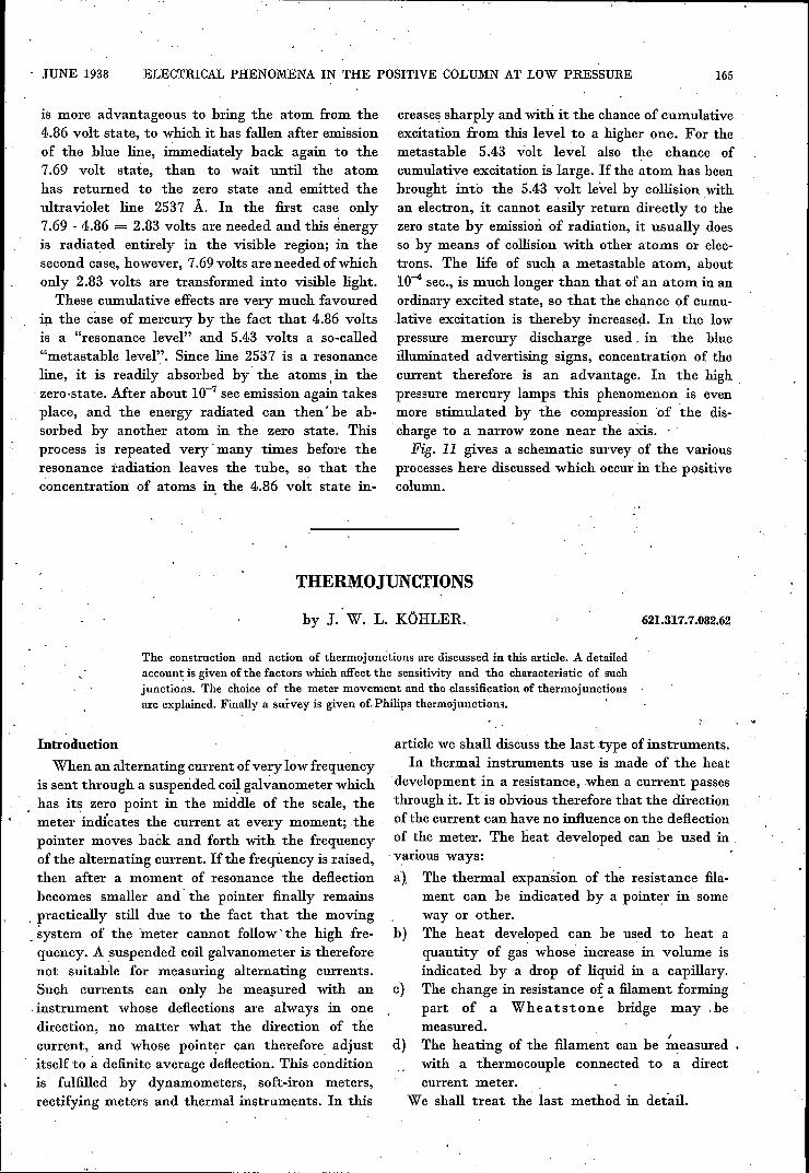
Fig.4 gives a graphic representation of (6). The .l·equirement· is that the sensitivity to voltageof the meter . (i.e. the deflection at a definite'
JUNE 1938 THERMOJUNCTIONS 169
voltage on the. meter) shall be so great that themeter has the desired deflection with the voltagecalculated from (6). When Rm = Re the thermo-
.É!Il..1,2r 1.0
0,
-- ----- -- --r-- 1-- - --
V I--
/.V
4 -I,
I!I1 1
11
0,8
0,2
o'0 f. 2 3 4 5 6
26698
Fig. 4. Drop in terminal voltage of the thermocouple, whencurrent is taken offby the meter. Em/E'h is plotted as a functionof Rm/Re' When Rm = Re ,the most favourable energy transfer.takes place.
couple gives off the greatest amount of energy tothe meter. A meter with this resistance' therefore
, deflectionmay be the least sensitive to energy ( .
energymay be smallest); it is usually also the cheapestmeter. A more sensitive meter may, however, also
, he used.b) We may begin with a given meter, and ask
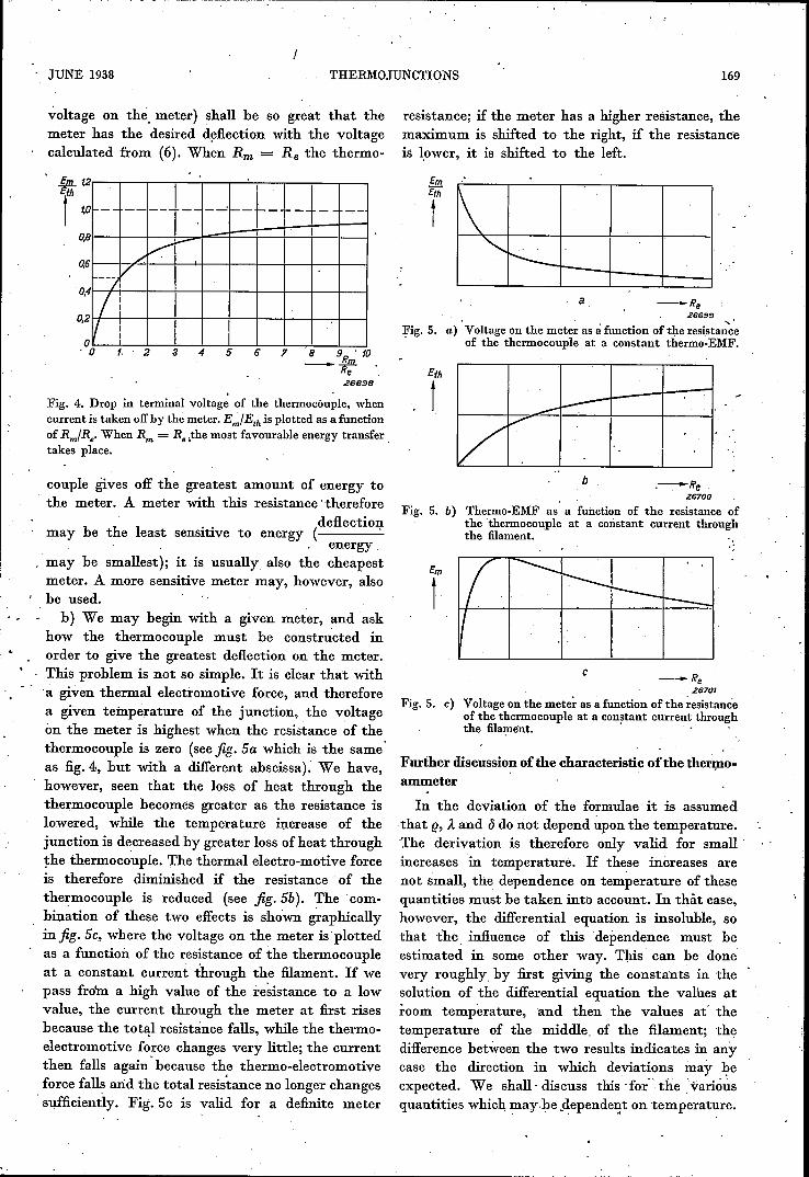
how the thermocouple must be constructed inorder to give the greatest deflection on the meter.This problem is not so simple. It is clear that with'a given thermal electromotive force, and thereforea given teinperature of the junction, the voltageon the meter is highest when the resistance of thethermocouple is zero (see fig. Sa which is the sameas fig.4, but with a different abscissa). We have,however, seen that the loss, of heat through thethermocouple becomes greater as the resistance islowered, while the temperature increase of the 0
junction is decreased by greater loss of heat throughthe thermocouple. The thermal electro-motive forceis therefore diminished if the resistance of thethermocouple is reduced (see fig. Sb). The com-bination of these two effects is shown graphicallyin fig. Se, where the voltage on the meter isplottedas a function of the resistance of the thermocoupleat a constant current through the filament. If wepass from a high value of the resistance to a lowvalue, the current through the meter at fust risesbecause the total resistance falls, while the thermo-electromotive force changes very little; the currentthen falls again' because the thermo-electromotiveforce falls arid the total resistance no longer changessufficiently. Fig. 5c is valid for a definite meter
resistance; if the meter has a higher resistance, themaximum is shifted to the right, if the resistanceis lower, it is shifted to the left.
Em
r 1\'I'--"
l-t--I--a -Re
2GG!}!!
"Fig. 5. a) Voltage on the meter as à function of the resistanceof the thermocouple at a constant thermo-EMF.
Eth
t ,
....-~
-:........
'.b .-Re
2G700. ,
Fig. 5. b) Thermo-EMF as a function of the resistance ofthe 'thermocouple at a constant current throughthe filament.
Em
t
c
Fig. 5. c)
--Re2G701
Voltage on the meter as a function of the resistanceof the thermocouple at a constant current throughthe filament. . .'
Further discussion ofthe characteristic ofthe thermo-ammeter
In the deviation of the formulae it is assumedthat (j, À and ()do not depend upon the temperature.The derivation is therefore only valid for small 0
increases in temperature. If these increases arenot small, the dependence on temperature of thesequantities must be taken into account. In thàt case,however, the differential equation is insoluble, sothat the, influence 'of this 'dependence must heestimated in some other way. 'I'his can he donevery roughly. by first giving the constauts in thesolution of the differential equation the values atroom temperature, and then the values at' thetemperature of the middle, of the filament; thedifference between the two results indicates in anycase the direction in which deviations may J;leexpected. We shall' discuss this' for' the "variousquantities which may.he ,depende~t on temperat~re.

170 PHILIPS TECHNICAL REVIEW Vol. 3, No. 6
, ,
With each individual quantity it will he foundthat the result of its dependence on temperatureis that the characteristic is no longer truly quadratic.In favourable cases the deviations due to the differ-ent quantities may compensate each other.e. The temperature coefficient of the specific
resistance ,has very different values for differentmaterials; it is for example positive and about0.4 per cent per degree eentigrade for copper,platinum and 'iron, and practically zero for con-stantan and manganin. If e is positive the resistanceincreases with increasing current through the wire,so that with a high current relatively too muchenergy is developed. The deflection of the galvano-meter will thus be greater than proportional to the. square of the primary current.
Ä. The temperature coefficient of heat conductivityis much smaller than that of electrical resistance;it is weakly negative for the pure metals andpositive for constantan and manganin. Experiencehas shown' that its înfluence is slight; the reasonfor this lies in the above-mentioned fact that asmall value of Ä 0Ii. the one hand improves the heatinsulation of the filament, and on' the: other handit prevents the conduction of heat to the thermo-couple. A change in Ä therefore will 'in the firstapproximation only influence the variation oftemperature along the filament, but not thetemperature öf the middle. This does not of coursehold for the loss of heat through the thermocouple,which is proportional to the heat conductivity ofthe thermocouple. If the latter has a positivetemperature coefficient the result is that thedeflection increases more slowly' than proportionalto the square of the, current.
(J. The Stefan-Boltzmann law holds for theheat radiation of a black body. According to thisiaw the amount of energy radiated per secondand per square centimetre ~f the body is pro-portional to the fourth power of the absolutetemperature. If thé" radiation takes \ place insurroundings at the temperaturè TO) the radiationis then:
R = S (T4 _ T04) cal'. ,cm2·sec·degree4
If the temperature differences under eonsiderationare not great, this expression may be replaced by:
R = S a (T - To) = S a ~.
The quantity a, however, now depends upon thetemperature difference, and as a second app~oxjma-tion we may write:
a-r = ao (1 + a 1').
The constant a is approximately independent on thetemperature difference, ,and between 200 C and1000 C it is equal to + 0.6 per cent per degreeCentigrade. The dependence. of <5 on températureresults in the fact that the increase in temperature isless than the formula indicates, and therefore thedeflection of the galvanometer changes less thanproportional to the square of the primary current.
In addition e, Ä and (J, the thermo-e.m.f. perdegree, the resistance of the thermocouple andthe heat resistance from the middle of thefilament to the junction of the thermocouple mayalso depend upon the temperature. In many casesthe temperature coefficient of the thermo-e.m.f,may be neglected. The resistance of the thermo- .couple' forms merely' a part of the resistanceof the meter circuit, ·so that its influ~nce may heslight. It is very difficult to make an estima-tion of the heat resistance of the connectionbetween :filament and. thermocouple, and of theway in which this depends upon the temperature;,its influence becomes less according as the heatresistance of the thermocouple is increased. Withpoorly made junctions, however, this influence mayvery well be feIt, so that the connection must be .very carefully made.
From the above discussion it follows that .particularly the radiation can cause great deviationsfrom the quadratic variation of the characteristic.It is therefore desirable to make the radiation asslight as possible. We have seen in the discussionof the expression for -the température at the middleof the filament that this temperature is independentof the dimensions for a given resistance of the:filament. The radiation, however, is 'proportionalto the surface of the wire; to make the radiationsmall therefore the dimensions must be kept small. .At small values of K the radiation constant' (J
no longer occurs in _the formulae. The value of Kis therefore a measure of the influence of radiation.K is proportional to ljfiJ; the energy sensitivityon the other hand is proportional to ljd2•
With constant energy sensitivity (ljd2 = Cl)'therefore; Ct d3/2 must be made as small as possible;d must therefore be small.
The same holds for the dimensions of the thermo-couple. Wires with differe~t dimensions but with 'the same electrical resistance cause the sàme lossof heat; if the dimensions, and therefore the surface,are small, the. radiation has the. least influence.Therefore short thin wires must be usedto, construct thermojunctions with aquadratic characteristic. By this means theheat capacity of the thermo-couple is. decreased
, "
JUNE 1938 THERMOJUNCTIONS 171
at the same time, so that the final deflection ofthe meter is more quickly attained. A limit is setto the reduction of the dimensions, however,because such reduction diminishes the ability towithstand overloads.
Overloading and sensitivity
We have seen t.hat the highest temperature ofthe filament does not occur in the middle of thewire, but somewhere between the middle and theter~als. If the ~urrent through the filament ismade too high, the filament will burn through atthose spots. It is therefore important that theratio' of this maximum temperature to the tem-perature at the middle should' not be too great.A measure for this ratio, which is not easy tocalculate, is the ratio of the average temperatureof the wire vto the .temperature at the middle. Forsmall values of K it is:
2M2/3 - 4/15 K2 + ,1 (1/6 K -13/180 K3). raAuq .
I....!..5/12 K2
At a given value of K (thus at ,a given value ofl;.yd) the ratio becomes greater if d is decreased;the dependence of d, however, is less, the smallerthe value of K. Further it is clear that a thin wireis more quickly damaged than a thick one at agiven temperature; this is' a re~son for not usingtoo thin a wire.
With large current thermo-junctions K is sosmall. that the maximum temperature is practically .equal to the temperature -at the middle. In thiscase the permissible current is not limited by themelting of the wire, but by the overheating of thecement with which the thermocouple is fastenedto the filament. it is very difficult to find a cementwhich is attacked only at a higher temperaturethan that which injures the filament:.The overloading of thermo-junctions for weak
currents is therefore determined by the velocityof evaporation or the melting point of the filament,that of those for heavy currents by the propertiesof the cement.
In direct relation to overloading is the indicationof the current for which the thermo-junction is,intended. Since the degree of attack on the filamentupon overloading depends on the length of timeduring which a given current is sent through thewire, it is impossible to indicate a maximum per-missible current, if the time is not also indicated.A suitable measure is for example the current atwhich. the filament remains absolutely Undamaged
for one minute. At the same time it is desirableto know the current at which the instrument canbe used continuously. In practice it is then desirableto use a still lower current in order to have a marginof safety. ,.'
In the case of the Philips thermo-junctionsthe current is indicated at which the thermo-electric force is 12 mV; in addition the maximum'current is given at which the instrument may,be used continuously and the current at which.it is quickly burnt through. We may call athermo-junction which gives 12 mV at 10 mA,a 10 mA instrument.It is therefore only possible to speak of a thermo-
junction for a definite maximum current; thecurrent at which the full deflection of the meteris obtained depends upon both thermocouple andmeter.The following must also be kept in mind. Suppose .
that we have a certain meter and the correspondingthermocouples for 10 mA and 20 mA. The resistance'of the filaments, of these couples are respectively75 and 23' ohms. In a given circuit the resistanceof the 10 mA couple may be too high, for instancewhen the couple must form part of a tuned circuit.In this case the resistance of the 20 mA couple isperhaps permissible. That couple may then heused if a more sensitive meter is available whichgives the full deflection at 10 mA, when used withthe 20 mA couple. In certain cases therefore a dialinstrument will not be used but 'a very sensitive ,mirror galvanometer, in order to be able to use a .thermocouple withlowresistance for low currents also,
Reversal effect
The first thermo-junctions constructed exhibited'a strong reversal effect, i.e. the deflection changedwhen the direction of the current of the primary .direct current was changed. There may be twocauses for this phenomènon:
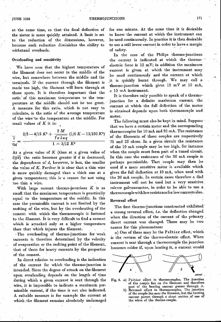
~) One of these may be the Peltier effect, whichis the reverse of the thermo-electric effect. Whencurrent is sent through a thermocouple the junctionbecomes colder if, upon heating it, a current would
....
~670F •
Fig. 6. a) Peltier effect in thermocouples. The junctionof the couple lies on the filament and thereforepart of the heating current passes through it.
b) Reversal effect in thermocouples. The junctionof the couple lies near the filament, but the heatingcurrent passes through a short section of one ofthe wires of the thermo-couple, .

172 PHILIPS TECHNICAL REVIEW Vol. 3, No. 6
have occurred in the same direction, and vice versa.The Peltier effect therefore occurs in the originalthermo-electric ammeter by Kl eme.n ó ié, and alsoin' the case of the commonly used bridge circuitswhich we shall not discuss here. With modernthermocouples also the effect may appear whenthe thermo-junction is not electrically insulatedfrom the filament, and when it lies exactly on thefilament (see fig. 6a). In this type of constructionpart of the primary current also passes through.the junction of the thermocouple and gives riseto the Peltier effect. This may be avoided byplacing the junction near but not on the filament.b) Even when the junction does not lie on the
filament a reversing effect mayalso appear (seefig: 6b). At the point where filament and thermo-couple touch each other, part ofthe primary currentwill always pass through part of the thermocouple.Due to the resistance of the latter a potentialdifference will arise which leads to a small extracurrent through the meter' whose direction isreversed when the direction of the primary currentis reversed. In order to avoid this the thermocouplemust be insulatèd from the filament; when this hasbeen done the reversal effect will he found tohave disappeared and the thermocouple can hecalibrated with direct current.
Sjleed of indication
The ,final deflection is not rapidly reachedwith a thermo-ammeter. The main reason forthis is that a temperatjrre equilibrium must heestablished in the filament and the thermocouple.Since the thermocouple itself does not carry theprimary current, the heating up of the junction'mu~t take place' from the filament by conduction,for which some time is necessary. A type of con-struction is possible in which the thermocouplealsó serves as filament (see fig.7); in this casethe heat is developed in every, element of' volumeof the thermocouple, so that only 'a small amountof heat needs to be transported by conduction,and the 'final deflection is quickly attained. An
2670S
Fig. 7. Thermocouple with direct heating. The condenser isintroduced so that the direct voltage' given by the couplemay not be short-circuited by the sourceof alternating current.The self-inductance is introduced 'to prevent the alternating
. current from passing through the direct current metre.
elaboration of this construction is formed by thebridge arrangements in which a number of thermo-couples are joined to form a square; the disadvantageof this method is the presence of a strong Peltiereffect.As was noted. above, the heat capacity also has
some influence on the speed of indication; thereforesmall dimensions are desirable. The resistance ofthe thermocouple mayalso effect the speed. of'indication because with too low resistance thedamping of the 'metre is considerable.
Dependence of the indication on frequency
The heat development in a wire is independentof the frequency of the alternating current used forheating up to very high frequencies. At very highfrequencies, however, the so-called skin effectappears, and the resistance, and therefore the heatdevelopment also, are greaterthan at low frequencies.For the thickness of wire used the influence ofthis effect is only appreciable at wave lengths ofless than one metre, so that it need not usuallybe taken into account.It is quite another question with the influences
of various capacities (see fig. 8). The capacity in
,,/;~'/
F'nn-IU'"uu
..:lil-uu
26.704
Fig. a:Diagram of a thermocouple withthe various parasiticcapacities. .
parallel. with the filament is the cause of partof the current to be measured not passingthrough the filament, and the' result is thatthe 0deflection of the, metre is' too small. This. is sometimes compensated by the self-inductiön oftlfe filament. The capacity between the supplyleads has the same effect. There is further capacitybetween the filament and the thermocouple whichis connected with earth capacitatively through thegalvanometer. This capacity is further increased bythe fact that the leads of the filament and thoseof the thermocouple are close together in the pinch

JUNE 1938 THERMOJUNCTIONS 173
of the bulb and in the base. This capacity may bepartially reduced by using thermocouples withoutbases in measurements at very high frequencies.The third kind of capacitive influence, the capacityof the leads to earth, is hereby also very muchreduced. In order to overcome the last-mentionedinfluence it is absolutely essential that one sideof the filament be earthed.The influence of these parasitic capacities becomes
greater the higher the resistance of the filament.A thermocouple with a filament having a resistanceof 20 ohms gives reliable indications at a wavelength of 6 metres within 1 per cent; when thethermocouple is used without a base the indicationis still reliable within 1 per cent at wave lengthsof 3 meters.
Advantages in the use of thermc-ammeters
In conclusion we give the following list of theadvantages connected with the use ofthermocouplesfor measuring alternating current. .a) The effective value of the alternating current
is measured because use is made of the developmentof heat, and therefore of a mechanism which variesessentially with the square of the current. For thisreason the measurement is very little affected bythe presence of higher harmonics in the currentmeasured, and it is not at all affected by the phaseof these harmonics. This is a common property ofall thermal instruments.b) Up to a very high frequency the indication
is independent of the frequency of the currentmeasured.c) The energy consumption is small compared
with that of dynamometers and soft-iron instru-ments.
Fig. 9. Thermocouple assembled.
d) The delicate part ofthe measuring arrangement,the thermocouple itself, is easily renewable; inthis connection the quadratic, or at least reliablyconstant, characteristic is also important.
Survey of the Philips thermojunctions
The P hili ps thermo-electric meters are con-structed with the above considerations in view.Fig. 9 is a photograph of a fully assembled thermo-couple and jig. 10 shows the interior of such aninstrument. The cover serves not only for decora-tion, but also for shielding the instrument fromheat radiation from the surroundings.
Fig. 10. Interior of a thermocouple.
The table gives a survey of the various propertiesof the instruments. With all types the temperaturecoefficient of the resistance of the filament is small;for most measurements it may be neglected. Theindication is practically quadratic up to halfthe filament current, where the thermo-electricforce is 12 mV; the deviation from the quadraticvaria tion is 2 per cent at the most in this range,the thermo-electromotive force is about 4 mV atthat current, so 'that a full deflection can still beobtained with sensitive dial instruments. Thethermocouple is insulated electrically from thefilament; the instruments can therefore be calibratedwith direct current.
ThlTh2Th3Th4Th5
153075
150300
2040
100200350
12 mV resistance resistance contin- maximum
Type EMF of the of the permis-at uous use siblenumber filament thermo- up to currentapprox. ohm couple mAmA mA
75237.52.21.1
53333
102040100200
174 PHILIPS TECHNICAL REVIEW Vol. 3, No. 6
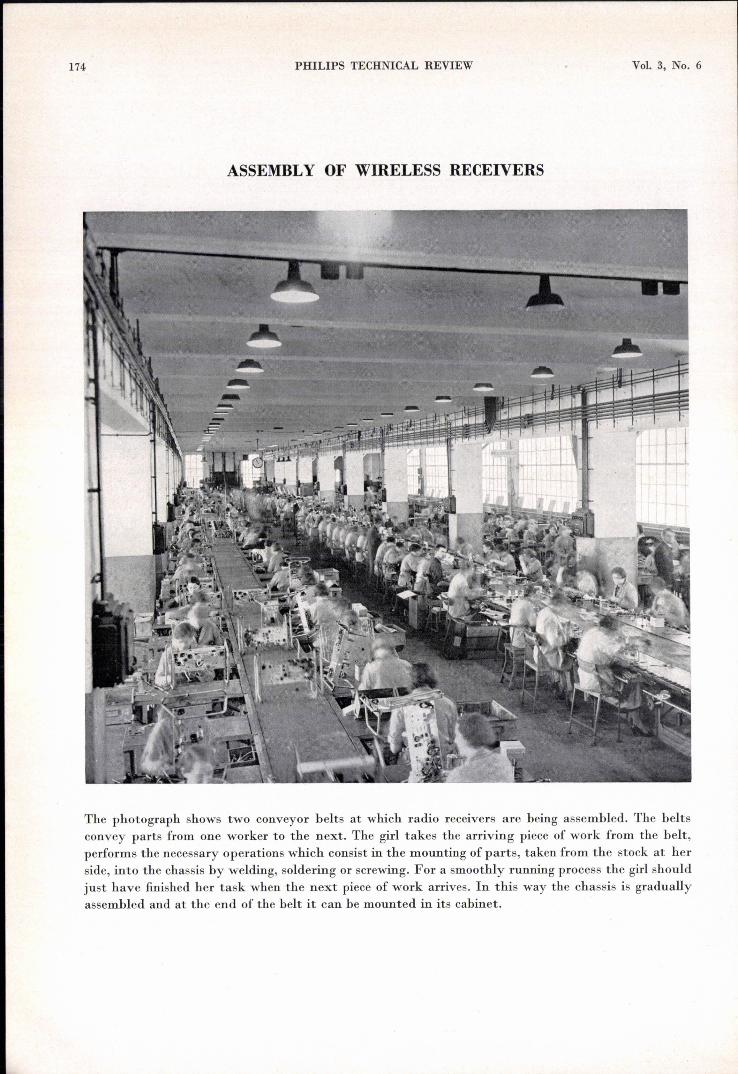
ASSEMBLY OF WIRELESS RECEIVERS
The photograph shows two conveyor belts at which radio receivers are being assembled. The beltsconvey parts from one worker to the next. The girl takes the arriving piece of work from the belt,performs the necessary operations which consist in the mounting of parts, taken from the stock at herside, into the chassis by welding, soldering or screwing. For a smoothly running process the girl shouldjust have finished her task when the next piece of work arrives. In this way the chassis is graduallyassembled and at the end of the belt it can be mounted in its cabinet.