Thermoforming Design Guide - CWThomas · Thermoforming Design Guide . 2 ... Thermoforming is the...
35
Thermoforming Design Guide
Transcript of Thermoforming Design Guide - CWThomas · Thermoforming Design Guide . 2 ... Thermoforming is the...
Thermoforming Design Guide
2
CW Thomas 8000 State Road Philadelphia, PA 19136
Tel 215‐335‐0200 / 1‐800‐523‐0856 / Fax 215‐335‐4310 www.cwthomas.com Email: [email protected]
Table of Contents
Introduction…………………………………………………………………...........3
Thermoformed Applications………………………………..……………………....4
Vacuum Forming Process………………………………..…………………………6
Pressure Forming Process……………………………………..……………………9
Mold Design…………………………………………………..…….…………….11
Thermoplastics………………………......……………………………..…….……12
Blueprint Dimensions & Mold Tolerances…………………………...…………...22
Draw Ratios & Plug Assists………………………………………………………25
Draft Angles……………………………………….………………………...……27
Radii & Chamfers…………………..…………………………..…………………28
Undercuts……………..……………………………….…………………………..29
Textures………………….…………………………………………..……………31
Ribs and Louvers……………………………..………………………………...…32
Fastening…………………………………………………………………………..33
Conclusion……………………………………..………………………………….34
3
CW Thomas 8000 State Road Philadelphia, PA 19136
Tel 215‐335‐0200 / 1‐800‐523‐0856 / Fax 215‐335‐4310 www.cwthomas.com Email: [email protected]
Introduction
Thermoformed plastic products are all around us in every environment and play a major part in our everyday lives. It is a very adaptable process used to create an enormous range of products from packaging trays to enclosures on space shuttles. It is also used in a broad range of design prototypes for products to be produced in other engineered processes.
Thermoforming is the heating of a plastic sheet which is then draped over a mold while vacuum is applied. The molding is then cooled before it is ejected from the mold using reverse pressure.
Thermoforming covers all processes which involve heat to shape polymers. In this guide we will focus on the vacuum forming and pressure forming processes. We will also take a look at information about draw ratios, dimensional tolerances, radii and chamfers, undercuts, and plug assists as well as other information regarding the technical side of thermoforming processes. In this guide we hope to provide insight on these processes. We hope it aids in taking any assumptions out of the process and proves useful as a means of technical and engineering support. Here at CW Thomas, we are always available to support you at any phase of your production. On the next page we have created a list of the several examples of applications for thermoformed parts.
4
CW Thomas 8000 State Road Philadelphia, PA 19136
Tel 215‐335‐0200 / 1‐800‐523‐0856 / Fax 215‐335‐4310 www.cwthomas.com Email: [email protected]
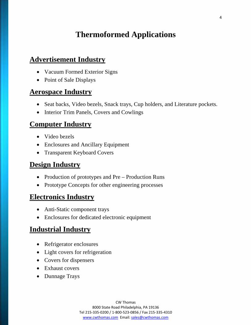
Thermoformed Applications
Advertisement Industry
Vacuum Formed Exterior Signs
Point of Sale Displays
Aerospace Industry
Seat backs, Video bezels, Snack trays, Cup holders, and Literature pockets.
Interior Trim Panels, Covers and Cowlings
Computer Industry
Video bezels
Enclosures and Ancillary Equipment
Transparent Keyboard Covers
Design Industry
Production of prototypes and Pre – Production Runs
Prototype Concepts for other engineering processes
Electronics Industry
Anti-Static component trays
Enclosures for dedicated electronic equipment
Industrial Industry
Refrigerator enclosures
Light covers for refrigeration
Covers for dispensers
Exhaust covers
Dunnage Trays
5
CW Thomas 8000 State Road Philadelphia, PA 19136
Tel 215‐335‐0200 / 1‐800‐523‐0856 / Fax 215‐335‐4310 www.cwthomas.com Email: [email protected]
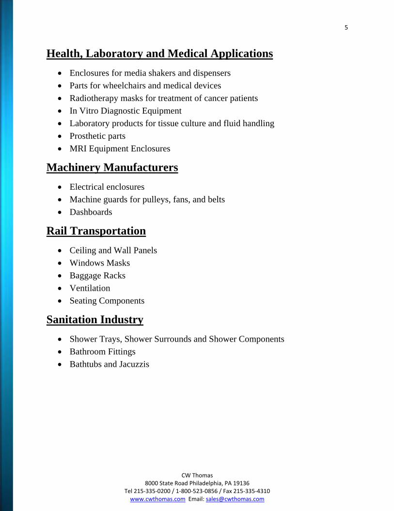
Health, Laboratory and Medical Applications
Enclosures for media shakers and dispensers
Parts for wheelchairs and medical devices
Radiotherapy masks for treatment of cancer patients
In Vitro Diagnostic Equipment
Laboratory products for tissue culture and fluid handling
Prosthetic parts
MRI Equipment Enclosures
Machinery Manufacturers
Electrical enclosures
Machine guards for pulleys, fans, and belts
Dashboards
Rail Transportation
Ceiling and Wall Panels
Windows Masks
Baggage Racks
Ventilation
Seating Components
Sanitation Industry
Shower Trays, Shower Surrounds and Shower Components
Bathroom Fittings
Bathtubs and Jacuzzis
6
CW Thomas 8000 State Road Philadelphia, PA 19136
Tel 215‐335‐0200 / 1‐800‐523‐0856 / Fax 215‐335‐4310 www.cwthomas.com Email: [email protected]
Vacuum Forming
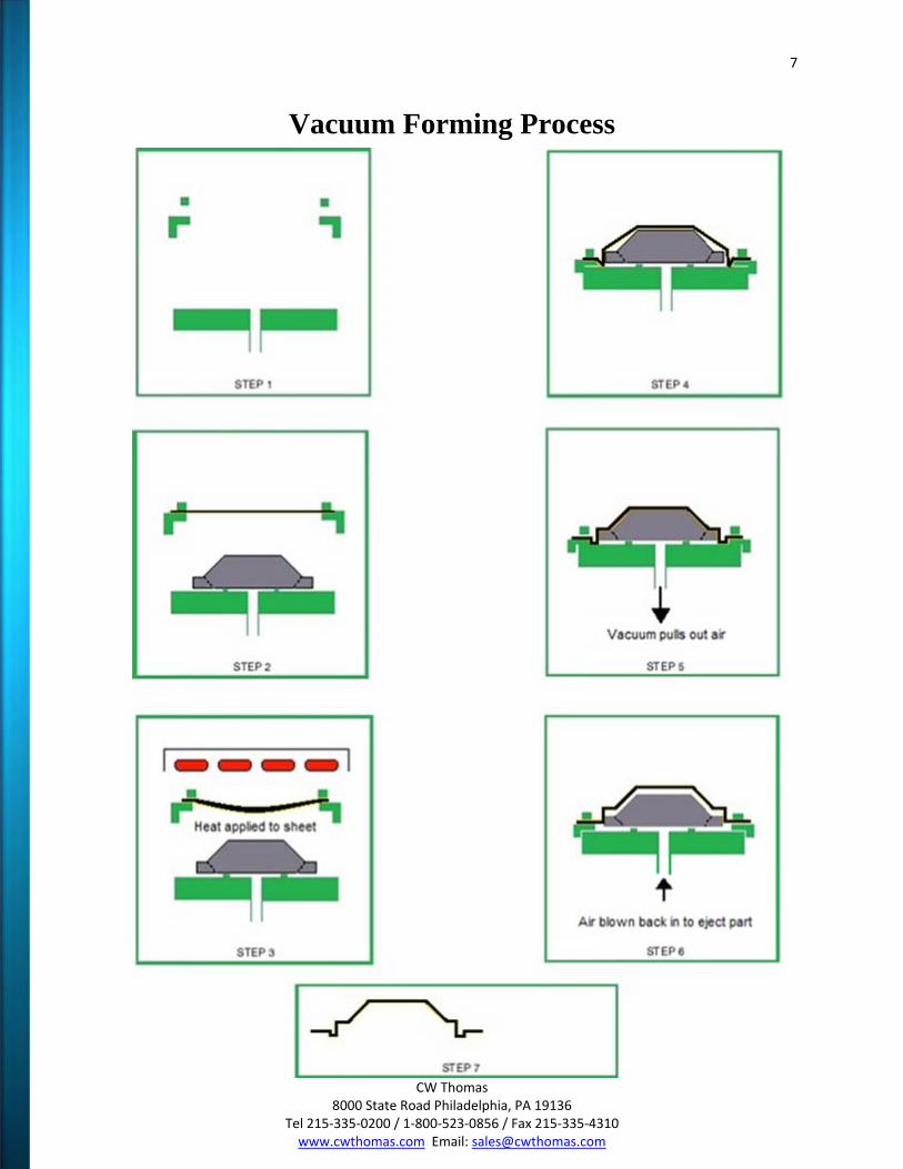
The most widely used method of thermoforming is vacuum forming. A male or female mold tool is mounted in a machine and a heated sheet is located over or under the tool depending on numerous variables. Vacuum is then applied to remove the air between the sheet and the mold. The vacuum is used to transfer the heated sheet into contact with the mold surface. This pressure holds the sheet until the temperature decreases below its heat distortion temperature.
All thermoforming practices are basically a stretching process. The stretching of a flat sheet of plastic into a larger shape creates a larger surface area and a reduction in the sheet’s original thickness. The thinning down of the sheet’s original thickness is not always constant. However, our processing techniques allow us to influence the material distribution where it’s required.
The area of the sheet that first comes in contact to the mold surface stretches and thins out the least. This is because the material that contacts the mold first begins to cool first and becomes stronger and resists further stretching and thinning.
Vacuum forming is a cost-effective process for producing low volume, large sized parts at a practical price. The advantages of vacuum forming is the ability to form large parts without costly equipment and tooling, low cost mold and design revisions, ease of manufacturing large quantities, and the ability to create padded foam filled or laminated parts. Thermoplastics most commonly used are HIPS, PVC, ABS, PP, Acrylic and Polycarbonates. There are also special types such as Turlan, Teflon and Espel. We can also provide value added services such as pad printing, hot stamping, painting and silk screening.
7
CW Thomas 8000 State Road Philadelphia, PA 19136
Tel 215‐335‐0200 / 1‐800‐523‐0856 / Fax 215‐335‐4310 www.cwthomas.com Email: [email protected]
Vacuum Forming Process
8
CW Thomas 8000 State Road Philadelphia, PA 19136
Tel 215‐335‐0200 / 1‐800‐523‐0856 / Fax 215‐335‐4310 www.cwthomas.com Email: [email protected]
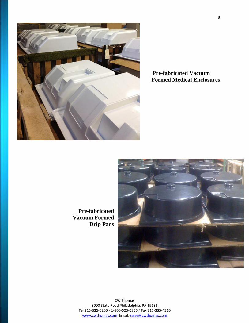
Pre-fabricated Vacuum Formed Medical Enclosures
Pre-fabricated Vacuum Formed
Drip Pans
9
CW Thomas 8000 State Road Philadelphia, PA 19136
Tel 215‐335‐0200 / 1‐800‐523‐0856 / Fax 215‐335‐4310 www.cwthomas.com Email: [email protected]
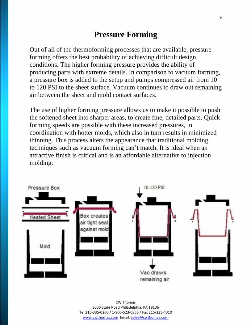
Pressure Forming
Out of all of the thermoforming processes that are available, pressure forming offers the best probability of achieving difficult design conditions. The higher forming pressure provides the ability of producing parts with extreme details. In comparison to vacuum forming, a pressure box is added to the setup and pumps compressed air from 10 to 120 PSI to the sheet surface. Vacuum continues to draw out remaining air between the sheet and mold contact surfaces. The use of higher forming pressure allows us to make it possible to push the softened sheet into sharper areas, to create fine, detailed parts. Quick forming speeds are possible with these increased pressures, in coordination with hotter molds, which also in turn results in minimized thinning. This process alters the appearance that traditional molding techniques such as vacuum forming can’t match. It is ideal when an attractive finish is critical and is an affordable alternative to injection molding.
10
CW Thomas 8000 State Road Philadelphia, PA 19136
Tel 215‐335‐0200 / 1‐800‐523‐0856 / Fax 215‐335‐4310 www.cwthomas.com Email: [email protected]
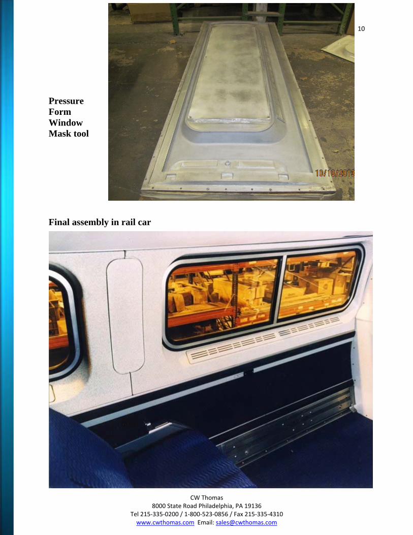
Pressure Form Window Mask tool
Final assembly in rail car
11
CW Thomas 8000 State Road Philadelphia, PA 19136
Tel 215‐335‐0200 / 1‐800‐523‐0856 / Fax 215‐335‐4310 www.cwthomas.com Email: [email protected]
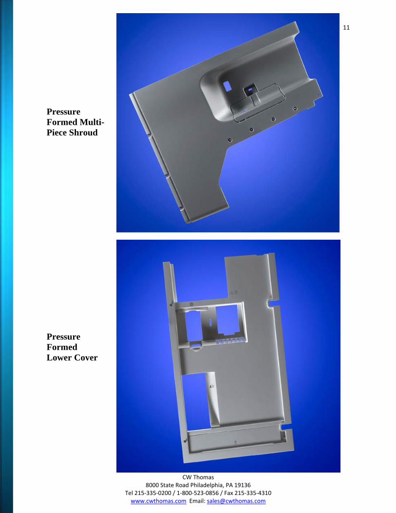
Pressure Formed Multi-Piece Shroud
Pressure Formed Lower Cover

12
CW Thomas 8000 State Road Philadelphia, PA 19136
Tel 215‐335‐0200 / 1‐800‐523‐0856 / Fax 215‐335‐4310 www.cwthomas.com Email: [email protected]
Mold Design
Since 1946, CW Thomas has developed a distinctive and well sought after quality of thermoformed plastics parts. The expertise used to produce molds that manufacture exceptional plastic parts are simply unmatched. We are a thermoforming company that takes into consideration all of the variables that will affect the final part during our mold design process. We staff expert designers and machinists, all of which are fluent in today’s ever changing cutting edge software to assist in creating a precision tool. We house all of the equipment and tooling needed to manufacture the majority of our molds right here at CW Thomas. This provides enhanced flexibility, quality and delivery times to our customers. Thermoforming molds can be created from a variety of materials. Choosing the material is based on the dimensions of the part, polymer selection, features, accuracy and quantity. As thermoforming is a process completed with a single sided tool, the critical surface of the part should always face the tool. This is considered the controlled surface with the most precise tolerances and surfaces. The features created on the controlled side of the part will cause the back side of the part to follow but will differentiate due to polymer distribution. Our molds are created entirely in our facility by expert mold makers who have over 25 years in the industry. The aluminum molds are designed by our engineers in our CAD software then CNC programmed for one of our Haas 3 axis vertical mills or CMS 5 axis mills that machines the desired pattern. CW Thomas stands out from the rest of the thermoforming industry by isolating and defining each variable in the mold making process, which decreases our aluminum mold production lead times.
13
CW Thomas 8000 State Road Philadelphia, PA 19136
Tel 215‐335‐0200 / 1‐800‐523‐0856 / Fax 215‐335‐4310 www.cwthomas.com Email: [email protected]
Thermoplastics
Thermoplastics are polymers that exist as a group of molecules, or atoms. The atoms are arranged in many different combinations which all have varying properties and encompass a large range of additives to allow each material to have its own unique characteristics. Most commonly, amorphous polymers are easier to vacuum form as they have a larger range of forming temperatures. As heat is applied to an amorphous material it becomes soft and pliable. Once it reaches this temperature it is now in its glass transition state. Once heated to its higher range it will eventually reach its viscous state temperature. Crystalline and semi-crystalline polymers have a much narrower band of forming temperatures as they can easily go from its glass state temperature to its melt transition state temperature. This melt transition only occurs in portions of the polymer where crystalline molecule chains are located. When using crystalline polymers it is important that the correct temperature control is applied. Comparing the two types of thermoplastics, the forming temperature bands for amorphous polymers is much larger and results in a wider process window compared to a semi-crystalline polymer. This equates in an improved melt strength and results in decreased sag as the melt transition temperature is reached. Different thermoplastics will have unique characteristics and can be tailored to your company’s specific application. Ideally the polymer should be easily formed with a low forming temperature, good melt strength, good flow properties, high impact strength and minimal shrinkage on cooling.
14
CW Thomas 8000 State Road Philadelphia, PA 19136
Tel 215‐335‐0200 / 1‐800‐523‐0856 / Fax 215‐335‐4310 www.cwthomas.com Email: [email protected]
Acrylonitrile Butadiene Styrene (ABS)
Properties A hard, rigid amorphous thermoplastic with good impact strength and weather resistance. It contains a rubber property which provides it an enhanced impact
resistance. Available with different textures and finishes in a range of thickness, as well as fire retardant and UV stabilized grades.
Formability
Good and forms to a high detail.
Strength Good - High impact strength
Hygroscopic
Yes
Shrinkage Rates High Impact .005”-.007”/ inch High Heat .004”-.005”/ inch
Solvent / Filler
Dichloromethane, Toluene and Methyl Ethyl Ketene solvent will make filler paste.
Machining / Finishing Machines well with Routers, Circular Saws, and Band saws. Also takes all sprays
and capable of being guillotined and roller cut.
Clear No
Applications
Sanitary Parts, Luggage, Vehicular Parts, Electrical Enclosures
15
CW Thomas 8000 State Road Philadelphia, PA 19136
Tel 215‐335‐0200 / 1‐800‐523‐0856 / Fax 215‐335‐4310 www.cwthomas.com Email: [email protected]
Acrylic - PMMA (Perspex, Oroglas, Plexiglas)
Properties A high quality hard amorphous plastic with decent clarity that can be worked after forming. Cast acrylic will not respond well as it displays a very small usable plastic zone. As a result it will only produce general contours with large drape radii. Also
provides great UV resistance.
Formability Tends to be brittle and is temperature sensitive.
Strength
Medium to High strength
Hygroscopic Yes
Shrinkage Rate
General Purpose Acrylic .020”-.035” / inch High Impact Acrylic .004”-.008” / inch High Heat Acrylic .003”-.010” / inch
Solvent / Filler
Tensol, solvent and gap filler.
Machining/ Finishing Susceptible to shattering and good for hand working.
Clear Yes
Colors
Opaque and translucent colors
Applications Machine Guards, Light Diffusers, Signs, Roof Lights and Domes, Baths and
Sanitary Ware
16
CW Thomas 8000 State Road Philadelphia, PA 19136
Tel 215‐335‐0200 / 1‐800‐523‐0856 / Fax 215‐335‐4310 www.cwthomas.com Email: [email protected]
Co-Polyester - (PETG / VIVAK)
Properties An easy forming amorphous thermoplastic. It is FDA approved for food
applications. Optically very good with excellent fabricating performance. Also thermoforms with ease, utilizing low temperatures and fast cycle times. Not
recommended for use with highly alkaline solutions.
Formability Very Good and forms to a high detail
Strength
Good - High Impact
Hygroscopic Not normally required.
Solvent / Filler
Cementing can be done using solvents or commercial glues. Capable of being ultrasonically welded.
Machining / Finishing
Capable of being guillotined, saw cut or router. Die Cutting and punching also possible up to .125, paints and inks for polyester can be used for printing on PETG.
Clear Yes
Colors Limited
Applications
Point of Sale and Displays, Medical Applications, Machine Guards
17
CW Thomas 8000 State Road Philadelphia, PA 19136
Tel 215‐335‐0200 / 1‐800‐523‐0856 / Fax 215‐335‐4310 www.cwthomas.com Email: [email protected]
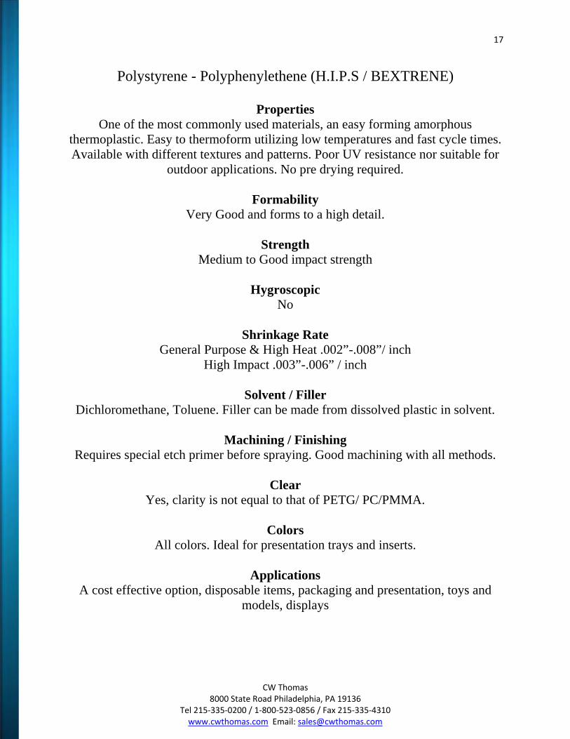
Polystyrene - Polyphenylethene (H.I.P.S / BEXTRENE)
Properties One of the most commonly used materials, an easy forming amorphous
thermoplastic. Easy to thermoform utilizing low temperatures and fast cycle times. Available with different textures and patterns. Poor UV resistance nor suitable for
outdoor applications. No pre drying required.
Formability Very Good and forms to a high detail.
Strength
Medium to Good impact strength
Hygroscopic No
Shrinkage Rate
General Purpose & High Heat .002”-.008”/ inch High Impact .003”-.006” / inch
Solvent / Filler
Dichloromethane, Toluene. Filler can be made from dissolved plastic in solvent.
Machining / Finishing Requires special etch primer before spraying. Good machining with all methods.
Clear
Yes, clarity is not equal to that of PETG/ PC/PMMA.
Colors All colors. Ideal for presentation trays and inserts.
Applications
A cost effective option, disposable items, packaging and presentation, toys and models, displays
18
CW Thomas 8000 State Road Philadelphia, PA 19136
Tel 215‐335‐0200 / 1‐800‐523‐0856 / Fax 215‐335‐4310 www.cwthomas.com Email: [email protected]
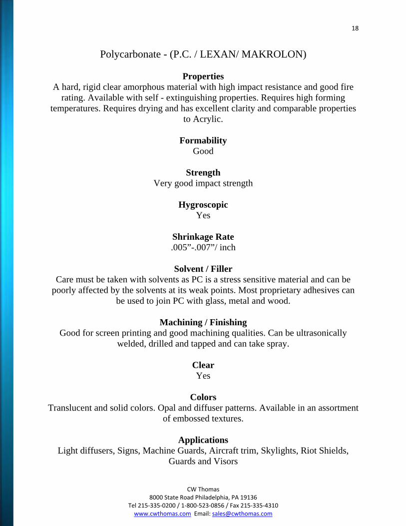
Polycarbonate - (P.C. / LEXAN/ MAKROLON)
Properties A hard, rigid clear amorphous material with high impact resistance and good fire
rating. Available with self - extinguishing properties. Requires high forming temperatures. Requires drying and has excellent clarity and comparable properties
to Acrylic.
Formability Good
Strength
Very good impact strength
Hygroscopic Yes
Shrinkage Rate .005”-.007”/ inch
Solvent / Filler
Care must be taken with solvents as PC is a stress sensitive material and can be poorly affected by the solvents at its weak points. Most proprietary adhesives can
be used to join PC with glass, metal and wood.
Machining / Finishing Good for screen printing and good machining qualities. Can be ultrasonically
welded, drilled and tapped and can take spray.
Clear Yes
Colors
Translucent and solid colors. Opal and diffuser patterns. Available in an assortment of embossed textures.
Applications
Light diffusers, Signs, Machine Guards, Aircraft trim, Skylights, Riot Shields, Guards and Visors
19
CW Thomas 8000 State Road Philadelphia, PA 19136
Tel 215‐335‐0200 / 1‐800‐523‐0856 / Fax 215‐335‐4310 www.cwthomas.com Email: [email protected]
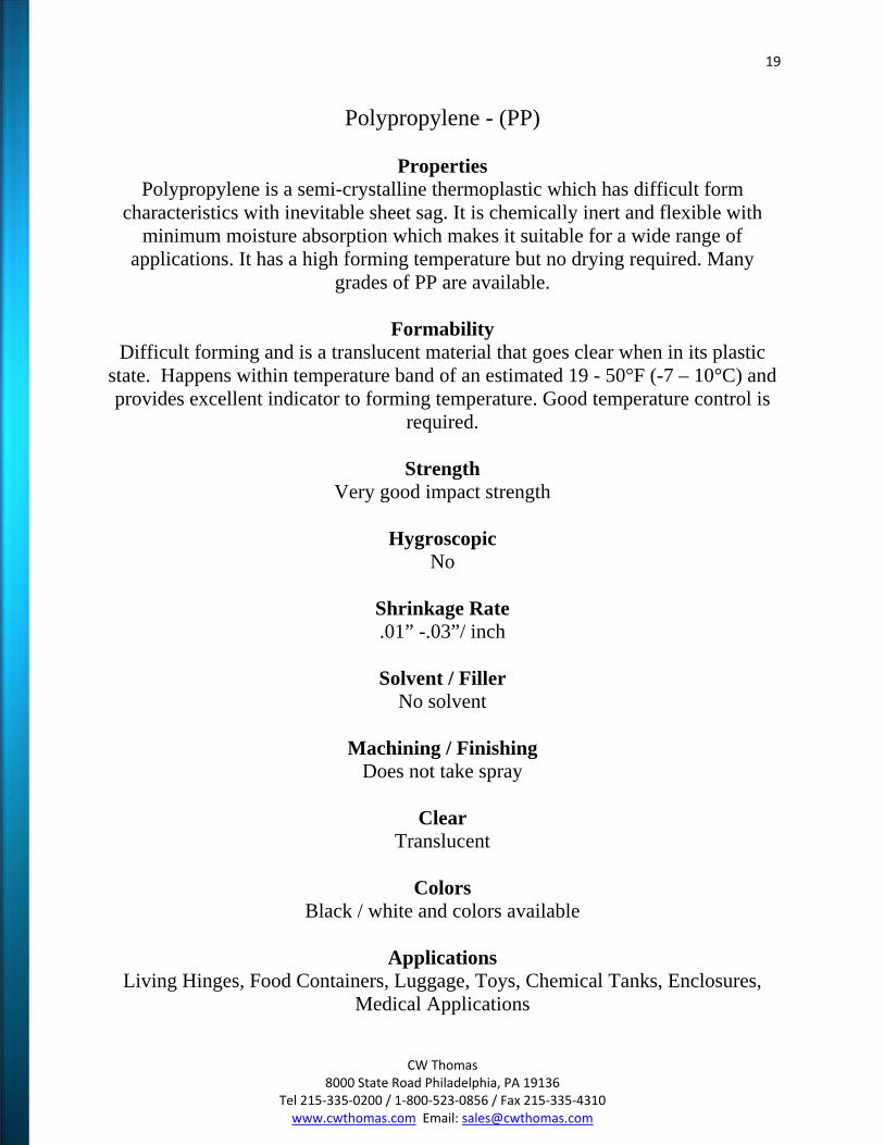
Polypropylene - (PP)
Properties Polypropylene is a semi-crystalline thermoplastic which has difficult form
characteristics with inevitable sheet sag. It is chemically inert and flexible with minimum moisture absorption which makes it suitable for a wide range of
applications. It has a high forming temperature but no drying required. Many grades of PP are available.
Formability
Difficult forming and is a translucent material that goes clear when in its plastic state. Happens within temperature band of an estimated 19 - 50°F (-7 – 10°C) and provides excellent indicator to forming temperature. Good temperature control is
required.
Strength Very good impact strength
Hygroscopic
No
Shrinkage Rate .01” -.03”/ inch
Solvent / Filler
No solvent
Machining / Finishing Does not take spray
Clear
Translucent
Colors Black / white and colors available
Applications
Living Hinges, Food Containers, Luggage, Toys, Chemical Tanks, Enclosures, Medical Applications
20
CW Thomas 8000 State Road Philadelphia, PA 19136
Tel 215‐335‐0200 / 1‐800‐523‐0856 / Fax 215‐335‐4310 www.cwthomas.com Email: [email protected]
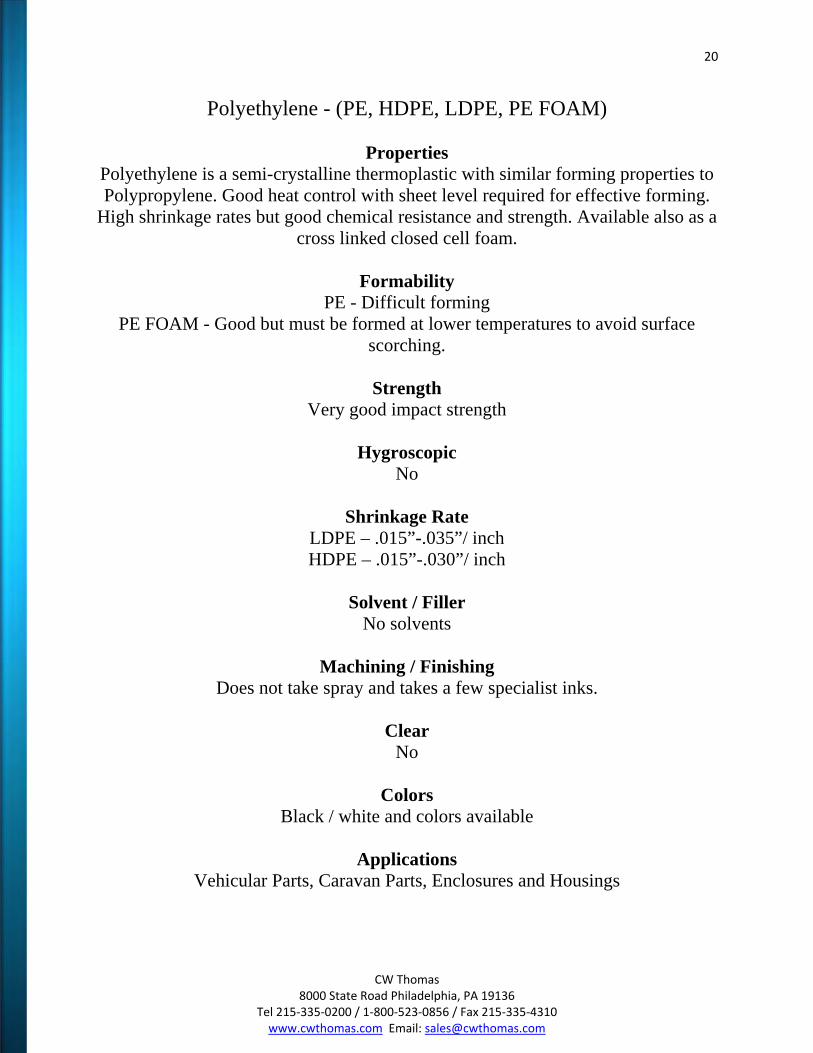
Polyethylene - (PE, HDPE, LDPE, PE FOAM)
Properties Polyethylene is a semi-crystalline thermoplastic with similar forming properties to Polypropylene. Good heat control with sheet level required for effective forming.
High shrinkage rates but good chemical resistance and strength. Available also as a cross linked closed cell foam.
Formability
PE - Difficult forming PE FOAM - Good but must be formed at lower temperatures to avoid surface
scorching.
Strength Very good impact strength
Hygroscopic
No
Shrinkage Rate LDPE – .015”-.035”/ inch HDPE – .015”-.030”/ inch
Solvent / Filler
No solvents
Machining / Finishing Does not take spray and takes a few specialist inks.
Clear
No
Colors Black / white and colors available
Applications
Vehicular Parts, Caravan Parts, Enclosures and Housings
21
CW Thomas 8000 State Road Philadelphia, PA 19136
Tel 215‐335‐0200 / 1‐800‐523‐0856 / Fax 215‐335‐4310 www.cwthomas.com Email: [email protected]
Polyvinylchloride - (PVC)
Properties Strong, rigid thermoplastic with decent transparency in thinner gauges. It has good
chemical and fire retardant characteristics that is highly resistant to solvents. Thicker materials are strong with good impact strength and are best suited to
outdoor industrial applications.
Formability Forms well but with an inclination to web.
Strength
Good
Hygroscopic No
Shrinkage Rate
PVC Semi Rigid .008”-.025”/ inch PVC Flexible .002-.006”/ inch PVC Rigid .002”-.004” / inch
Solvent / Filler
Toluene may be used - no others solvents suitable.
Machining / Finishing Takes some specialist inks. Hot air weld, glue, or ultrasonic weld.
Clear Yes
Colors
Black / white and colors available
Applications Car Trim, Packaging, and Machine Guards
22
CW Thomas 8000 State Road Philadelphia, PA 19136
Tel 215‐335‐0200 / 1‐800‐523‐0856 / Fax 215‐335‐4310 www.cwthomas.com Email: [email protected]
Blueprint Dimensions & Mold Tolerances
Blueprint Dimension Overview
One of the most common mistakes in thermoforming is that the dimensions are created from the uncontrolled surface of the part. Once the controlled mold surface has been determined there should be no error on dimensioning. All of the dimensions, formed in and trimmed in, must then be referenced to the controlled side of the part. Blueprint Recommendations: All dimensions on the blueprint should be created from the controlled side of the part. When possible the starting gauge of the sheet should also be identified.
Mold Tolerances Overview
Thermoformed part tolerances are decided by a multitude of variables. This includes the coefficient of thermal expansion of the resin, extrusion conditions, temperature and type of the mold, consistency of the forming process, quality of trimming fixtures and the method of trimming.
Tolerance Recommendations: For molded in dimensions of parts from a machined aluminum male mold use +/-.015” for the first inch adding an additional +/-.001” for each additional inch after 12”. For female tools you should use +/-.010” + an additional .0015” due to process control loss of the material shrinking away from the tool surface during cooling. Trimmed dimensions, regardless of the mold but using CNC trimming equipment, should have a tolerance of +/-.015”. Details: The majority of thermoforming resins have a coefficient of thermal expansion in the range of .000060” to .000120” per ºF per inch (6.0 – 12.0 x 10⁻⁵ in./ºF/in.). This will be an important variable when the part is large and the forming temperature of the part can change. On large parts over 48” it is best to add a note to the drawing specifying a temperature at which the dimensions should be
23
CW Thomas 8000 State Road Philadelphia, PA 19136
Tel 215‐335‐0200 / 1‐800‐523‐0856 / Fax 215‐335‐4310 www.cwthomas.com Email: [email protected]
measured. We have found 40-50 ºF (4 - 10°C) temperature variances in our plant summer to winter. Extrusion quality will affect the part many ways. The extrusion quality is controlled by variables such as extrusion speed, temperature, direction and gauge will modify the amount of stress that the sheet has when it is delivered to the mold surface. Changes in that stress will affect the rate at which the part molds therefore changing the dimensions. Molds must be temperature controlled with internal cooling channels to allow for consistent mold temperature. Aluminum is the material of choice because it’s capable of a very high coefficient of thermal conductivity which allows for a very consistent cooling cycle time through the entire production run. Wood, epoxy, or plaster can’t compare to the quality aluminum molds can produce. The forming process must be very consistent from run to run to secure a dimensional consistency. The use of precise digital measurement controls on the forming machine allows for a high degree of accuracy in the cycle times. A change in the amount of time the part spends in the mold has a direct effect on the amount of part shrinkage that occurs. The part must be held in the mold until the set temperature of the resin has been reached.
Dimensioning outline: It is not routine to specify dimensions to the non-tool side of the part. This is due to the need to increase the tolerance significantly when including wall thickness variation. In such cases when a tight tolerance is needed on the non-tool side of parts, second operation machining may be considered. The tolerances listed below are an industry standard. We can assist you during your design in achieving a tighter set of tolerances if your parts require it. Formed features: Vacuum Forming +/- .015” (.4mm) + .001” (.025mm) per inch after 12” (305mm) Pressure Forming +/- .010” (.3mm) +.001” (.025mm) per inch after 12” (305mm) CNC Trim features: Trimming +/- .015 (.4mm) Holes & Slots +/- .010” (.3mm)
24
CW Thomas 8000 State Road Philadelphia, PA 19136
Tel 215‐335‐0200 / 1‐800‐523‐0856 / Fax 215‐335‐4310 www.cwthomas.com Email: [email protected]
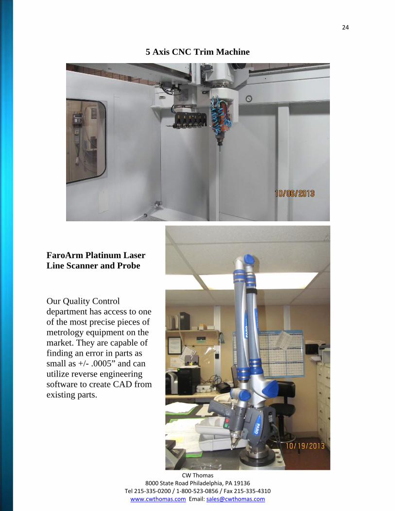
5 Axis CNC Trim Machine
FaroArm Platinum Laser Line Scanner and Probe
Our Quality Control department has access to one of the most precise pieces of metrology equipment on the market. They are capable of finding an error in parts as small as +/- .0005” and can utilize reverse engineering software to create CAD from existing parts.
25
CW Thomas 8000 State Road Philadelphia, PA 19136
Tel 215‐335‐0200 / 1‐800‐523‐0856 / Fax 215‐335‐4310 www.cwthomas.com Email: [email protected]
Draw Ratio & Plug Assists
Draw Ratio Overview
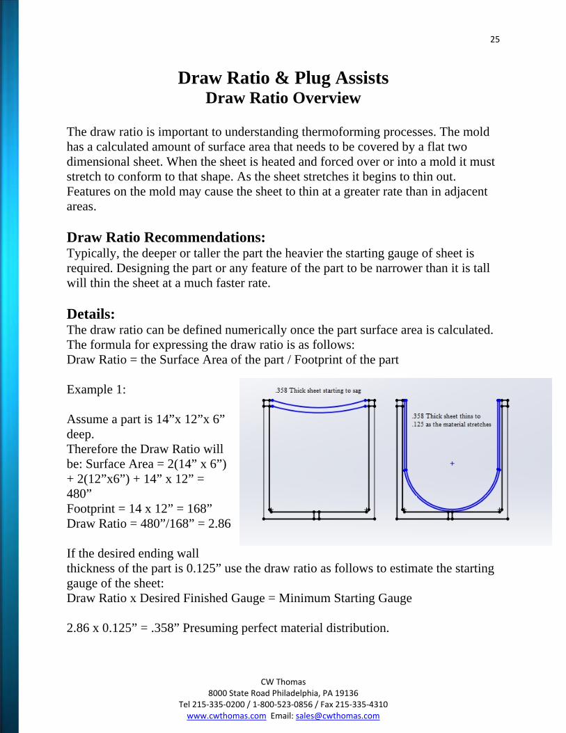
The draw ratio is important to understanding thermoforming processes. The mold has a calculated amount of surface area that needs to be covered by a flat two dimensional sheet. When the sheet is heated and forced over or into a mold it must stretch to conform to that shape. As the sheet stretches it begins to thin out. Features on the mold may cause the sheet to thin at a greater rate than in adjacent areas. Draw Ratio Recommendations: Typically, the deeper or taller the part the heavier the starting gauge of sheet is required. Designing the part or any feature of the part to be narrower than it is tall will thin the sheet at a much faster rate. Details: The draw ratio can be defined numerically once the part surface area is calculated. The formula for expressing the draw ratio is as follows: Draw Ratio = the Surface Area of the part / Footprint of the part Example 1: Assume a part is 14”x 12”x 6” deep. Therefore the Draw Ratio will be: Surface Area = 2(14” x 6”) + 2(12”x6”) + 14” x 12” = 480” Footprint = 14 x 12” = 168” Draw Ratio = 480”/168” = 2.86 If the desired ending wall thickness of the part is 0.125” use the draw ratio as follows to estimate the starting gauge of the sheet: Draw Ratio x Desired Finished Gauge = Minimum Starting Gauge 2.86 x 0.125” = .358” Presuming perfect material distribution.
26
CW Thomas 8000 State Road Philadelphia, PA 19136
Tel 215‐335‐0200 / 1‐800‐523‐0856 / Fax 215‐335‐4310 www.cwthomas.com Email: [email protected]
Example 2: Assume a part size of 8” x 11” x 5” deep. Surface Area = 2(8” x 5”) + 2(11” x 5”) + (8” x 11”) = 278” Footprint = 8” x 11” = 88” Draw Ratio = 278”/88” = 3.16 If the desired ending wall thickness is 0.100” use the draw ratio value as follows: 3.16 x 0.100” = .316” starting gauge. Presuming perfect material distribution. The above examples ignore the effect that a specific feature on the part such as deep sharp corner may have on the thinning of the sheet. The draw ratio is created to get the part designer close when calculating the necessary starting gauge. Many part quotes will have two gauges specified because of the difficulty in predicting the proper starting gauge. Because the starting gauge is so critical to the cost of the part it is important to get proper feedback from us when reviewing your draw ratio. We have many thermoforming techniques and mold designs used to help the sheet stretch as uniformly as possible.
Plug Assist Overview
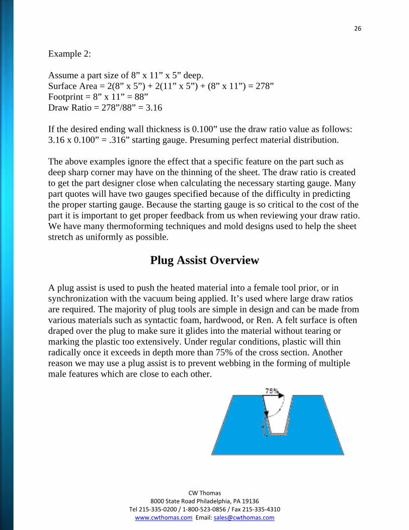
A plug assist is used to push the heated material into a female tool prior, or in synchronization with the vacuum being applied. It’s used where large draw ratios are required. The majority of plug tools are simple in design and can be made from various materials such as syntactic foam, hardwood, or Ren. A felt surface is often draped over the plug to make sure it glides into the material without tearing or marking the plastic too extensively. Under regular conditions, plastic will thin radically once it exceeds in depth more than 75% of the cross section. Another reason we may use a plug assist is to prevent webbing in the forming of multiple male features which are close to each other.
27
CW Thomas 8000 State Road Philadelphia, PA 19136
Tel 215‐335‐0200 / 1‐800‐523‐0856 / Fax 215‐335‐4310 www.cwthomas.com Email: [email protected]
Draft Angles
Overview: The control for draft is created by the coefficient of thermal expansion of the plastic. As the part is held in the mold it is cooled below the set temperature. This temperature change can be anywhere from 100 to 300 degrees ºF (37 - 149°C) depending on the resin. This change in temperature combined with the coefficient of thermal expansion will cause the part to shrink. Draft also allows for better material distribution by opening up a corner area to allow clearance for a plug assist to distribute material. Recommendations: Parts that are formed into a female mold with a texture, allow 1 degree of draft plus 1 degree of draft for every .001” of texture depth. In general, parts formed over a male mold should allow a 2 degree draft minimum and female tools are primarily controlled by its texturing surface. Details: Polymers can be thermoformed with little or no draft. However, there is high likelihood that the part will not release from the mold or will have severe scuffing from any texture that is on the mold. By designing draft into the part it is able to release from the mold much sooner in the release cycle. The greater the draft the quicker the release and the lower the chance of the part hanging up or incurring scuffing. Draft also opens up a corner and allows for a better draw ratio. The drafted wall also allow for a plug assist to move material down into the mold. Almost every plastic molding process requires draft. In thermoforming the advantage of a one sided molding process becomes apparent with draft. In a female mold the material wants to shrink away from the sidewall of the mold. In this example the shrink of the part actually assists in keeping the draft requirement to a minimum. On a male mold the part shrinks tighter on the mold making the draft requirement greater. A texture on the mold is actually a chain of undercuts in the mold. The deeper the texture, the greater the undercut and the greater the draft angle that will be required to achieve it. Because on female molds the part shrinks away from the mold there is less chance the part will scuff during release. To reiterate, any draft is better than no draft at all and the larger the draft angle, the better.
28
CW Thomas 8000 State Road Philadelphia, PA 19136
Tel 215‐335‐0200 / 1‐800‐523‐0856 / Fax 215‐335‐4310 www.cwthomas.com Email: [email protected]
Radii & Chamfers
Overview: An additional variable to consider for good part design in thermoforming is understanding the requirements for a proper size radius or chamfer. These features are needed to provide part strength, maintain material thickness, and/or esthetics. Recommendations: Try to avoid a sharp three-sided corner by using a radius or chamfer. The radius at the bottom of the draw is most important. The deeper the part the larger the radius or chamfer required. Details: One of the most difficult features to work with in thermoforming is the three-sided sharp corner in a female mold. This feature increases the draw ratio because it forces the material over the three walls as it is pushed into the corner. The material stretches and thins out usually causing the material to either thin to an unacceptable ending gauge or actually tear and create a hole in the part. An easy way to verify if this condition is occurring is to hold a part up to a light source and inspect the corners to see if the gauge is so thin that light can be transmitted through the part. A common design technique is to use radii and/or chamfers on the part, preventing the material from having to continue deeper into the corner, therefore stopping the thinning that would normally occur. The other advantage of radii and chamfers is that they distribute stress over a larger area than a sharp 90 degree corner. A chamfer does not distribute the stress as efficient as a radius, but it gives the option of sharp corners at the transition points of the chamfer. Where a three-sided corner does occur, one large radius with a chamfer or smaller radius on the other edges is often good enough to fix the thinning and strength problems that happen. As the draw ratio gets larger the radii will almost always have to be increased. Depth/Radii 0” – 3” / .015” - .125” 3” – 6” / .125” - .250” 6” and greater / minimum .250”
29
CW Thomas 8000 State Road Philadelphia, PA 19136
Tel 215‐335‐0200 / 1‐800‐523‐0856 / Fax 215‐335‐4310 www.cwthomas.com Email: [email protected]
Undercuts Overview: Undercuts are a feature that can be added to thermoformed parts. Undercuts offer increased part strength, a fastening point, a locating edge, and/or the ability to hide a trimmed edge. Tooling costs will increase, but not nearly the amount it would be if it were a structural foam molding tool or injection molding. Recommendations: When designing try to keep the distance that the undercut forms into the part to a minimum. A secondary draw ratio is used to define the starting material required to achieve the thickness of the undercut. The part will be limited to the size and thickness of the undercut based on feature locations throughout the part. Details: Usually most undercuts are an inward facing flange. However, other types of undercuts might include a reverse drafted wall, a molded in countersink or a design line that is not parallel to the direction of pull out of the mold. These features increase the surface area of the part and in turn increase the draw ratio of the part. A common request is to carry an undercut flange into one or all four corners of a part. The problem this presents is that it causes the material to stretch even more in an area that is typically the thinnest on the part, if it is a female tool. By stepping the undercut back in the corners you allow for easier material distribution. There are a few undercuts that don’t require the mold to be collapsible or removable. The undercut may be small enough or the material may be flexible enough to allow the part to release out of the mold. This is more likely to occur on a female mold because the part will shrink away from the sidewalls of the tool, rather than a male mold which finds the material shrinking tighter around it. If the undercut requires a moving section in the mold you must allow for a parting or witness line on the part. This is not normally a problem on an undercut, which is an inward facing flange, since the parting line can be hidden at the point at which the part turns in. However, on other undercuts there needs to be an excess for the parting line. Many times the parting line is used as a point of separation between a textured and un-textured surface. The safest way to integrate an undercut in the mold is with a movable section. In the past removable loose pieces have been used
30
CW Thomas 8000 State Road Philadelphia, PA 19136
Tel 215‐335‐0200 / 1‐800‐523‐0856 / Fax 215‐335‐4310 www.cwthomas.com Email: [email protected]
and placed back in the mold once they were unbound from the part preceding the next shot. Due to the risk of tool damage because of improper alignment or the harm of a textured surface, the best long term method is to integrate the articulation of the undercut section with the controls of the forming machine so that it may operate autonomously without human error.
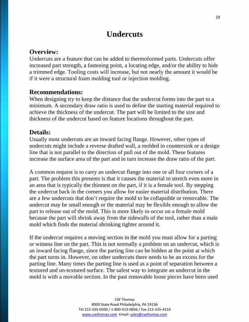
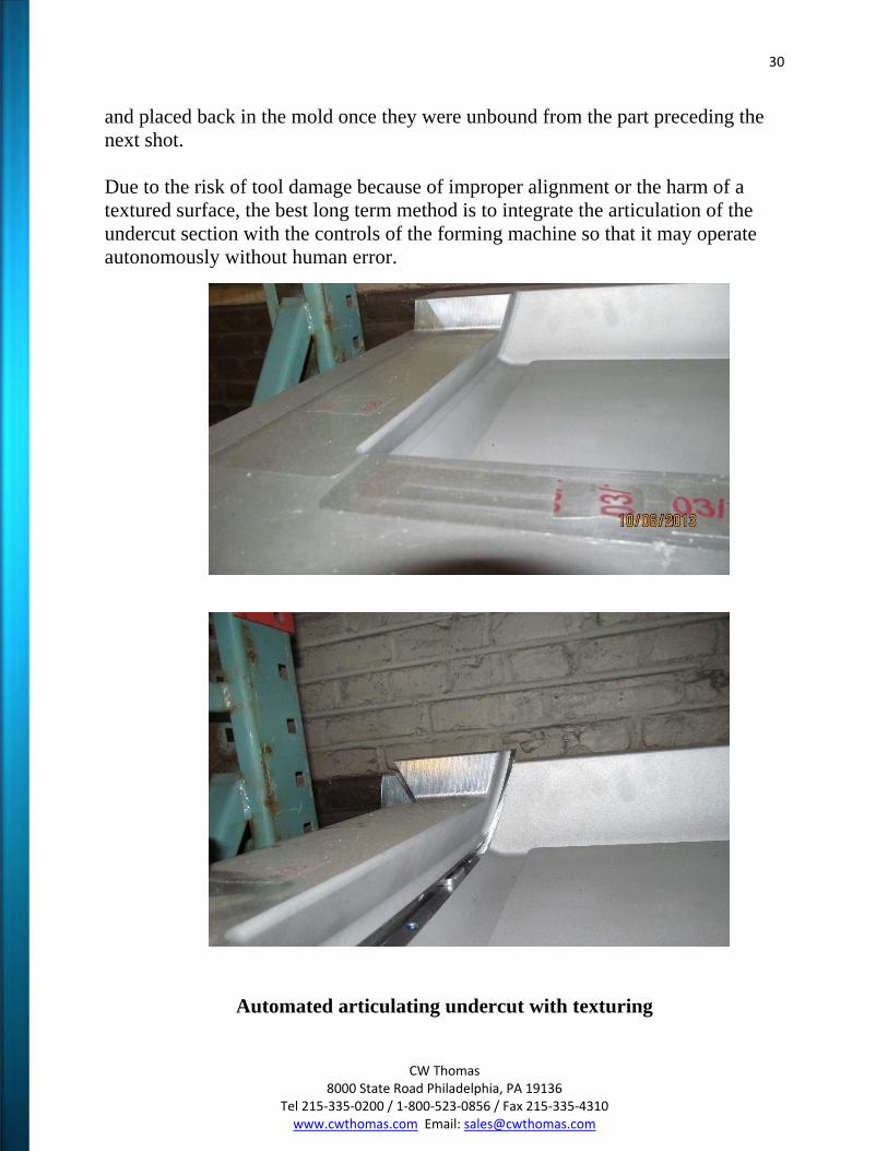
Automated articulating undercut with texturing
31
CW Thomas 8000 State Road Philadelphia, PA 19136
Tel 215‐335‐0200 / 1‐800‐523‐0856 / Fax 215‐335‐4310 www.cwthomas.com Email: [email protected]
Textures
Overview: Texture has a direct effect on the ability of the mold to evacuate the air between the sheet and the mold during the forming cycle. Some textures will actually trap air causing voids in the texture of the part. There are many texture patterns available which are formable based on your needs. Recommendations: The finer textures that are .002” or less are more difficult to form. Coarser textures allow for better replication and they also cover many mold or sheet flaws. Details: When the air is evacuated between the mold and sheet there is a need for a path for the air to move away. When the sheet touches the mold the air is trapped and needs a path to move toward vacuum holes. In the example of a texture that is designed to emulate a splatter paint finish, the mold will actually have on its surface a series of small recesses that, once the material covers them, will not allow the air to escape. Because of the trapped air, the sheet will not conform to the textured recess and the part will have a flat or poorly defined surface. The best texture would be a continuous pattern of interconnecting ridges or recesses. This pattern allows for the air to move along a path to a nearby vacuum hole. When using a cast aluminum mold, it has a rougher surface finish and usually a coarser pattern is required to cover up those imperfections. The size of the vacuum holes will also determine the type of texture required. A .040” hole with a .003” deep texture will be noticeable. Typical evacuation holes are .015” to .035”. Very fine textures with depths of .002” or less will highlight holes of this size.
32
CW Thomas 8000 State Road Philadelphia, PA 19136
Tel 215‐335‐0200 / 1‐800‐523‐0856 / Fax 215‐335‐4310 www.cwthomas.com Email: [email protected]
Ribs and Louvers (Stiffening Elements and Vents) Overview: The capability of the material to form into the recesses created by the mold will decide the dimensioning of the ribs or louvers. Recommendations: The distance between each rib and louver should be greater than or equal to its depth. Details: The cost advantages of having the thinnest acceptable wall thickness are worth paying attention to. One way of achieving increased rigidity while keeping the nominal wall thickness to a minimum is the use of shapes that provide a stiffening effect. Usually the edges of these ribs have multiple radii in order to minimize thinning out of the material as it stretched into the rib. The shape and location of stiffening ribs can be designed in various ways to fulfil the requirements of the part. This type of ribbing can be used to add crush strength to a part. It is also clear that all types of stiffening ribs could be added to increase reinforcement to a thin wall product.
33
CW Thomas 8000 State Road Philadelphia, PA 19136
Tel 215‐335‐0200 / 1‐800‐523‐0856 / Fax 215‐335‐4310 www.cwthomas.com Email: [email protected]
Fastening
Overview: Fastening is one of the most difficult subjects to resolve in the design of thermoformed parts. This is because it is not possible to mold in a boss or insert without it being visible on both sides of the part. Recommendations: Thermoforming allows for molded in bosses or inserts. Many different types of fasteners are available to be added to the part during, or after molding and trimming. Details: Molded in inserts is one of the most cost effective ways of installing fasteners because the molding process does all the work. The only added cost is for the insert. The part will take just as long to form whether there is an insert in it or not. The sheet acts as the bond that locks in the fastener. There is no need for glue or sonic welding of the insert. The use of bonded PVC blocks with a brass insert can also be prepared. The cost of the PVC, the labor to bond it in place, the cost of the adhesive, the labor to machine the block to the correct height and add a hole for the fastener or insert, all are substantial. You must then consider this with a greater probability of a lower yield rate due to the number of additional operations. The ease of a molded in insert has tangible benefits. There are a various amount fasteners that work well with thermoformed parts.

34
CW Thomas 8000 State Road Philadelphia, PA 19136
Tel 215‐335‐0200 / 1‐800‐523‐0856 / Fax 215‐335‐4310 www.cwthomas.com Email: [email protected]
Conclusion
CW Thomas would like to thank you for taking this time to learn the processes involved in Vacuum and Pressure forming. It gives us great pride to work with clients and those who have the ability of designing and controlling the variables associated with these types of thermoforming. We are always available to call and assist you with any questions that you may have. Always consider CW Thomas to be an accommodating team member of your design process.
35
CW Thomas 8000 State Road Philadelphia, PA 19136
Tel 215‐335‐0200 / 1‐800‐523‐0856 / Fax 215‐335‐4310 www.cwthomas.com Email: [email protected]
This Terms of Use Agreement sets forth the standards of use of the CW THOMAS online guide. By using the CW THOMAS guide (the "Member") agree to these terms and conditions. If you do not agree to the terms and conditions of this agreement, you should immediately cease all usage of this guide. We reserve the right, at any time, to modify, alter, or update the terms and conditions of this agreement without prior notice. Modifications shall become effective immediately upon being posted CW THOMAS cwthomas.com website. Your continued use of the Service after amendments are posted constitutes an acknowledgement and acceptance of the Agreement and its modifications. Except as provided in this paragraph, this Agreement may not be amended.
Disclaimer of Warranties
The guide is provided by CW THOMAS on an "as is" and on an "as available" basis. To the fullest extent permitted by applicable law, CW THOMAS makes no representations or warranties of any kind, express or implied, regarding the use or the results of this web site in terms of its correctness, accuracy, reliability, or otherwise. CW THOMAS shall have no liability for any interruptions in the use of this Website. CW THOMAS disclaims all warranties with regard to the information provided, including the implied warranties of merchantability and fitness for a particular purpose, and non-infringement. Some jurisdictions do not allow the exclusion of implied warranties, therefore the above-referenced exclusion is inapplicable.
Limitation of Liability
CW THOMAS SHALL NOT BE LIABLE FOR ANY DAMAGES WHATSOEVER, AND IN PARTICULAR CW THOMAS SHALL NOT BE LIABLE FOR ANY SPECIAL, INDIRECT, CONSEQUENTIAL, OR INCIDENTAL DAMAGES, OR DAMAGES FOR LOST PROFITS, LOSS OF REVENUE, OR LOSS OF USE, ARISING OUT OF OR RELATED TO THIS GUIDE OR THE INFORMATION CONTAINED IN IT, WHETHER SUCH DAMAGES ARISE IN CONTRACT, NEGLIGENCE, TORT, UNDER STATUTE, IN EQUITY, AT LAW, OR OTHERWISE, EVEN IF CW THOMAS HAS BEEN ADVISED OF THE POSSIBILITY OF SUCH DAMAGES. SOME JURISDICTIONS DO NOT ALLOW FOR THE LIMITATION OR EXCLUSION OF LIABILITY FOR INCIDENTAL OR CONSEQUENTIAL DAMAGES, THEREFORE SOME OF THE ABOVE LIMITATIONS IS INAPPLICABLE.
Indemnification
Member agrees to indemnify and hold CW THOMAS, its parents, subsidiaries, affiliates, officers and employees, harmless from any claim or demand, including reasonable attorneys' fees and costs, made by any third party due to or arising out of Member's use of the Service, the violation of this Agreement, or infringement by Member, or other user of the Service using Member's computer, of any intellectual property or any other right of any person or entity.
Disclaimer Regarding Accuracy of Vendor Information
Product specifications and other information have either been provided by the Vendors or collected from publicly available sources. While CW THOMAS makes every effort to ensure that the information on this website is accurate, we can make no representations or warranties as to the accuracy or reliability of any information provided on this website.
CW THOMAS makes no warranties or representations whatsoever with regard to any product provided or offered by any Vendor, and you acknowledge that any reliance on representations and warranties provided by any Vendor shall be at your own risk.