THERMOELASTIC STRESS ANALYSIS FOR STRUCTURAL PERFORMANCE ... · THERMOELASTIC STRESS ANALYSIS FOR...
7
21 st International Conference on Composite Materials Xi’an, 20-25 th August 2017 THERMOELASTIC STRESS ANALYSIS FOR STRUCTURAL PERFORMANCE ASSESSMENT OF AEROSPACE COMPOSITES Nik Rajic 1 , Chris Brooks 1 , John Wang 1 , Crystal Forrester 1 and Geoff Swanton 1 1 Defence Science and Technology Group, [email protected] Keywords: Aerospace, full scale testing, composites, thermoelastic stress analysis, microbolometers ABSTRACT The development of thermoelastic stress analysis systems employing compact low-cost thermal detectors provides an important capability for aircraft structural integrity assurance. In aircraft full- scale durability testing it affords a significantly improved basis for validating finite element modelling of complex airframe components, and can be used to rapidly identify and then monitor fatigue hot spots. To date such systems have mostly been applied to metallic aircraft components and on issues relating primarily to fatigue, however with the growing use of composite materials in aircraft there is interest in how these systems can be applied to composite aircraft components. This paper draws on several case studies from coupon level to full-scale airframe fatigue testing to demonstrate that thermal detector based TSA systems can play an important role in evaluating the structural performance of composite aircraft components. 1 INTRODUCTION Thermoelastic Stress Analysis (TSA) is an established experimental stress imaging technique that infers bulk stress from radiometric measurements of temperature via the thermoelastic effect; a phenomenon that describes a reversible coupling between dilatational deformation and temperature in solids [1]. The method has been applied to the study of composite materials for well over 30 years but in a limited way and primarily as a research tool. The reasons for this are manifold and varied. One factor is the difficulty in extracting components of stress (or strain) from bulk stress. This is an issue for both metals and composites but is most acute for the latter due to the added complexity of directional material properties and the strong through-thickness heat diffusion induced by inter- laminar stress discontinuity in laminates with multi-directional layup. By contrast, digital image correlation, a better known and more widely used full-field strain measurement technique, yields component field values by default. Another factor is the traditionally high cost of commercial TSA instrumentation which can be traced to a reliance on cryogenically-cooled infrared detectors, a highly sensitive but relatively expensive imaging technology. Recent developments warrant a re-examination of these issues. Firstly, the affordability and practicality of TSA hardware has improved dramatically. This follows the recent development of thermal detector based TSA systems which are significantly more compact, rugged and affordable. Moreover, such systems produce comparable, and in some circumstances superior, stress-image quality to cooled detectors [2]. The practical implications for TSA are significant and nowhere more so than in the aerospace sector where these small rugged low-cost thermal detectors have enabled TSA to applied to important aircraft structural integrity problems. In situ stress surveys of structural test airframes are now routine at the Australian Defence Science and Technology (DST) Group, and recently the approach was applied to several F-35 durability test airframes with excellent results [3]. Such surveys have provided unprecedented insights for structural finite element model validation, and other applications in airframe testing are now being explored [4]. The other key development is the emergence of Multiphysics simulation as a widely accessible computational tool. This capability has made it possible to better understand the effect of ply lay-up and loading rate on the thermoelastic response of multi-layered composites.
-
Upload
trinhthuan -
Category
Documents
-
view
233 -
download
0
Transcript of THERMOELASTIC STRESS ANALYSIS FOR STRUCTURAL PERFORMANCE ... · THERMOELASTIC STRESS ANALYSIS FOR...

21st International Conference on Composite Materials
Xi’an, 20-25th
August 2017
THERMOELASTIC STRESS ANALYSIS FOR STRUCTURAL
PERFORMANCE ASSESSMENT OF AEROSPACE COMPOSITES
Nik Rajic1, Chris Brooks1, John Wang1, Crystal Forrester1 and Geoff Swanton1
1 Defence Science and Technology Group, [email protected]
Keywords: Aerospace, full scale testing, composites, thermoelastic stress analysis, microbolometers
ABSTRACT
The development of thermoelastic stress analysis systems employing compact low-cost thermal
detectors provides an important capability for aircraft structural integrity assurance. In aircraft full-
scale durability testing it affords a significantly improved basis for validating finite element modelling
of complex airframe components, and can be used to rapidly identify and then monitor fatigue hot spots. To date such systems have mostly been applied to metallic aircraft components and on issues
relating primarily to fatigue, however with the growing use of composite materials in aircraft there is
interest in how these systems can be applied to composite aircraft components. This paper draws on
several case studies from coupon level to full-scale airframe fatigue testing to demonstrate that thermal
detector based TSA systems can play an important role in evaluating the structural performance of
composite aircraft components.
1 INTRODUCTION
Thermoelastic Stress Analysis (TSA) is an established experimental stress imaging technique that
infers bulk stress from radiometric measurements of temperature via the thermoelastic effect; a
phenomenon that describes a reversible coupling between dilatational deformation and temperature in
solids [1]. The method has been applied to the study of composite materials for well over 30 years but
in a limited way and primarily as a research tool. The reasons for this are manifold and varied. One
factor is the difficulty in extracting components of stress (or strain) from bulk stress. This is an issue
for both metals and composites but is most acute for the latter due to the added complexity of
directional material properties and the strong through-thickness heat diffusion induced by inter-
laminar stress discontinuity in laminates with multi-directional layup. By contrast, digital image
correlation, a better known and more widely used full-field strain measurement technique, yields
component field values by default. Another factor is the traditionally high cost of commercial TSA
instrumentation which can be traced to a reliance on cryogenically-cooled infrared detectors, a highly
sensitive but relatively expensive imaging technology.
Recent developments warrant a re-examination of these issues. Firstly, the affordability and practicality of TSA hardware has improved dramatically. This follows the recent development of
thermal detector based TSA systems which are significantly more compact, rugged and affordable.
Moreover, such systems produce comparable, and in some circumstances superior, stress-image
quality to cooled detectors [2]. The practical implications for TSA are significant and nowhere more
so than in the aerospace sector where these small rugged low-cost thermal detectors have enabled TSA
to applied to important aircraft structural integrity problems. In situ stress surveys of structural test
airframes are now routine at the Australian Defence Science and Technology (DST) Group, and recently the approach was applied to several F-35 durability test airframes with excellent results [3].
Such surveys have provided unprecedented insights for structural finite element model validation, and
other applications in airframe testing are now being explored [4]. The other key development is the
emergence of Multiphysics simulation as a widely accessible computational tool. This capability has
made it possible to better understand the effect of ply lay-up and loading rate on the thermoelastic
response of multi-layered composites.
N. Rajic, C. Brooks, J. Wang, C. Forrester and G. Swanton
This paper focuses primarily on the first issue, that of affordability and practicality. Three case
studies are presented involving aircraft structural integrity support activities at DST. These are used to
illustrate how the use of thermal detectors has enhanced the role TSA can play in evaluating the structural performance of composite aircraft components. The case studies are introduced in order of
test complexity starting with a relatively simple coupon test and ending with two full-scale airframe
fatigue tests.
2 COUPON LEVEL – ASSESSMENT OF REPAIRS TO LIGHTWEIGHT COMPOSITE
AIRCRAFT STRUCTURE
The issue of composite impact vulnerability is particularly acute for military helicopter operation
where impact threats are many. In addition to conventional threats like bird strike and tool drop there
are uniquely military hazards such as shell-casing ejection and troop embarkation. Bonded repair is
often the most efficient approach to restoring strength in the event of impact damage.
doubler
cut
doubleroverlaplength
Nomexcore
skin
X component Y component
0.5 Hz
2 Hz
5 Hz
10 Hz
cut
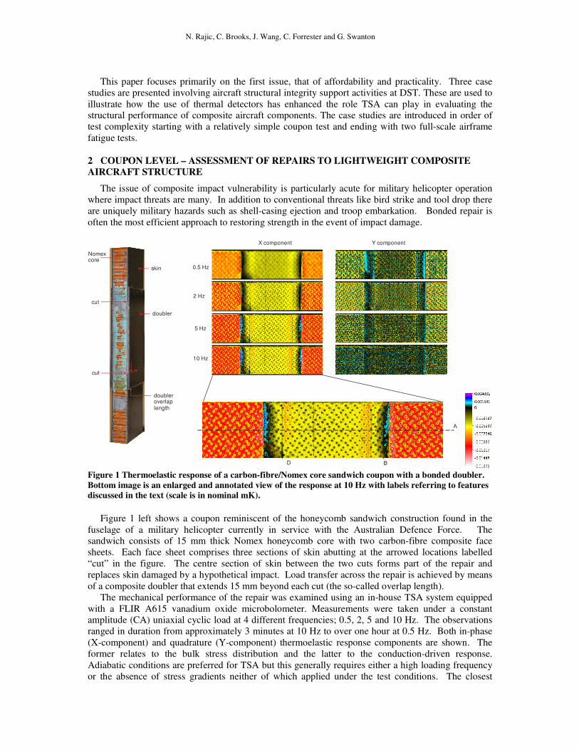
Figure 1 Thermoelastic response of a carbon-fibre/Nomex core sandwich coupon with a bonded doubler.
Bottom image is an enlarged and annotated view of the response at 10 Hz with labels referring to features
discussed in the text (scale is in nominal mK).
Figure 1 left shows a coupon reminiscent of the honeycomb sandwich construction found in the
fuselage of a military helicopter currently in service with the Australian Defence Force. The sandwich consists of 15 mm thick Nomex honeycomb core with two carbon-fibre composite face
sheets. Each face sheet comprises three sections of skin abutting at the arrowed locations labelled
“cut” in the figure. The centre section of skin between the two cuts forms part of the repair and
replaces skin damaged by a hypothetical impact. Load transfer across the repair is achieved by means
of a composite doubler that extends 15 mm beyond each cut (the so-called overlap length).
The mechanical performance of the repair was examined using an in-house TSA system equipped
with a FLIR A615 vanadium oxide microbolometer. Measurements were taken under a constant amplitude (CA) uniaxial cyclic load at 4 different frequencies; 0.5, 2, 5 and 10 Hz. The observations
ranged in duration from approximately 3 minutes at 10 Hz to over one hour at 0.5 Hz. Both in-phase
(X-component) and quadrature (Y-component) thermoelastic response components are shown. The
former relates to the bulk stress distribution and the latter to the conduction-driven response.
Adiabatic conditions are preferred for TSA but this generally requires either a high loading frequency
or the absence of stress gradients neither of which applied under the test conditions. The closest
21st International Conference on Composite Materials
Xi’an, 20-25th
August 2017
approximation in the present situation was achieved at 10 Hz which is confirmed by the uniformly low
quadrature response in the Figure (black corresponds to a null response). An enlarged view of this
scan, shown at the bottom of the figure, identifies four features of interest (labelled A-D) for discussion in the next paragraph.
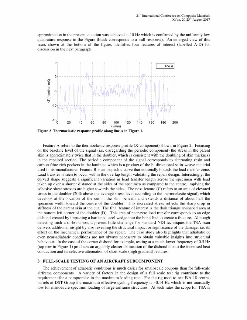
0 20 40 60 80 100 120 140 160 180 200-15
-10
-5
0
5
x (mm)
∆T
(n
om
ina
l m
K)
line A
Figure 2 Thermoelastic response profile along line A in Figure 1.
Feature A refers to the thermoelastic response profile (X-component) shown in Figure 2. Focusing
on the baseline level of the signal (i.e. disregarding the periodic component) the stress in the parent
skin is approximately twice that in the doubler, which is consistent with the doubling of skin thickness
in the repaired section. The periodic component of the signal corresponds to alternating resin and
carbon-fibre rich pockets in the laminate which is a product of the bi-directional satin-weave material
used in its manufacture. Feature B is an isopachic curve that notionally bounds the load transfer zone.
Load transfer is seen to occur within the overlap length validating the repair design. Interestingly, the
curved shape suggests a significant variation in load transfer length across the specimen with load
taken up over a shorter distance at the sides of the specimen as compared to the centre, implying the
adhesive shear stresses are higher towards the sides. The next feature (C) refers to an area of elevated
stress in the doubler (20% above the average stress level according to the thermoelastic signal) which
develops at the location of the cut in the skin beneath and extends a distance of about half the
specimen width toward the centre of the doubler. This increased stress reflects the sharp drop in stiffness of the parent skin at the cut. The final feature of interest is the dark triangular-shaped area at
the bottom left corner of the doubler (D). This area of near-zero load transfer corresponds to an edge
disbond created by impacting a hardened steel wedge into the bond-line to create a fracture. Although
detecting such a disbond would present little challenge for standard NDI techniques the TSA scan
delivers additional insight by also revealing the structural impact or significance of the damage, i.e. its
effect on the mechanical performance of the repair. The case study also highlights that adiabatic or
even near-adiabatic conditions are not always necessary to obtain valuable insights into structural behaviour. In the case of the corner disbond for example, testing at a much lower frequency of 0.5 Hz
(top row in Figure 1) produces an arguably clearer delineation of the disbond due to the increased heat
conduction and its selective attenuation of short-scale (high gradient) features.
3 FULL-SCALE TESTING OF AN AIRCRAFT SUBCOMPONENT
The achievement of adiabatic conditions is much easier for small-scale coupons than for full-scale
airframe components. A variety of factors in the design of a full scale test rig contribute to the requirement for a compromise in the maximum loading rate. For the rig used to test F/A-18 centre-
barrels at DST Group the maximum effective cycling frequency is ~0.14 Hz which is not unusually
low for manoeuvre spectrum loading of large airframe structures. At such rates the scope for TSA is
N. Rajic, C. Brooks, J. Wang, C. Forrester and G. Swanton
quite limited as a result of signal attenuation and phase shift due to heat diffusion. Fortunately, by
restricting peak loads to a fraction of the maximum spectrum load and maintaining a constant
amplitude much higher frequencies can be achieved; 1 Hz in the case of the F/A-18 centre-barrel test program. This approach has enabled detailed study of many different aspects of centre-barrel
structural performance, including assessment of the effect and performance of repairs and
reinforcements. One such study involved a boron-epoxy doubler designed by the Finnish Air Force to
extend the fatigue life of a critical section of the lower flange of the rear bulkhead [5].
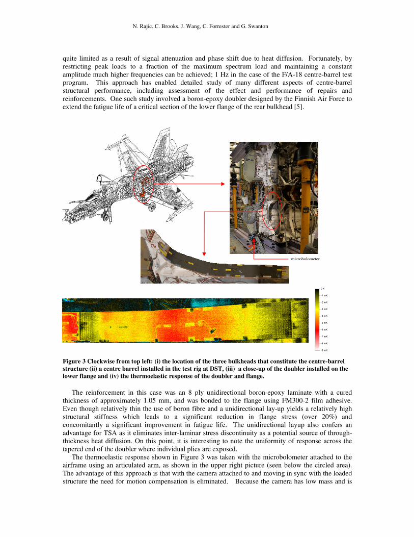
Figure 3 Clockwise from top left: (i) the location of the three bulkheads that constitute the centre-barrel
structure (ii) a centre barrel installed in the test rig at DST, (iii) a close-up of the doubler installed on the
lower flange and (iv) the thermoelastic response of the doubler and flange.
The reinforcement in this case was an 8 ply unidirectional boron-epoxy laminate with a cured
thickness of approximately 1.05 mm, and was bonded to the flange using FM300-2 film adhesive.
Even though relatively thin the use of boron fibre and a unidirectional lay-up yields a relatively high
structural stiffness which leads to a significant reduction in flange stress (over 20%) and
concomitantly a significant improvement in fatigue life. The unidirectional layup also confers an
advantage for TSA as it eliminates inter-laminar stress discontinuity as a potential source of through-
thickness heat diffusion. On this point, it is interesting to note the uniformity of response across the
tapered end of the doubler where individual plies are exposed.
The thermoelastic response shown in Figure 3 was taken with the microbolometer attached to the
airframe using an articulated arm, as shown in the upper right picture (seen below the circled area).
The advantage of this approach is that with the camera attached to and moving in sync with the loaded
structure the need for motion compensation is eliminated. Because the camera has low mass and is
-9 mK
0 K
-8 mK
-7 mK
-6 mK
-5 mK
-4 mK
-3 mK
-2 mK
-1 mK
microbolometer
21st International Conference on Composite Materials
Xi’an, 20-25th
August 2017
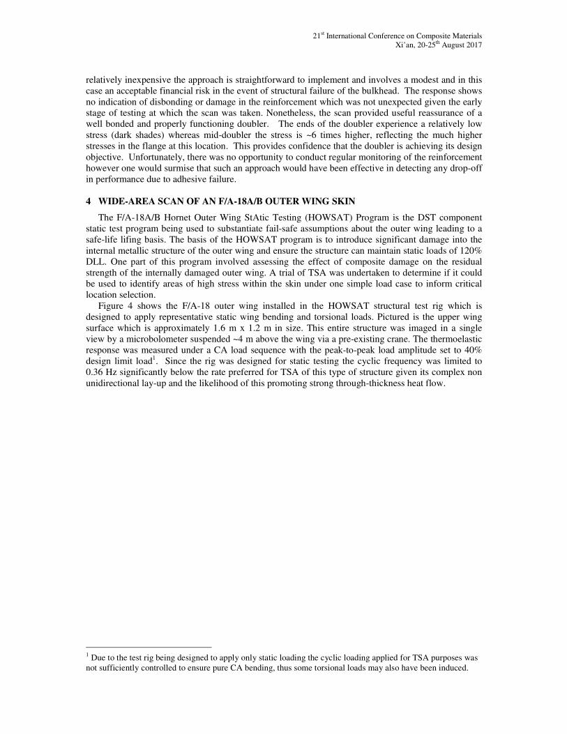
relatively inexpensive the approach is straightforward to implement and involves a modest and in this
case an acceptable financial risk in the event of structural failure of the bulkhead. The response shows
no indication of disbonding or damage in the reinforcement which was not unexpected given the early stage of testing at which the scan was taken. Nonetheless, the scan provided useful reassurance of a
well bonded and properly functioning doubler. The ends of the doubler experience a relatively low
stress (dark shades) whereas mid-doubler the stress is ~6 times higher, reflecting the much higher
stresses in the flange at this location. This provides confidence that the doubler is achieving its design
objective. Unfortunately, there was no opportunity to conduct regular monitoring of the reinforcement
however one would surmise that such an approach would have been effective in detecting any drop-off
in performance due to adhesive failure.
4 WIDE-AREA SCAN OF AN F/A-18A/B OUTER WING SKIN
The F/A-18A/B Hornet Outer Wing StAtic Testing (HOWSAT) Program is the DST component
static test program being used to substantiate fail-safe assumptions about the outer wing leading to a
safe-life lifing basis. The basis of the HOWSAT program is to introduce significant damage into the
internal metallic structure of the outer wing and ensure the structure can maintain static loads of 120%
DLL. One part of this program involved assessing the effect of composite damage on the residual
strength of the internally damaged outer wing. A trial of TSA was undertaken to determine if it could
be used to identify areas of high stress within the skin under one simple load case to inform critical
location selection.
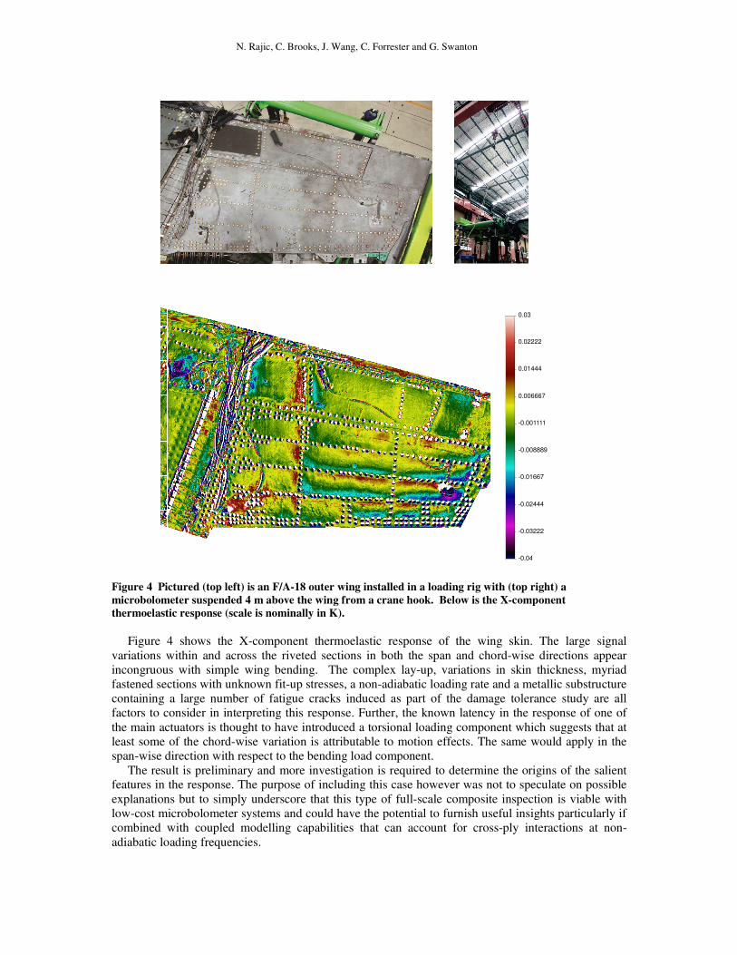
Figure 4 shows the F/A-18 outer wing installed in the HOWSAT structural test rig which is
designed to apply representative static wing bending and torsional loads. Pictured is the upper wing
surface which is approximately 1.6 m x 1.2 m in size. This entire structure was imaged in a single
view by a microbolometer suspended ~4 m above the wing via a pre-existing crane. The thermoelastic
response was measured under a CA load sequence with the peak-to-peak load amplitude set to 40%
design limit load1. Since the rig was designed for static testing the cyclic frequency was limited to
0.36 Hz significantly below the rate preferred for TSA of this type of structure given its complex non
unidirectional lay-up and the likelihood of this promoting strong through-thickness heat flow.
1 Due to the test rig being designed to apply only static loading the cyclic loading applied for TSA purposes was
not sufficiently controlled to ensure pure CA bending, thus some torsional loads may also have been induced.
N. Rajic, C. Brooks, J. Wang, C. Forrester and G. Swanton
Figure 4 Pictured (top left) is an F/A-18 outer wing installed in a loading rig with (top right) a
microbolometer suspended 4 m above the wing from a crane hook. Below is the X-component
thermoelastic response (scale is nominally in K).
Figure 4 shows the X-component thermoelastic response of the wing skin. The large signal
variations within and across the riveted sections in both the span and chord-wise directions appear
incongruous with simple wing bending. The complex lay-up, variations in skin thickness, myriad
fastened sections with unknown fit-up stresses, a non-adiabatic loading rate and a metallic substructure
containing a large number of fatigue cracks induced as part of the damage tolerance study are all
factors to consider in interpreting this response. Further, the known latency in the response of one of
the main actuators is thought to have introduced a torsional loading component which suggests that at
least some of the chord-wise variation is attributable to motion effects. The same would apply in the
span-wise direction with respect to the bending load component.
The result is preliminary and more investigation is required to determine the origins of the salient features in the response. The purpose of including this case however was not to speculate on possible
explanations but to simply underscore that this type of full-scale composite inspection is viable with
low-cost microbolometer systems and could have the potential to furnish useful insights particularly if
combined with coupled modelling capabilities that can account for cross-ply interactions at non-
adiabatic loading frequencies.
-0.04
0.03
-0.03222
-0.02444
-0.01667
-0.008889
-0.001111
0.006667
0.01444
0.02222
21st International Conference on Composite Materials
Xi’an, 20-25th
August 2017
5 CONCLUSIONS
The development of compact low-cost thermoelastic stress analysis instrumentation affords
increased opportunity to apply TSA to the structural evaluation of composites. This paper has used case studies in simple coupon testing and full-scale airframe fatigue test programs to underscore the
engineering value of thermoelastic response measurements and to demonstrate how these new
compact low-cost systems can facilitate the application of TSA to large scale airframe testing.
ACKNOWLEDGEMENTS
The authors are grateful to Peter Lombardo for his assistance in preparing the coupon described in
section 2, and to Peter Smith & Leigh Robertson for operating the full scale fatigue test rigs referred to
in this article.
REFERENCES
[1] G. Pitarresi and E. A. Patterson, A review of the general theory of thermoelastic stress analysis.
The Journal of Strain Analysis for Engineering Design, 38, 2003, pp. 405–17.
[2] N. Rajic and N. Street, A Performance Comparison Between Cooled and Uncooled Infrared
Detectors for Thermoelastic Stress Analysis, Quantitative Infrared Thermography Journal,
2014, doi: 10.1080/17686733.2014.962835.
[3] N. Rajic, D. McSwiggen, M. McDonald, and D. Whiteley, In situ thermoelastic stress analysis
of the F-35 - an improved approach to airframe structural model validation, Proc. Aircraft
Structural Integrity Program Conference, Dec 1-3, 2015.
http://www.meetingdata.utcdayton.com/agenda/asip/2015/proceedings/presentations/P8675.pdf
(accessed 15 May 2017).
[4] N. Rajic and S. Galea, Thermoelastic Stress Analysis and Structural Health Monitoring: An
Emerging Nexus, Structural Health Monitoring, 2014, doi: 10.1177/1475921714548936.
[5] G. Swanton, M. Keinonen and J. Linna, Full-Scale Fatigue Testing of a Boron-Epoxy Bonded
Doubler for the Finnish Air Force F/A-18 Hornet Centre Fuselage, Proceedings of the 28th ICAF
Symposium, Helsinki, 3-5 June 2015.
[6] R. T. Potter, Stress Analysis in Laminated Fibre Composites by Thermoelastic Emissions,
Stress Analysis by Thermoelastic Techniques, 1987, pp. 110-120.