Thermocouples & RTD’s - General Information · Thermocouples & RTD’s - General Information...
14
7925 N. Clinton St., Fort Wayne, IN 46825 USA • Web: www.servicesforplastics.com • E-mail: [email protected] Toll Free Phone: 800-627-1033 • Fax: 800-482-4059 • Local Phone: 260-482-9211 • Fax: 260-483-8139 14J Thermocouples & RTD’s - General Information Thermocouples A thermocouple is a temperature measuring device consisting of two conductors of dissimilar metals or alloys that are connected only at the ends. When the ends are at different temperatures, a small voltage is produced in the wire that can be related directly to the temperature difference between the ends. If the temperature at one end is known, the temperature at the other end can be determined. Thermocouple wire or extension grade wire is used to connect the thermocouple to the sensing or control instrumentation. The conditions of measurement determine the type of thermocouple wire and insulation to be used. Temperature range, environment, insulation requirements, response, and service life should be considered when selecting a wire type. There are two common types of thermocouple wire, Type “J” and Type “K”. Type “J” (Iron/Constantan™) Type J thermocouples are used in vacuum, oxidizing, inert or reducing atmospheres. Iron element oxidizes rapidly at temperatures exceeding 1000°F (538°C), and therefore heavier gauge wire is recommended for longer life at these temperatures. Type “K” (Chromel™/Alumel™) Type K thermocouples are used in oxidizing, inert or dry reducing atmospheres. Exposure to vacuum is limited to short time periods. Must be protected from sulfurous and marginally oxidizing atmospheres. Reliable and accurate at high temperatures. GROUNDED THERMOCOUPLES The thermocouple junction is connected to the tip of the metal enclosure. Being connected to the sheath of the enclosure affords protection to the thermocouple and excellent response. UNGROUNDED THERMOCOUPLES The thermocouple is isolated from the metal sheath and for this reason gives up a little response time. By being electronically insulated, this design is not subjected to picking up electrical noise. Most newer Van Dorns, and some other machines, require ungrounded thermocouples. Other styles, sheath sizes and materials, leadwire types and thread sizes are also available. RTD’s A Resistance Temperature Detector (RTD) is a temperature sensing probe of finely wound platinum wire that displays a linear resistance increase for a corresponding temperature increase. RTD’s are built on the principle that most metals have a positive charge in electrical resistance with a change in temperature. When quality control is of extreme importance, an RTD is unequalled for accuracy and repeatability. RTD’s do not require cold junction compensation or special extension wire. RTD’s are available in two different temperature ranges and leadwire types, the “L” Series and the “M” Series. All sheaths and tips are manufactured from 316 stainless steel for superior resistance to corrosion, abrasion, and deterioration. 2-Wire Configuration A 2-wire configuration is a less accurate style of RTD assembly. The added lead wire resistance is not compensated for by the temperature controller or transmitter used to monitor the resistance of the RTD. This increased resistance will cause the display temperature to be higher than the actual temperature. 3-Wire Configuration A 3-wire configuration is the most common configuration because it is both cost effective and accurate. The added lead wire resistance is calculated by the controller through the third wire of the RTD assembly. The leadwire resistance is then subtracted from the loop resistance and true resistance is found. Through this method the controller or transmitter “compensates” the lead wire giving an accurate temperature display. Thermocouple Type Page Adjustable Depth ................................. 344 • Armor Adjustable • Spring Adjustable Fixed Bayonet & Rigid Tube ............... 345 Threaded Nozzle ................................. 346 Spade .................................................... 347 Ring ....................................................... 347 Melt Bolt ................................................ 348 • Fiberglass • MgO Thermocouple Extensions .................. 349 Pipe Clamp ............................................ 350 RTD Type Page Adjustable Depth ......... 354 Fixed Bayonet .............. 355 Rigid Tube ..................... 355
Transcript of Thermocouples & RTD’s - General Information · Thermocouples & RTD’s - General Information...
7925 N. Clinton St., Fort Wayne, IN 46825 USA • Web: www.servicesforplastics.com • E-mail: [email protected] Free Phone: 800-627-1033 • Fax: 800-482-4059 • Local Phone: 260-482-9211 • Fax: 260-483-8139
14J
Thermocouples & RTD’s - General Information
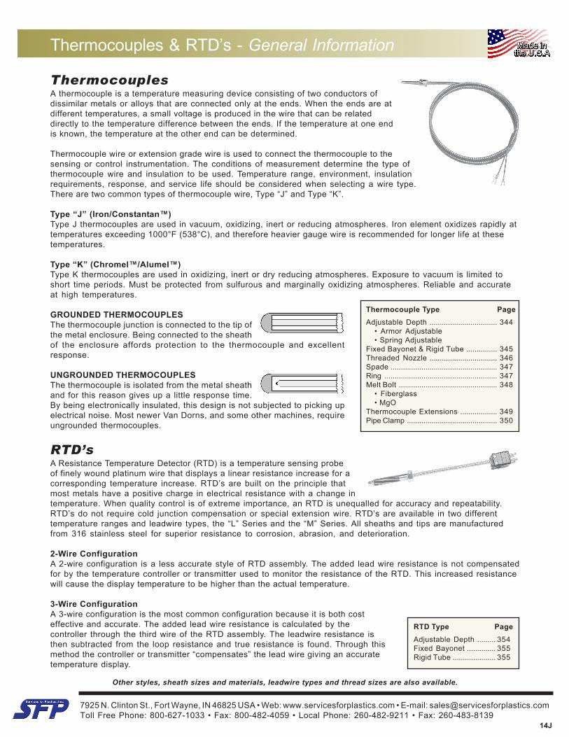
ThermocouplesA thermocouple is a temperature measuring device consisting of two conductors ofdissimilar metals or alloys that are connected only at the ends. When the ends are atdifferent temperatures, a small voltage is produced in the wire that can be relateddirectly to the temperature difference between the ends. If the temperature at one endis known, the temperature at the other end can be determined.
Thermocouple wire or extension grade wire is used to connect the thermocouple to thesensing or control instrumentation. The conditions of measurement determine the type ofthermocouple wire and insulation to be used. Temperature range, environment, insulationrequirements, response, and service life should be considered when selecting a wire type.There are two common types of thermocouple wire, Type “J” and Type “K”.
Type “J” (Iron/Constantan™)Type J thermocouples are used in vacuum, oxidizing, inert or reducing atmospheres. Iron element oxidizes rapidly attemperatures exceeding 1000°F (538°C), and therefore heavier gauge wire is recommended for longer life at thesetemperatures.
Type “K” (Chromel™/Alumel™)Type K thermocouples are used in oxidizing, inert or dry reducing atmospheres. Exposure to vacuum is limited toshort time periods. Must be protected from sulfurous and marginally oxidizing atmospheres. Reliable and accurateat high temperatures.
GROUNDED THERMOCOUPLESThe thermocouple junction is connected to the tip ofthe metal enclosure. Being connected to the sheathof the enclosure affords protection to the thermocouple and excellentresponse.
UNGROUNDED THERMOCOUPLESThe thermocouple is isolated from the metal sheathand for this reason gives up a little response time.By being electronically insulated, this design is not subjected to picking upelectrical noise. Most newer Van Dorns, and some other machines, requireungrounded thermocouples.
Other styles, sheath sizes and materials, leadwire types and thread sizes are also available.
RTD’sA Resistance Temperature Detector (RTD) is a temperature sensing probeof finely wound platinum wire that displays a linear resistance increase for acorresponding temperature increase. RTD’s are built on the principle thatmost metals have a positive charge in electrical resistance with a change intemperature. When quality control is of extreme importance, an RTD is unequalled for accuracy and repeatability.RTD’s do not require cold junction compensation or special extension wire. RTD’s are available in two differenttemperature ranges and leadwire types, the “L” Series and the “M” Series. All sheaths and tips are manufacturedfrom 316 stainless steel for superior resistance to corrosion, abrasion, and deterioration.
2-Wire ConfigurationA 2-wire configuration is a less accurate style of RTD assembly. The added lead wire resistance is not compensatedfor by the temperature controller or transmitter used to monitor the resistance of the RTD. This increased resistancewill cause the display temperature to be higher than the actual temperature.
3-Wire ConfigurationA 3-wire configuration is the most common configuration because it is both costeffective and accurate. The added lead wire resistance is calculated by thecontroller through the third wire of the RTD assembly. The leadwire resistance isthen subtracted from the loop resistance and true resistance is found. Through thismethod the controller or transmitter “compensates” the lead wire giving an accuratetemperature display.
Thermocouple Type PageAdjustable Depth ................................. 344
• Armor Adjustable• Spring Adjustable
Fixed Bayonet & Rigid Tube ............... 345Threaded Nozzle ................................. 346Spade .................................................... 347Ring ....................................................... 347Melt Bolt ................................................ 348
• Fiberglass• MgO
Thermocouple Extensions .................. 349Pipe Clamp ............................................ 350
RTD Type PageAdjustable Depth ......... 354Fixed Bayonet .............. 355Rigid Tube ..................... 355
7925 N. Clinton St., Fort Wayne, IN 46825 USA • Web: www.servicesforplastics.com • E-mail: [email protected] Free Phone: 800-627-1033 • Fax: 800-482-4059 • Local Phone: 260-482-9211 • Fax: 260-483-8139
14J
Thermocouple Wire Reference Data
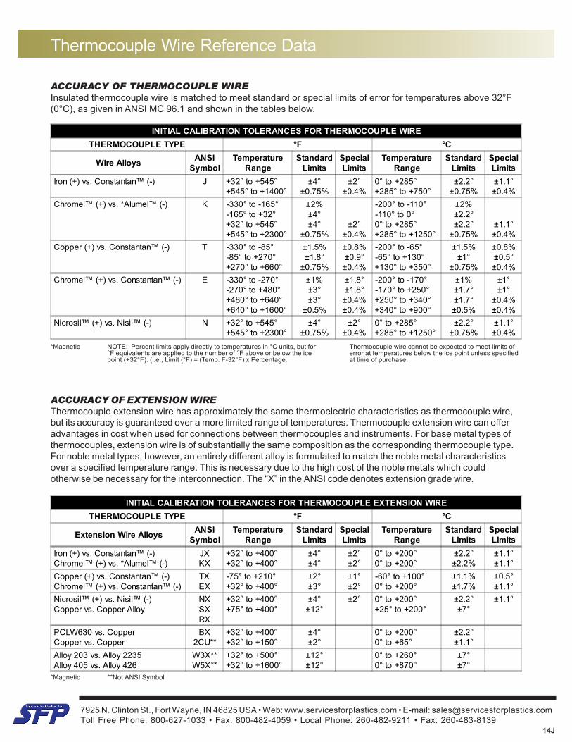
ACCURACY OF THERMOCOUPLE WIREInsulated thermocouple wire is matched to meet standard or special limits of error for temperatures above 32°F(0°C), as given in ANSI MC 96.1 and shown in the tables below.
INITIAL CALIBRATION TOLERANCES FOR THERMOCOUPLE WIRETHERMOCOUPLE TYPE °F °C
Wire Alloys ANSISymbol
TemperatureRange
StandardLimits
SpecialLimits
TemperatureRange
StandardLimits
SpecialLimits
Iron (+) vs. Constantan™ (-) J +32° to +545°+545° to +1400°
±4°±0.75%
±2°±0.4%
0° to +285°+285° to +750°
±2.2°±0.75%
±1.1°±0.4%
Chromel™ (+) vs. *Alumel™ (-) K -330° to -165°-165° to +32°+32° to +545°+545° to +2300°
±2%±4°±4°
±0.75%±2°
±0.4%
-200° to -110°-110° to 0°0° to +285°+285° to +1250°
±2%±2.2°±2.2°
±0.75%±1.1°±0.4%
Copper (+) vs. Constantan™ (-) T -330° to -85°-85° to +270°+270° to +660°
±1.5%±1.8°
±0.75%
±0.8%±0.9°±0.4%
-200° to -65°-65° to +130°+130° to +350°
±1.5%±1°
±0.75%
±0.8%±0.5°±0.4%
Chromel™ (+) vs. Constantan™ (-) E -330° to -270°-270° to +480°+480° to +640°+640° to +1600°
±1%±3°±3°
±0.5%
±1.8°±1.8°±0.4%±0.4%
-200° to -170°-170° to +250°+250° to +340°+340° to +900°
±1%±1.7°±1.7°±0.5%
±1°±1°
±0.4%±0.4%
Nicrosil™ (+) vs. Nisil™ (-) N +32° to +545°+545° to +2300°
±4°±0.75%
±2°±0.4%
0° to +285°+285° to +1250°
±2.2°±0.75%
±1.1°±0.4%
*Magnetic NOTE: Percent limits apply directly to temperatures in °C units, but for Thermocouple wire cannot be expected to meet limits of°F equivalents are applied to the number of °F above or below the ice error at temperatures below the ice point unless specifiedpoint (+32°F). (i.e., Limit (°F) = (Temp. F-32°F) x Percentage. at time of purchase.
ACCURACY OF EXTENSION WIREThermocouple extension wire has approximately the same thermoelectric characteristics as thermocouple wire,but its accuracy is guaranteed over a more limited range of temperatures. Thermocouple extension wire can offeradvantages in cost when used for connections between thermocouples and instruments. For base metal types ofthermocouples, extension wire is of substantially the same composition as the corresponding thermocouple type.For noble metal types, however, an entirely different alloy is formulated to match the noble metal characteristicsover a specified temperature range. This is necessary due to the high cost of the noble metals which couldotherwise be necessary for the interconnection. The “X” in the ANSI code denotes extension grade wire.
*Magnetic **Not ANSI Symbol
INITIAL CALIBRATION TOLERANCES FOR THERMOCOUPLE EXTENSION WIRETHERMOCOUPLE TYPE °F °C
Extension Wire Alloys ANSISymbol
TemperatureRange
StandardLimits
SpecialLimits
TemperatureRange
StandardLimits
SpecialLimits
Iron (+) vs. Constantan™ (-)Chromel™ (+) vs. *Alumel™ (-)
JXKX
+32° to +400°+32° to +400°
±4°±4°
±2°±2°
0° to +200°0° to +200°
±2.2°±2.2%
±1.1°±1.1°
Copper (+) vs. Constantan™ (-)Chromel™ (+) vs. Constantan™ (-)
TXEX
-75° to +210°+32° to +400°
±2°±3°
±1°±2°
-60° to +100°0° to +200°
±1.1%±1.7%
±0.5°±1.1°
Nicrosil™ (+) vs. Nisil™ (-)Copper vs. Copper Alloy
NXSXRX
+32° to +400°+75° to +400°
±4°±12°
±2° 0° to +200°+25° to +200°
±2.2°±7°
±1.1°
PCLW630 vs. CopperCopper vs. Copper
BX2CU**
+32° to +400°+32° to +150°
±4°±2°
0° to +200°0° to +65°
±2.2°±1.1°
Alloy 203 vs. Alloy 2235Alloy 405 vs. Alloy 426
W3X**W5X**
+32° to +500°+32° to +1600°
±12°±12°
0° to +260°0° to +870°
±7°±7°
7925 N. Clinton St., Fort Wayne, IN 46825 USA • Web: www.servicesforplastics.com • E-mail: [email protected] Free Phone: 800-627-1033 • Fax: 800-482-4059 • Local Phone: 260-482-9211 • Fax: 260-483-8139
14J
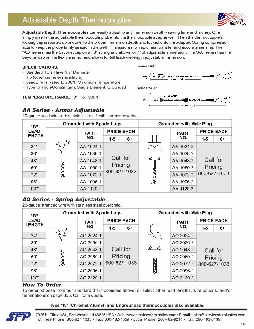
Adjustable Depth ThermocouplesAdjustable Depth Thermocouples can easily adjust to any immersion depth - saving time and money. Onesimply inserts the adjustable thermocouple probe into the thermocouple adapter well. Then the thermocouple’slocking cap is rotated up or down to the proper immersion depth and locked onto the adapter. Spring compressionacts to keep the probe firmly seated in the well. This assures for rapid heat transfer and accurate sensing. The“AO” series has the bayonet cap on an 8” spring and allows for 7” of adjustable immersion. The “AA” series has thebayonet cap on the flexible armor and allows for full leadwire length adjustable immersion.
SPECIFICATIONS:• Standard TC’s Have 3/16” Diameter
Tip (other diameters available)• Leadwire is Rated to 900°F Maximum Temperature• Type “J” (Iron/Constantan), Single Element, Grounded
TEMPERATURE RANGE: 0°F to +900°F
AO Series - Spring Adjustable20-gauge stranded wire with stainless steel overbraid.
"B"LEAD
LENGTH
Grounded with Spade Lugs Grounded with Male Plug
PARTNO.
PRICE EACH PARTNO.
PRICE EACH1-5 6+ 1-5 6+
24" AA-1024-1 AA-1024-236" AA-1036-1 AA-1036-248" AA-1048-1 AA-1048-260" AA-1060-1 AA-1060-272" AA-1072-1 AA-1072-296" AA-1096-1 AA-1096-2120" AA-1120-1 AA-1120-2
"B"LEAD
LENGTH
Grounded with Spade Lugs Grounded with Male Plug
PARTNO.
PRICE EACH PARTNO.
PRICE EACH1-5 6+ 1-5 6+
24" AO-2024-1 AO-2024-236" AO-2036-1 AO-2036-248" AO-2048-1 AO-2048-260" AO-2060-1 AO-2060-272" AO-2072-1 AO-2072-296" AO-2096-1 AO-2096-2120" AO-2120-1 AO-2120-2
AA Series - Armor Adjustable20-gauge solid wire with stainless steel flexible armor covering.
Series “AO”
Series “AA”
How To OrderTo order, choose from our standard thermocouples above; or select other lead lengths, wire options, and/orterminations on page 353. Call for a quote.
Type “K” (Chromel/Alumel) and Ungrounded thermocouples also available.
Call forPricing
800-627-1033
Call forPricing
800-627-1033
Call forPricing
800-627-1033
Call forPricing
800-627-1033
7925 N. Clinton St., Fort Wayne, IN 46825 USA • Web: www.servicesforplastics.com • E-mail: [email protected] Free Phone: 800-627-1033 • Fax: 800-482-4059 • Local Phone: 260-482-9211 • Fax: 260-483-8139
14J
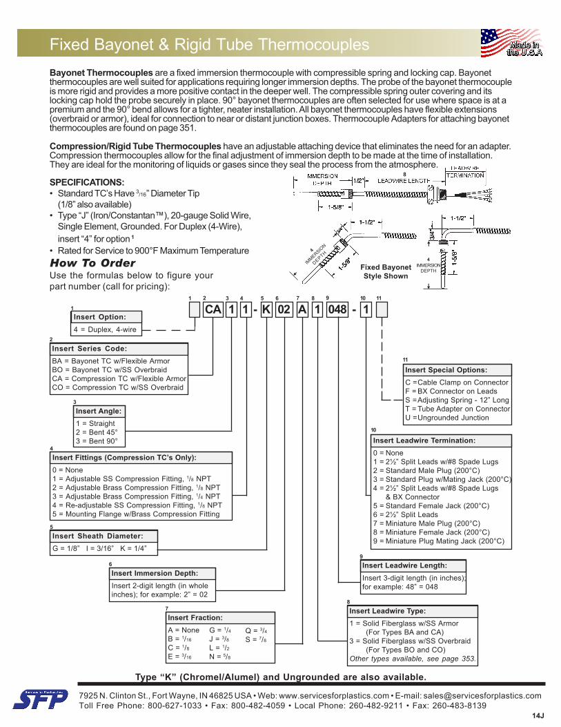
Bayonet Thermocouples are a fixed immersion thermocouple with compressible spring and locking cap. Bayonetthermocouples are well suited for applications requiring longer immersion depths. The probe of the bayonet thermocoupleis more rigid and provides a more positive contact in the deeper well. The compressible spring outer covering and itslocking cap hold the probe securely in place. 90° bayonet thermocouples are often selected for use where space is at apremium and the 90° bend allows for a tighter, neater installation. All bayonet thermocouples have flexible extensions(overbraid or armor), ideal for connection to near or distant junction boxes. Thermocouple Adapters for attaching bayonetthermocouples are found on page 351.
Compression/Rigid Tube Thermocouples have an adjustable attaching device that eliminates the need for an adapter.Compression thermocouples allow for the final adjustment of immersion depth to be made at the time of installation.They are ideal for the monitoring of liquids or gases since they seal the process from the atmosphere.
SPECIFICATIONS:• Standard TC’s Have 3/16” Diameter Tip
(1/8” also available)• Type “J” (Iron/Constantan™), 20-gauge Solid Wire,
Single Element, Grounded. For Duplex (4-Wire),insert “4” for option 1
• Rated for Service to 900°F Maximum Temperature
Fixed Bayonet & Rigid Tube Thermocouples
How To OrderUse the formulas below to figure yourpart number (call for pricing):
Type “K” (Chromel/Alumel) and Ungrounded are also available.
1
Insert Series Code:BA = Bayonet TC w/Flexible ArmorBO = Bayonet TC w/SS OverbraidCA = Compression TC w/Flexible ArmorCO = Compression TC w/SS Overbraid
3
Insert Angle:1 = Straight2 = Bent 45°3 = Bent 90°
9Insert Leadwire Length:Insert 3-digit length (in inches);for example: 48” = 048
6
Insert Immersion Depth:Insert 2-digit length (in wholeinches); for example: 2” = 02
10
Insert Leadwire Termination:0 = None1 = 2½” Split Leads w/#8 Spade Lugs2 = Standard Male Plug (200°C)3 = Standard Plug w/Mating Jack (200°C)4 = 2½” Split Leads w/#8 Spade Lugs
& BX Connector5 = Standard Female Jack (200°C)6 = 2½” Split Leads7 = Miniature Male Plug (200°C)8 = Miniature Female Jack (200°C)9 = Miniature Plug Mating Jack (200°C)
97
CA 1 1 - K 02 A 1 048 - 1 C1 2 4 5 6 8
11
Insert Special Options:C =Cable Clamp on ConnectorF = BX Connector on LeadsS =Adjusting Spring - 12” LongT = Tube Adapter on ConnectorU =Ungrounded Junction
4
Insert Fittings (Compression TC’s Only):0 = None1 = Adjustable SS Compression Fitting, 1/8 NPT2 = Adjustable Brass Compression Fitting, 1/8 NPT3 = Adjustable Brass Compression Fitting, 1/4 NPT4 = Re-adjustable SS Compression Fitting, 1/8 NPT5 = Mounting Flange w/Brass Compression Fitting
8
Insert Leadwire Type:1 = Solid Fiberglass w/SS Armor
(For Types BA and CA)3 = Solid Fiberglass w/SS Overbraid
(For Types BO and CO)Other types available, see page 353.
7
Insert Fraction:A = NoneB = 1/16
C = 1/8
E = 3/16
G = 1/4J = 3/8L = 1/2N = 5/8
Q = 3/4S = 7/8
Insert Option:4 = Duplex, 4-wire
2
3
Fixed BayonetStyle Shown
4IMMERSION
DEPTH
4
IMMERSIO
N
DEPTH
8
5
Insert Sheath Diameter:G = 1/8” I = 3/16” K = 1/4”
10 11
7925 N. Clinton St., Fort Wayne, IN 46825 USA • Web: www.servicesforplastics.com • E-mail: [email protected] Free Phone: 800-627-1033 • Fax: 800-482-4059 • Local Phone: 260-482-9211 • Fax: 260-483-8139
14J
"B"LEAD
LENGTH
Grounded with 2½" Stripped Leads Grounded with Spade Lugs
PARTNO.
PRICE EACH PARTNO.
PRICE EACH1-5 6+ 1-5 6+
24" TN2-3024-6 TN2-3024-1
36" TN2-3036-6 TN2-3036-1
48" TN2-3048-6 TN2-3048-1
60" TN2-3060-6 TN2-3060-1
72" TN2-3072-6 TN2-3072-1
96" TN2-3096-6 TN2-3096-1
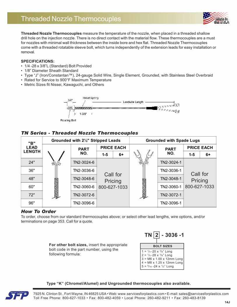
Threaded Nozzle Thermocouples measure the temperature of the nozzle, when placed in a threaded shallowdrill hole on the injection nozzle. There is no direct contact with the material flow. These thermocouples are a mustfor nozzles with minimal wall thickness between the inside bore and hex flat. Threaded Nozzle Thermocouplescome with a threaded rotatable sleeve bolt, which turns independently of the extension leads for easy installation orremoval.
SPECIFICATIONS:• 1/4 -28 x 3/8”L (Standard) Bolt Provided• 1/8” Diameter Sheath Standard• Type “J” (Iron/Constantan™), 24-gauge Solid Wire, Single Element, Grounded, with Stainless Steel Overbraid• Rated for Service to 900°F Maximum Temperature• Metric Sizes fit Nissei, Kawaguchi, and Others
Threaded Nozzle Thermocouples
TN Series - Threaded Nozzle Thermocouples
How To OrderTo order, choose from our standard thermocouples above; or select other lead lengths, wire options, and/orterminations on page 353. Call for a quote.
Type “K” (Chromel/Alumel) and Ungrounded thermocouples also available.
For other bolt sizes, insert the appropriatebolt code in the part number, using thefollowing formula:
TN 2 - 3036 -1
BOLT SIZES1 = 1/4 -20 x 3/8” Long2 = 1/4 -28 x 3/8” Long3 = M6 x 1.00 x 12mm Long4 = M8 x 1.25 x 12mm Long5 = 5/16 -24 x 1/2” Long
Call forPricing
800-627-1033
Call forPricing
800-627-1033
7925 N. Clinton St., Fort Wayne, IN 46825 USA • Web: www.servicesforplastics.com • E-mail: [email protected] Free Phone: 800-627-1033 • Fax: 800-482-4059 • Local Phone: 260-482-9211 • Fax: 260-483-8139
14J
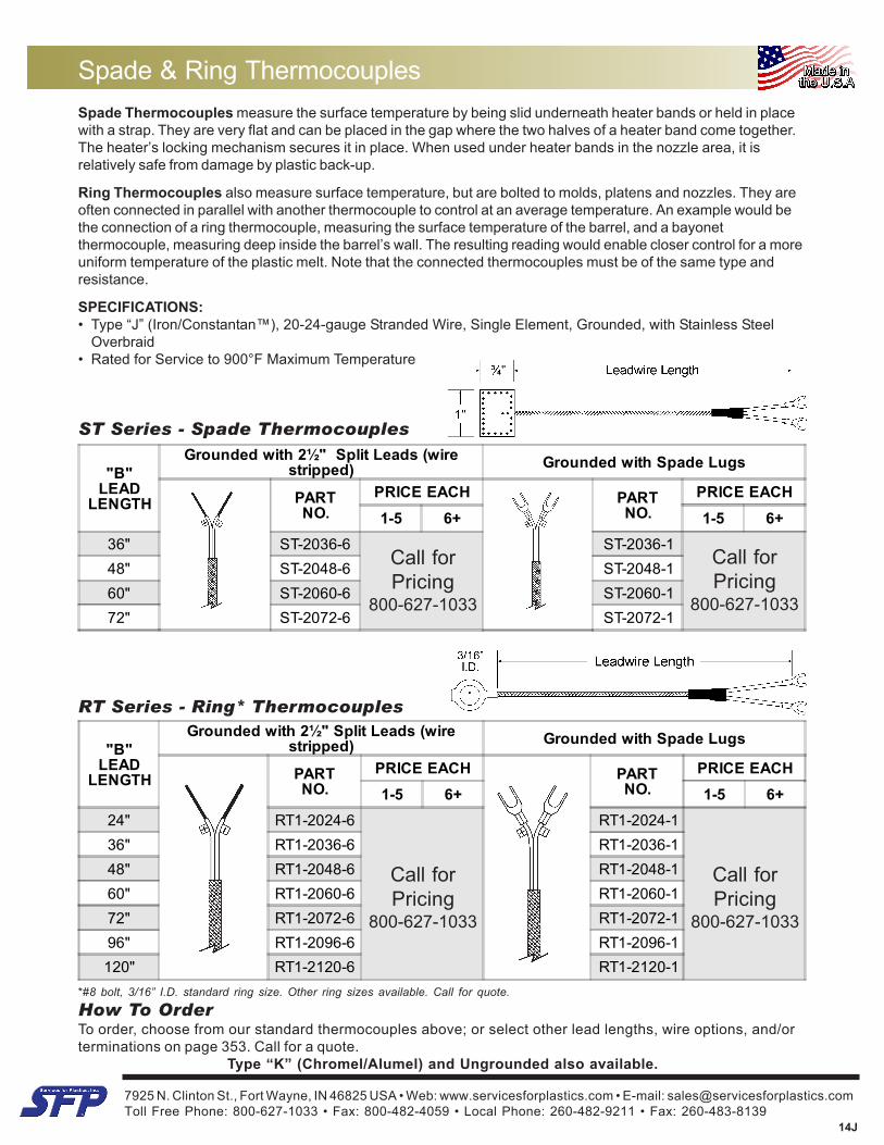
Spade Thermocouples measure the surface temperature by being slid underneath heater bands or held in placewith a strap. They are very flat and can be placed in the gap where the two halves of a heater band come together.The heater’s locking mechanism secures it in place. When used under heater bands in the nozzle area, it isrelatively safe from damage by plastic back-up.
Ring Thermocouples also measure surface temperature, but are bolted to molds, platens and nozzles. They areoften connected in parallel with another thermocouple to control at an average temperature. An example would bethe connection of a ring thermocouple, measuring the surface temperature of the barrel, and a bayonetthermocouple, measuring deep inside the barrel’s wall. The resulting reading would enable closer control for a moreuniform temperature of the plastic melt. Note that the connected thermocouples must be of the same type andresistance.
SPECIFICATIONS:• Type “J” (Iron/Constantan™), 20-24-gauge Stranded Wire, Single Element, Grounded, with Stainless Steel
Overbraid• Rated for Service to 900°F Maximum Temperature
ST Series - Spade Thermocouples
RT Series - Ring* Thermocouples
How To OrderTo order, choose from our standard thermocouples above; or select other lead lengths, wire options, and/orterminations on page 353. Call for a quote.
Type “K” (Chromel/Alumel) and Ungrounded also available.
Spade & Ring Thermocouples
"B"LEAD
LENGTH
Grounded with 2½" Split Leads (wirestripped) Grounded with Spade Lugs
PARTNO.
PRICE EACH PARTNO.
PRICE EACH1-5 6+ 1-5 6+
36" ST-2036-6 ST-2036-148" ST-2048-6 ST-2048-160" ST-2060-6 ST-2060-172" ST-2072-6 ST-2072-1
"B"LEAD
LENGTH
Grounded with 2½" Split Leads (wirestripped) Grounded with Spade Lugs
PARTNO.
PRICE EACH PARTNO.
PRICE EACH1-5 6+ 1-5 6+
24" RT1-2024-6 RT1-2024-136" RT1-2036-6 RT1-2036-148" RT1-2048-6 RT1-2048-160" RT1-2060-6 RT1-2060-172" RT1-2072-6 RT1-2072-196" RT1-2096-6 RT1-2096-1120" RT1-2120-6 RT1-2120-1
*#8 bolt, 3/16” I.D. standard ring size. Other ring sizes available. Call for quote.
Call forPricing
800-627-1033
Call forPricing
800-627-1033
Call forPricing
800-627-1033
Call forPricing
800-627-1033
7925 N. Clinton St., Fort Wayne, IN 46825 USA • Web: www.servicesforplastics.com • E-mail: [email protected] Free Phone: 800-627-1033 • Fax: 800-482-4059 • Local Phone: 260-482-9211 • Fax: 260-483-8139
14J
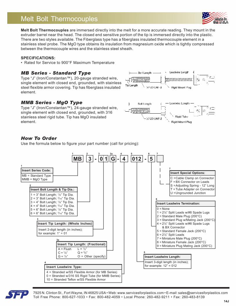
Melt Bolt Thermocouples are immersed directly into the melt for a more accurate reading. They mount in theextruder barrel near the head. The closed end sensitive portion of the tip is immersed directly into the plastic.There are two styles available. The Fiberglass type has a fiberglass insulated thermocouple element in astainless steel probe. The MgO type obtains its insulation from magnesium oxide which is tightly compressedbetween the thermocouple wires and the stainless steel sheath.
SPECIFICATIONS:• Rated for Service to 900°F Maximum Temperature
MB Series - Standard TypeType “J” (Iron/Constantan™), 20-gauge stranded wire,single element with closed end, grounded, with stainlesssteel flexible armor covering. Tip has fiberglass insulatedelement.
MMB Series - MgO TypeType “J” (Iron/Constantan™), 24-gauge stranded wire,single element with closed end, grounded, with 316stainless steel rigid tube. Tip has MgO insulatedelement.
Melt Bolt Thermocouples
MB 3 - 0 1 G - 4 012 - 5 C
How To OrderUse the formula below to figure your part number (call for pricing):
2 3 5
6
Insert Leadwire Termination:0 = None1 = 2½” Split Leads w/#8 Spade Lugs2 = Standard Male Plug (200°C)3 = Standard Plug w/Mating Jack (200°C)4 = 2½” Split Leads w/#8 Spade Lugs
& BX Connector5 = Standard Female Jack (200°C)6 = 2½” Split Leads7 = Miniature Male Plug (200°C)8 = Miniature Female Jack (200°C)9 = Miniature Plug Mating Jack (200°C)
6 7
Insert Special Options:C =Cable Clamp on ConnectorF = BX Connector on LeadsS =Adjusting Spring - 12” LongT = Tube Adapter on ConnectorU =Ungrounded Junction
7
1
1
Insert Series Code:MB = Standard TypeMMB = MgO Type
Insert Bolt Length & Tip Dia.:1 = 3” Bolt Length; 1/8” Tip Dia.2 = 3” Bolt Length; 3/16” Tip Dia.3 = 4” Bolt Length; 1/8” Tip Dia.4 = 4” Bolt Length; 3/16” Tip Dia.5 = 6” Bolt Length; 1/8” Tip Dia.6 = 6” Bolt Length; 3/16” Tip Dia.
2
3
Insert Tip Length: (Whole Inches)
4
4
Insert Leadwire Type:4 = Stranded w/SS Flexible Armor (for MB Series)0 = Stranded w/316 SS Rigid Tube (for MMB Series)10 = Stranded Teflon w/SS Flexible Armor
5
Insert Leadwire Length:Insert 3-digit length (in inches);for example: 12” = 012
3 a
3 a
Insert Tip Length: (Fractional)A = FlushC = 1/8”G = 1/4”
L = 1/2”Q = 3/4”O = Other (specify)
Insert 2-digit length (in inches);for example: 1” = 01
7925 N. Clinton St., Fort Wayne, IN 46825 USA • Web: www.servicesforplastics.com • E-mail: [email protected] Free Phone: 800-627-1033 • Fax: 800-482-4059 • Local Phone: 260-482-9211 • Fax: 260-483-8139
14J
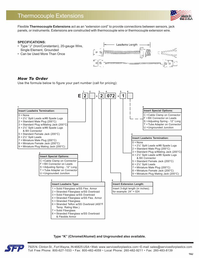
Flexible Thermocouple Extensions act as an “extension cord” to provide connections between sensors, jackpanels, or instruments. Extensions are constructed with thermocouple wire or thermocouple extension wire.
SPECIFICATIONS:• Type “J” (Iron/Constantan), 20-gauge Wire,
Single Element, Grounded• Can be Used More Than Once
E 2 - 2 072 - 1 F
Thermocouple Extensions
How To OrderUse the formula below to figure your part number (call for pricing):
Type “K” (Chromel/Alumel) and Ungrounded also available.
4
Insert Extension Length:Insert 3-digit length (in inches);for example: 24” = 024
3
Insert Leadwire Type:1 = Solid Fiberglass w/SS Flex. Armor2 = Stranded Fiberglass w/SS Overbraid3 = Solid Fiberglass w/SS Overbraid4 = Stranded Fiberglass w/SS Flex. Armor5 = Stranded Fiberglass6 = Stranded Teflon w/SS Overbraid (400°F
Temp. Rating Max.)7 = Solid Fiberglass8 = Stranded Fiberglass w/SS Overbraid
& Flexible Armor
1 2 3 4
1
Insert Leadwire Termination:0 = None1 = 2½” Split Leads w/#8 Spade Lugs2 = Standard Male Plug (200°C)3 = Standard Plug w/Mating Jack (200°C)4 = 2½” Split Leads w/#8 Spade Lugs
& BX Connector5 = Standard Female Jack (200°C)6 = 2½” Split Leads7 = Miniature Male Plug (200°C)8 = Miniature Female Jack (200°C)9 = Miniature Plug Mating Jack (200°C)
5
Insert Leadwire Termination:0 = None1 = 2½” Split Leads w/#8 Spade Lugs2 = Standard Male Plug (200°C)3 = Standard Plug w/Mating Jack (200°C)4 = 2½” Split Leads w/#8 Spade Lugs
& BX Connector5 = Standard Female Jack (200°C)6 = 2½” Split Leads7 = Miniature Male Plug (200°C)8 = Miniature Female Jack (200°C)9 = Miniature Plug Mating Jack (200°C)
5 6
Insert Special Options:C =Cable Clamp on ConnectorF = BX Connector on LeadsS =Adjusting Spring - 12” LongT = Tube Adapter on ConnectorU =Ungrounded Junction
2
Insert Special Options:C =Cable Clamp on ConnectorF = BX Connector on LeadsS =Adjusting Spring - 12” LongT = Tube Adapter on ConnectorU =Ungrounded Junction
6
7925 N. Clinton St., Fort Wayne, IN 46825 USA • Web: www.servicesforplastics.com • E-mail: [email protected] Free Phone: 800-627-1033 • Fax: 800-482-4059 • Local Phone: 260-482-9211 • Fax: 260-483-8139
14J
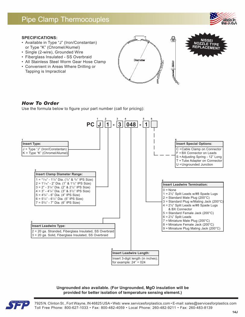
SPECIFICATIONS:• Available in Type “J” (Iron/Constantan)
or Type “K” (Chromel/Alumel)• Single (2-wire), Grounded Wire• Fiberglass Insulated - SS Overbraid• All Stainless Steel Worm Gear Hose Clamp• Convenient in Areas Where Drilling or
Tapping is Impractical
Pipe Clamp Thermocouples
Ungrounded also available. (For Ungrounded, MgO insulation will beprovided for better isolation of temperature sensing element.)
How To OrderUse the formula below to figure your part number (call for pricing):
PC J 1 - 3 048 - 1 F1 2 3 4 5 6
2
Insert Clamp Diameter Range:1 = 11/16” - 11/4” Dia. (1/2” & 3/4” IPS Size)2 = 11/16” - 2” Dia. (1” & 11/2” IPS Size)3 = 2” - 31/4” Dia. (2” & 21/2” IPS Size)4 = 3” - 41/4” Dia. (3” & 31/2” IPS Size)5 = 43/4” - 6” Dia. (4” IPS Size)6 = 51/4” - 61/2” Dia. (5” IPS Size)7 = 53/4” - 7” Dia. (6” IPS Size)
1
Insert Type:J = Type “J” (Iron/Constantan)K = Type “K” (Chromel/Alumel)
4
Insert Leadwire Length:Insert 3-digit length (in inches);for example: 24” = 024
5
Insert Leadwire Termination:0 = None1 = 2½” Split Leads w/#8 Spade Lugs2 = Standard Male Plug (200°C)3 = Standard Plug w/Mating Jack (200°C)4 = 2½” Split Leads w/#8 Spade Lugs
& BX Connector5 = Standard Female Jack (200°C)6 = 2½” Split Leads7 = Miniature Male Plug (200°C)8 = Miniature Female Jack (200°C)9 = Miniature Plug Mating Jack (200°C)
6
Insert Special Options:C =Cable Clamp on ConnectorF = BX Connector on LeadsS =Adjusting Spring - 12” LongT = Tube Adapter on ConnectorU =Ungrounded Junction
NISSEINOZZLE TYPEREPLACEMENT
3
Insert Leadwire Type:2 = 20 ga. Stranded, Fiberglass Insulated, SS Overbraid3 = 20 ga. Solid, Fiberglass Insulated, SS Overbraid
7925 N. Clinton St., Fort Wayne, IN 46825 USA • Web: www.servicesforplastics.com • E-mail: [email protected] Free Phone: 800-627-1033 • Fax: 800-482-4059 • Local Phone: 260-482-9211 • Fax: 260-483-8139
14J
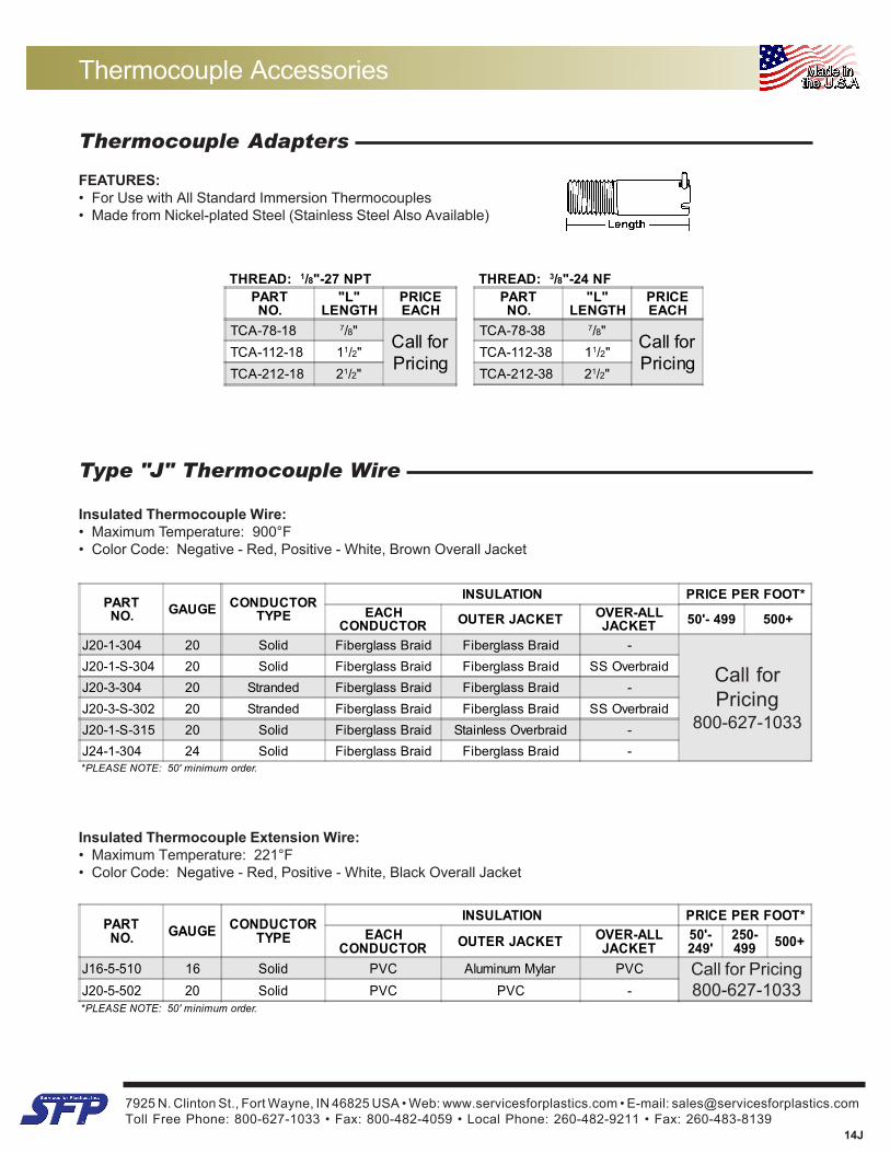
THREAD: 1/8"-27 NPT THREAD: 3/8"-24 NFPARTNO.
"L"LENGTH
PRICEEACH
PARTNO.
"L"LENGTH
PRICEEACH
TCA-78-18 7/8"Call forPricing
TCA-78-38 7/8"Call forPricing
TCA-112-18 11/2" TCA-112-38 11/2"TCA-212-18 21/2" TCA-212-38 21/2"
PARTNO. GAUGE CONDUCTOR
TYPEINSULATION PRICE PER FOOT*
EACHCONDUCTOR OUTER JACKET OVER-ALL
JACKET 50'- 499 500+
J20-1-304 20 Solid Fiberglass Braid Fiberglass Braid -J20-1-S-304 20 Solid Fiberglass Braid Fiberglass Braid SS OverbraidJ20-3-304 20 Stranded Fiberglass Braid Fiberglass Braid -J20-3-S-302 20 Stranded Fiberglass Braid Fiberglass Braid SS OverbraidJ20-1-S-315 20 Solid Fiberglass Braid Stainless Overbraid -J24-1-304 24 Solid Fiberglass Braid Fiberglass Braid -*PLEASE NOTE: 50' minimum order.
Thermocouple Accessories
Thermocouple Adapters
FEATURES:• For Use with All Standard Immersion Thermocouples• Made from Nickel-plated Steel (Stainless Steel Also Available)
Type "J" Thermocouple Wire
Insulated Thermocouple Wire:• Maximum Temperature: 900°F• Color Code: Negative - Red, Positive - White, Brown Overall Jacket
Insulated Thermocouple Extension Wire:• Maximum Temperature: 221°F• Color Code: Negative - Red, Positive - White, Black Overall Jacket
PARTNO. GAUGE CONDUCTOR
TYPEINSULATION PRICE PER FOOT*
EACHCONDUCTOR OUTER JACKET OVER-ALL
JACKET50'-249'
250-499 500+
J16-5-510 16 Solid PVC Aluminum Mylar PVCJ20-5-502 20 Solid PVC PVC -*PLEASE NOTE: 50' minimum order.
Call forPricing
800-627-1033
Call for Pricing800-627-1033
7925 N. Clinton St., Fort Wayne, IN 46825 USA • Web: www.servicesforplastics.com • E-mail: [email protected] Free Phone: 800-627-1033 • Fax: 800-482-4059 • Local Phone: 260-482-9211 • Fax: 260-483-8139
14J
Thermocouple Accessories
PART NO. DESCRIPTION PRICE EACH1-11 12+
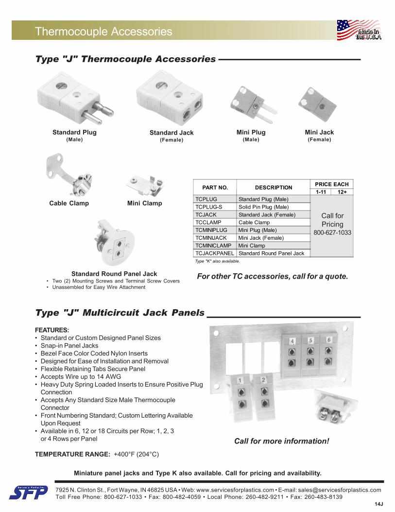
TCPLUG Standard Plug (Male)TCPLUG-S Solid Pin Plug (Male)TCJACK Standard Jack (Female)TCCLAMP Cable ClampTCMINIPLUG Mini Plug (Male)TCMINIJACK Mini Jack (Female)TCMINICLAMP Mini ClampTCJACKPANEL Standard Round Panel JackType "K" also available.
Type "J" Thermocouple Accessories
For other TC accessories, call for a quote.
Standard Plug(Male)
Standard Jack(Female)
Cable Clamp
Mini Plug(Male)
Mini Jack(Female)
Mini Clamp
Type "J" Multicircuit Jack Panels
FEATURES:• Standard or Custom Designed Panel Sizes• Snap-in Panel Jacks• Bezel Face Color Coded Nylon Inserts• Designed for Ease of Installation and Removal• Flexible Retaining Tabs Secure Panel• Accepts Wire up to 14 AWG• Heavy Duty Spring Loaded Inserts to Ensure Positive Plug
Connection• Accepts Any Standard Size Male Thermocouple
Connector• Front Numbering Standard; Custom Lettering Available
Upon Request• Available in 6, 12 or 18 Circuits per Row; 1, 2, 3
or 4 Rows per Panel
TEMPERATURE RANGE: +400°F (204°C)
Miniature panel jacks and Type K also available. Call for pricing and availability.
Call for more information!
Standard Round Panel Jack• Two (2) Mounting Screws and Terminal Screw Covers• Unassembled for Easy Wire Attachment
Call forPricing
800-627-1033
7925 N. Clinton St., Fort Wayne, IN 46825 USA • Web: www.servicesforplastics.com • E-mail: [email protected] Free Phone: 800-627-1033 • Fax: 800-482-4059 • Local Phone: 260-482-9211 • Fax: 260-483-8139
14J
TC/RTD Wire & Termination Options
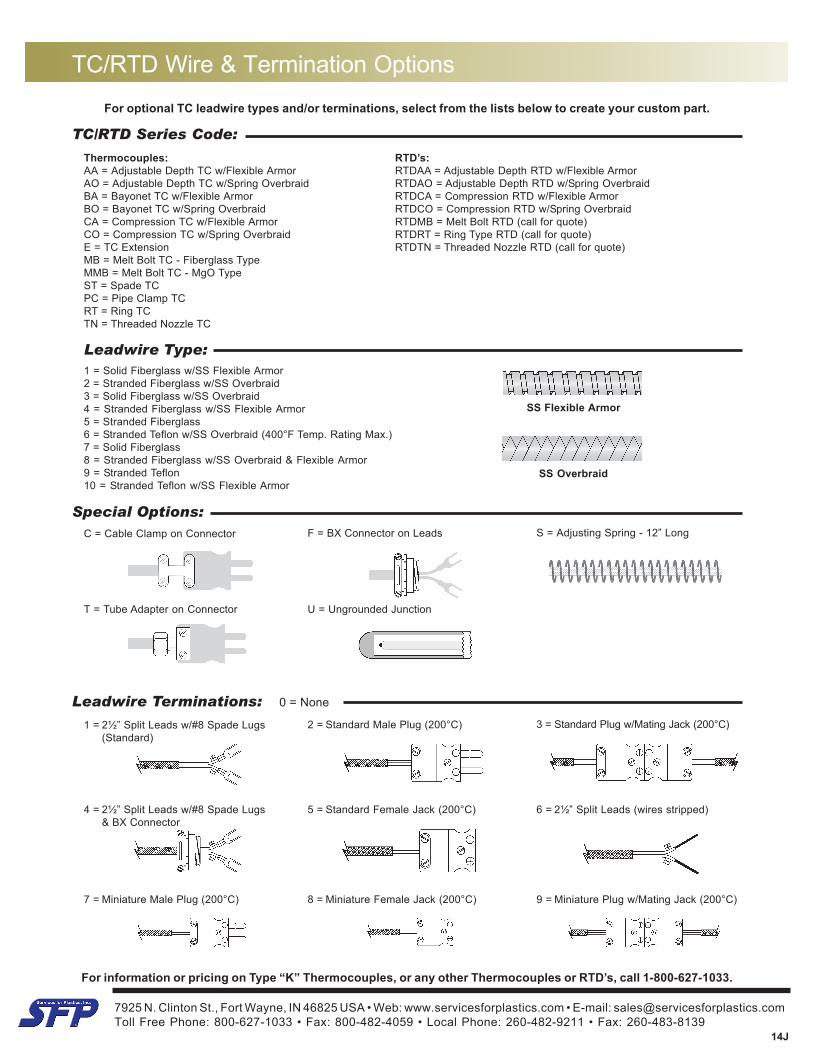
For optional TC leadwire types and/or terminations, select from the lists below to create your custom part.
TC/RTD Series Code:
Leadwire Terminations: 0 = None
1 = 2½” Split Leads w/#8 Spade Lugs(Standard)
2 = Standard Male Plug (200°C) 3 = Standard Plug w/Mating Jack (200°C)
4 = 2½” Split Leads w/#8 Spade Lugs& BX Connector
5 = Standard Female Jack (200°C) 6 = 2½” Split Leads (wires stripped)
7 = Miniature Male Plug (200°C) 8 = Miniature Female Jack (200°C)
For information or pricing on Type “K” Thermocouples, or any other Thermocouples or RTD’s, call 1-800-627-1033.
Leadwire Type:1 = Solid Fiberglass w/SS Flexible Armor2 = Stranded Fiberglass w/SS Overbraid3 = Solid Fiberglass w/SS Overbraid4 = Stranded Fiberglass w/SS Flexible Armor5 = Stranded Fiberglass6 = Stranded Teflon w/SS Overbraid (400°F Temp. Rating Max.)7 = Solid Fiberglass8 = Stranded Fiberglass w/SS Overbraid & Flexible Armor9 = Stranded Teflon10 = Stranded Teflon w/SS Flexible Armor
9 = Miniature Plug w/Mating Jack (200°C)
Special Options:C = Cable Clamp on Connector F = BX Connector on Leads S = Adjusting Spring - 12” Long
T = Tube Adapter on Connector U = Ungrounded Junction
Thermocouples:AA = Adjustable Depth TC w/Flexible ArmorAO = Adjustable Depth TC w/Spring OverbraidBA = Bayonet TC w/Flexible ArmorBO = Bayonet TC w/Spring OverbraidCA = Compression TC w/Flexible ArmorCO = Compression TC w/Spring OverbraidE = TC ExtensionMB = Melt Bolt TC - Fiberglass TypeMMB = Melt Bolt TC - MgO TypeST = Spade TCPC = Pipe Clamp TCRT = Ring TCTN = Threaded Nozzle TC
RTD’s:RTDAA = Adjustable Depth RTD w/Flexible ArmorRTDAO = Adjustable Depth RTD w/Spring OverbraidRTDCA = Compression RTD w/Flexible ArmorRTDCO = Compression RTD w/Spring OverbraidRTDMB = Melt Bolt RTD (call for quote)RTDRT = Ring Type RTD (call for quote)RTDTN = Threaded Nozzle RTD (call for quote)
SS Flexible Armor
SS Overbraid
7925 N. Clinton St., Fort Wayne, IN 46825 USA • Web: www.servicesforplastics.com • E-mail: [email protected] Free Phone: 800-627-1033 • Fax: 800-482-4059 • Local Phone: 260-482-9211 • Fax: 260-483-8139
14J
Adjustable Depth RTD’s
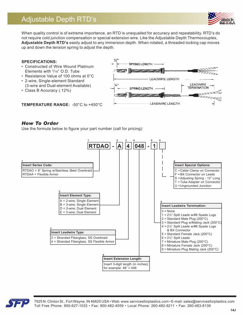
When quality control is of extreme importance, an RTD is unequalled for accuracy and repeatability. RTD’s donot require cold junction compensation or special extension wire. Like the Adjustable Depth Thermocouples,Adjustable Depth RTD’s easily adjust to any immersion depth. When rotated, a threaded locking cap movesup and down the tension spring to adjust the depth.
SPECIFICATIONS:• Constructed of Wire Wound Platinum
Elements with 3/16” O.D. Tube• Resistance Value of 100 ohms at 0°C• 2-wire, Single-element Standard
(3-wire and Dual-element Available)• Class B Accuracy (.12%)
TEMPERATURE RANGE: -50°C to +450°C
How To OrderUse the formula below to figure your part number (call for pricing):
5
Insert Leadwire Termination:0 = None1 = 2½” Split Leads w/#8 Spade Lugs2 = Standard Male Plug (200°C)3 = Standard Plug w/Mating Jack (200°C)4 = 2½” Split Leads w/#8 Spade Lugs
& BX Connector5 = Standard Female Jack (200°C)6 = 2½” Split Leads7 = Miniature Male Plug (200°C)8 = Miniature Female Jack (200°C)9 = Miniature Plug Mating Jack (200°C)
6
Insert Special Options:C =Cable Clamp on ConnectorF = BX Connector on LeadsS =Adjusting Spring - 12” LongT = Tube Adapter on ConnectorU =Ungrounded Junction
1
Insert Series Code:RTDAO = 8” Spring w/Stainless Steel OverbraidRTDAA = Flexible Armor
2
Insert Element Type:A = 2-wire; Single ElementB = 3-wire; Single ElementD = 2-wire; Dual ElementE = 3-wire; Dual Element
4Insert Extension Length:Insert 3-digit length (in inches);for example: 48” = 048
RTDAO - A 4 048 - 1 F1 2 3 4 5 6
3Insert Leadwire Type:2 = Stranded Fiberglass, SS Overbraid4 = Stranded Fiberglass, SS Flexible Armor
7925 N. Clinton St., Fort Wayne, IN 46825 USA • Web: www.servicesforplastics.com • E-mail: [email protected] Free Phone: 800-627-1033 • Fax: 800-482-4059 • Local Phone: 260-482-9211 • Fax: 260-483-8139
14J
Fixed Bayonet & Rigid Tube RTD’s
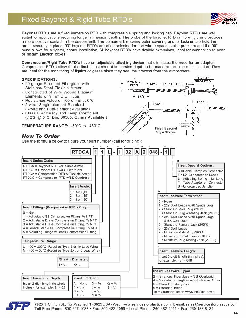
Bayonet RTD’s are a fixed immersion RTD with compressible spring and locking cap. Bayonet RTD’s are wellsuited for applications requiring longer immersion depths. The probe of the bayonet RTD is more rigid and providesa more positive contact in the deeper well. The compressible spring outer covering and its locking cap hold theprobe securely in place. 90° bayonet RTD’s are often selected for use where space is at a premium and the 90°bend allows for a tighter, neater installation. All bayonet RTD’s have flexible extensions, ideal for connection to nearor distant junction boxes.
Compression/Rigid Tube RTD’s have an adjustable attaching device that eliminates the need for an adapter.Compression RTD’s allow for the final adjustment of immersion depth to be made at the time of installation. Theyare ideal for the monitoring of liquids or gases since they seal the process from the atmosphere.
SPECIFICATIONS:• 20-gauge Stranded Fiberglass with
Stainless Steel Flexible Armor• Constructed of Wire Wound Platinum
Elements with 3/16” O.D. Tube• Resistance Value of 100 ohms at 0°C• 2-wire, Single-element Standard
(3-wire and Dual-element Available)• Class B Accuracy and Temp Coefficient
(.12% @ 0°C, Din. 00385. Others Available.)
TEMPERATURE RANGE: -50°C to +450°C
How To OrderUse the formula below to figure your part number (call for pricing):
2Insert Angle:1 = Straight2 = Bent 45°3 = Bent 90°
9
Insert Leadwire Length:Insert 3-digit length (in inches);for example: 48” = 048
6Insert Immersion Depth:Insert 2-digit length (in wholeinches); for example: 2” = 02
10
Insert Leadwire Termination:0 = None1 = 2½” Split Leads w/#8 Spade Lugs2 = Standard Male Plug (200°C)3 = Standard Plug w/Mating Jack (200°C)4 = 2½” Split Leads w/#8 Spade Lugs
& BX Connector5 = Standard Female Jack (200°C)6 = 2½” Split Leads7 = Miniature Male Plug (200°C)8 = Miniature Female Jack (200°C)9 = Miniature Plug Mating Jack (200°C)
119
RTDCA 1 1 L - I 02 A 2 048 - 1 C1 2 3 4 7 8 10
7
Insert Fraction:A = NoneB = 1/16
C = 1/8E = 3/16
G = 1/4J = 3/8L = 1/2N = 5/8
Q = 3/4S = 7/8
11
Insert Special Options:C =Cable Clamp on ConnectorF = BX Connector on LeadsS =Adjusting Spring - 12” LongT = Tube Adapter on ConnectorU =Ungrounded Junction
3
Insert Fittings (Compression RTD’s Only):0 = None1 = Adjustable SS Compression Fitting, 1/8 NPT2 = Adjustable Brass Compression Fitting, 1/8 NPT3 = Adjustable Brass Compression Fitting, 1/4 NPT4 = Re-adjustable SS Compression Fitting, 1/8 NPT5 = Mounting Flange w/Brass Compression Fitting
1Insert Series Code:RTDBA = Bayonet RTD w/Flexible ArmorRTDBO = Bayonet RTD w/SS OverbraidRTDCA = Compression RTD w/Flexible ArmorRTDCO = Compression RTD w/SS Overbraid
8Insert Leadwire Type:2 = Stranded Fiberglass w/SS Overbraid4 = Stranded Fiberglass w/SS Flexible Armor5 = Stranded Fiberglass9 = Stranded Teflon10 = Stranded Teflon w/SS Flexible Armor
Fixed BayonetStyle Shown
4
4
IMMERSIO
N
DEPTH4
IMMERSIONDEPTH
4Temperature Range:L = -50 + 200°C (Requires Type 9 or 10 Lead Wire)M = -50 +450°C (Requires Type 2,4, or 5 Lead Wire)
5
Sheath Diameter:I = 3/16 K= 1/4
65