Thermo Scientific Forma 8600 Series 8600 Series Thermo Scientific Preface Do You Need Information or...
116
Visit us online to register your warranty www.thermoscientific.com/labwarranty User Manual Thermo Scientific Forma 8600 Series -40C and -86C ULT Chest Freezer Operating and Maintenance Manual 7028700 Rev. 5
Transcript of Thermo Scientific Forma 8600 Series 8600 Series Thermo Scientific Preface Do You Need Information or...

Visit us online to register your warrantywww.thermoscientific.com/labwarranty
User M
anual
Thermo Scientific Forma 8600 Series-40C and -86C ULT Chest FreezerOperating and Maintenance Manual 7028700 Rev. 5

Thermo Scientific
MANUAL NUMBER 7028700
5 40497/FR-2843 5/12/16 Updated refrigeration and electrical schematics - Schurter switch ccs
4 40544 12/9/15 BUS information (preventive maintenance and BUS control panel and operation) ccs
3 40286/FR-2805 6/30/15 New start relay - expl enclosure drawing and 8702 & 8722 elec schematics ccs
2 31013/FR-2673 6/18/14 RoHS compliant washer on oil separator (expl base dwg, refrig schematics) ccs
1 30775/30673/FR-2607 2/4/14 Intended use and battery check - pgs ii & 5-4 ccs
-- 30369/FR-2548 9/25/13 Pressure change on refrigeration schematics ccs
Preface
8600 Series i
-86C Models Covered
Number Model Cu. ft. Voltage/Hz
803CA 8700 3 120/60
803CV 8701 3 230/50
813CV 8702 12.7 230/50
813CD 8703 12.7 230/60
813CA 8704 12.7 120/60
817CA 8705 17 120/60
817CV 8706 17 230/50
817CD 8707 17 230/60
820CV 8708 20 230/50
820CD 8709 20 230/60
820CA 8710 20 120/60
Part No. Description Qty
213F Key 2
380520 Neoprene Cap 2
510016 1/4-20 x 5-1/2” Bolt 2
195763 Retaining Clip 1
370563 Remote Alarm Connector 1
Packing List
-40C Models Covered
Number Model Cu. ft. Voltage/Hz
703CA 8718 3 120/60
703CV 8719 3 230/50
713CV 8722 12.7 230/50
713CD 8727 12.7 230/60
713CA 8728 12.7 120/60
717CA 8730 17 120/60
717CV 8731 17 230/50
717CD 8733 17 230/60
720CV 8734 20 230/50
720CD 8736 20 230/60
720CA 8737 20 120/60
Important installer and user information:A redundant temperature sensing device has been included in this ULT freezer. Thisdevice is a type “T” thermocouple. For convenient access, the thermocouple (Figure 1-3) terminates in an interconnect jack (Figure 1-5) behind the base front cover. (May belocated differently in chests. See Section 1.) It is strongly recommended that this ther-mocouple be attached to a redundant 24 hour 7 day monitoring system with alarmcapabilities. Connecting the sensor to a monitoring and alarm system separate from thefreezer provides the utmost in product safety, should the integral system fail. s

Thermo Scientificii 8600 Series
Preface
Contains Parts and Assemblies
Susceptible to Damage by
Electrostatic Discharge (ESD)
CAUTION
Important Read this operating manual. Failure to read, understand and follow the instructions in this manualmay result in damage to the unit, injury to operating personnel, and poor equipment performance. s
Caution All internal adjustments and maintenance must be performed by qualified service personnel. s
Material in this manual is for information purposes only. The contents and the product it describes are subjectto change without notice. Thermo Fisher Scientific makes no representations or warranties with respect to thismanual. In no event shall Thermo be held liable for any damages, direct or incidental, arising out of or relatedto the use of this manual.
The -40C and -86C freezers (see page i for model numbers) described in this manual are high performanceunits which can be used for research and in situations that directly support medical applications. When theseproducts are used to support a medical application, it is an accessory to a medical device and is thereforconsidered as a medical device in its own right by the regulatory body ( e.g. FDA).
This product is intended for use:• as cold storage in research use• as a medical device for diagnostic use (storage of samples not intended to be re-introduced to the humanbody).
Registration: This medical application is considered a Class I device by the FDA. This product is classified asproduct code - JRM, regulation number 862.2050 and is considered a Class I device, 510(K) exempt.
© 2013 Thermo Fisher Scientific. All rights reserved.

8600 Series iiiThermo Scientific
Preface
Important operating and/or maintenance instructions. Read the accompanying text carefully.
Potential electrical hazards. Only qualified persons should perform procedures associated with thissymbol.
Equipment being maintained or serviced must be turned off and locked off to prevent possible injury.
Extreme temperature hazards, hot or cold. Use special handling equipment or wear special, protectiveclothing.
WEEE Compliance: Thermo Fisher Scientific has contracted with companies for recycling/disposal ineach EU Member State. For further information, send an email to [email protected].
4 Always use the proper protective equipment (clothing, gloves, goggles, etc.)
4 Always dissipate extreme cold or heat and wear protective clothing.
4 Always follow good hygiene practices.
4 Each individual is responsible for his or her own safety.

Thermo Scientificiv 8600 Series
Preface
Do You Need Information or Assistance on
Thermo Scientific Products?
If you do, please contact us 8:00 a.m. to 6:00 p.m. (Eastern Time) at:
1-740-373-4763 Direct
1-800-438-4851 Toll Free, U.S. and Canada
1-877-213-8051 FAX
http://www.thermoscientific.com Internet Worldwide Web Home Page
[email protected] Tech Support Email Address
Certified Service Web Pagewww.unitylabservices.com
Our staff can provide information on pricing and give you quotations. We canSales Support
take your order and provide delivery information on major equipment items or make
arrangements to have your local sales representative contact you. Our products are listed on the
Internet and we can be contacted through our Internet home page.
Our staff can supply technical information about proper setup, operation orService Support
troubleshooting of your equipment. We can fill your needs for spare or replacement parts or
provide you with on-site service. We can also provide you with a quotation on our Extended
Warranty for your Thermo Scientific products.
Whatever Thermo Scientific products you need or use, we will be happy to discuss your
applications. If you are experiencing technical problems, working together, we will help you
locate the problem and, chances are, correct it yourself...over the telephone without a service
call.
When more extensive service is necessary, we will assist you with direct factory trained
technicians or a qualified service organization for on-the-spot repair. If your service need is
covered by the warranty, we will arrange for the unit to be repaired at our expense and to your
satisfaction.
Regardless of your needs, our professional telephone technicians are available to assist you
Monday through Friday from 8:00 a.m. to 6:00 p.m. Eastern Time. Please contact us by
telephone or fax. If you wish to write, our mailing address is:
Thermo Fisher Scientific (Asheville) LLC
401 Millcreek Road, Box 649
Marietta, OH 45750
International customers, please contact your local Thermo Scientific distributor.

8600 Series vThermo Scientific
Table of Contents
Installation and Start-up . . . . . . . . . . . . . . . . . . . . . . . . . . . . . . . . . . . . . .1-1Control Panel Keys, Display, Indicators . . . . . . . . . . . . . . . . . . . . . . .1-5Install Freezer . . . . . . . . . . . . . . . . . . . . . . . . . . . . . . . . . . . . . . . . . . .1-7
Displays . . . . . . . . . . . . . . . . . . . . . . . . . . . . . . . . . . . . . . . . . . . . .1-7RS-232 Communications . . . . . . . . . . . . . . . . . . . . . . . . . . . . . . . .1-8Install Wall Bumpers . . . . . . . . . . . . . . . . . . . . . . . . . . . . . . . . . . . .1-8Choose Location . . . . . . . . . . . . . . . . . . . . . . . . . . . . . . . . . . . . . . .1-8Remote Alarm Contacts and Analog Output . . . . . . . . . . . . . . . . .1-9Connect Unit to Electrical Power . . . . . . . . . . . . . . . . . . . . . . . . .1-10Attach Power Cord . . . . . . . . . . . . . . . . . . . . . . . . . . . . . . . . . . . .1-10
Freezer Start-Up . . . . . . . . . . . . . . . . . . . . . . . . . . . . . . . . . . . . . . . .1-11Set Operating Temperature . . . . . . . . . . . . . . . . . . . . . . . . . . . . . .1-11Set Low Temperature Alarm . . . . . . . . . . . . . . . . . . . . . . . . . . . . .1-12Set High Temperature Alarm . . . . . . . . . . . . . . . . . . . . . . . . . . . .1-12Access Code . . . . . . . . . . . . . . . . . . . . . . . . . . . . . . . . . . . . . . . . .1-13
Run Mode . . . . . . . . . . . . . . . . . . . . . . . . . . . . . . . . . . . . . . . . . . . .1-13
Calibrate . . . . . . . . . . . . . . . . . . . . . . . . . . . . . . . . . . . . . . . . . . . . . . . . . . . .2-1Calibrate Mode . . . . . . . . . . . . . . . . . . . . . . . . . . . . . . . . . . . . . . . . .2-1
Calibrate Control Probe . . . . . . . . . . . . . . . . . . . . . . . . . . . . . . . . .2-1
Configuration . . . . . . . . . . . . . . . . . . . . . . . . . . . . . . . . . . . . . . . . . . . . . . . .3-1Low Alarm Test . . . . . . . . . . . . . . . . . . . . . . . . . . . . . . . . . . . . . . .3-1High Alarm Test . . . . . . . . . . . . . . . . . . . . . . . . . . . . . . . . . . . . . . .3-1BUS Battery Test . . . . . . . . . . . . . . . . . . . . . . . . . . . . . . . . . . . . . .3-2System Battery Test . . . . . . . . . . . . . . . . . . . . . . . . . . . . . . . . . . . .3-2Set Access Code . . . . . . . . . . . . . . . . . . . . . . . . . . . . . . . . . . . . . . .3-3Clear High Stage Alarm . . . . . . . . . . . . . . . . . . . . . . . . . . . . . . . . .3-3Display Temperature . . . . . . . . . . . . . . . . . . . . . . . . . . . . . . . . . . . .3-3Back Up System Type . . . . . . . . . . . . . . . . . . . . . . . . . . . . . . . . . . .3-4RS485 Address . . . . . . . . . . . . . . . . . . . . . . . . . . . . . . . . . . . . . . . .3-4
Reset Excursion . . . . . . . . . . . . . . . . . . . . . . . . . . . . . . . . . . . . . . . . .3-4Warm Excursion . . . . . . . . . . . . . . . . . . . . . . . . . . . . . . . . . . . . . . . .3-4Cold Excursion . . . . . . . . . . . . . . . . . . . . . . . . . . . . . . . . . . . . . . . . .3-4
Section 1
Section 2
Section 3

vi 8600 Series Thermo Scientific
Alarms . . . . . . . . . . . . . . . . . . . . . . . . . . . . . . . . . . . . . . . . . . . . . . . . . . . . . .4-1Lost Communication . . . . . . . . . . . . . . . . . . . . . . . . . . . . . . . . . . .4-2Micro Board Failure Alarm . . . . . . . . . . . . . . . . . . . . . . . . . . . . . . .4-2Multiple Alarms . . . . . . . . . . . . . . . . . . . . . . . . . . . . . . . . . . . . . . .4-2High Stage System Failure Alarm . . . . . . . . . . . . . . . . . . . . . . . . . .4-2
Maintenance . . . . . . . . . . . . . . . . . . . . . . . . . . . . . . . . . . . . . . . . . . . . . . . .5-1Clean Condenser . . . . . . . . . . . . . . . . . . . . . . . . . . . . . . . . . . . . . . . .5-1Clean Air Filter . . . . . . . . . . . . . . . . . . . . . . . . . . . . . . . . . . . . . . . . .5-1Defrost Chamber . . . . . . . . . . . . . . . . . . . . . . . . . . . . . . . . . . . . . . . .5-2Clean Lid Gasket . . . . . . . . . . . . . . . . . . . . . . . . . . . . . . . . . . . . . . . .5-2Replace Battery(s) . . . . . . . . . . . . . . . . . . . . . . . . . . . . . . . . . . . . . . .5-2Check Battery(s) . . . . . . . . . . . . . . . . . . . . . . . . . . . . . . . . . . . . . . . .5-4Prepare Unit for Storage . . . . . . . . . . . . . . . . . . . . . . . . . . . . . . . . . .5-5
PREVENTIVE MAINTENANCE . . . . . . . . . . . . . . . . . . . . . . . . .5-6
Factory Installed Options . . . . . . . . . . . . . . . . . . . . . . . . . . . . . . . . . . . . . .6-1Back Up System (BUS) . . . . . . . . . . . . . . . . . . . . . . . . . . . . . . . . . . .6-1
Install Injection Assembly . . . . . . . . . . . . . . . . . . . . . . . . . . . . . . . .6-1Install Temperature Probe . . . . . . . . . . . . . . . . . . . . . . . . . . . . . . . .6-2BUS Control Panel . . . . . . . . . . . . . . . . . . . . . . . . . . . . . . . . . . . .6-4Connect Probe/Solenoid Harness . . . . . . . . . . . . . . . . . . . . . . . . . .6-4Set Optional BUS Set Point . . . . . . . . . . . . . . . . . . . . . . . . . . . . . .6-5Configure Optional Back Up System (BUS) . . . . . . . . . . . . . . . . . .6-5Test the BUS . . . . . . . . . . . . . . . . . . . . . . . . . . . . . . . . . . . . . . . . .6-6Disconnect Fitting Assembly, Transfer Hose . . . . . . . . . . . . . . . . .6-6
Chart Recorder . . . . . . . . . . . . . . . . . . . . . . . . . . . . . . . . . . . . . . . . .6-6Calibrate Chart Recorder . . . . . . . . . . . . . . . . . . . . . . . . . . . . . . . .6-7Change Program . . . . . . . . . . . . . . . . . . . . . . . . . . . . . . . . . . . . . . .6-7Install Chart Paper . . . . . . . . . . . . . . . . . . . . . . . . . . . . . . . . . . . . .6-7
Specifications . . . . . . . . . . . . . . . . . . . . . . . . . . . . . . . . . . . . . . . . . . . . . . .7-1
Exploded Parts Drawings . . . . . . . . . . . . . . . . . . . . . . . . . . . . . . . . . . . . .8-1
Refrigeration Schematics . . . . . . . . . . . . . . . . . . . . . . . . . . . . . . . . . . . . .9-1
Electrical Schematics . . . . . . . . . . . . . . . . . . . . . . . . . . . . . . . . . . . . . . .10-1
Warranty Information . . . . . . . . . . . . . . . . . . . . . . . . . . . . . . . . . . . . . . . .11-1
Handling Liquid Nitrogen . . . . . . . . . . . . . . . . . . . . . . . . . . . . . . . . . . . . .A -1Handling Liquid CO2 . . . . . . . . . . . . . . . . . . . . . . . . . . . . . . . . . . .A -4First Aid . . . . . . . . . . . . . . . . . . . . . . . . . . . . . . . . . . . . . . . . . . . . .C - 1
Table of Contents
Section 4
Section 5
Section 6
Section 7
Section 8
Appendix
Section 9
Section 10
Section 11

8600 Series 1-1Thermo Scientific
Section 1 Installation and Start-up
Figures 1-1 and 1-2 show the front view of the freezer and indicate thefollowing freezer components:
• Control Panel - keypad, displays and indicators.
• BUS (Optional Back Up System) panel.
• Optional temperature recorder (7 day, one pen) or datalogger.
• Keylock - keyed lid lock.
Optional Back Up
System Controls
Control Panel
Optional
Datalogger
or Recorder
Key lock
Figure 1-1. Front View 3 cu ft Models
EnviroScanControl
OptionalBUS Control
Keylock
Optional Recorderor Datalogger
Figure 1-2. Front View Remaining Models

1-2 8600 Series Thermo Scientific
Section 1Installation and Start-up
Figures 1-3 and 1-4 display the rear view of the freezer and indicate thefollowing freezer components:
• Remote alarm contacts and selectable analog output connection: 0-1V, 4-20mA (default), 0-5V.
• Power inlet for power cord connection.
• Optional BUS connections for probe and solenoid.
• RS-232 or RS-485 interface.
• Power Switch (mains disconnect).
Optional BUS battery
(just behind this panel)
Optional
BUS Connections
RS-232 or RS-485
Interface
Remote Alarm Contacts
and Analog Output
Power Switch
(mains disconnect)
Power Inlet
Threaded holes for
wall bumpers
Access Port
Figure 1-3. Rear View 3 cu ft Models
Threaded holes for
wall bumpers
Remote Alarm Contacts
and Analog Output
Optional
BUS Connections
Power Inlet
Power Switch
(mains disconnect)
RS-232 or RS-485
Interface
Figure 1-4. Rear View Remaining Models
Access Port

8600 Series 1-3Thermo Scientific
Section 1Installation and Start-up
The probe cover houses the control, optional recorder, datalogger, 1535alarm, or BUS probes.
Figures 1-6, 1-7, and 1-8 indicate the following components:
• Freezer filter location
• Battery power switch (freezer and BUS)
• Thermocouple receptacle
• Battery mounting bracket
• Freezer and optional BUS battery
Figure 1-5. Probe Cover
aaaaaaaaaaaaaaaaaaaaaaaaaaaaaaaaaaaaaaaaaaaaaaaaaaaaaaaaaaaaaaaaaaaaaaaaaaaaaaaaaaaaaaaaaaaaaaaaaaaaaaaaaaaaaaaaaaaaaaaaaaaaaaTo remove
filter
Thermocouple
interconnect jack
O
Battery
Switch
Condenser
Figure 1-6. All Models Except 3 cu ft

1-4 8600 Series Thermo Scientific
Section 1Installation and Start-up
microboard
battery
bracket
batteryswitch
probeaccessport
Figure 1-7. Freezer Left Side - Sidecar panel removed
O
aaaaaaaaaaaaaaaaaaaaaaaaaaaaaaaaaaaaaaaaaaaaaaaaaaaaaaaaaaaaaaaaaaaaaaaaaaaaaaaaaaaaaaaaaaaaaaaaaaaaaaaaaaaaaaaaaaaaaaaaO
System
battery
Battery
switch
Thermocouple
interconnect jack
To
remove filter
Figure 1-8. 3 cu ft Models
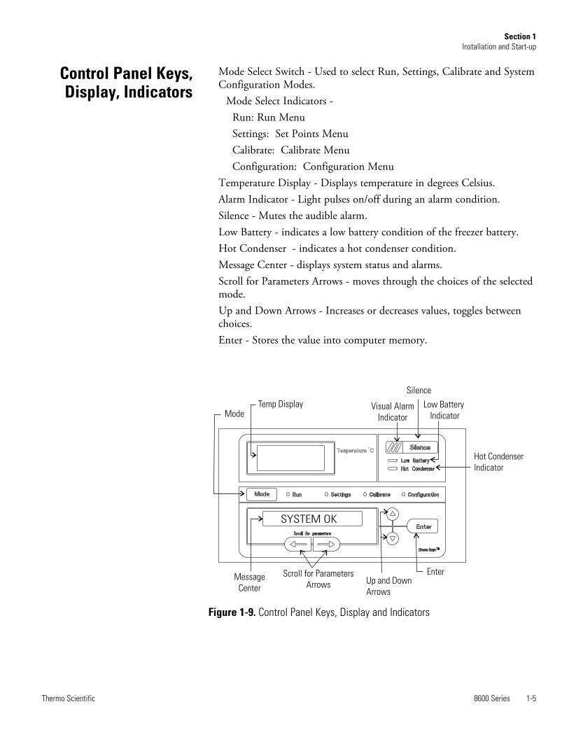
Mode Select Switch - Used to select Run, Settings, Calibrate and SystemConfiguration Modes. Mode Select Indicators - Run: Run Menu Settings: Set Points Menu Calibrate: Calibrate Menu Configuration: Configuration MenuTemperature Display - Displays temperature in degrees Celsius.Alarm Indicator - Light pulses on/off during an alarm condition. Silence - Mutes the audible alarm. Low Battery - indicates a low battery condition of the freezer battery.Hot Condenser - indicates a hot condenser condition.Message Center - displays system status and alarms. Scroll for Parameters Arrows - moves through the choices of the selectedmode.Up and Down Arrows - Increases or decreases values, toggles betweenchoices. Enter - Stores the value into computer memory.
8600 Series 1-5Thermo Scientific
Section 1Installation and Start-up
SYSTEM OK
ModeTemp Display Visual Alarm
Indicator
Silence
Low Battery
Indicator
Hot Condenser
Indicator
Message
Center
Scroll for Parameters
Arrows Up and Down
Arrows
Enter
Figure 1-9. Control Panel Keys, Display and Indicators
Control Panel Keys,Display, Indicators

8600 Series freezers have four basic modes which allow freezer setup: Run,Settings, Calibrate and Configuration.
Run is the default mode which the freezer will normally be in duringoperation.
Settings is used to enter system set points for freezer operation.
Calibrate is used to calibrate various system parameters.
Configuration allows for custom setup of various options.
The chart below shows the selections under each of the modes.
1-6 8600 Series Thermo Scientific
Section 1Installation and Start-up
Table 1-1. Modes of Operation
Panel Keys, Display,Indicators (cont.)
Run Settings Calibrate Configuration
Default ModeSystem Ok
Control Set Point Control Probe High Alarm Test
Line Voltage High Alarm Set Point Optional SampleProbe Low Alarm Test
Compensated Voltage Low Alarm Set Point System Battery Test
* HSHX Temperature Optional Back UpSystem Set Point BUS Battery Test
Display Temperature
* Clear High StageAlarm
Set Access Code
RS485 Address
BUS type CO2 or LN2
Cold Excursion
Warm Excursion
Reset Excursion
* -86C units only

Scroll for Parameters Arrows: Steps the operator through the parametersof Settings, Calibrate and Configuration Modes. The right arrow goesto the next parameter, the left arrow returns to the previous parameter.
Up Arrow: Increases or toggles the parameter value that has been selectedin the Settings, Calibrate, and Configuration Modes.
Enter: Must press Enter key to save to memory all changed values.Down Arrow: Decreases or toggles the parameter values that have been
selected in the Settings, Calibrate, and Configuration Modes.Silence Key: Press to mute the audible alarm. See Section 4 for alarm
ringback times. Message Center: Displays the system status (Mode) at all times. Displays
SYSTEM OK during normal operation, or alarm messages if the systemdetects an alarm condition. See Section 4 - Alarms.
There are two displays on the control panel. The temperature displayshows the temperature in degrees Celsius. The message center displays thesystem status (Mode) at all times. The message SYSTEM OK displaysduring normal operation. Alarm messages are displayed if the systemdetects an alarm condition. See Section 4 - Alarms.
To remove the freezer from the pallet, use a 7/16" wrench to remove allthe bolts securing the shipping bracket to the pallet.
Note If tipped more than 45°, allow the unit to set upright for 24 hoursbefore start up. s
Remove the shipping bracket. Remove the ramp boards from the palletand place the slotted end over the ramp brackets on the pallet. Thesupport blocks on the ramps will be facing down. Before moving thefreezer, make sure the casters are unlocked and moving freely. Align thecaster with the ramp boards. Use adequate personnel to roll the freezer offthe pallet.
The freezer can be easily pushed to the desired approved location, asdescribed previously. When the freezer is in position, set the front casterbrakes.
Note Do not move the freezer with the product load inside. s
8600 Series 1-7Thermo Scientific
Section 1Installation and Start-up
Displays
Install Freezer
Panel Keys, Display,Indicators (cont.)

Locate the freezer on a firm, level surface in an area with an ambienttemperature between 18°C and 32°C. Provide ample room to reach themains disconnect switch (power switch) located on the rear of the freezer.
Note For proper ventilation and airflow, a minimum clearance of 5” at therear and front and a clearance of 8” on the side of the freezer is required.Allow adequate space for lid opening. If ambient increases above 36°C,clearance at the rear of the cabinet must be increased to 8”. s
The parts bag, located inside the cabinet, contains the following parts.
Install the bolts into the pre-tapped holes on the back of the compressorsection. Install a neoprene cap on each bolt. Refer to Figure 1-2 for thelocations of the pre-tapped holes.
8600 Series freezers have a data communications interface. The factorydefault setting is RS-232.
The wiring identification for the interface isshown in Figure 1-10. One nine pin, sub"D" style connector is located on the backof the freezer. See Figure 1-2 for thelocation of the connector on the freezer.
The freezer transmits temperature information every 60 minutes. Astandard DB9 serial extension cable can be used to connect the freezer to aserial device. Some serial devices may require a null modem adapter.
Data format:Baud . . . . . . . . . . . . . . . . . . . . . . . . . . . . . . . .1200Data bits . . . . . .8 (7 bit ASCII with leading zero)Start bits . . . . . . . . . . . . . . . . . . . . . . . . . . . . . . . .1Stop bits . . . . . . . . . . . . . . . . . . . . . . . . . . . . . . . .2Parity . . . . . . . . . . . . . . . . . . . . . . . . . . . . . . .none
1-8 8600 Series Thermo Scientific
Section 1Installation and Start-up
Quantity Stock # Description Purpose
2 510016 1/4-20 x 5-1/2” Bolt Wall Bumper
2 380520 Neoprene Cap Cap Protector
Choose Location
Install Wall Bumpers
RS-232 Communications
Figure 1-10. RS-232 Interface

The data transfer sequence is transmitted in the following format. X refersto numerical temperature data.(NUL) (-) XXX (SP) C (SP) (Error Message) (SP) (LF) (CR) (EOT) (SP)
In the event of a CNTRLFAIL, Er07, or the control probe is out of rangeerror, the numerical temperature data (XXX) in the transmission would bereplaced by T_ERR.
If no alarm condition exists, spaces will be sent. A total of 20 characterswill be sent. SP - Space LF - Line feedCR - Carriage return EOT - End of text (4)NUL - Null character (00)
If an alarm condition does exist, “Error Message” in the protocol will bereplaced by the following:UNDERTEMP (temperature above the low alarm setpoint)OVERTEMP (temperature below the high alarm setpoint)PWRFAIL (AC power failure)CNTRLFAIL (Control probe failure)Er07 (micro failure)* HSHX FAIL (Heat exchanger failure)HOT COND (Hot condenser)
Note The RS-232 is not compatible with 1535 Monitor/Alarm System. s
* -86C units only
8600 Series freezers have remotealarm contacts and analog output.See Figures 1-3 and 1-4 for thelocation of the remote alarmcontacts. The remote alarmconnector is located in the parts bagprovided with the manual. It mustbe installed if connecting the freezerto an alarm system. After installingthe wiring from the alarm system tothe connector, install the connector to the freezer microboard and securewith the two screws provided. The remote alarm provides a NO (normallyopen) output, a NC (normally closed) output and COM (common). Thecontacts will trip on a power outage, high temperature alarm or lowtemperature alarm. They will also trip on high stage (-86C units only),control probe and microboard failures. Figure 1-11 shows the remotecontacts in alarm state.
8600 Series 1-9Thermo Scientific
Section 1Installation and Start-up
Remote Alarm Contactsand Analog Output
Figure 1-11. Remote Alarm Contacts
RS-232 Communications(continued)

The analog output function allows thefreezer to output signals representingthe temperature of the freezer cabinet.The factory default setting is 4-20 mA.Refer to Table 1-2 for outputspecifications.
Insert the power cord into the power inlet module. Place the retainingbracket (P/N 195763) over the connector. Tighten retaining screws tosecure.
Note See the serial tag on the side of the unit for electrical specifications orrefer to the electrical schematics in this manual. s
The freezer should be operated on a dedicated, grounded service. Checkthe voltage rating on the serial tag of the unit and compare it with theoutlet voltage. Then, with the power switch turned off, plug the line cordinto the wall outlet.
First, turn on the freezer power switch. Then open the lower front door bygrasping the bottom left corner. Locate the battery switch (Figure 1-4) andturn it to Standby mode ( ). During initial freezer start-up, the systembattery may require charging and the Low Battery message may appear inthe message center.
Note Ensure the battery switch is turned to Standby mode ( ). Therechargeable batteries require 36 hours to charge at initial start-up. A “LowBattery” alarm may occur until the batteries are fully charged. Should apower failure occur during the initial start-up period, the electronics willhave limited operation. s
1-10 8600 Series Thermo Scientific
Section 1Installation and Start-up
Remote Alarm Contactsand Analog Output (cont.)
Attach Power Cord
4-20 mA 0-1V 0-5V
Temperature -100 to +50°C -100 to +50°C -100 to +50°C
Table 1-2. Analog Output Specifications
Connect Unit to ElectricalPower
IMPORTANT USER INFORMATION
CAUTION! Stored product should be protected
by a redundant 24 hour/day monitoring system
with alarm capability. An interconnect jack and
thermocouple are installed for centralized
monitoring, should on-board system fail.
Figure 1-12. Power Cord Attachment
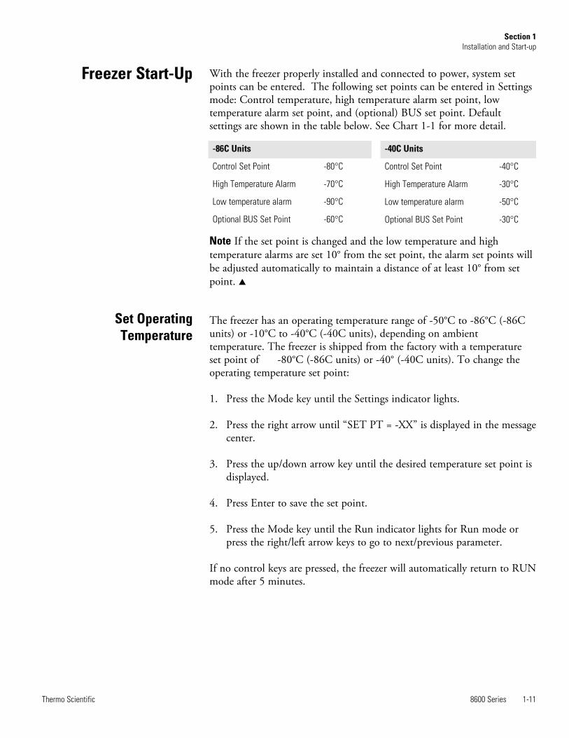
With the freezer properly installed and connected to power, system setpoints can be entered. The following set points can be entered in Settingsmode: Control temperature, high temperature alarm set point, lowtemperature alarm set point, and (optional) BUS set point. Defaultsettings are shown in the table below. See Chart 1-1 for more detail.
Note If the set point is changed and the low temperature and hightemperature alarms are set 10° from the set point, the alarm set points willbe adjusted automatically to maintain a distance of at least 10° from setpoint. s
The freezer has an operating temperature range of -50°C to -86°C (-86Cunits) or -10°C to -40°C (-40C units), depending on ambienttemperature. The freezer is shipped from the factory with a temperatureset point of -80°C (-86C units) or -40° (-40C units). To change theoperating temperature set point:
1. Press the Mode key until the Settings indicator lights.
2. Press the right arrow until “SET PT = -XX” is displayed in the messagecenter.
3. Press the up/down arrow key until the desired temperature set point isdisplayed.
4. Press Enter to save the set point.
5. Press the Mode key until the Run indicator lights for Run mode orpress the right/left arrow keys to go to next/previous parameter.
If no control keys are pressed, the freezer will automatically return to RUNmode after 5 minutes.
8600 Series 1-11Thermo Scientific
Section 1Installation and Start-up
Freezer Start-Up
-86C Units
Control Set Point -80°C
High Temperature Alarm -70°C
Low temperature alarm -90°C
Optional BUS Set Point -60°C
-40C Units
Control Set Point -40°C
High Temperature Alarm -30°C
Low temperature alarm -50°C
Optional BUS Set Point -30°C
Set OperatingTemperature

The high temperature alarm activates an audible/visual warning when thefreezer chamber temp reaches or exceeds the high temp alarm set point.
To set the high temperature alarm set point:
1. Press the Mode key until the Set indicator lights.
2. Press right arrow until “HI ALM = -XX” displays in message center.
3. Press the up or down arrow key until the desired high temperaturealarm set point is displayed.
4. Press Enter to save the setting.
5. Press the Mode key until the Run indicator lights or press the right orleft arrow to go to the next or previous parameter.
If no control keys are pressed, the freezer will automatically return to RUNmode after 5 minutes.
Note The high alarm set point must be set at least 5°C from the controlset point. s
Note At initial start-up, the high temperature alarm is disabled until thecabinet reaches set point or 12 hours elapse. s
The low temperature alarm activates an audible/visual warning when thefreezer chamber temp reaches or decreases below low temp alarm set point.
To set the low temperature alarm set point:
1. Press the Mode key until the Settings indicator lights.
2. Press right arrow until “LO ALM = -XX” displays in message center.
3. Press the up or down arrow key until the desired low temperaturealarm set point is displayed.
4. Press Enter to save the setting.
5. Press the Mode key until the Run indicator lights or press the right orleft arrow to go to the next or previous parameter.
If no control keys are pressed, the freezer will automatically return to RUNmode after 5 minutes.
Note The low alarm set point must be set at least 5°C from the control setpoint. s
1-12 8600 Series Thermo Scientific
Section 1Installation and Start-up
Set High TemperatureAlarm
Set Low TemperatureAlarm

An access code can be set to prevent unauthorized change of settings inCalibrate, Configuration and Settings mode. (An access code of 000 isrequired to make changes.) If the access code is not at the default 000, youcan not leave RUN mode without entering a code. See Section 3,Configuration for instructions on modifying the access code.
Run mode is the default mode for the freezer. The run mode displays thecabinet temperature on the temperature display and ‘SYSTEM OK’ on themessage center under normal operating conditions. In addition, the Runmode allows display of the following information:
LINE VOLTAGECOMPENSATED VOLTAGE* HSHX TEMPERATURE (heat exchanger temperature); -86C units
only
This information is scrolled individually by pressing the right arrow key.In each case, the message center returns to SYSTEM OK in 10 seconds ifno keys are pressed.
8600 Series 1-13Thermo Scientific
Section 1Installation and Start-up
Access Code
Run Mode

1-14 8600 Series Thermo Scientific
Section 1Installation and Start-up
Press MODEto light SETTINGS
indicator
Mode
Mode
SET PT = -XX
Numbers increasePress MODE to moveto CALIBRATEmode
Numbers decrease
Press Enter
to save settingScroll for Parameters
Scroll for Parameters
Mode HI ALM = -XXScroll for Parameters
Press to returnto previous parameter
Press to returnto previous parameter
Press to returnto previous parameter
Low AlarmSet Point
High AlarmSet Point
ControlSet Point
To Set:
Settings Mode
Numbers increase
Numbers decrease
Press Enter
to save setting
Numbers increase
Numbers decrease
Press Enter
to save setting
Mode
Press to returnto previous parameter
OptionalBack Up System
Set Point
Numbers increase
Numbers decrease
Press Enter
to save setting
SYSTEM OK
LO ALM = -XX
BACKUP = -XX

8600 Series 2-1Thermo Scientific
Section 2 Calibrate
Once the freezer has stabilized, the control probe may need to becalibrated. Calibration frequency is dependent on use, ambient conditionsand accuracy required. A good laboratory practice would require at least anannual calibration check. On new installations, all parameters should bechecked after the stabilization period.
Note Before making any calibration or adjustments to the unit, it isimperative that all reference instruments be properly calibrated. s
Plug a type T thermocouple reader into the receptacle located inside thelower door (see Figures 1-4 and 1-6). Compare the control temperatureset point to the temperature of the measuring device. See Chart 2-1 at theend of this section for more detail.
1. Press the Mode key until the Calibrate indicator lights.
2. Press the right arrow until “CONT T = -XX.X” appears in the messagecenter.
3. Press up/down arrow to match the display to calibrated instrument.
4. Press Enter to store calibration.
5. Press the Mode key to return to Run or the right/left arrow to go tonext/previous parameter.
Startup - Allow 12 hours for the temperature in the cabinet to stabilizebefore proceeding.
Already Operating - Allow at least 2 hours after the display reaches setpoint for temperature to stabilize before proceeding.
Note During calibration, the temperature display will not be available.
If no keys are pressed for approximately five minutes while in calibrationmode, the system will reset to Run mode.
Calibrate Mode
Calibrate Control Probe
Temperature Stabilization Periods

2-2 8600 Series Thermo Scientific
Section 2Calibrate
Press MODEto light CALIBRATE
indicator
Mode CONT T = -XX.X
Numbers increasePress MODE to moveto CONFIGURATIONmode
Numbers decrease
Press Enter
to save settingScroll for Parameters
Mode SAMPT = -XX.XScroll for Parameters
Press to returnto previous parameter
Press to returnto previous parameter
OptionalSample Probe
ControlProbe
To Calibrate:
Calibrate Mode
Numbers increase
Numbers decrease
Press Enter
to save setting
Chart 2-1
SYSTEM OK

8600 Series 3-1Thermo Scientific
Section 3 Configuration
Configuration Mode is used for testing and custom setup of the freezer.The configuration functions listed and described below may not benecessary in all applications, but are available if needed. See Chart 3-1 formore detail.
The high alarm test is used to verify that the high alarm will activate,should the freezer temperature equal or exceed the high alarm set point.
1. Press the Mode key until the Configuration indicator lights.
2. Press the right arrow until HI ALRM TEST is displayed in themessage center.
3. Press Enter to initiate the test.
The temperature on the display will begin to increase until the high alarmset point has been reached. The audible alarm will sound and the alarmindicator will flash. Press the Silence key to mute the alarm.
The low alarm test is used to verify the that low alarm will activate, shouldthe freezer temperature equal or become less than the low alarm set point.
1. Press the Mode key until the Configuration indicator lights.
2. Press the right arrow until LO ALRM TEST is displayed in themessage center.
3. Press Enter to initiate the test.
The temperature on the display will begin to decrease until the low alarmset point has been reached. The audible alarm will sound and the alarmindicator will flash. Press the Silence key to mute the alarm.
High Alarm Test
Low Alarm Test

3-2 8600 Series Thermo Scientific
Section 3Configuration
To test the charge of the freezer battery:
1. Press the Mode key until the Configuration indicator lights.
2. Press the right arrow until SYS BAT TEST is displayed in the messagecenter.
3. Press Enter to initiate the test.
TESTING BATT will display during the testing period. Upon completionof the test the message center will display BATT GOOD or BATT FAILWhen a test is failed, the audible alarm will sound, the alarm indicator andthe Low Battery indicator will light. Press the Silence key and the alarmindicator will go off. The Low Battery light will stay on until a futurebattery test is performed and passed.
To test the charge of the BUS battery:
1. Press the Mode key until the Configuration indicator lights.
2. Press the right arrow until BUS BAT TEST is displayed in the messagecenter.
3. Press Enter to initiate the test.
TESTING BATT will display during the testing period. Upon completionof the test the message center will display BBAT GOOD or BBAT FAIL Ifthis test fails, the audible alarm will sound, the alarm indicator and theLow Battery indicator will light. Press the Silence key. The audible alarmand alarm indicator will go off. The Low Battery light will stay on. If thetest fails, it is recommended to replace the BUS battery.
System Battery Test
BUS Battery Test

8600 Series 3-3Thermo Scientific
Section 3Configuration
This function, only available on freezers with the optional sample probe,allows the user to select which temperature is displayed in the temperaturedisplay window. The options are CONTROL or SAMPLE.
1. Press the Mode key until the Configuration indicator lights.
2. Press the right arrow until DISP CONTROL or DISP SAMPLE isdisplayed in the message center.
3. Press up/down arrow to toggle between the two display selections.
4. Press Enter to save.
If control probe is selected, the temperature display will be oncontinuously. If sample probe is selected, the temperature display will bepreceded with a letter ‘S’.
Should a high stage alarm have occurred, it may become necessary to clearthe alarm condition after the condition has been corrected.
1. Press the Mode key until the Configuration indicator lights.
2. Press the right arrow until CLR HS ALARM is displayed in themessage center.
3. Press Enter to clear the alarm.
To set the Access Code:
1. Press the Mode key until the Configuration indicator lights.
2. Press the right arrow until “SET ACC CODE” is displayed in themessage center.
3. Press Enter.
4. The message center will display ACC CODE = 000. Press the up ordown arrow key until the desired access code is displayed (000 - 999).Press the left or right arrow key to select digit 1, 2, 3.
Note The left and right arrow keys are used to move from the first throughthe third digits within the access code. s
5. Press Enter to save the setting
6. Press the Mode key until the Run indicator lights.A 3-digit AccessCode can be entered to avoid unauthorized personnel from changingthe set points, calibration, or configuration. A setting of 000 willbypass the access code. The factory setting is 000.
Display Temperature
Clear High Stage Alarm (-86C units only)
Set Access Code

If the freezer is configured for RS-485 communications, it will need tohave a unique identification address. This address is set through theConfiguration mode.
1. Press the Mode key until the Configuration indicator lights.
2. Press the right arrow until RS485ADDR is displayed in the messagecenter.
3. Press Enter. The message center will display 485 ADDR XX.
4. Press up/down arrow to select the appropriate address for the freezer(1 - 24).
5. Press Enter to save.
This function, which is only available on freezers with the optional backup system (BUS), allows the user to select which type of gas is injected intothe freezer chamber. The options are CO2 and LN2.
1. Press the Mode key until the Configuration indicator lights.
2. Press the right arrow until BUS TYPE CO2 or BUS TYPE LN2 isdisplayed in the message center.
3. Press up/down arrow to toggle between the two display selections.
4. Press Enter to save.
This function displays the coldest temperature recorded by the controlprobe.
This function displays the warmest temperature recorded by the controlprobe.
This function resets the cold and warm excursions.
3-4 8600 Series Thermo Scientific
Section 3Configuration
RS485 Address
Back Up System Type
Cold Excursion
Warm Excursion
Reset Excursion

8600 Series 3-5Thermo Scientific
Section 3Configuration
Press MODEto light
CONFIGURATIONindicator
Mode
Mode SYS BAT TEST
LOALRM TEST
Press MODE to moveto RUN mode
Press Enter
to initiate
testScroll for Parameters
Scroll for Parameters
Mode
HIALRM TEST
Scroll for Parameters
Press to returnto previous parameter
Press to returnto previous parameter
Press to returnto previous parameter
LowAlarmTest
HighAlarmTest
System BatteryTest
To Configure:
Mode
Scroll for Parameters
Chart 3-1
Press Enter
to initiate
test
Press Enter
to initiate
test
Press Enter
to initiate
test
Press to returnto previous parameter
OptionalBUS Battery
Test
BUS BAT TESTPress Enter
to initiate
test
Configuration Mode
SYSTEM OK

3-6 8600 Series Thermo Scientific
Section 3Configuration
Press Mode to exit.Press right or left arrowto move to next digit.
Numbers increase
Numbers decrease
Mode CLR HSALARMPress Enter to
clear the alarm
conditionScroll for Parameters
Press to returnto previous parameter
refer to previous page
Configuration Mode, Chart 3-1, Page 2 of 3
Clear HighStageAlarm
To Configure:
DISPCONTROL
CONTROLprobe
Press Enter to
save the settingMode
Scroll for Parameters
Press to returnto previous parameter
DisplayTemperature SAMPLE probe
Mode
Scroll for Parameters
ModePress Enter to
save the settingScroll for Parameters
Mode BUS TYPE CO2 Press Enter to
save the settingScroll for Parameters
Press to returnto previous parameter
OptionalBack Up
System Type
Mode RS485ADDR
Scroll through thevarious options.
Press Enter to
save the setting
Scroll for Parameters
Press to returnto previous parameter
RS-485Address
Type CO2
Type LN2
AccessCode
SETACC CODE XXX

8600 Series 3-7Thermo Scientific
Section 3Configuration
Mode WARM EX = -XXScroll for Parameters
Press to returnto previous parameter
refer to previous page
Configuration Mode, Chart 3-1, Page 3 of 3
WarmExcursion
To Configure:
COLD EX = -XXMode
Scroll for Parameters
Press to returnto previous parameter
ColdExcursion
Mode
Scroll for Parameters
Mode
Press Enter to
reset the cold
and warm
excursion values
Scroll for ParametersReset
Excursions
RST EXCUR
Press to returnto previous parameter


8600 Series 4-1Thermo Scientific
Section 4 Alarms
The 8600 Series freezer alarm system is shown below. When an alarm isactive, a message appears in the LED message center. Press the Silence keyto mute the audible alarm for the ringback period. The visual alarmcontinues until the freezer returns to a normal condition. The alarms aremomentary alarms only. If an alarm condition occurs and then returns tonormal, the freezer automatically clears the alarm condition and themessage center.
Description Message Delay Ringback Relay
No alarm condition exists SYSTEM OK ---- ---- ----
Power Failure POWER FAIL 1 min. 15 min. Yes
High Temperature Alarm TEMP IS HIGH 1 min. 15 min. Yes
Low Temperature Alarm TEMP IS LOW 1 min. 15 min. Yes
Door Ajar DOOR IS OPEN 1 min. 15 min. No
Low Battery* LOW BATTERY 1 min. 8 hours No
Low BUS Battery (optional) LOW BUS BATT 1 min 15 min. No
Control Probe Failure CNT PRB FLT 1 min. 15 min. Yes
Heat Exchanger Probe Failure ** HSHX PRB FLT 1 min. 15 min. No
Condenser Probe COND PRB FLT 1 min. 15 min. No
Sample Probe Failure (optional) SMPL PRB FLT 1 min. 15 min. No
High Stage System Failure ** HS SYST FAIL 1 min. 15 min. YES
Condenser Hot Condition HOT CONDENSR 1 min. none No
Wrong Power WRONG POWER 0 min. none YES
Micro Board Failure MICRO FAIL 0 min. 15 min. YES
All alarm delays and ringback times are +30 seconds.*The automatic battery test runs immediately on power-up, then every 8 hours thereafter.** -86C units only
Table 4-1. Alarms

4-2 8600 Series Thermo Scientific
Section 4Alarms
This condition is created when the high stage compressor and fans run for30 minutes and are not capable of cooling the interstage heat exchanger tothe proper temperature. Under this condition, the high stage compressorand fans will turn off after 30 minutes and an audible and visual alarm willoccur along with the "HS SYST FAIL" message in the LED messagecenter.
When multiple alarm conditions occur, active messages are displayed in themessage center one at a time, updating at 5 second intervals. PressingSilence during multiple alarms causes all active alarms to be silenced and toring back in 15 minutes.
An internal communication failure has occurred with the micro board.During this alarm, the compressor(s) attempt to run continuously.However, with this type of failure, freezer operation becomesundependable.
Communication between the micro board and the display board has beenlost. Under this condition, the visual alarm flashes along with dashes in thetemperature display (----). Contact Technical Services.
High Stage System FailureAlarm (-86C units only)
Multiple Alarms
Micro Board FailureAlarm
Lost Communication

8600 Series 4-3Thermo Scientific
Section 4Alarms
Error High End Message Notes
Er00 “INV. MODEL”
Name: Improper model selected.Description: Indicates that DIP SW3 has not selected a proper model or can’t be accessed properly.Response: Display shows “Er00” and will not start-up until a proper model is selected. Contact TechnicalServices.
ErA1 “ NO FREQUENCY” This error condition will prevent peripherals (fans, compressors, etc.) from powering up with the incorrectvoltage.Name: Voltage/Frequency failureDescription: Indicates the measured RMS line voltage did not agree with the logic level sensed by themicros provided by the installed high voltage PCB; or the measured RMS voltage is not within a tolerablerange (<180VAC < 270 for 230VAC unit / <85 VAC < 160 for 115VAC unit); or the frequency measured over 10cycles was not within a tolerable range (55 Hz < Freq < 70 Hz for 60 Hz units / 40 Hz < Freq < 55 Hz for 50 Hzunits)Response: This condition is checked at power on reset and if it is active the unit will NOT power up. Theunit will indefinitely display “Er_1” in the display and continue to monitor the frequency and voltage.Furthermore, the audible alarm will sound. Other startup error messages may be displayed prior to this mes-sage; however, the system will stop the startup sequence for this condition.ErA1 .. No pulses (zero crossings) detected to determine frequency (50 / 60 Hz)ErC1 .. Frequency detected is below 50 HzErd1 .. Frequency detected is above 60 Hz (Possible noise spikes on supply voltage)ErE1 .. Unit is 230V and the voltage detected is below the low limit (180VRMS)ErF1 .. Unit is 230V and the voltage detected is above the high limit (260VRMS)Erg1 .. Unit is 115V and the voltage detected is below the low limit (85VRMS)ErH1 .. Unit is 115V and the voltage detected is above the high limit (160VRMS)
ErC1 “FREQ <50Hz”
Erd1 “FREQ >60Hz”
ErE1 “VAC < 180V”
ErF1 “VAC > 260V”
Erg1 “VAC < 85V”
ErH1 “VAC > 160V”

4-4 8600 Series Thermo Scientific
Section 4Alarms
Error(cont.) High End Message Notes
Er02 “CNT PRB FLT”
Name: Control (Cabinet) Sensor FailureDescription: This condition indicates that the control sensor has failed to produce a valid reading for >12consecutive reads (~60 seconds).Response: The unit will stage both compressors on (if necessary) and the unit will attempt to head to bot-tom out. If the sensor recovers, the system will begin to operate normally and respond to the temperaturefeedback. The remote alarm contacts will become active regardless of the key position for this mode of fail-ure. ‘Er02’ will be added to the main display queue and the last valid cabinet temperature value will not bedisplayed
Er03“HSHX PRB FLT”-86C units only
Name: Heat Exchange Sensor FailureDescription: This condition indicates that the heat exchange sensor has failed to produce a valid readingfor >12 consecutive reads (~60 seconds).Response: The display will show “Er03” only when the button sequence to read the heat exchange sensoris depressed.
Er05 N/A
Name: Display Firmware Integrity FailureDescription: The display firmware has failed to pass its CRC CCITT checksum integrity test.Response: The display performs this check at startup and the display board will fail to startup with out anyerror indication if it does not pass this at power on.
Er06 N/A
Name: Micro Firmware Integrity FailureDescription: The micro firmware has failed to pass its CRC CCITT checksum integrity test.Response: This is checked at power on reset and the “Er06” will be displayed for ~10 seconds at startup ifthis condition exists.
Er07 “MICRO FAIL”
Name: Micro Fail - CS5521 SPI Failure / UISR FailureDescription: This condition indicates a micro board failure due to either the SPI bus is unable to communi-cate with the ADC device or a UISR event caused the microcontroller to be in an unstable state.Response: The unit will try to recover from this fault three times by a hardware reset of the micro board. Inthe event that the system couldn’t rectify the issue, the following sequence of events will occur:
1. Remote alarm contacts will become active.2. Buzzer will annunciate audibly and will have a ringback of 15 minutes.3. “Seven segment” display will show “Er07”.4. The -86C system will have 10 minute staging between the high stage compressor and the low stage
compressor activation (-40C units will activate the compressor).5. The system will go to bottom out temperatures.

8600 Series 4-5Thermo Scientific
Section 4Alarms
Error(cont.) High End Message Notes
Er09 N/AName: Stuck ButtonDescription: This condition indicates that the display board has a stuck button.Response: The Er09 will show on the display periodically.
Er11 “COND PRB FLT”
Name: Condenser Probe Sensor FailureDescription: This condition indicates that the condenser probe sensor has failed to produce a valid readingfor >12 consecutive reads (~60 seconds).Response: The display shows “Er11”.
N/A “SMPL PRB FLT”
Name: Sample Probe Sensor FailureDescription: This condition indicates that the sample probe sensor has failed to produce a valid reading for>12 consecutive reads (~60 seconds).Response: The message center shows “SMPL PRB FLT”.
dErr N/A This is a general display error in which the value being displayed can not be represented withinthe characters provided.
(fourdashes)---- indisplay
N/AName: Lost CommunicationDescription: Communication between the micro board and the display board has been lost. Under this con-dition, the visual alarm flashes along with dashes in thetemperature display (----). Contact Technical Services.


8600 Series 5-1Thermo Scientific
Section 5 Maintenance
Wipe down the freezer exterior using soap and water and a general uselaboratory disinfectant. Rinse thoroughly with clean water and dry with asoft cloth.
Caution Avoid the excessive use of water around the control area due tothe risk of electrical shock. Damage to the controls may also result. s
The air filter should be cleaned a minimum of four times per year.
1. Open the lower panel door by grasping the handle.
2. Locate the grille on the door. See Figures 1-6 and 1-8. Grasp themiddle of the grille material and gently pull out to remove.
3. Wash the filter material using water and a mild detergent.
4. Dry by pressing between two towels.
5. Install the filter back into the grille and close the door.
Depending upon environmental conditions, the filter may need to becleaned or replaced more frequently. If the filter becomes torn orexcessively dirty, a replacement can be purchased from Thermo. Orderpart number 398216 for 3 cu. ft. units, or 398217 for 13, 17, and 20 cu.ft. units.
The condenser should be cleaned a minimum of once per year.
1. Open the lower panel door by grasping the handle. See Figures 1-6and 1-8.
2. Using a vacuum cleaner, exercising care to not damage the condenserfins, clean the condenser.
Depending upon environmental conditions, the condenser may need to becleaned more frequently.
Clean Air Filter
Clean Condenser

5-2 8600 Series Thermo Scientific
Section 5Maintenance
1. Remove all product and place it in another freezer.
2. Turn the unit off and disconnect it from the power source.
3. Turn off the battery switch (O). See Figures 5-1 and 5-2.
4. Open the lid and remove sub-lids. Place towels on the chamber floor.
5. Allow the frost to melt and become loose. Remove with a soft cloth.
7. After defrosting is complete, clean the interior with a non-chloridedetergent. Rinse thoroughly with clean water and dry with a soft cloth.
8. Plug unit in and turn power switch on.
9. Turn the battery power switch to Standby mode ( ).
10. Allow the freezer to operate empty overnight before reloading theproduct.
The lid gasket should be cleaned a minimum of once per month. Using asoft cloth, remove any frost build-up from the gasket, sub-lids and lids.The clean gasket alarm occurs every three months as a reminder to removefrost build-up from the gasket and doors. Press the Silence key to mute theaudible alarm. The lid gasket may need to be cleaned more frequently ifdirt or excessive frost build-up prevents the door from closing properly.
The following instructions describe the battery replacement procedure forspecific models.
1. Open the lower panel door by grasping the handle and pulling.
2. Locate the battery power switch (Figure 5-1). Turn the battery powerswitch to the Off position (O).
3. Remove the four screws holding the recorder bezel to gain access to thebattery.
4. Remove the three nuts securing the battery bracket. See Figure 5-1.
5. Remove the bracket and old battery. Discard properly. Install the newbattery and secure.
Defrost Chamber
Clean Lid Gasket
Replace Battery(s)
All Models Except 3 cu ft

8600 Series 5-3Thermo Scientific
Section 5Maintenance
6. Reconnect the battery (red topositive and black tonegative).
7. Replace the recorder bezel.
8. Turn the battery powerswitch to Standby mode ( ).
9. Close lower panel door.
1. Open the lower panel door bylocating the handle on theunderside of the lower paneldoor and pulling.
2. Locate the battery power switch(Figure 5-2). Turn the batterypower switch to the Offposition (O).
3. Remove the two nuts securingthe battery bracket. See Figure5-2.
5. Remove the bracket and oldbattery. Discard properly. Install the new battery and secure.
6. Reconnect the battery (red to positive and black to negative).
7. Replace the recorder bezel.
8. Turn the battery power switch to Standby mode ( ).
9. Close lower panel door.
Note For a consistent and dependable charge, replace the battery every 2years. Replacement batteries must be rechargeable and are available fromThermo. Refer to the parts list for stock number and description of thereplacement batteries (P/N 400159). Dispose of the used batteries in a safemanner and in accordance with good environmental practices. s
microboard
battery
bracket
batteryswitch
probeaccessport
Figure 5-1. Battery and Switch location
3 cu ft Models
O
aaaaaaaaaaaaaaaaaaaaaaaaaaaaaaaaaaaaaaaaaaaaaaaaaaaaaaaaaaaaaaaaaaaaaaaaaaaaaaaaaaaaaaaaaaaaaaaaaaaaaaaaaaaaaaaaaaaaaaaaO
System
battery
Battery
switch
Thermocouple
interconnect jack
Figure 5-2. Battery and Switch location
All Models Except 3 cu ft(continued)

5-4 8600 Series Thermo Scientific
Section 5Maintenance
All Models except 3 cu ft (Figure 5-1):
1. Locate the power switch on the back of the unit. Turn the switch off.(O).
2. Open the lower door on the front left corner of the sidecar. Turn offthe battery switch (O).
3. Remove all the screws from the side panel, except the lower ones. Justloosen these and lift the panel off.
4. The battery is rectangular in shape, located above the compressorcompartment, to the right and behind the relay box. Remove the threewingnuts that secure the cover on the battery. Remove the cover.
5. Remove the battery from the mounting bracket.
6. Disconnect the red and black wires from the battery.
7. Use a voltmeter set to DC volts. Matching the wire colors, connect themeter to the battery.
8. If the voltage reads less than 10.8 volts, replace the battery. If above10.8, re-install as previously.
9. Re-install side panel. Turn the battery power switch to Standby mode( ), then close lower door. Turn power switch On.
3 cu ft Models (Figure 5-2):
1. To gain access to the battery, open the lower door by grasping thebottom left corner. The battery is rectangular in shape, located on theleft sideof the filter compartment.
2. Directly above the battery(s) is the battery power switch. Turn thebattery power switch to the off position (O).
3. Remove the three wingnuts that secure the cover on the battery.Remove the cover.
4. Remove the battery from the mounting bracket.
5. Disconnect the red and black wires from the battery.
6. Use a voltmeter set to DC volts. Matching the wire colors, connect themeter to the battery.
7. If the voltage reads less than 10.8 volts, replace the battery. If above10.8, re-install as previously.
8. Turn the battery power switch to Standby mode ( ).
9. Close lower door.
Check Battery(s)

8600 Series 5-5Thermo Scientific
Section 5Maintenance
Defrost the unit as previously described. This prepares the unit for storage.Turn Off the battery power switch (O). Turn Off the freezer powerswitch.
Note If the unit has been in service, turn it off and disconnect the powercord connector before proceeding with any maintenance. s
Prepare Unit forStorage

5-6 Model 8700 Series Thermo Scientific
Section 5Maintenance
PREVENTIVE MAINTENANCEFreezers
Your equipment has been thoroughly tested and calibrated before shipment. Regular preventive maintenance is important to keep yourunit functioning properly. The operator should perform routine cleaning and maintenance on a regular basis. For maximumperformance and efficiency, it is recommended that the unit be checked and calibrated periodically by a qualified service technician.
The following is a condensed list of preventive maintenance requirements. See the specified section of the instruction manual forfurther details.
We have qualified service technicians, using NIST traceable instruments, available in many areas. For more information on PreventiveMaintenance or Extended Warranties, please contact the Technical Services Department.
Cleaning and calibration adjustment intervals are dependent upon use, environmental conditions and accuracy required.
Tips:
• Fill an upright by starting at the bottom near the probe and add racks to one shelf at a time. Allow freezer to recover to set pointbetween shelves.
• Fill a chest by starting at the left side near the probe. Filling with room temperature racks will result in a long pull-down time.
• Fill unit with frozen product to help overall performance; frozen water jugs, for example.
• Always make certain the vacuum relief port is free of frost and ice, to allow for timely re-entry into the freezer after a dooropening.
Action Monthly Yearly Every2 Years
Verify ambient temperature, <90°F 4
Check and clean probe cover, gaskets, hinges and lid(s) of ice and snow. SeeFigure 1-5 for probe location. See “Clean Lid Gasket”.
4
More frequent cleaning may berequired, depending on use andenvironmental conditions.
Check air filter. Clean or replace as needed. See “Clean Air Filter”. 4 4X
Check alarm back-up battery. See “Connect Unit to Electrical Power” inSection 1 and “Replace Battery” in Section 5.
4**Replace
Check condenser fan motor for unusual motor noise or vibration. 4
* Verify and document calibration, at the minimum, annually. See Section 2Calibration.
* Clean condenser compartment and vacuum off condenser. See “CleanCondenser” in Section 5.
4
Recommended Maintenance *Back-up System - inject test & battery. SeeSection 6.
4
4* Qualified service technicians only** Dispose of properly, according to all state and federal regulations.

Section 6 Factory Installed Options
Note Before installation of BUS components, make sure the power to thefreezer is disconnected, the battery switch is turned off (O) and the freezerhas warmed to ambient temperature. s
The built-in BUS (back up system) will keep the freezer chambertemperature below the critical level in the event of a power or equipmentfailure. If power to the freezer fails, or temperature increases to the back upalarm set point, the BUS injects liquefied gas into the chamber to keep thechamber temperature within the specified range.
The BUS operates on an internal 12-volt, rechargeable battery which iskept charged during normal operation by the integral battery charger.
1. Locate the mounting hole for installing the injection tee assembly. SeeFigure 6-1.
Note Cover open end of injection assembly with tape to keep insulationfrom entering the nipple. s
2. Slide 3/8” flatwasher over open end of nipple.
3. Insert the covered end of the injection assembly through exterior hole.
8600 Series 6-1Thermo Scientific
Back Up System (BUS)- P/N 1950445, 1950447
Install Injection Assembly
Mounting hole for injection tee
Figure 6-1. Mounting location

4. Remove the tape covering the end of the nipple and install the 1/8”NPT brass tee on the open end of the nipple. Place Permagum sealantbetween the brass tee and the interior top.
5. Go to the interior and seal around injection assembly with Permagum.
6. Install the transfer hose connecting one end to the injection assembly,the other end to the solenoid valve. Install the solenoid valve to thesupply source. The solenoid mounting bracket is not required and maybe discarded.
Note When selecting a CO2 supply cylinder, it must be equipped with asiphon tube. s
1. Plug the solenoid/probe connector into the BUS connection. Loop theprobe wire back into the base/side car. Secure the connector with ascrew on the ends of the connector. The connector is keyed.
2. Route the temperature probe through the probe port. The probe portis located in the upper right corner (viewed from the side) of 12.7 and20 cu. ft. models, and in the lower right corner (viewed from the back)of 3.0 cu. ft. models.
6-2 8600 Series Thermo Scientific
Section 6Factory Installed Options
Figure 6-2. Injection Assembly
Install Temperature Probe
probewires
Figure 6-3. Probe and Solenoid Connections
Install Injection Assembly(continued)

8600 Series 6-3Thermo Scientific
Section 6Factory Installed Options
3. Carefully remove the existing Permagum sealant from around theprobe port opening.
4. Open the freezer lid and locate the probe cover on the upper front leftwall. Remove the two Phillips head screws securing the probe cover(see Figure 6-5).
5. Route the BUS probe through the probe port, approximately 12”.Secure the back-up probe to the temperature probe using a small tiewrap (Figure 6-5).
6. Seal around the interior and exterior opening of the probe port withPermagum sealant.
7. Reinstall the probe cover (Figure 6-5).
microboard
battery
bracket
batteryswitch
probeaccessport
Figure 6-4. Probe Access Port
Figure 6-5. Probe location
Install Temperature Probe(continued)

1. Carefully coil the extra probe lead in the compressor compartment,and secure it to the compartment wall with a tie wrap and tie wrapanchor provided. Additional tie wraps and anchors may be used tosecure the probe lead to the exterior back wall of the freezer.
2. Loosen the terminal screws on the solenoid. Slide the spade lugconnectors under the screws and tighten to secure.
3. Connect power to the freezer. Turn the freezer On, with battery switchOff (O).
a. The Solenoid Engaged light on the BUS control panel illuminates(no injection occurs). This light stays on until the unit is belowBUS setpoint.
b. The Low Battery indicator may also illuminate.
4. Turn the battery switch to Standby mode ( ) to charge both batteries.
The following section describes the configuration and operation of theBUS.
Warning When activated, this unit injects liquid nitrogen or carbondioxide. Liquid nitrogen can cause serious freezing (frostbite) if it comes incontact with unprotected skin or eyes. Nitrogen suppresses oxygen levelsand may cause suffocation if area is not well ventilated. Refer to AppendixA for the proper handling of liquid LN2. s
Caution Make sure the pressure relief valve on any LN2 tank is adjusted to30 PSI maximum blow-off. s
Warning Carbon dioxide gas suppresses oxygen levels and may causesuffocation if area is not well ventilated. Refer to “Handling Liquid CO2 inAppendix B of this manual. s
6-4 8600 Series Thermo Scientific
Section 6Factory Installed Options
Connect Probe/SolenoidHarness
BUS Control Panel
Power Low Battery Solenoid Engaged Press to test
Backup System
Figure 6-6. BUS Control Panel

Power - indicates the unit has AC power.
Low Battery - battery charge is low. The battery needs replaced orrecharged.
Solenoid Engaged - BUS has opened the solenoid so it can inject gas (CO2
or LN2).
Press-To-Test - Activates the solenoid and injects LN2 or CO2 into thefreezer chamber as long as the button is depressed. The solenoid engagedindicator should light. If the Low Battery indicator lights during the test,replace the BUS battery.
Note The solenoid will not engage if lid is open. s
Caution The back-up system is designed to inject CO2 or LN2. In theunlikely event of back-up system failure, the back-up system will activateand allow CO2 or LN2 to flow until stopped manually or is manually shutoff. s
The optional BUS can be configured for LN2 or CO2 supply. Section 3 -Configuration contains instructions for setting the BUS type.
The optional back up system is designed to inject CO2 or LN2 into thefreezer compartment if the temperature rises above back up system setpoint. To set the BUS set point:
1. Press the Mode key until the Settings indicator lights.
2. Press right arrow until “BACKUP = -XX” displays in message center.
3. Press up or down arrow key until desired BUS set point is displayed.
4. Press Enter to save the setting.
5. Press the Mode key until the Run indicator lights, or press the right orleft arrow to go to the next or previous parameter.
If no control keys are pressed, the freezer will automatically return toRUN mode after 5 minutes.
8600 Series 6-5Thermo Scientific
Section 6Factory Installed Options
Configure Optional Back UpSystem (BUS)
BUS Control Panel(continued)
Set Optional BUS SetPoint

Warning Changing operating temp set point can affect BUS set point.BUS set point self adjusts to maintain a temp of at least 10°C above theoperating temp set point. s
Note The BUS set point cannot be set any colder than the hightemperature alarm set point. (See Section 1 - Setting the HighTemperature Alarm). If the back-up system is installed with CO2, then -65°C is the coldest BUS set point that can be used (if the cabinet set pointis -75°C or colder). s
After the freezer has stabilized and both batteries are fully charged, theBUS can be tested to verify proper operation.
1. Disconnect the AC power to the freezer by turning power switch off.
2. As the freezer warms up, verify the BUS injects at the desiredtemperature. Displayed temperature may vary by a few degrees frominject temperature due to the differences in probe locations.
3. Recommended Maintenance - Monthly maintenance action to checkCO2 or LN2 back-up system operation, alarms and battery voltage.
To disconnect the freezer back-up from the gas supply:
1. Close the supply valve.
2. Depress the test button on the Back-Up System control box to removethe gas from the line.
3. Slowly disconnect the fitting assembly from the supply (in the eventthat any gas remains in the line).
6-6 8600 Series Thermo Scientific
Section 6Factory Installed Options
Set Optional BUS SetPoint (continued)
Disconnect FittingAssembly, Transfer Hose
1 23
9-volt battery
Green LED
Program selection and
calibration buttons
1 2
3
Figure 6-7. Recorder Details
Test the BUSOperation
Chart Recorder

The following section describes the set up and operation of the optionalchart recorder.
1. Open the plastic door of the recorder and press button #3 until thepen begins to move outward.
2. Unscrew the knob at the center of the chart and remove the paper.
3. Install the new chart paper, position the paper to the correct time lineand replace the knob.
4. Remove the cap from the felt pen and press button #3.
The chart recorder contains eight temperature ranges and is factory-programmed for the freezer. To change the recorder range:
1. Press and hold button #3 for one second, then let the pen move off thechart paper.
2. Press and hold for five seconds either button #1 or button #2.
3. Release the button and the green LED willbegin to flash. Count the number of flashesto determine the present program setting.
4. To change the program setting, press theleft or right arrows to increase or decreasethe count.
5. When the desired program number isflashing, press button #3 to bring the penarm back onto the chart. Recording willbegin in the new program.
The recorder must be in service for 24 hours before performing thefollowing calibration procedure.
1. Place an accurate thermometer in the chamber next to the recorderprobe.
2. Temperature probes for the recorder are located in the left front cornerof the freezer chamber (Figure 1-4).
3. After about three minutes, compare the thermometer reading with thechart recorder reading.
8600 Series 6-7Thermo Scientific
Section 6Factory Installed Options
Install Chart Paper
Change Program
Program From To
1 -40 30°C
2 0 60°C
3 -100 38°C
4 -5 50°C
5 0 100°C
6 -100 200°C
7 -115 50°C
8 -10 70°C
Calibrate Chart Recorder

4. If an adjustment is necessary, press the #1 button to move the pen tothe left or the #2 to move the pen to the right. The button must beheld about five seconds before the pen begins to move. Release thebutton when the pen position matches the thermometer.
Note The felt-tip pen on the recorder requires periodic replacement.Usually the ink will appear to fade before replacement becomes necessary.Additional pen tips may be purchased from Thermo. s
6-8 8600 Series Thermo Scientific
Section 6Factory Installed Options
Calibrate Chart Recorder(continued)

Section 7 Specifications
8600 Series 7-1Thermo Scientific
Number (Model) 813CV (8702) 813CD (8703) 813CA (8704)
Temperature Range -50°C(-58°F) to -86°C(-123°F) in an 18C to 32C * (64.4F to 89.6F) ambient
Exterior Dimensions72.0”W x 40.5” H x 33.4” F-B(182.9cm x 102.9cm x 84.8cm)Add 7.9” (20.1cm) to F-B for wall spacer/handle.
Interior Dimensions42.5”W x 28.0”H x 18.5” F-B(108.0cm x 71.1cm x 47.0cm)
Capacity 12.7 cu. ft. (360 liters)
Refrigeration Cascade system, (2) hermetically-sealed compressors
Insulation Non CFC, foamed-in-place urethane: 5.0" (12.7cm) cabinet; 2.0" (5.0cm) lid; 1.0" (12.5cm) sub-lids
Electrical - nominalvoltage ±10%
230VAC, 1 PH, 50 Hz, 12.0 FLAOperating Range: 208VAC-240VAC
230VAC, 1 PH, 60 Hz, 12.0 FLAOperating Range: 208VAC-240VAC
120VAC, 1 PH, 60 Hz, 16.0 FLAOperating Range: 108VAC-130VAC
Breaker Requirements15 Amp Dedicated Circuit, 15 Amp Time Delay Breaker
15 Amp Dedicated Circuit, 15 Amp Time Delay Breaker
20 Amp Dedicated Circuit,20 Amp Time Delay Breaker
Shipping Weight 716 lbs. (325 kg)
Number (Model) 803CA (8700) 803CV (8701)
Temperature Range -50°C(-58°F) to -86°C(-123°F) in an 18C to 32C * (64.4F to 89.6F) ambient
Exterior Dimensions28.5”W x 43.8” H x 29.9” F-B(72.4cm x 111.3cm x 75.9cm)Add 7.9” (20.1cm) to F-B for wall spacer/handle.
Interior Dimensions18.5”W x 16.5”H x 18.5” F-B(47.0cm x 41.9cm x 47.0cm)
Capacity 3.0 cu. ft. (84.9 liters)
Refrigeration Cascade system, (2) hermetically-sealed compressors
InsulationNon CFC, foamed-in-place urethane: 5.0" (12.7cm) cabinet; 2.0" (5.0cm) lid;1.0" (12.5cm) sub-lids
Electrical - nominalvoltage ±10%
120VAC, 1 PH, 60 Hz, 10.5 FLAOperating Range: 108VAC-130VAC
230VAC, 1 PH, 50 Hz, 5.4 FLAOperating Range: 208VAC-240VAC
Breaker Requirements15 Amp Dedicated Circuit, 15 Amp Time Delay Breaker
15 Amp Dedicated Circuit,15 Amp Time Delay Breaker
Shipping Weight 432 lbs. (196 kg)

7-2 8600 Series Thermo Scientific
Section 7Specifications
Number (Model) 817CA (8705) 817CV (8706) 817CD (8707)
Temperature Range -50°C(-58°F) to -86°C(-123°F) in an 18C to 32C * (64.4F to 89.6F) ambient
Exterior Dimensions87.6”W x 40.5” H x 33.8” F-B(222.5cm x 102.9cm x 85.9cm)Add 7.9” (20.1cm) to F-B for wall spacer/handle.
Interior Dimensions58.8”W x 28.0”H x 18.5” F-B(149.4cm x 71.1cm x 47.0cm)
Capacity 17.0 cu. ft. (481.4 liters)
Refrigeration Cascade system, (2) hermetically-sealed compressors
Insulation Non CFC, foamed-in-place urethane: 5.0" (12.7cm) cabinet; 2.0" (5.0cm) lid; 1.0" (12.5cm) sub-lids
Electrical - nominalvoltage ±10%
120VAC, 1 PH, 60 Hz, 16.0 FLAOperating Range: 108VAC-130VAC
230VAC, 1 PH, 50 Hz, 12.0 FLAOperating Range: 208VAC-240VAC
230VAC, 1 PH, 60 Hz, 12.0 FLAOperating Range: 208VAC-240VAC
Breaker Requirements20 Amp Dedicated Circuit,20 Amp Time Delay Breaker
15 Amp Dedicated Circuit,15 Amp Time Delay Breaker
15 Amp Dedicated Circuit,15 Amp Time Delay Breaker
Shipping Weight 821 lbs. (372 kg)
Number (Model) 820CV (8708) 820CD (8709) 820CA (8710)
Temperature Range -50°C(-58°F) to -86°C(-123°F) in an 18C to 32C * (64.4F to 89.6F) ambient
Exterior Dimensions96.0”W x 40.5” H x 33.4” F-B(243.8cm x 102.9cm x 84.8cm)Add 7.9” (20.1cm) to F-B for wall spacer/handle.
Interior Dimensions66.5”W x 28.0”H x 18.5” F-B(168.9cm x 71.1cm x 47.0cm)
Capacity 20.0 cu. ft. (566.3 liters)
Refrigeration Cascade system, (2) hermetically-sealed compressors
Insulation Non CFC, foamed-in-place urethane: 5.0" (12.7cm) cabinet; 2.0" (5.0cm) lid; 1.0" (12.5cm) sub-lids
Electrical - nominalvoltage ±10%
230VAC, 1 PH, 50 Hz, 12.0 FLAOperating Range: 208VAC-240VAC
230VAC, 1 PH, 60 Hz, 12.0 FLAOperating Range: 208VAC-240VAC
120VAC, 1 PH, 60 Hz, 16.0 FLAOperating Range: 108VAC-130VAC
Breaker Requirements15 Amp Dedicated Circuit, 15 Amp Time Delay Breaker
15 Amp Dedicated Circuit, 15 Amp Time Delay Breaker
20 Amp Dedicated Circuit,20 Amp Time Delay Breaker
Shipping Weight 833 lbs. (378 kg)

8600 Series 7-3Thermo Scientific
Section 7Specifications
Number (Model) 713CV (8722) 713CD (8727) 713CA (8728)
Temperature Range -10°C (-14°F) to -40°C (-40°F) in an 18C to 32C * (64.4F to 89.6F) ambient
Exterior Dimensions72.0”W x 40.5” H x 33.4” F-B(182.9cm x 102.9cm x 84.8cm)Add 7.9” (20.1cm) to F-B for wall spacer/handle.
Interior Dimensions42.5”W x 28.0”H x 18.5” F-B(108.0cm x 71.1cm x 47.0cm)
Capacity 12.7 cu. ft. (360 liters)
Refrigeration Hermetically-sealed compressor
Insulation Non CFC, foamed-in-place urethane: 5.0" (12.7cm) cabinet; 2.0" (5.0cm) lid; 1.0" (12.5cm) sub-lids
Electrical - nominalvoltage ±10%
230VAC, 1 PH, 50 Hz, 3.0 FLAOperating Range: 208VAC-240VAC
230VAC, 1 PH, 60 Hz, 3.0 FLAOperating Range: 208VAC-240VAC
120VAC, 1 PH, 60 Hz, 6.0 FLAOperating Range: 108VAC-130VAC
Breaker Requirements15 Amp Dedicated Circuit, 15 Amp Time Delay Breaker
15 Amp Dedicated Circuit, 15 Amp Time Delay Breaker
20 Amp Dedicated Circuit,20 Amp Time Delay Breaker
Shipping Weight 716 lbs. (325 kg)
Number (Model) 703CA (8718) 703CV (8719)
Temperature Range -10°C (-14°F) to -40°C (-40°F) in an 18C to 32C * (64.4F to 89.6F) ambient
Exterior Dimensions28.5”W x 43.8” H x 29.9” F-B(72.4cm x 111.3cm x 75.9cm)Add 7.9” (20.1cm) to F-B for wall spacer/handle.
Interior Dimensions18.5”W x 16.5”H x 18.5” F-B(47.0cm x 41.9cm x 47.0cm)
Capacity 3.0 cu. ft. (84.9 liters)
Refrigeration Hermetically-sealed compressor
InsulationNon CFC, foamed-in-place urethane: 5.0" (12.7cm) cabinet; 2.0" (5.0cm) lid;1.0" (12.5cm) sub-lids
Electrical - nominalvoltage ±10%
115VAC, 1 PH, 60 Hz, 6.0 FLAOperating Range: 108VAC-130VAC
230VAC, 1 PH, 50 Hz, 3.0 FLAOperating Range: 208VAC-240VAC
Breaker Requirements15 Amp Dedicated Circuit, 15 Amp Time Delay Breaker
15 Amp Dedicated Circuit,15 Amp Time Delay Breaker
Shipping Weight 395 lbs. (179 kg)

Section 7Specifications
7-4 8600 Series Thermo Scientific
Number (Model) 717CV (8730) 717CD (8731) 717CA (8733)
Temperature Range -10°C (-14°F) to -40°C (-40°F) in an 18C to 32C * (64.4F to 89.6F) ambient
Exterior Dimensions87.6.0”W x 40.5” H x 33.8” F-B(222.5cm x 102.9cm x 85.9cm)Add 7.9” (20.1cm) to F-B for wall spacer/handle.
Interior Dimensions58.8”W x 28.0”H x 18.5” F-B(149.4cm x 71.1cm x 47.0cm)
Capacity 17.0 cu. ft. (481.4 liters)
Refrigeration Hermetically-sealed compressor
Insulation Non CFC, foamed-in-place urethane: 5.0" (12.7cm) cabinet; 2.0" (5.0cm) lid; 1.0" (12.5cm) sub-lids
Electrical - nominalvoltage ±10%
120VAC, 1 PH, 60 Hz, 9.0 FLAOperating Range: 108VAC-130VAC
230VAC, 1 PH, 50 Hz, 7.0 FLAOperating Range: 208VAC-240VAC
230VAC, 1 PH, 60 Hz, 7.0 FLAOperating Range: 208VAC-240VAC
Breaker Requirements20 Amp Dedicated Circuit,20 Amp Time Delay Breaker
15 Amp Dedicated Circuit,15 Amp Time Delay Breaker
15 Amp Dedicated Circuit,15 Amp Time Delay Breaker
Shipping Weight 764 lbs. (347 kg)
Number (Model) 720CV (8734) 720CD (8736) 720CA (8737)
Temperature Range -10°C (-14°F) to -40°C (-40°F) in an 18C to 32C * (64.4F to 89.6F) ambient
Exterior Dimensions96.0”W x 40.5” H x 33.4” F-B(243.8cm x 102.9cm x 84.8cm)Add 7.9” (20.1cm) to F-B for wall spacer/handle.
Interior Dimensions66.5”W x 28.0”H x 18.5” F-B(168.9cm x 71.1cm x 47.0cm)
Capacity 20.0 cu. ft. (566.3 liters)
Refrigeration Hermetically-sealed compressor
Insulation Non CFC, foamed-in-place urethane: 5.0" (12.7cm) cabinet; 2.0" (5.0cm) lid; 1.0" (12.5cm) sub-lids
Electrical - nominalvoltage ±10%
230VAC, 1 PH, 50 Hz, 6.5 FLAOperating Range: 208VAC-240VAC
230VAC, 1 PH, 60 Hz, 6.5 FLAOperating Range: 208VAC-240VAC
120VAC, 1 PH, 60 Hz, 10.0 FLAOperating Range: 108VAC-130VAC
Breaker Requirements15 Amp Dedicated Circuit, 15 Amp Time Delay Breaker
15 Amp Dedicated Circuit, 15 Amp Time Delay Breaker
20 Amp Dedicated Circuit,20 Amp Time Delay Breaker
Shipping Weight 776 lbs. (352 kg)

Section 7Specifications
CertificationsDeclaration of Conformity is available from the factory
Safety SpecificationsIndoor Use OnlyAltitude - up to 2,000 metersTemperature - 5°C to 43°CHumidity - Maximum RH 80% for temperatures up to 31°C, decreasing linearly to 50% RH at 40°CMains Supply Fluctuations - Mains supply voltage fluctuations not to exceed ±10% of the nominal voltageInstallation Category II 1 Pollution Degree 2 2
Class of Equipment I
Intended UseThis product is intended for use as a General Purpose Laboratory Freezer for storing samples or inventorybetween -40 and -86C.This unit is not intended for use in an explosive environment, nor to be used for the storage of flammableinventory. This unit is not intended for use in a Class II medical application as defined by Title 21 of theFederal Code of Regulations.______________________________________________________________________
1 Installation category (overvoltage category) defines the level of transient overvoltage which the instrument isdesigned to withstand safely. It depends on the nature of the electricity supply and its overvoltage protectionmeans. For example, in CAT II which is the category used for instruments in installations supplied from a supplycomparable to public mains such as hospital and research laboratories and most industrial laboratories, theexpected transient overvoltage is 2500V for a 230V supply and 1500V for a 120V supply.
2 Pollution degree describes the amount of conductive pollution present in the operating environment.Pollution degree 2 assumes that normally only non-conductive pollution such as dust occurs with the exception ofoccasional conductivity caused by condensation.
8600 Series 7-5Thermo Scientific


8600 Series 8-1Thermo Scientific
Section 8Spare Parts

8-2 8600 Series Thermo Scientific
Section 8Spare Parts
Exploded Drawing3 cu ft Chest Freezer
Heat Exchanger
8700-201-1-B Rev. 0Page 1 of 1

8600 Series 8-3Thermo Scientific
Section 8Spare Parts
Exploded DrawingModel:
3 cu ft ChestFreezer Lid
8700-200-1-B Rev. 1Page 1 of 2
(F -TS)

8-4 8600 Series Thermo Scientific
Section 8Spare Parts
Exploded DrawingModel:
3 cu ft ChestFreezer Lid
8700-200-1-B Rev. 1Page 2 of 2
(F -TS)

8600 Series 8-5Thermo Scientific
Section 8Spare Parts
Exploded Drawing3/6.7 cu ft Chest
Freezer Cabinet Assy(F - TS)
8700-200-2-B Rev. 0Page 1 of 2

8-6 8600 Series Thermo Scientific
Section 8Spare Parts
Exploded Drawing3/6.7 cu ft Chest
Freezer Cabinet Assy(F - TS)
8700-200-2-B Rev. 0Page 2 of 2

8600 Series 8-7Thermo Scientific
Section 8Spare Parts
8700
-200
-3-B
Rev
. 2P
age
1 of
23.
0 cu
ft C
hest
Fre
ezer
Bas
e (F
-T
S)

8-8 8600 Series Thermo Scientific
Section 8Spare Parts
8700
-200
-3-B
Rev
. 2P
age
2 of
23.
0 cu
ft C
hest
Fre
ezer
Bas
e (F
-T
S)

8600 Series 8-9Thermo Scientific
Section 8Spare Parts
Exploded DrawingModel:
12.7, 17 and 20 cu ftChest Freezer Lid
8704-200-1-B Rev. 1Page 1 of 2

8-10 8600 Series Thermo Scientific
Section 8Spare Parts
Exploded DrawingModel:
12.7, 17 and 20 cu ftChest Freezer Lid
8704-200-1-B Rev. 1Page 2 of 2

8600 Series 8-11Thermo Scientific
Section 8Spare Parts
Exploded Drawing12.7 cu ft ChestFreezer Cabinet
(F - TS)
8704-200-2-B Rev. 0Page 1 of 2

8-12 8600 Series Thermo Scientific
Section 8Spare Parts
Exploded Drawing12.7 cu ft ChestFreezer Cabinet
(F - TS)
8704-200-2-B Rev. 0Page 2 of 2

8600 Series 8-13Thermo Scientific
Section 8Spare Parts
8704-200-3 Rev. 4Page 1 of 2
12.7 cu ft Chest Freezer Side Car (F - TS)

8-14 8600 Series Thermo Scientific
Section 8Spare Parts
8704-200-3 Rev. 4Page 2 of 2
12.7 cu ft Chest Freezer Side Car (F - TS)

8600 Series 8-15Thermo Scientific
Section 8Spare Parts
902-204-1-B Rev. 2Page 1 of 2
230V RELAY ENCLOSURE ASSEMBLY

902-204-1-B Rev. 2Page 2 of 2
230V RELAY ENCLOSURE ASSEMBLY
8-16 8600 Series Thermo Scientific
Section 8Spare Parts

8600 Series 8-17Thermo Scientific
Section 8Spare Parts
Exploded Drawing120V RelayEnclosure -
Freezers
902-204-2-B Rev. 1Page 1 of 2

Exploded Drawing120V RelayEnclosure -
Freezers
902-204-2-B Rev. 1Page 2 of 2
8-18 8600 Series Thermo Scientific
Section 8Spare Parts

8600 Series 8-19Thermo Scientific
Section 8Spare Parts
120230-01-1-D Rev. 6Page 1 of 2
CHEST FREEZER STARTCOMPONENT
ENCLOSURE ASSEMBLY

8-20 8600 Series Thermo Scientific
Section 8Spare Parts
120230-01-1-D Rev. 6Page 2 of 2
CHEST FREEZER START COMPONENTENCLOSURE ASSEMBLY

8600 Series 9-1Thermo Scientific
Section 9Refrigeration Schematics

9-2 8600 Series Thermo Scientific
Section 9Refrigeration Schematics

8600 Series 9-3Thermo Scientific
Section 9Refrigeration Schematics

9-4 8600 Series Thermo Scientific
Section 9Refrigeration Schematics

8600 Series 9-5Thermo Scientific
Section 9Refrigeration Schematics

9-6 8600 Series Thermo Scientific
Section 9Refrigeration Schematics

8600 Series 10-1Thermo Scientific
Section 10Electrical Schematics

10-2 8600 Series Thermo Scientific
Section 10Electrical Schematics

8600 Series 10-3Thermo Scientific
Section 10Electrical Schematics

10-4 8600 Series Thermo Scientific
Section 10Electrical Schematics

8600 Series 10-5Thermo Scientific
Section 10Electrical Schematics

10-6 8600 Series Thermo Scientific
Section 10Electrical Schematics

8600 Series 10-7Thermo Scientific
Section 10Electrical Schematics

10-8 8600 Series Thermo Scientific
Section 10Electrical Schematics

8600 Series 10-9Thermo Scientific
Section 10Electrical Schematics

10-10 8600 Series Thermo Scientific
Section 10Electrical Schematics

8600 Series 10-11Thermo Scientific
Section 10Electrical Schematics

10-12 8600 Series Thermo Scientific
Section 10Electrical Schematics

8600 Series 10-13Thermo Scientific
Section 10Electrical Schematics

10-14 8600 Series Thermo Scientific
Section 10Electrical Schematics

8600 Series 10-15Thermo Scientific
Section 10Electrical Schematics

10-16 8600 Series Thermo Scientific
Section 10Electrical Schematics

8600 Series 10-17Thermo Scientific
Section 10Electrical Schematics

10-18 8600 Series Thermo Scientific
Section 10Electrical Schematics

8600 Series 10-19Thermo Scientific
Section 10Electrical Schematics

10-20 8600 Series Thermo Scientific
Section 10Electrical Schematics

8600 Series 10-21Thermo Scientific
Section 10Electrical Schematics

10-22 8600 Series Thermo Scientific
Section 10Electrical Schematics

8600 Series 10-23Thermo Scientific
Section 10Electrical Schematics

10-24 8600 Series Thermo Scientific
Section 10Electrical Schematics

8600 Series 11-1Thermo Scientific
Section 11Warranty Information
THER
MO
FIS
HER
SCI
ENTI
FIC
FREE
ZER
WA
RRA
NTY
The
War
rant
y Pe
riod
star
ts tw
o w
eeks
from
the
date
you
r equ
ipm
ent i
s sh
ippe
d fro
m o
ur fa
cilit
y. T
his
allo
ws
for s
hipp
ing
time
so th
ew
arra
nty
will
go
into
effe
ct a
t app
roxi
mat
ely
the
sam
e tim
e yo
ur e
quip
men
t is
deliv
ered
. The
war
rant
y pr
otec
tion
exte
nds
to a
ny s
ubse
-qu
ent o
wne
r dur
ing
the
war
rant
y pe
riod.
Durin
g th
e fir
st tw
o ye
ars
of th
e w
arra
nty
perio
d, c
ompo
nent
par
ts p
rove
n to
be
non-
conf
orm
ing
in m
ater
ials
or w
orkm
ansh
ip w
ill b
ere
paire
d or
repl
aced
at T
herm
o's
expe
nse,
labo
r inc
lude
d. T
he U
LT F
reez
ers
incl
ude
an a
dditi
onal
two
year
war
rant
y on
the
com
pres
sors
,pa
rts o
nly,
F.O
.B. f
acto
ry. I
nsta
llatio
n an
d ca
libra
tion
is n
ot c
over
ed b
y th
is w
arra
nty
agre
emen
t. Th
e Te
chni
cal S
ervi
ces
Depa
rtmen
t mus
tbe
con
tact
ed fo
r war
rant
y de
term
inat
ion
and
dire
ctio
n pr
ior t
o an
y w
ork
bein
g pe
rform
ed. E
xpen
dabl
e ite
ms,
i.e.
, gla
ss, f
ilter
s, p
ilot
light
s, li
ght b
ulbs
and
doo
r gas
kets
are
exc
lude
d fro
m th
is w
arra
nty.
Repl
acem
ent o
r rep
air o
f com
pone
nt p
arts
or e
quip
men
t und
er th
is w
arra
nty
shal
l not
ext
end
the
war
rant
y to
eith
er th
e eq
uipm
ent o
r to
the
com
pone
nt p
art b
eyon
d th
e or
igin
al tw
o ye
ar w
arra
nty
perio
d. T
he T
echn
ical
Ser
vice
s De
partm
ent m
ust g
ive
prio
r app
rova
l for
the
retu
rn o
f any
com
pone
nts
or e
quip
men
t.
THIS
WAR
RAN
TY IS
EXC
LUSI
VE A
ND
IN L
IEU
OF A
LL O
THER
WAR
RAN
TIES
, WHE
THER
WRI
TTEN
, ORA
L, O
R IM
PLIE
D. N
O W
AR-
RAN
TIES
OF
MER
CHAN
TABI
LITY
OR
FITN
ESS
FOR
A PA
RTIC
ULAR
PUR
POSE
SHA
LL A
PPLY
. The
rmo
shal
l not
be
liabl
e fo
r any
indi
rect
or
cons
eque
ntia
l dam
ages
incl
udin
g, w
ithou
t lim
itatio
n, d
amag
es re
latin
g to
lost
pro
fits
or lo
ss o
f pro
duct
s.
Your
loca
l The
rmo
Sale
s Of
fice
is re
ady
to h
elp
with
com
preh
ensi
ve s
ite p
repa
ratio
n in
form
atio
n be
fore
you
r equ
ipm
ent a
rrive
s. P
rinte
din
stru
ctio
n m
anua
ls c
aref
ully
det
ail e
quip
men
t ins
talla
tion
with
ope
ratio
n, p
reve
ntiv
e m
aint
enan
ce a
nd m
aint
enan
ce in
form
atio
n on
an
incl
uded
CD.
If eq
uipm
ent s
ervi
ce is
requ
ired,
ple
ase
call
your
Tec
hnic
al S
ervi
ces
Depa
rtmen
t at 1
-800
-438
-485
1 (U
SA a
nd C
anad
a) o
r 1-
740-
373-
4763
. We'
re re
ady
to a
nsw
er y
our q
uest
ions
on
equi
pmen
t war
rant
y, o
pera
tion,
mai
nten
ance
, ser
vice
, and
s
peci
al a
pplic
atio
ns.
Outs
ide
the
USA,
con
tact
you
r loc
al T
herm
o Sc
ient
ific
offic
e or
dis
tribu
tor f
or w
arra
nty
info
rmat
ion.
ISO
9001
REGI
STER
ED

11-2 8600 Series Thermo Scientific
Section 11Warranty Information
THER
MO
FIS
HER
SCI
ENTI
FIC
FREE
ZER
INTE
RNA
TIO
NA
L D
EALE
R W
ARR
AN
TY
The
War
rant
y Pe
riod
star
ts tw
o m
onth
s fro
m th
e da
te y
our e
quip
men
t is
ship
ped
from
our
faci
lity.
Thi
s al
low
s fo
r shi
ppin
g tim
e so
the
war
rant
y w
ill g
o in
to e
ffect
at a
ppro
xim
atel
y th
e sa
me
time
your
equ
ipm
ent i
s de
liver
ed. T
he w
arra
nty
prot
ectio
n ex
tend
s to
any
sub
se-
quen
t ow
ner d
urin
g th
e w
arra
nty
perio
d. D
eale
rs w
ho s
tock
our
equ
ipm
ent a
re a
llow
ed a
n ad
ditio
nal f
our m
onth
s fo
r del
iver
y an
d in
stal
-la
tion,
pro
vidi
ng th
e w
arra
nty
is re
gist
ered
onl
ine.
Durin
g th
e fir
st tw
o ye
ars
of th
e w
arra
nty
perio
d, c
ompo
nent
par
ts p
rove
n to
be
non-
conf
orm
ing
in m
ater
ials
or w
orkm
ansh
ip w
ill b
ere
paire
d or
repl
aced
at T
herm
o's
expe
nse,
labo
r exc
lude
d. T
he U
LT F
reez
ers
incl
ude
an a
dditi
onal
two
year
war
rant
y on
the
com
pres
sors
,pa
rts o
nly,
F.O
.B. f
acto
ry. I
nsta
llatio
n an
d ca
libra
tion
is n
ot c
over
ed b
y th
is w
arra
nty
agre
emen
t. Th
e Te
chni
cal S
ervi
ces
Depa
rtmen
t mus
tbe
con
tact
ed fo
r war
rant
y de
term
inat
ion
and
dire
ctio
n pr
ior t
o an
y w
ork
bein
g pe
rform
ed. E
xpen
dabl
e ite
ms,
i.e.
, gla
ss, f
ilter
s, p
ilot
light
s, li
ght b
ulbs
and
doo
r gas
kets
are
exc
lude
d fro
m th
is w
arra
nty.
Repl
acem
ent o
r rep
air o
f com
pone
nt p
arts
or e
quip
men
t und
er th
is w
arra
nty
shal
l not
ext
end
the
war
rant
y to
eith
er th
e eq
uipm
ent o
r to
the
com
pone
nt p
art b
eyon
d th
e or
igin
al tw
o ye
ar w
arra
nty
perio
d. T
he T
echn
ical
Ser
vice
s De
partm
ent m
ust g
ive
prio
r app
rova
l for
the
retu
rn o
f any
com
pone
nts
or e
quip
men
t.
THIS
WAR
RAN
TY IS
EXC
LUSI
VE A
ND
IN L
IEU
OF A
LL O
THER
WAR
RAN
TIES
, WHE
THER
WRI
TTEN
, ORA
L, O
R IM
PLIE
D. N
O W
AR-
RAN
TIES
OF
MER
CHAN
TABI
LITY
OR
FITN
ESS
FOR
A PA
RTIC
ULAR
PUR
POSE
SHA
LL A
PPLY
. The
rmo
shal
l not
be
liabl
e fo
r any
indi
rect
or
cons
eque
ntia
l dam
ages
incl
udin
g, w
ithou
t lim
itatio
n, d
amag
es re
latin
g to
lost
pro
fits
or lo
ss o
f pro
duct
s.
Your
loca
l The
rmo
Sale
s Of
fice
is re
ady
to h
elp
with
com
preh
ensi
ve s
ite p
repa
ratio
n in
form
atio
n be
fore
you
r equ
ipm
ent a
rrive
s. P
rinte
din
stru
ctio
n m
anua
ls c
aref
ully
det
ail e
quip
men
t ins
talla
tion
with
ope
ratio
n, p
reve
ntiv
e m
aint
enan
ce a
nd m
aint
enan
ce in
form
atio
n on
an
incl
uded
CD.
If eq
uipm
ent s
ervi
ce is
requ
ired,
ple
ase
call
your
loca
l dis
tribu
tor o
r the
Tech
nica
l Ser
vice
s De
partm
ent a
t 1-8
00-4
38-4
851
(USA
and
Cana
da) o
r 1-
740-
373-
4763
. We'
re re
ady
to a
nsw
er y
our q
uest
ions
on
equi
pmen
t war
rant
y, o
pera
tion,
mai
nten
ance
, ser
vice
, and
spe
cial
appl
icat
ions
. Out
side
the
USA,
con
tact
you
r loc
al T
herm
o Sc
ient
ific
offic
e or
dis
tribu
tor f
or w
arra
nty
info
rmat
ion.
ISO
9001
REGI
STER
EDR
ev.
10/1
4

8600 Series A -1Thermo Scientific
Appendix A Handling Liquid Nitrogen
Warning Contact of liquid nitrogen or cold gas with the skin or eyes maycause serious freezing (frostbite) injury. s
Handle liquid nitrogen carefully.
The extremely low temperature can freeze human flesh very rapidly.When spilled on a surface the liquid tends to cover it completely andintimately, cooling a large area. The gas issuing from the liquid is alsoextremely cold. Delicate tissue, such as that of the eyes, can be damagedby an exposure to the cold gas which would be too brief to affect the skinof the hands or face.
Never allow any unprotected part of your body to touch objects cooledby liquid nitrogen.
Such objects may stick fast to the skin and tear the flesh when you attemptto free yourself. Use tongs to withdraw objects immersed in the liquid,and handle the object carefully.
Wear protective clothing.
Protect your eyes with a face shield or safety goggles (safety glasses withoutside shields do not give adequate protection). Always wear gloves whenhandling anything that is, or may have been, in immediate contact withliquid nitrogen. Insulated gloves are recommended, but heavy leathergloves may also be used. The gloves should fit loosely, so that they can bethrown off quickly if liquid should splash into them. When handlingliquid in open containers, it is advisable to wear high-top shoes. Trousers(which should be cuffless if possible) should be worn outside the shoes.

A -2 8600 Series Thermo Scientific
Appendix AHandling Liquid Nitrogen
The safe handling and use of liquid nitrogen in cryogenic refrigerators anddewar flasks is largely a matter of knowing the potential hazards and usingcommon-sense procedures based on that knowledge. There are twoimportant properties of liquid nitrogen that present potential hazards:
1. It is extremely cold. At atmospheric pressure, liquid nitrogen boils at-320°F (-196°C).
2. Very small amounts of liquid vaporize into large amounts of gas. Oneliter of liquid nitrogen becomes 24.6 cu. ft. (700l) of gas.
The safety precautions in this booklet must be followed to avoid potentialinjury or damage which could result from these two characteristics. Donot attempt to handle liquid nitrogen until you read and fully understandthe potential hazards, their consequences, and the related safetyprecautions. Keep this booklet handy for ready reference and review.
Note Because argon is an inert gas whose physical properties are verysimilar to those of nitrogen, precautions and safe practices for the handlingand use of liquid argon are the same as those for liquid nitrogen. s
Use only containers designed for low temperature liquids.
Cryogenic containers are specifically designed and made of materials thatcan withstand the rapid changes and extreme temperature differencesencountered in working with liquid nitrogen. Even these specialcontainers should be filled SLOWLY to minimize the internal stresses thatoccur when any material is cooled. Excessive internal stresses can damagethe container.
Do not cover or plug the entrance opening of any liquid nitrogenrefrigerator or dewar. Do not use any stopper or other device that wouldinterfere with venting of gas.
These cryogenic liquid containers are generally designed to operate withlittle or no internal pressure. Inadequate venting can result in excessive gaspressure which could damage or burst the container. Use only the loose-fitting necktube core supplied or one of the approved accessories forclosing the necktube. Check the unit periodically to be sure that ventingis not restricted by accumulated ice or frost.
Introduction

8600 Series A -3
Appendix AHandling Liquid Nitrogen
Use proper transfer equipment.
Use a phase separator or special filling funnel to prevent splashing andspilling when transferring liquid nitrogen into or from a dewar orrefrigerator. The top of the funnel should be partly covered to reducesplashing. Use only small, easily-handled dewars for pouring liquid. Forthe larger, heavier containers, use a cryogenic liquid withdrawal device totransfer liquid from one container to another. Be sure to followinstructions supplied with the withdrawal device. When liquid cylindersor other large storage containers are used for filling, follow the instructionssupplied with those units and their accessories.
Do not overfill containers.
Filling above the bottom of the necktube (or specified maximum level) canresult in overflow and spillage of liquid when the necktube core or cover isplaced in the opening.
Never use hollow rods or tubes as dipsticks.
When a warm tube is inserted into liquid nitrogen, liquid will spout fromthe top of the tube due to gasification and rapid expansion of liquid insidethe tube.
Warning Nitrogen gas can cause suffocation without warning! s
Store and use liquid nitrogen only in a well-ventilated place.
As the liquid evaporates, the resulting gas tends to displace the normal airfrom the area. In closed areas, excessive amounts of nitrogen gas reducethe concentration of oxygen and can result in asphyxiation. Becausenitrogen gas is colorless, odorless and tasteless, it cannot be detected by thehuman senses and will be breathed as if it were air. Breathing anatmosphere that contains less than 18% oxygen can cause dizziness andquickly result in unconsciousness and death.
Note The cloudy vapor that appears when liquid nitrogen is exposed tothe air is condensed moisture; not the gas itself. The issuing gas isinvisible. s
Never dispose of liquid nitrogen in confined areas or places where othersmay enter.
Disposal of liquid nitrogen should be performed outdoors in a safe place.Pour the liquid slowly on gravel or bare earth where it can evaporate
Thermo Scientific

A -4 8600 Series Thermo Scientific
Appendix AHandling Liquid Carbon Dioxide
Appendix B Handling Liquid CO2
Warning High concentrations of CO2 gas can cause asphyxiation! OSHAStandards specify that employee exposure to carbon dioxide in any eight-hour shift of a 40-hour work week shall not exceed the eight-hour timeweighted average of 5000 PPM (0.5% CO2). The short term exposurelimit for 15 minutes or less is 30,000 PPM (3% CO2). Carbon dioxidemonitors are recommended for confined areas where concentrations ofcarbon dioxide gas can accumulate. s
Store and use liquid CO2 only in a well-ventilated place.
As the liquid evaporates, the resulting gas tends to displace the normal airfrom the area. In closed areas, excessive amounts of CO2 gas reduce theconcentration of oxygen and can result in asphyxiation. Because CO2 gasis colorless, odorless and tasteless, it cannot be detected by the humansenses and will be breathed as if it were air. Breathing an atmosphere thatcontains less than 18% oxygen can cause dizziness and quickly result inunconsciousness and death.
Note The cloudy vapor that appears when liquid CO2 is exposed to the airis condensed moisture; not the gas itself. The issuing gas is invisible. s
Never dispose of liquid CO2 in confined areas or places where othersmay enter.
Disposal of liquid CO2 should be done outdoors in a safe place. Pour theliquid slowly on gravel or bare earth where it can evaporate withoutcausing damage. Do not pour the liquid on pavement.

8600 Series A -5Thermo Scientific
Appendix C First Aid
If a person seems to become dizzy or loses consciousness while workingwith liquid nitrogen or carbon dioxide, move to a well-ventilated areaimmediately. If breathing has stopped, apply artificial respiration. Ifbreathing is difficult, give oxygen. Call a physician. Keep warm and atrest.
If exposed to liquid or cold gas, restore tissue to normal body temperature(98.6°F) as rapidly as possible, followed by protection of the injured tissuefrom further damage and infection. Remove or loosen clothing that mayconstrict blood circulation to the frozen area. Call a physician. Rapidwarming of the affected part is best achieved by using water at 108°F.Under no circumstance should the water be over 112°F, nor should thefrozen part be rubbed either before or after rewarming. The patientshould neither smoke nor drink alcohol.


thermoscientific.com
© 2014 Thermo Fisher Scientific Inc. All rights reserved. All trademarks are the property of Thermo Fisher Scientific and itssubsidiaries. Specifications, termsand pricing are subject to change. Not all products are available in all countries. Please consult your local sales representativefor details.
Thermo Fisher Scientific (Asheville) LLC401 Millcreek RoadMarietta, Ohio 45750
United States
A Thermo Fisher Scientific Brand