Thermo-Optic Characterization of Silicon Nitride .../07463458.pdf · Thermo-Optic Characterization...
10
Thermo-Optic Characterization of Silicon Nitride Resonators for Cryogenic Photonic Circuits Volume 8, Number 3, June 2016 Ali W. Elshaari Iman Esmaeil Zadeh Klaus D. Jöns Val Zwiller DOI: 10.1109/JPHOT.2016.2561622 1943-0655 Ó 2016 IEEE
Transcript of Thermo-Optic Characterization of Silicon Nitride .../07463458.pdf · Thermo-Optic Characterization...

Thermo-Optic Characterization ofSilicon Nitride Resonators for CryogenicPhotonic CircuitsVolume 8, Number 3, June 2016
Ali W. ElshaariIman Esmaeil ZadehKlaus D. JönsVal Zwiller
DOI: 10.1109/JPHOT.2016.25616221943-0655 Ó 2016 IEEE
Thermo-Optic Characterization of SiliconNitride Resonators for Cryogenic
Photonic CircuitsAli W. Elshaari,1,2 Iman Esmaeil Zadeh,1 Klaus D. Jöns,1,2 and Val Zwiller2
1Kavli Institute of Nanoscience, Delft University of Technology, 2628 CJ Delft, The Netherlands2Department of Applied Physics, Royal Institute of Technology (KTH), 106 91 Stockholm, Sweden
DOI: 10.1109/JPHOT.2016.25616221943-0655 Ó 2016 IEEE. Translations and content mining are permitted for academic research only.
Personal use is also permitted, but republication/redistribution requires IEEE permission.See http://www.ieee.org/publications_standards/publications/rights/index.html for more information.
Manuscript received April 18, 2016; accepted April 28, 2016. Date of publication May 2, 2016;date of current version May 18, 2016. This work was supported in part by the European UnionSeventh Framework Program 209 (FP7/2007–2013) under Grant 601126 210 (HANAS) and in partby the Dutch Foundation for Fundamental Research on Matter under FOM-Projectruimte 10NQO02and FOM-Projectruimte 12PR2994. The work of K. D. Jöns was supported by the MARIESKLODOWSKA-CURIE Individual Fellowship under REA Grant 661416 (SiPhoN). Correspondingauthor: A. W. Elshaari (e-mail: [email protected]).
Abstract: In this paper, we characterize the Thermo-optic properties of silicon nitridering resonators between 18 and 300 K. The Thermo-optic coefficients of the silicon ni-tride core and the oxide cladding are measured by studying the temperature dependenceof the resonance wavelengths. The resonant modes show low temperature dependenceat cryogenic temperatures and higher dependence as the temperature increases. Wefind the Thermo-optic coefficients of PECVD silicon nitride and silicon oxide to be2:51� 0:08 E-5 K�1 and 0:96� 0:09 E-5 K�1 at room temperature while decreasing byan order of magnitude when cooling to 18 K. To show the effect of variations in thethermo-optic coefficients on device performance, we study the tuning of a fully integratedelectrically tunable filter as a function of voltage for different temperatures. The presentedresults provide new practical guidelines in designing photonic circuits for studying low-temperature optical phenomena.
Index Terms: Integrated optics, ring resonator, optical properties.
1. IntroductionSilicon nitride (SiN) is a complementary metal-oxide semiconductor (CMOS)-compatible materialthat is well known to the computer chip industry as a dielectric insulator [1]. Over the past fewyears, it has been one of the main platforms for building integrated photonic circuits. Besides of-fering CMOS compatibility, it has the advantages of relatively large refractive index contrast withsilicon oxide (SiO2) enabling dense and small footprint devices [2], [3]; it has no two-photon ab-sorption in the telecom wavelength range due to its large bandgap [4]; and it offers relativelylarge thermal/Kerr coefficients at room temperature [5]. These properties, among others, en-abled a wide variety of room-temperature applications utilizing linear optical components withlow propagation losses [6]; high-Q resonators [7]–[9]; and all-optical signal processing/amplifica-tion [10], [11]. Naturally, extensive studies to determine the room-temperature thermo-opticproperties of SiN have been conducted. Based on integrated waveguide-technique, the roomtemperature thermo-optic coefficient SiN was previously reported [5], [12], [13]. Low temperaturevalues of the thermo-optic coefficient were only reported for amorphous SiN down to 80 K using
Vol. 8, No. 3, June 2016 2701009
IEEE Photonics Journal Thermo-optic Characterization of Resonators
Fabry-Pèrot measurements [14]. Based on the fitted data, a numerical model was constructed,but unfortunately the model breaks-down below 50 K. While characterization at even lower tem-peratures is highly desired for on-chip quantum photonic applications, no detailed study of thethermo-optic properties of the material at low temperatures have been performed. The quality ofintegrated optical components depends on the precision of the refractive index information avail-able. Although the absolute value of the index sets the operation point for the device, any fluctu-ations in temperature will change the refractive index and hence change the optical properties.These fluctuations in the temperature can play a major role in limiting the accuracy of on-chip in-terferometric and resonant elements. In addition, when building on-chip cryogenic circuits, theavailable thermal budget for thermo-optic tuning should be carefully investigated. For these rea-son it’s of prime importance to have knowledge of the thermo-optic coefficient of the constituentmaterials, dn/dT, at low temperatures. In this work, we measure the thermo-optic coefficient ofSiN and SiO2 between 18 K to 300 K based on integrated circuit approach and test the perfor-mance of a fully integrated tunable filter. Integrated optical circuits have been used for photondetection [15], [16], coupling from on-chip emitters [17], [18], entangled photon generation withnonlinear processes [19], [20], and spectrograph calibration [21]. Beside faster carrier dynamicsand reduced noise [22], low temperature operation is crucial for many applications such as cou-pling to super conducting single photon detectors [15], [23]. The thermo-optic coefficient playsan important role in tuning [24] and stabilization [25] of integrated optical circuits. Any deviationof the circuit’s designed optical properties when subjected to thermal fluctuations or high poweroperation is of prime importance and will degrade the overall performance [26].
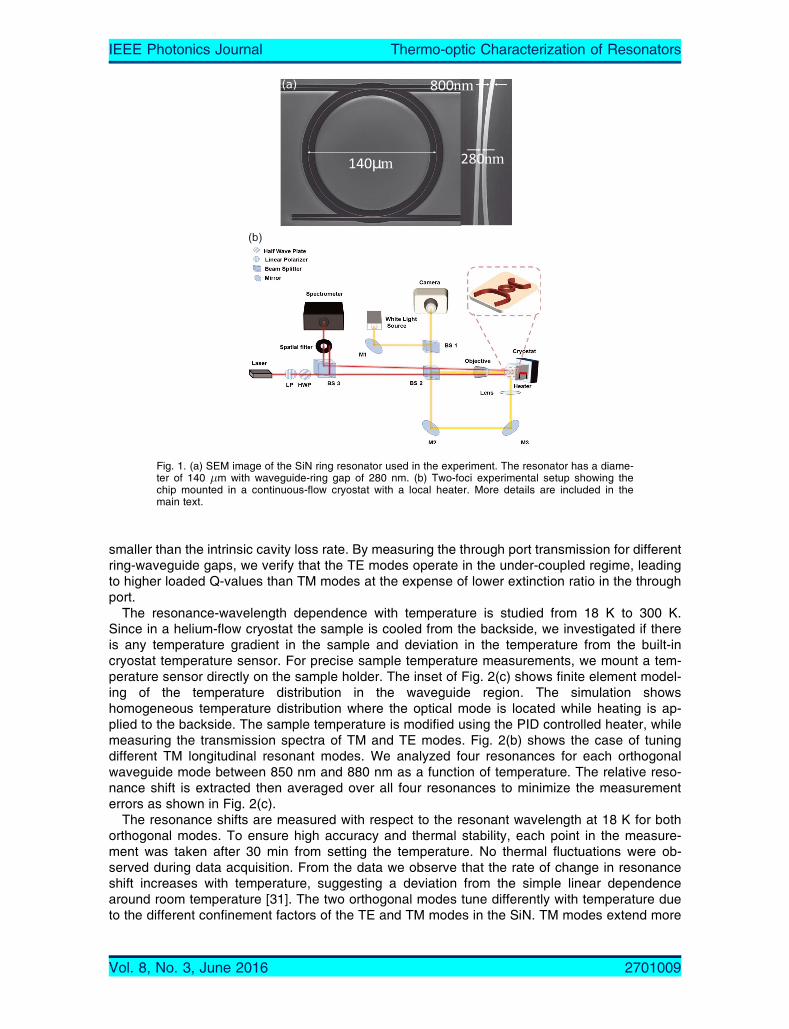
2. Experiment and ResultsWe characterize the thermo-optic coefficient of PECVD SiN and SiO2 based on studying theresonance tuning of traveling-wave mode cavities. The devices were fabricated using a 200 mmbare silicon wafer covered with 3 �m-thick thermal oxide serving as a low index barrier for totalinternal reflection in the SiN waveguide. Then, 200 nm of SiN was deposited using PECVD at300 °C, following a similar process reported previously [27] with no post-annealing to keep theprocess CMOS compatible and also to leave the possibilities open for integration with III-Vsources [28] and superconducting detectors. Waveguides and ring resonators are patternedusing 100 keV e-beam lithography on 950 K PMMA resist. After developing the resist, featureswere transferred to the SiN by complete etching of the SiN layer using CHF3/Ar based reactiveion etching. This was followed by a short O2 plasma cleaning step. Finally, the chip was claddedwith 2 �m PECVD SiO2 for symmetric mode confinement of both orthogonal modes in the wave-guide. The chip design employed a U-shape structure [29] with input and output waveguide sep-aration of 40 �m. This simplifies coupling to/from the side facet of the chip and separates inputand output beams spatially. Furthermore, the waveguides were terminated with an inverse taperfor efficient coupling and to allow only the fundamental mode to be excited [9], [30]. The taper isadiabatically increased to the main waveguide width of 800 nm. The resonator is designed tohave a diameter of 140 �m and gaps of 280 nm separating it from the waveguides. Fig. 1(a)shows a scanning electron microscope (SEM) image of the fabricated device. The chip is thencleaved at the inverse taper region along the wafer crystallographic direction to achieve a smoothfacet for enhanced coupling. The experimental setup is shown in Fig. 1(b). It consists of a contin-uous flow cryostat equipped with a PID controlled heater. The imaging system allows to indepen-dently view the top/side of the chip through removable beam splitter BS2 and mirror M2. Theside view helps to evaluate the laser spot profile while exciting the waveguide. For the excitation,we use a super continuum laser source equipped with an acoustic-optical tunable filter. We usea half-wave plate and a linear polarizer to control the input-state polarization coupled to thewaveguide. Finally, the output beam is directed to a 750 mm spectrometer with 1800 g/mm grat-ing terminated with a CCD. Fig. 2(a) shows the drop port transmission of TM and TE modes. Theloaded quality factors of TM and TE modes are 12,400 and 27,000, respectively. For the ring-waveguide gap of 280 nm, the coupling rate of the resonant TE modes to the waveguide is
Vol. 8, No. 3, June 2016 2701009
IEEE Photonics Journal Thermo-optic Characterization of Resonators
smaller than the intrinsic cavity loss rate. By measuring the through port transmission for differentring-waveguide gaps, we verify that the TE modes operate in the under-coupled regime, leadingto higher loaded Q-values than TM modes at the expense of lower extinction ratio in the throughport.
The resonance-wavelength dependence with temperature is studied from 18 K to 300 K.Since in a helium-flow cryostat the sample is cooled from the backside, we investigated if thereis any temperature gradient in the sample and deviation in the temperature from the built-incryostat temperature sensor. For precise sample temperature measurements, we mount a tem-perature sensor directly on the sample holder. The inset of Fig. 2(c) shows finite element model-ing of the temperature distribution in the waveguide region. The simulation showshomogeneous temperature distribution where the optical mode is located while heating is ap-plied to the backside. The sample temperature is modified using the PID controlled heater, whilemeasuring the transmission spectra of TM and TE modes. Fig. 2(b) shows the case of tuningdifferent TM longitudinal resonant modes. We analyzed four resonances for each orthogonalwaveguide mode between 850 nm and 880 nm as a function of temperature. The relative reso-nance shift is extracted then averaged over all four resonances to minimize the measurementerrors as shown in Fig. 2(c).
The resonance shifts are measured with respect to the resonant wavelength at 18 K for bothorthogonal modes. To ensure high accuracy and thermal stability, each point in the measure-ment was taken after 30 min from setting the temperature. No thermal fluctuations were ob-served during data acquisition. From the data we observe that the rate of change in resonanceshift increases with temperature, suggesting a deviation from the simple linear dependencearound room temperature [31]. The two orthogonal modes tune differently with temperature dueto the different confinement factors of the TE and TM modes in the SiN. TM modes extend more
Fig. 1. (a) SEM image of the SiN ring resonator used in the experiment. The resonator has a diame-ter of 140 �m with waveguide-ring gap of 280 nm. (b) Two-foci experimental setup showing thechip mounted in a continuous-flow cryostat with a local heater. More details are included in themain text.
Vol. 8, No. 3, June 2016 2701009
IEEE Photonics Journal Thermo-optic Characterization of Resonators
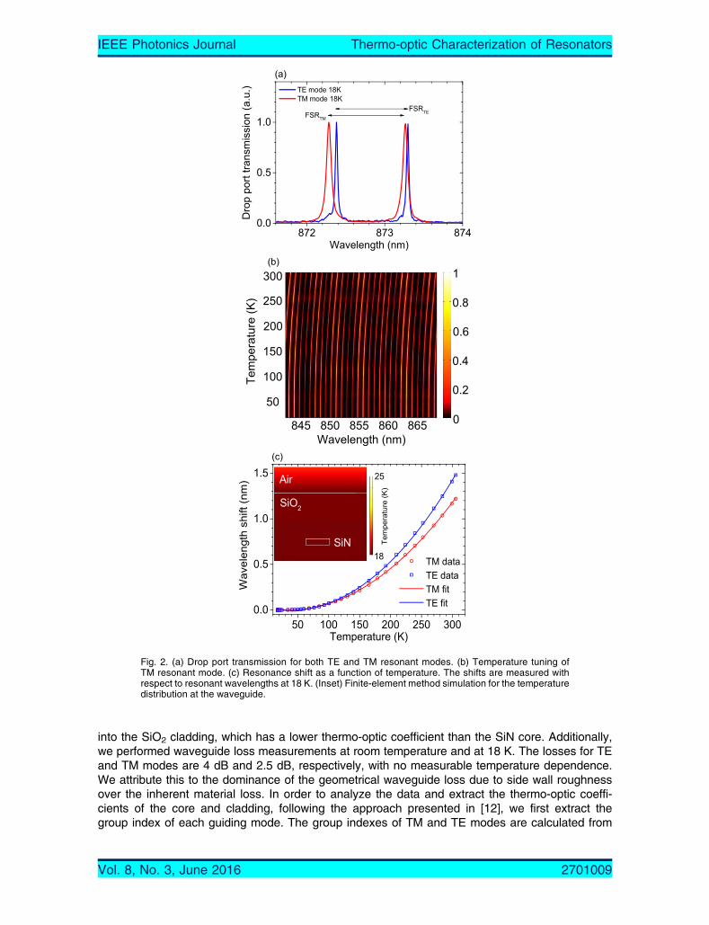
into the SiO2 cladding, which has a lower thermo-optic coefficient than the SiN core. Additionally,we performed waveguide loss measurements at room temperature and at 18 K. The losses for TEand TM modes are 4 dB and 2.5 dB, respectively, with no measurable temperature dependence.We attribute this to the dominance of the geometrical waveguide loss due to side wall roughnessover the inherent material loss. In order to analyze the data and extract the thermo-optic coeffi-cients of the core and cladding, following the approach presented in [12], we first extract thegroup index of each guiding mode. The group indexes of TM and TE modes are calculated from
Fig. 2. (a) Drop port transmission for both TE and TM resonant modes. (b) Temperature tuning ofTM resonant mode. (c) Resonance shift as a function of temperature. The shifts are measured withrespect to resonant wavelengths at 18 K. (Inset) Finite-element method simulation for the temperaturedistribution at the waveguide.
Vol. 8, No. 3, June 2016 2701009
IEEE Photonics Journal Thermo-optic Characterization of Resonators
the two measured free-spectral-ranges (FSR) and the length of the resonator [32]. For the TMresonance at 873.25 nm and the TE resonance at 873.3 nm, the measured FSRs are 0.98 nmand 0.92 nm, respectively. These correspond to mode which correspond to ng,TM = 1.767 andng,TE = 1.882. The thermo-optic coefficient of the core and the cladding materials are extractedby relating the thermally induced resonance shifts to individual material changes [12]:
d�TE
dT¼ @�TE
@ncore
@ncore@T
þ @�TE
@nclad
@nclad@T
(1)
d�TM
dT¼ @�TM
@ncore
@ncore@T
þ @�TM
@nclad
@nclad@T
: (2)
To solve these coupled equations for the cladding and core thermo-optic coefficient, we initiallycalculate the accompanying coefficients @�=@n.
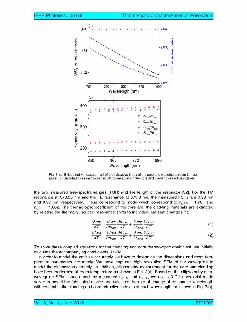
In order to model the cavities accurately we have to determine the dimensions and room tem-perature parameters accurately. We have captured high resolution SEM of the waveguide tomodel the dimensions correctly. In addition, ellipsometry measurement for the core and claddinghave been performed at room temperature as shown in Fig. 3(a). Based on the ellipsometry data,waveguide SEM images, and the measured ng,TM and ng,TE, we use a 3-D full-vectorial modesolver to model the fabricated device and calculate the rate of change of resonance wavelengthwith respect to the cladding and core refractive indexes at each wavelength, as shown in Fig. 3(b).
Fig. 3. (a) Ellipsometry measurement of the refractive index of the core and cladding at room temper-ature. (b) Calculated resonance sensitivity to variations in the core and cladding refractive indexes.
Vol. 8, No. 3, June 2016 2701009
IEEE Photonics Journal Thermo-optic Characterization of Resonators
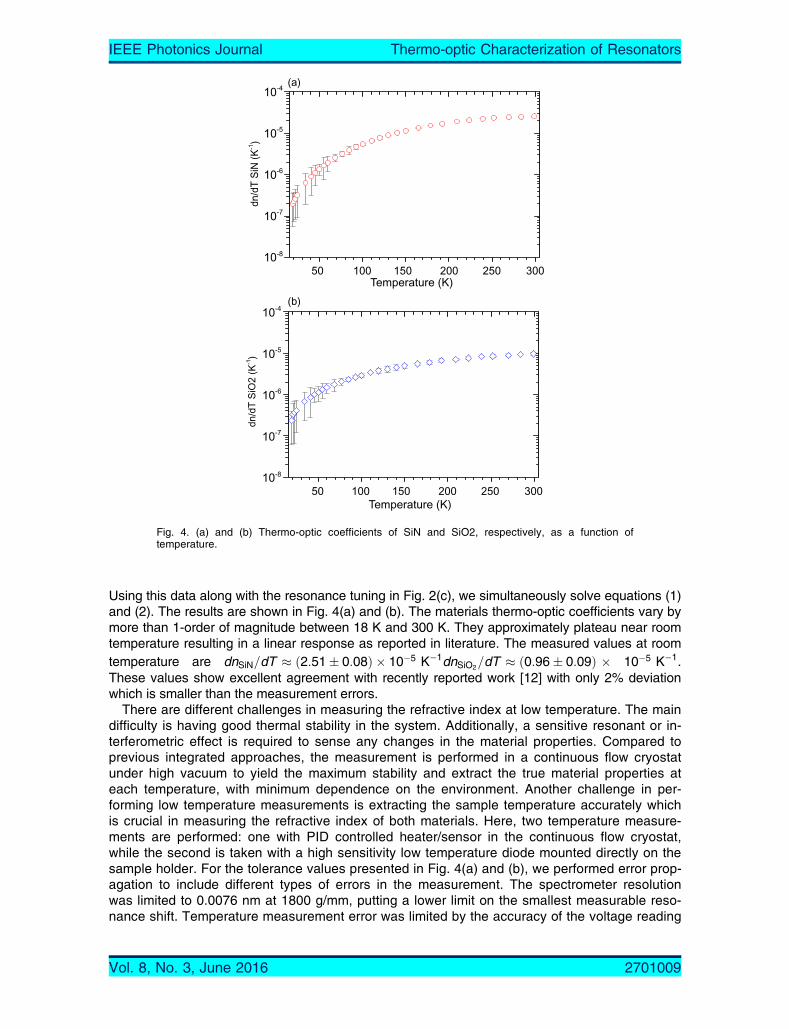
Using this data along with the resonance tuning in Fig. 2(c), we simultaneously solve equations (1)and (2). The results are shown in Fig. 4(a) and (b). The materials thermo-optic coefficients vary bymore than 1-order of magnitude between 18 K and 300 K. They approximately plateau near roomtemperature resulting in a linear response as reported in literature. The measured values at roomtemperature are dnSiN=dT � ð2:51� 0:08Þ � 10�5 K�1dnSiO2=dT � ð0:96� 0:09Þ � 10�5 K�1.These values show excellent agreement with recently reported work [12] with only 2% deviationwhich is smaller than the measurement errors.
There are different challenges in measuring the refractive index at low temperature. The maindifficulty is having good thermal stability in the system. Additionally, a sensitive resonant or in-terferometric effect is required to sense any changes in the material properties. Compared toprevious integrated approaches, the measurement is performed in a continuous flow cryostatunder high vacuum to yield the maximum stability and extract the true material properties ateach temperature, with minimum dependence on the environment. Another challenge in per-forming low temperature measurements is extracting the sample temperature accurately whichis crucial in measuring the refractive index of both materials. Here, two temperature measure-ments are performed: one with PID controlled heater/sensor in the continuous flow cryostat,while the second is taken with a high sensitivity low temperature diode mounted directly on thesample holder. For the tolerance values presented in Fig. 4(a) and (b), we performed error prop-agation to include different types of errors in the measurement. The spectrometer resolutionwas limited to 0.0076 nm at 1800 g/mm, putting a lower limit on the smallest measurable reso-nance shift. Temperature measurement error was limited by the accuracy of the voltage reading
Fig. 4. (a) and (b) Thermo-optic coefficients of SiN and SiO2, respectively, as a function oftemperature.
Vol. 8, No. 3, June 2016 2701009
IEEE Photonics Journal Thermo-optic Characterization of Resonators

on the diode and the corresponding temperature in its response function. Finally, the fitting erroris included and propagated through all the numerical operations, which is minimized by trackingmultiple resonances and averaging over them. By fitting the measured data, we extract thetemperature-dependent thermo-optic coefficients of SiN and SiO2 for the temperature rangeinvestigated.
dnSiNdT
ðT Þ ¼ 3:211� 10�7 � 1:990� 10�8 � T þ 8:856
� 10�10T 2 � 1:375� 10�12T 3 � 1:105� 10�15T 4 (3)
dnSiO2
dTðT Þ ¼ �1:167� 10�7 þ 1:727� 10�8 � T þ 1:861
� 10�10T 2 � 5:781� 10�13T 3 þ 4:221� 10�16T 4: (4)
Fig. 5 shows reported values in literature for the thermo-optic cofficient of silicon nitride atdifferent temperatures and measurement wavelengths. The presented work nicely complementsthe reported data for room temperature measurements and higher. On the otherhand, we seethat the sputtered SiN in [14] provides a slightly higher thermo-optic coefficient at visible andnear infra-red range, which may be attributed to different silicon content in the sample, gener-ally, the thermo-optic coefficient depends on the operating wavelength and the material compo-sition. For the presented measurements, we used a silicon nitride deposition process that issimilar to the work in [27].
To stress the importance of the presented results for low temperature performance of pho-tonic circuits, we fabricated local heaters on the ring resonators as shown in Fig. 6(a). Theheater consists of 80 nm thick titanium resistor separated by 3 micrometer of PECVD SiO2 fromthe ring. Although the small misalignment between the resonator and the heater decreases theefficiency of the tuning mechanism, we can compare the tuning power needed to achieve thesame wavelength shift for different temperature ranges using the same device. The resonanceshift of the TE mode as a function of the heater power is shown in Fig. 6(b). We clearly seelarger resonance tuning at room temperature compared to starting the tuning at 18 K due tothe larger thermo-optic coefficient. To reduce the required heat-budget, accurate heater-ringalignment in addition to innovative heater designs may be employed, such as the micro-ovenapproach [33].
3. ConclusionIn summary, we have measured the thermo-optic coefficients of SiN and SiO2 as a function oftemperature between 18 K and 300 K. The thermo-optic coefficients change by more than oneorder of magnitude over the whole temperature range. The SiN resonators have considerably
Fig. 5. Thermo-optic coefficient of silicon nitride reported in literature.
Vol. 8, No. 3, June 2016 2701009
IEEE Photonics Journal Thermo-optic Characterization of Resonators

high thermal stability at low temperatures at the expense of tunability. As an example, we stud-ied the performance of a fully integrated electro-optic filter at 18 K and at room temperature andshowed that the filter has considerably smaller tuning range at lower temperatures. As highertemperatures generally degrade the performance of quantum emitters and single photon detec-tors, the less efficient tuning sets a limit on the available thermal budget in such circuits. Thepresented results can be used as a reference for future designs of complex integrated photoniccryogenic circuits.
References[1] D. J. Moss, R. Morandotti, A. L. Gaeta, and M. Lipson, “New CMOS-compatible platforms based on silicon nitride
and Hydex for nonlinear optics,” Nat. Photon., vol. 7, pp. 1749–4885, 2013.[2] J. Riemensberger et al., “Dispersion engineering of thick high-Q silicon nitride ring-resonators via atomic layer de-
position,” Opt. Exp., vol. 20, no. 25, pp. 27661–27669, 2011.[3] M. A. Popovíc et al., “Multistage high-order microring-resonator add-drop filters,” Opt. Lett., vol. 31, pp. 2571–2573,
2006.[4] D. T. H. Tan, K. Ikeda, P. C. Sun, and Y. Fainman, “Group velocity dispersion and self phase modulation in silicon
nitride waveguides,” Appl. Phys. Lett., vol. 96, vol. 6, 2010, Art. no. 061101.[5] K. Ikeda, R. E. Saperstein, N. Alic, and Y. Fainman, “Thermal and Kerr nonlinear properties of plasma-deposited sili-
con nitride/silicon dioxide waveguides,” Appl. Phys. Lett., vol. 16, no. 17, pp. 12987–12994, 2008.[6] J. F. Bauters et al., “Ultra-low-loss high-aspect-ratio Si3N4 waveguides,” Opt. Exp., vol. 19, no. 4, pp. 3163–3174,
2011.[7] A. Griffith, J. Cardenas, C. B. Poitras, and M. Lipson, “High quality factor and high confinement silicon resonators
using etchless process,” Opt. Exp., vol. 20, pp. 21341–21345, 2012.
Fig. 6. (a) Microscope image of a top-heater integrated with a SiN ring-resonator. (b) Wavelengthshift as a function of the heater power at room temperature (red) and at 18 K (blue).
Vol. 8, No. 3, June 2016 2701009
IEEE Photonics Journal Thermo-optic Characterization of Resonators
[8] Q. Li et al., “Vertical integration of high-Q silicon nitride microresonators into silicon-on-insulator platform,” Opt.Exp., vol. 21, no. 15, pp. 18236–18248, 2013.
[9] A. Gondarenko, J. S. Levy, and M. Lipson, “High confinement micron-scale silicon nitride high Q ring resonator,”Opt. Exp., vol. 17, no. 14, pp. 11366–11370, 2009.
[10] J. S. Levy et al., “CMOS-compatible multiple-wavelength oscillator for on-chip optical interconnects,” Nat. Photon.,vol. 4, pp. 1749–4885, 2010.
[11] Y. Okawachi et al., “Octave-spanning frequency comb generation in a silicon nitride chip,” Opt. Lett., vol. 36, no. 17,pp. 3398–3400, 2011.
[12] A. Arbabi and L. L. Goddard, “Measurements of the refractive indices and thermo-optic coefficients of Si3N4 andSiOx using microring resonances,” Opt. Lett., vol. 38, no. 19, pp. 3878–3881, Oct. 2013.
[13] A. C. Hryciw, R. D. Kekatpure, S. Yerci, L. D. Negro, and M. L. Brongersma, “Thermo-optic tuning of erbium-dopedamorphous silicon nitride microdisk resonators,” Appl. Phys. Lett., vol. 98, no. 4, 2011, Art. no. 041102.
[14] A. R. Zanatta and I. B. Gallo, “The thermo optic coefficient of amorphous SiN films in the near-infrared and visibleregions and its experimental determination,” Appl. Phys. Exp., vol. 6, no. 4, 2013, Art. no. 042402.
[15] C. Schuck, W. H. P. Pernice, and H. X. Tang, “Waveguide integrated low noise NbTiN nanowire single-photon de-tectors with milli-Hz dark count rate,” Sci. Rep., vol. 3, 2013, Art. no. 1893.
[16] W. H. P. Pernice et al., “High-speed and high-efficiency travelling wave single-photon detectors embedded in nano-photonic circuits,” Nat. Commun., vol. 3, 2012, Art. no. 1325.
[17] S. L. Mouradian et al., “Efficient integration of high-purity diamond nanostructures into silicon nitride photonic circuits,”in Proc. CLEO, 2014, pp. 1–2.
[18] Y. Gong et al., “Linewidth narrowing and Purcell enhancement in photonic crystal cavities on an Er-doped siliconnitride platform,” Opt. Exp., vol. 18, no. 3, pp. 2601–2612, 2010.
[19] Y.-P. Huang, V. Velev, and P. Kumar, “Quantum frequency conversion in nonlinear microcavities,” Opt. Lett., vol. 38,no. 12, pp. 2119–2121, Jun. 2013.
[20] R. Wakabayashi et al., “Time-bin entangled photon pair generation from Si micro-ring resonator,” Opt. Exp., vol. 23,pp. 1103–1113, 2015.
[21] T. J. Kippenberg, R. Holzwarth, and S. A. Diddams, “Microresonator-based optical frequency combs,” Science,vol. 332, pp. 555–559, 2011.
[22] W. H. P. Pernice, C. Schuck, M. Li, and H. X. Tang, “Carrier and thermal dynamics of silicon photonic resonators atcryogenic temperatures,” Opt. Exp., vol. 19, pp. 3290–3296, 2011.
[23] M. K. Akhlaghi, E. Schelew, and J. F. Young, “Waveguide integrated superconducting single-photon detectors imple-mented as near-perfect absorbers of coherent radiation,” Nat. Commun., vol. 6, p. 9233, Sep. 2015.
[24] R. Amatya, C. W. Holzwarth, H. I. Smith, and R. J. Ram, “Precision tunable silicon compatible microring filters,”IEEE Photon. Technol. Lett., vol. 20, no. 20, pp. 1739–1741, Oct. 2008.
[25] S. Yokoyama, F. Qiu, Y. Feng, A. M. Spring, and K. Yamamoto, “0.018 pm/°C athermal silicon nitride ring resonatorby polymer cladding,” in Proc. CLEO-PR, 2013, pp. 1–2.
[26] B. Guha, J. Cardenas, and M. Lipson, “Athermal silicon microring resonators with titanium oxide cladding,” Opt.Exp., vol. 21, no. 22, pp. 26557–26563, 2013.
[27] A. Gorin, A. Jaouad, E. Grondin, V. Aimez, and P. Charette, “Fabrication of silicon nitride waveguides for visible-lightusing PECVD: A study of the effect of plasma frequency on optical properties,” Opt. Exp., vol. 16, no. 18,pp. 13509–13516, 2008.
[28] I. Esmaeilzadeh et al., “Deterministic integration of single photon sources in silicon based photonic circuits,” NanoLett., vol. 16, pp. 2289–2294, 2016.
[29] Y. Xia, C. Qiu, X. Zhang, W. Gao, J. Shu, and Q. Xu, “Suspended Si ring resonator for mid-IR application,” Opt.Lett., vol. 38, no. 7, pp. 1122–1124, 2013.
[30] A. C. Turner et al., “Tailored anomalous group-velocity dispersion in silicon channel waveguides,” Opt. Exp., vol. 14,pp. 4357–4362, 2006.
[31] N. Ter-Gabrielyan, V. Fromzel, and M. Dubinskii, “Linear thermal expansion and thermo-optic coefficients of YVO4crystals the 80–320 K temperature range,” Opt. Exp., vol. 2, pp. 1624–1631, 2012.
[32] P. Rabiei, W. H. Steier, C. Zhang, and L. R. Dalton, “Polymer micro-ring filters and modulators,” J. Lightw. Technol.,vol. 20, no. 11, pp. 1968–1975, Nov. 2002.
[33] L. Cao, A. A. Aboketaf, and S. F. Preble, “CMOS compatible micro-oven heater for efficient thermal control of siliconphotonic devices,” Opt. Commun., vol. 305, pp. 66–70, Sep. 2013.
Vol. 8, No. 3, June 2016 2701009
IEEE Photonics Journal Thermo-optic Characterization of Resonators