Thermo Forming
81
Technical Manual THERMOFORMING
description
Technical ManualTHERMOFORMING
Transcript of Thermo Forming

Technical ManualTHERMOFORMING
2 Thermoforming
INDEX
Thermoforming principles-History of thermoforming industry-Products manufactured by thermoforming
Suitable polymers for thermoforming -Thermal properties-Temperature-Heat measurement-Specific heat-Thermal conductivity
Heating plastics-Heat transfer: conductivity, convection and radiation
-Thermal properties of plastics-Heat transmission media-Temperatures and forming cycles-Establishing the right temperaturefor the material
Thermoforming equipments-Gas furnaces with pressured air circulation-Infrared heating furnace-Lineal heating electric resistors
Complementary equipment: vacuum, pressured airand mechanical forces
-Vacuum forming-Pressured air forming-Mechanical forming-Combined techniques-Mechanical support design
Thermoforming molds-Choosing thermoforming technique-Criteria to design thermoformed products-Criteria to design thermoforming molds-Considerations in designing thermoforming molds
-Materials used to manufacture tthermoform - ing molds
4
7
11
17
25
31
3 Thermoforming
Thermoforming techniques-Bi-dimensional thermoforming-Tri-dimensional thermoforming (with molds)-Molding techniques in infrared heatingfurnace
Cooling thermoformed products-Conventional cooling methods-Non-conventional cooling methods
Cutting thermoformed products-Cutting equipment-Cutting techniques
Thermoforming variables-Material variables-Mold variables-Pre-stretching variables-Mechanical support variables
Problem and solution guide
Appendix-Glossary-Glass fiber reinforced plastic-Unit conversion table
46
51
53
58
62
68

4 Thermoforming
Thermoforming principles
Since the beginning of the XX century some techniques to form sheets, with materialssuch as metal, glass and natural fibers, have been known. The true thermoformingprinciples emerged as thermoplastic materials were developed, which happened dur-ing the second world war. The post-war period brought about mass commercializationand rapid development of equipment and machinery capable to adapt to the manu-facturing modern methods, to make more useful and income yielding products.
In the 50s, the volume of thermoplastic material production and the products madewith it reached impressive figures. In the 60s, by developing the thermoforming indus-try, the foundations for the future were established. Then huge consumers and prod-uct competitiveness, in the 70s, required high speed productive machinery. Equipmentmanufacturers met those needs by making machinery capable to produce about onehundred thousand thermoformed individual containers per hour. Sophisticated controlswere also required.
Since the 80s up to the present, thermoformers have so much relied on their processthat they have gone beyond their expectations and have established production linesthat can produce finished thermoformed products, not only from sheets but also fromresin pellets; besides, they recycle the scrap with minimum control. Equipments havebeen computerized and at present, they can perform auto-monitoring and diagnosticfunctions. Nowadays, very complex equipment does not require more than one work-er to handle and control it thanks to electronic advances. Thus, it is believed that thethermoforming industrial labor market will undergo a shortage of technically trainedand experienced personnel, since traditional knowledge will no longer be enough.Therefore, lectures, seminars, courses, etc., would be useful to increase thermoform-ers´ general knowledge, and would further advance this well established industry.
Many of the thermoformed products in use at present have been manufactured toreplace their original use forms. This has taken place so fast that those original oneshave been almost forgotten. For example: it is not easy to remember in what ham-burgers were packed before the arrival of the one piece polystyrene package or whatkind of material lined the interior of refrigerators.
The following list begins with the area with the most number of thermoformed piecesand continues in a decreasing order up to the one with the fewer pieces.
Packaging industrySince the beginning of the thermoforming process, the packaging industry has beenthe most benefited due to the high productivity and benefits (cost-profit) that it offers.
History of thermoforming
industry
Manufacturingthermoformed
products

5 Thermoforming
At present, most of the packaging equipments (blister) are high speed automaticallysustained. These equipments are called "form-fill-seal" and are used to pack cosmet-ics, cold cuts, sodas, candies, stationery, etc.
Take away food industryIn the growing "take away food" industry, a great deal of thermoformed products areused, ranging from a complete meal container (divided containers), to hamburgers andsandwich packages, sodas, etc.
Usually, that industry requires printed thermoformed packages. This printing can bemade before or after thermoforming. Some examples of this are trays, cups, sandwich,hamburger, hot-dog packages, etc.
Food packaging industrySupermarkets are the great consumers of thermoformed containers. The materialsused are low-cost thermoplastics. These are designed to be piled or placed in differ-ent forms. Examples: meat, fruit, eggs and vegetables containers.
TransportPublic and private transport such as bus, train subway, plane, car, etc., has within itsequipment many thermoformed plastic parts. Most of these are used for inside finish-ing or non-structural exterior parts. In others, they are used for seats, backs and armsof seats, fronts of doors, service tables, wind-shields, instrument protectors, guards,spoilers, etc.
Signaling and advertisementsThese are usually made of acrylic and can consist of only one piece and can be verylarge. Transparent (clear) acrylic is generally used and it is painted on the inside usingacrylic based paint.
The use of acrylics for exteriors makes advertisements weather resistant and they vir-tually need no maintenance; furthermore, they can stand extreme cold or hot weatherconditions. Exterior lighted bill-boards, interior advertisements, signaling in publicplaces, offices, etc., are some examples.
Household productsThere is a great deal of products that have thermoformed parts; actually, they are pro-duced in great quantities. They can be found in cabinet, washing machines, dishwashers, dryers, refrigerators, air conditioning outlets, humidifiers, T.V. and radio cab-inets, etc.
Food industryOne of the oldest and greatest thermoformed product consumers is the food industry.The use of trays and other accessories has a greater potential use, besides the great

6 Thermoforming
users like hospitals, nurseries, schools fairs and others, there are the military sectorand international aid organizations. Some examples of products are: trays, cups andplates.
Medical industryThe medical industry requires a great variety of products and sterilized packaging forhospitals, clinics and doctors´ offices. The specifications for these products are usual-ly very strict and recycling materials is unacceptable.
The use of acrylic , since it is physiologically harmless, is growing every day. Someexamples are: chirurgical equipment, syringes and needles, chirurgical tables, cabi-nets, incubators, dentists´ seats and exercise platforms.
Agriculture and horticultureCommercialization of decoration plants in supermarkets and specialized shops hasgenerated, for some time, the need to make flower pots and small containers, includ-ing with multiple divisions for exhibiting and selling. This kind of containers are madeof recycled plastic at low cost. Flower pots, different size and divided containers, smallgreen houses, trays for growing seeds, planting containers, etc., are some examples.
Constructión and housingFor some years, construction industry has used thermoformed products, which havebecome quickly popular. Thermoformed parts have easily replaced a lot of products.Actually, there are products that cannot be manufactured any other way, such as sky-lights or cannon arches. In this sector, acrylic is used a lot because of its weatherresistant properties and its thermoforming quality.
Examples of these are: skylights, cannon arches, hydro-massage tubs, bath modules,wash basins, bathroom screens and cabinets, tables, chairs, lamp stands, kitchenitems, stairs, frontages, partings, windows, aquariums, etc.
LuggageSome luggage manufacturers are deciding in favor of using the thermoformingprocess, since it has advantages over the injection products. Because it is moldedeffortlessly, the possibility of thermoformed products fracturing is reduced. Examples:all kinds of suitcases, briefcases, etc.
Photography equipmentOne of the oldest thermoformed products is the tray used for developing photos, alsoflash bulbs (metallic reflector) and the magazine for standing cameras, even though itsmanufacturing requires a precision thermoforming technique.

7 Thermoforming
Suitable polymers for thermoforming
Basically, every thermoplastic polymer is suitable for the thermoforming process.Those materials, when exposed to heating, show an elasticity, hardness, and resist-ance capacity, under load variation in their module. With an increased temperature overthe H.D.T., the material will tend to become rubber-like, having as critical value thetemperature of annealing of the thermoplastic polymer. This can be seen in the rapidbending of the hot sheet, when the force of gravity is strong enough to cause thisdeformity.
Table 1 shows the suitable and most common polymers for thermoforming, as well astheir temperature.
POLYMERS
HEATING DEFLECTION TEMPERATURE
AT 264 PSI(ºF)
AT 66PSI(ºF)
WITHOUTCHARGE
(ºF)
SHEETTEMP.
(ºF)
MOLDTEMP.
(ºF)
AID TEMP(ºF)
THERMOFORMINGTEMPERATURE
Extruded acrylicCell-cast acrylicCellulose acetobutyrateHigh density polyethylenePolypropylenePolystyreneHigh impact polystyreneSANABSPolyvinyl chloride (RV.C.)Polycarbonate
201.2 204.8
149-167
131-149158-203185-203
212 167-239
158 266
208.4230
167-176140-176230-239158-212194-203
221 176-248
167 248
248-302212 284 212 248
203 230 320
275-347320-356284-320293-374293-392284-338338-356428-446248-356275-347356-446
149-167149-167
203
113-149 113-149
158-185 113
203-248
338
194194
194 176 284
One of the least considered aspects in thermoforming practice, is that of the ther-mal properties of polymers which is one of the most relevant and critical aspects ofthe process. Wholly understanding these factors will reduce the risk of long pre-pro-duction run or bad adjusting of the product to the outline.
When we talk about thermal properties, it is indispensable to establish the conceptsrelated to this topic. First, it must be remembered that energy often dissipatesthrough friction and then it appears as heat or the inner thermal energy of a body.Of course, some times, heat in a substance is increased deliberately to change itstemperature or its form.
Thermalproperties
8 Thermoforming
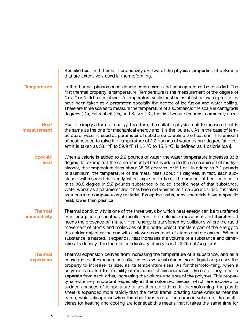
Specific heat and thermal conductivity are two of the physical properties of polymersthat are extensively used in thermoforming.
In the thermal phenomenon debate some terms and concepts must be included. Thefirst thermal property is temperature. Temperature is the measurement of the degree of"heat" or "cold" in an object. A temperature scale must be established, water propertieshave been taken as a parameter, specially the degree of ice fusion and water boiling.There are three scales to measure the temperature of a substance: the scale in centigradedegrees (°C), Fahrenheit (°F), and Kelvin (°K), the first two are the most commonly used.
Heat is simply a form of energy, therefore, the suitable physics unit to measure heat isthe same as the one for mechanical energy and it is the joule (J). As in the case of tem-perature, water is used as parameter of substance to define the heat unit. The amountof heat needed to raise the temperature of 2.2 pounds of water by one degree [at pres-ent it is taken as 58.1ºF to 59.9 ºF (14.5 °C to 15.5 °C) is defined as 1 calorie (cal)].
When a calorie is added to 2.2 pounds of water, the water temperature increases 33.8degree, for example: if the same amount of heat is added to the same amount of methyl-alcohol, the temperature rises about 35.06 degrees, or if 1 cal. is added to 2.2 poundsof aluminum, the temperature of the metal rises about 41 degrees. In fact, each sub-stance will respond differently when exposed to heat. The amount of heat needed toraise 33.8 degree in 2.2 pounds substance is called specific heat of that substance.Water works as a parameter and it has been determined as 1 cal./pounds, and it is takenas a basis to compare every material. Excepting water, most materials have a specificheat, lower than plastics.
Thermal conductivity is one of the three ways by which heat energy can be transferredfrom one place to another; it results from the molecular movement and therefore, itneeds the presence of matter. Heat energy is transferred by collisions where the rapidmovement of atoms and molecules of the hotter object transfers part of the energy tothe colder object or the one with a slower movement of atoms and molecules. When asubstance is heated, it expands, heat increases the volume of a substance and dimin-ishes its density. The thermal conductivity of acrylic is 0.0005 cal./seg. cm2
Thermal expansion derives from increasing the temperature of a substance, and as aconsequence it expands, actually, almost every substance: solid, liquid or gas has theproperty to increase its size, as its temperature rises. As for thermoforming, when apolymer is heated the mobility of molecular chains increases, therefore, they tend toseparate from each other, increasing the volume and area of the polymer. This proper-ty is extremely important especially in thermoformed pieces, which are exposed tosudden changes of temperature or weather conditions. In thermoforming, the plasticsheet is expanded more rapidly than the metal frame, creating some wrinkles near theframe, which disappear when the sheet contracts. The numeric values of the coeffi-cients for heating and cooling are identical; this means that it takes the same time for
Temperature
Heat measurement
Specific heat
Thermalconductivity
Thermal expansion

9 Thermoforming
a piece to get hot as to get cool. It must be taken into consideration that there mightbe problems when the thermoformed parts have to be within a very close dimensionaltolerance. There might be other kinds of problems when there is shrinkage in a malemold, making it difficult to remove the part from the mold. The thermal expansion coef-ficient of acrylic is 0.00009 cm./cm./°C.
10 Thermoforming
Heating plastics
In the thermoforming process, the heating operation is one of the longest stages inwhich there might be present the most difficulties and material and human resourceswaste. That is why this chapter is devoted to heat transfer, aiming at trying to clarifyphenomena that might occur in plastics heating operation.
Although scientists have divided heat transfer into three different phenomena: con-duction, convection and radiation, in practice, the three phenomena are concurrent.
ConductionThis is heat transfer from one part of a body to another part of the same body, or fromone body to another which is in physical contact with it, without a substantial dis-placement of the particles of the body.
ConvectionThis is heat transfer from one point to another, in a fluid, gas or liquid (by mixing onepart of the fluid with another). In natural convection, the movement of the fluid totallyderives from the difference in density as a result of different temperatures. In the forcedconvection, which is the one we are interested in, the movement is produced bymechanical means. When velocity is relatively low, it must be noted that free convec-tion factors, such as different temperature and density, may have an important influence.
RadiationThis is heat transfer from one body to another that is not in contact with it, by meansof a wavy movement through space.
For the purposes of thermoforming process, three media for heat transfer are considered:
A) Contact with a solid, liquid or hot gas.B) Infrared radiation.C) Internal excitation or by microwaves.
The first two ones are very much used in plastic thermoforming and for several of themthe scope of temperature is between 120°C and 205°C (250°F and 400°F).
Heat transfer:conduction,convection
and radiation

11 Thermoforming
Plastics are poor heat conductors; therefore, thick sheets need a considerably longtime to heat. In table 8, there are some thermal properties of some materials to be com-pared. In plastic thermoforming the method and size of the heating equipment must betaken into consideration.
Heating a sheet on both sides (sandwich-like heating) helps to reduce the time takenin this operation. In some cases, heating time can be reduced if the sheet is pre-heat-ed and kept at a medium temperature; however, this is rarely done with less than 6mm.thick materials.
In addition, the amount of heat required to raise the temperature of plastics is high,compared with any other material; except water. To estimate the needed heat for asheet, the following formula can be used.
Required heat = Length X width X thickness X density of material X (specific heat X dif-ferent temperature + fusion heat)
Thermalpropertiesof plastics
MATERIALSSPECIFICGRAVITY
g/cm3
SPECIFICHEAT
Btu/ Ib 0F
FUSIONHEAT Btu/lb
THERMAL CONDUCTIVITY Btu ft/sq ft hr 0F
THERMALCOEFFICIENT
of LINEAL in/in 0F10-5
AirWaterIceSoft woodHard woodPhenol R.Epoxy R. PolyethyleneAcrylicPolycarbonateGraphiteGlassQuartzAluminumSteelCopper
0.0012 1
0.92 0.5 0.7 1.5
1.6-2.1 0.96 1.19 1.2 1.5 2.5 2.8 2.7 7.8 8.8
144 144
55
171 171 88
0.24 1
0.5 0.4 0.4 0.3 0.3
0.37 0.35 0.30 0.20 0.20 0.20 0.23 0.10
0.092
0.014 0.343 1.26
0.052 0.094 0.2
0.1-0.8 0.28
0.108 0.112
87 0.59 4 y 8 90 27
227
2.8 1.5 1.5 3-5
1.5-2.8 7
3.5 3.7
0.44 0.5
0.4 y 0.7 1.35 0.84 0.92
Table 8: Thermal properties of some materials.
12 Thermoforming
Heattransfer
media
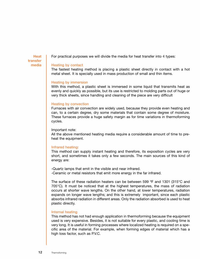
For practical purposes we will divide the media for heat transfer into 4 types:
Heating by contactThe fastest heating method is placing a plastic sheet directly in contact with a hotmetal sheet. It is specially used in mass production of small and thin items.
Heating by immersionWith this method, a plastic sheet is immersed in some liquid that transmits heat asevenly and quickly as possible, but its use is restricted to molding parts out of huge orvery thick sheets, since handling and cleaning of the piece are very difficult
Heating by convectionFurnaces with air convection are widely used, because they provide even heating andcan, to a certain degree, dry some materials that contain some degree of moisture.These furnaces provide a huge safety margin as for time variations in thermoformingcycles.
Important note:All the above mentioned heating media require a considerable amount of time to pre-heat the equipment.
Infrared heating:This method can supply instant heating and therefore, its exposition cycles are veryshort, and sometimes it takes only a few seconds. The main sources of this kind ofenergy are:
-Quartz lamps that emit in the visible and near infrared.-Ceramic or metal resistors that emit more energy in the far infrared.
The surface of these radiation heaters can be between 599 ºF and 1301 (315°C and705°C). It must be noticed that at the highest temperatures, the mass of radiationoccurs at shorter wave lengths. On the other hand, at lower temperatures, radiationexpands on longer wave lengths; and this is extremely important, since each plasticabsorbs infrared radiation in different areas. Only the radiation absorbed is used to heatplastic directly.
Internal heatingThis method has not had enough application in thermoforming because the equipmentused is very expensive. Besides, it is not suitable for every plastic, and cooling time isvery long. It is useful in forming processes where localized heating is required on a spe-cific area of the material. For example, when forming edges of material which has ahigh loss factor, such as P.V.C.
13 Thermoforming
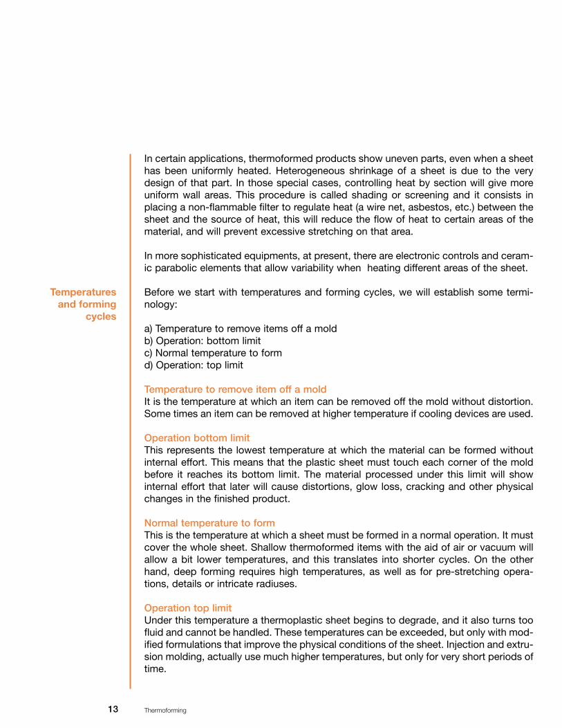
In certain applications, thermoformed products show uneven parts, even when a sheethas been uniformly heated. Heterogeneous shrinkage of a sheet is due to the verydesign of that part. In those special cases, controlling heat by section will give moreuniform wall areas. This procedure is called shading or screening and it consists inplacing a non-flammable filter to regulate heat (a wire net, asbestos, etc.) between thesheet and the source of heat, this will reduce the flow of heat to certain areas of thematerial, and will prevent excessive stretching on that area.
In more sophisticated equipments, at present, there are electronic controls and ceram-ic parabolic elements that allow variability when heating different areas of the sheet.
Before we start with temperatures and forming cycles, we will establish some termi-nology:
a) Temperature to remove items off a moldb) Operation: bottom limitc) Normal temperature to formd) Operation: top limit
Temperature to remove item off a moldIt is the temperature at which an item can be removed off the mold without distortion.Some times an item can be removed at higher temperature if cooling devices are used.
Operation bottom limitThis represents the lowest temperature at which the material can be formed withoutinternal effort. This means that the plastic sheet must touch each corner of the moldbefore it reaches its bottom limit. The material processed under this limit will showinternal effort that later will cause distortions, glow loss, cracking and other physicalchanges in the finished product.
Normal temperature to formThis is the temperature at which a sheet must be formed in a normal operation. It mustcover the whole sheet. Shallow thermoformed items with the aid of air or vacuum willallow a bit lower temperatures, and this translates into shorter cycles. On the otherhand, deep forming requires high temperatures, as well as for pre-stretching opera-tions, details or intricate radiuses.
Operation top limitUnder this temperature a thermoplastic sheet begins to degrade, and it also turns toofluid and cannot be handled. These temperatures can be exceeded, but only with mod-ified formulations that improve the physical conditions of the sheet. Injection and extru-sion molding, actually use much higher temperatures, but only for very short periods oftime.
Temperaturesand forming
cycles
14 Thermoforming
General recommendationsa) The characteristics of a finished product are determined by the kind of thermoform-
ing technique used.b) The material must be heated evenly at the annealing and forming point, before it
cools below its molding temperature. c) Acrylic must cool slowly and evenly while it is in the mold. d) The formed piece must be cool before any finishing is done, like spraying paint or
serigraphy. e) In the design of a piece, a 2% shrinkage in both directions and a 4% increase in
thickness must be taken into consideration, as well as a 0.6% contraction at 1% when cooling
Temperatures and forming cyclesAs it was previously mentioned, one of the most important steps of the thermoformingprocess is determining the right temperature of the material. For acrylic, the right selec-tion of annealing or normal temperature will prevent:
At a low temperature:Internal effort concentrates in the thermoformed piece which later, under sudden envi-ronmental temperature changes, will emerge as fissures or cracking.
At high temperature:Bubbles and mold marks, due to extreme heating.
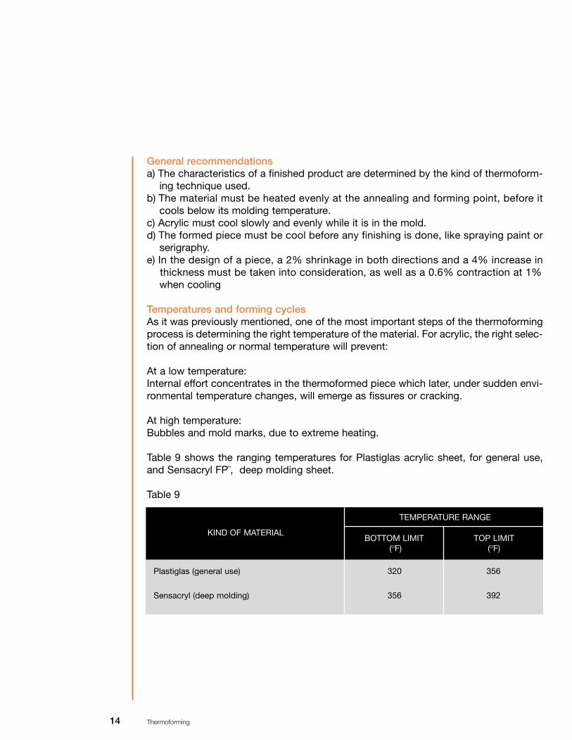
Table 9 shows the ranging temperatures for Plastiglas acrylic sheet, for general use,and Sensacryl FP¨, deep molding sheet.
Table 9
KIND OF MATERIALBOTTOM LIMIT
(OF)TOP LIMIT
(OF)
TEMPERATURE RANGE
Plastiglas (general use)
Sensacryl (deep molding)
320
356
356
392

15 Thermoforming
In Mexico, due to the high cost of electricity, it is more common to use a convectionfurnace with pressured air re-circulation by means of gas, for which a very practical for-mula is very useful to determine the permanence time for an acrylic sheet, taking intoconsideration the annealing temperature range previously adjusted.
Formula: 53.3 X E (inches) = T (min.)Where : 53.3 = Factor, E = Thickness of material, T = time.
This formula can be used for thin (0.04 to 0.24 inches) Chemcast sheets. For thickersheets, the factor has to be changed as follows:
Formula: 3 X E (inches) = T (min). Ex: 53.3 X 0.118 = 6.30 min.
As it has already been mentioned, there are variables that may modify these formulas,such as: environmental temperature of the place where the furnace is located, cure(especially in extreme weather conditions), material thickness fluctuation and the con-ditions of the equipment among other things.
Forming temperatureEvery thermoplastic material has a process specific temperature. These ranges applywithout taking into consideration the way the material will be processed. The mostused materials compared with acrylic are mentioned in table 10:
Table 10, Ranges of forming temperature
MATERIALSHEETTEMP.
(0F )
BOTTOMLIMIT (0F )
TOPLIMIT
(0F )
MOLDTEMP. (0F )
MECHANICALSUPPORT
TEMP. (°F)
REMOVALTEMP. (0F )
NORMAL(0F )
Acrylic CHEMCAST Sensacryl FPABS PolycarbonateAD Polyethylene
320- 356356-392257-356392-482320-428
320 356257 392320
338374329455374
356392356482428
210248338
248266185284185
149-167158-176158-185194-248194-212
Another important factor in the thermoforming process, is establishing the right tem-perature for plastic material. You must bear in mind that apart from the heat trans-mission medium, a sheet must be heated at the recommended range of temperature(annealing range), besides, a sheet has to be heated in an evenly way.
In practice, it is not easy to accurately establish the temperature of the sheet, evenwhen using contact thermometers; therefore, this determination is based on the per-formance of a sheet. The gradual change in which a sheet yields during the heating
EstablishIngthe right
temperature of the material

16 Thermoforming
process (annealing point), is one of the cues to establish the right temperature. Somecontrols for infrared radiation thermoforming equipment have been developed, wherea sheet is fastened horizontally, and the "yielding" or "bending" phenomenon is used,and photo-electric cells control heating time and/or temperature.
Clamp
FrameVacuum box
Photo-electric cellsSolenoid valve controlled byphotoelectric cells.
However, this criterion cannot be applied indiscriminately to every plastic, since somematerials may over-heat before they begin to yield or bend. Although a range of tem-perature is established, the expected temperature of a sheet may not be achieved; thismay be caused by:a) Fluctuations in the thickness of the materialb) Temperature changes in the equipment and/or environmentc) Minimum fluctuations in the line voltage (in infrared equipment).d) The regulator of the pressured air circulation gas equipment may not be the right
one, there is not enough gas pressure, the burner is not the right one or it may beblocked with soot, etc.
There are cone formed pyrometers, infrared radiation or gas (hot air) heating tablets,that can render a more accurate measurement. Although probably, the best way tomeasure the temperature of a sheet is by means of an infrared pistol, which measuresby zones; though the equipment is expensive, it is the only one that measures the tem-perature of a sheet accurately and reliably.
17 Thermoforming
Thermoforming equipments
Originally, convection furnaces were the first equipments to heat plastic sheets thatwere going to be thermoformed, and up to now, that kind of heating is still preferredfor sheets of different thickness, and for temperature even distribution.
Heat can be applied with gas or electric resistor units. To produce air circulation from4,500 to 6,100 cm3/min. (150 to 200 feet3/min), pressured air re-circulation and deflec-tors are crucial to get homogeneous temperatures. The furnace temperature must beadjusted to the plastic forming temperature.
Infrared radiation heating, compared with oil immersion or contact heating (the two lat-ter very limited in practice), is extremely rapid. For example, a 3.0 mm sheet heatingtime by infrared radiation can be achieved in one min. at about 10 watts/inch2.
Because infrared radiation heating takes very little time, heat energy absorbed by asheet may cause over-heating, that may even affect the degrading of the material(bubbles or burning) if it is not controlled. It is important to consider that in long runs,the furnace temperature has to be gradually reduced.
In some cases, when the product has intricate or very deep sections, there is the riskof the thickness of the material considerably thinning; in this case screens must beused (they may be made of perforated plate or metallic display) to prevent over-heat-ing.
The elements of infrared radiation can be obtained in a very wide range of designs,according to their importance they are:
1.- Tungsten filaments in quartz tubes or lamps, temperature 3992 ºF (2,200 °C).2.- Spring- like nichrome resistor on refractory ceramic bases.3.- Nichrome resistors protected by plate or stainless steel tubes.
There are manufacturers who make infrared radiation thermoforming machines in awide variety of sizes, capacity, degree of automation and versatility.
The specifications to acquire a thermoforming machine vary depending on the finishedproduct that you want to get and therefore, it is necessary to consider:
Voltage, wattage, amperage, useful area of forming, number of heaters (lower andupper), controls to regulate temperatures by zones, degree of automation, capacity to

18 Thermoforming
Gas furnaceswith pressured
air circulation
accept mechanical support, type of sheet fastening device, (clamps, mechanical,pneumatic, etc.), ventilators to cool the product, general dimensions, productioncapacity, cost- profit.
This kind of furnace supplies uniform heat and constant temperature, with a minimumrisk of over-heating an acrylic sheet. Electric ventilators must be used to force hot aircirculation on the acrylic sheet at a speed about 4,500 to 6,100 cm3/min., anddevices to distribute the air in every zone of the furnace.
Gas furnaces need heat inter-changers to prevent accumulation of soot due to thegas flow, as well as controls to interrupt the gas flow, when necessary.
Electric furnaces can be heated, using sets of 1000 watts resistors. When using a fur-nace with a 10 m3 capacity, about 25,000 power watts will be consumed and half ofthis will be used to compensate heat loss due to leakage, insulating transmission andthe use of doors. A minimum 2" thick insulation is advised and the doors of the fur-nace should be as narrow as possible, to reduce most of the temperature loss.
Automatic devices must be used to strictly control temperature between 32 ºF and482 ºF (0 °C and 250 °C). To get a more uniform sheet heating, it is important to hangit vertically, and this can be done with a system that fastens the material all along withclamps or canals with springs which move on wheels that slide on rails, like the onesused for closets.
Basic criteria to construct a gas furnace with pressured air circulation.The best advice in this case, is asking any industrial furnace manufacturer to buildone with the mentioned characteristics, since the construction of one, specially theheating and operation systems, is very risky for anybody who has only little knowl-edge on the subject.
This kind of equipment must be approved by specialists in gas installations, it alsohas to be registered before the corresponding authorities.
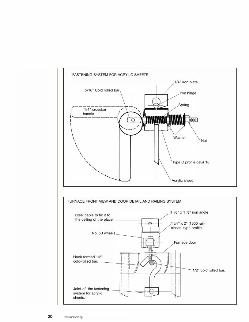
It is also relevant to point out that the information provided here, is only related to themetallic structure and fastening system for acrylic sheets. A furnace construction canbe divided into the following sub-systems:
A) StructureB) Fastening acrylic sheetC) Electric systemD) Gas installation E) Controls

19 Thermoforming
Recommendations to build a furnaceBuilding the structure with commercial iron tubular of 11/2" X 11/2" or 2 X 2".
a) Cut it according to the measurements and requirements of design.b) Weld the lateral walls.c) Weld the upper wall, the lower one and the back one; to join them with the lateral ones,
and build the whole structure.d) Line the inner part of the structure with a black plate cal. 18 and weld it or rivet it with
"pop".e) Cover the holes (thickness of the tubular) with a rigid sheet of glass fiber to get ther-
mal insulation, code RF-4100, or a similar one.f) Line the exterior with a black plate cal. 18 and rivet it with "pop" or weld it.g) Make the doors with a structure of tubular PTR 1" X 1", and follow the same instruc-
tions as for the walls, they should be shorter to leave room for the rails.h) Attach the doors to the furnace with hinges.i) Put the closet-type rails, they should be twice as long as the furnace. They are fixed
with screws on the upper part of the furnace. Once they are fixed to the furnace andthe furnace on its place where it will operate, using bearings fasten the rails to the ceil-ing or structure of the place.
GAS STRUCTURE WITH AIR RE-CIRCULATION
Closet-type rails
Plate "U" bearings of 1/4”
The electric ventilator isplaced in this section toforce the air
Every joint must be weldedwith electric welding
Rectangular tubular profileof 11/2” X 11/2” ó 2” X 2”
20 Thermoforming
1/4” iron plate
Iron hinge
Spring
WasherNut
Type C profile cal.# 18
Acrylic sheet
1/4” crossbarhandle
5/16" Cold rolled bar
FASTENING SYSTEM FOR ACRYLIC SHEETS
FURNACE FRONT VIEW AND DOOR DETAIL AND RAILING SYSTEM
Steel cable to fix it to the ceiling of the place.
Hook formed 1/2"cold-rolled bar.
Joint of the fasteningsystem for acrylicsheets.
1 1/2” x 11/2” iron angle
1/2” cold rolled bar.
1 3/4” x 2” (1500 rail)closet- type profile
No. 50 wheels
Furnace door

21 Thermoforming
It is normally used in automatic thermoforming machines, heating a sheet by means ofradiation at a speed 3 to 10 times faster than in a pressured air circulation furnace,thus, with very short heating cycles. It should be noted that the ratio temperature/timebecomes critical and it is harder to heat the material uniformly.
Infraredheatingfurnace
LATERAL VIEW AND DETAIL OF THE FURNACE DOOR AND RAILING SYSTEM
Steel cable to fix it to theceiling of the place
1 1/2” x 1 1/2”iron angle
2 1/2” x 2 1/2”iron angle
1 3/4” x 2” (riel 1500)closet -type profile
No. 50 wheel
Furnace door

22 Thermoforming
Infrared energy is absorbed by the acrylic surface exposed, rapidly reaching tempera-tures over 356 ºF (180 °C), that later on, is transmitted to the center of the material dueto temperature conduction.
Infrared radiation heating can be obtained using tubular metal elements, spring elec-tric resistors, or by grouping infrared light lamps. To get a more uniform heating distri-bution, a net or metallic mesh can be placed among the heating elements and thematerial which can work to expand the temperature. It is also convenient to place aninfrared heating plate, about 12”from the material and 20” from the bottom plate.
To regulate energy input into the equip-ment, we recommend using devices suchas different transformers or percentagemeters that will help to control tempera-ture. Planning electric energy charges andgreat capacity equipment is also advis-able, an electric sub-station will also beneeded.
An electric resistor can only be used to make bends in a straight line; to achieve this,you also need a spring type electric resistor (20) or armored type (about 1KW X 1.2 m.).
Lineal resistors are made of wire, inside Pyrex ceramic tubes. The material must not bein contact with the tube to avoid marks on the surface. A distance of 6 mm. from thetube to the material is recommended to get uniform heating on thin material.
When more than 3.0 mm thick material is going to be heated with this procedure, theresistors should be placed on both sides of it. In the next picture, it is shown how anasbestos plate bender at the beginning of production will provide a suitable bend, butas production advances, the heating area expands making a bigger radius bend, thatis why a resistor with water re-circulation is much better for acrylic bending.
Lineal heatingelectric
resistors

23 Thermoforming
Acrylic Sheet Heating zone
Electric resistor
Asbestosplate
Acrylic Sheet Heating zone
Electric resistor
Asbestos plate
Basic criteria to build a lineal heating electric resistor.Bi-dimensional thermoforming or lineal bending, can be made with a spring type resis-tor or a tubular one. Building these equipments is conditioned to thickness, kind ofbending and volume to be produced. Generally, a 1.32 yd. long resistor is the mostcommon, though a 24” one is also acceptable, the specifications for this resistor are1Kw for each 1.32 yd., thus, with a rule of three consume can be deduced both for alonger or a shorter resistor.
Acrylic benders are more common than the ones built with asbestos plates on the lat-eral walls, these are suitable as long as you do not have to produce a huge volume,since when asbestos plates are exposed to the same infrared radiation they tend to gethot and therefore, the heating area will expand changing a piece production standard.In other words, at the beginning of production, there will be small radiuses and asproduction advances, the heating area will be wider creating a bigger radius.
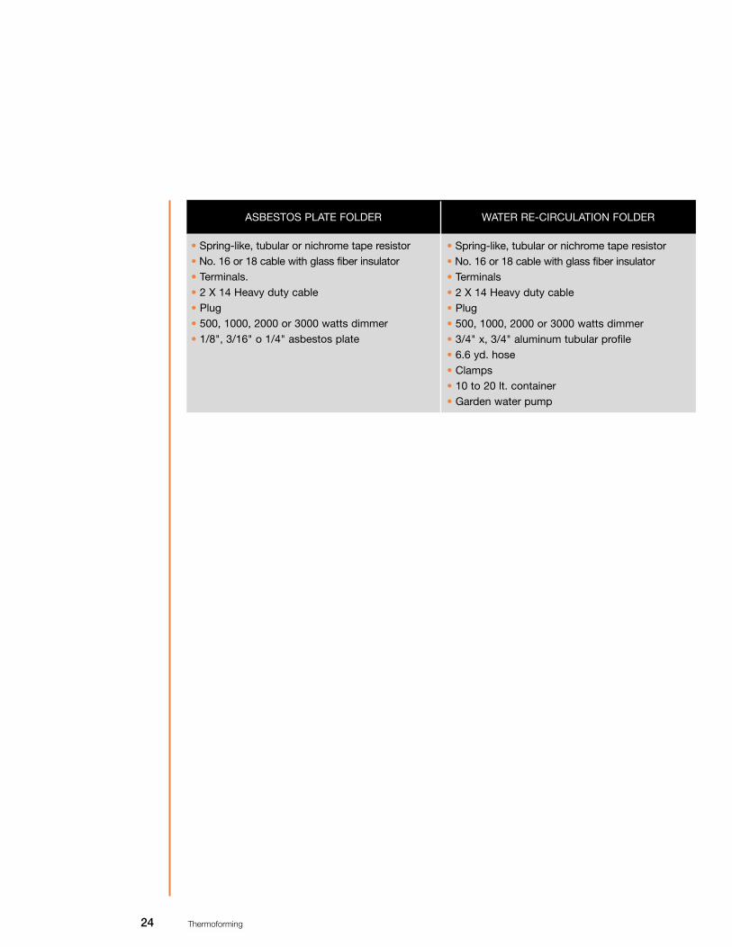
An electric resistor bender with water re-circulation will be more effective and producebetter quality bent pieces. This equipment needs tubular profiles that allow water re-circulation, which will keep the surface cool and will only allow a heating zone. Therequired materials to build this kind of bender are listed below.
It is important to include a rheostat to control temperature intensity on an acrylic sheet,since it will provide the suitable pace of production and, obviously, it will reduce costsof electric energy.
24 Thermoforming
ASBESTOS PLATE FOLDER WATER RE-CIRCULATION FOLDER
• Spring-like, tubular or nichrome tape resistor• No. 16 or 18 cable with glass fiber insulator• Terminals. • 2 X 14 Heavy duty cable • Plug • 500, 1000, 2000 or 3000 watts dimmer• 1/8", 3/16" o 1/4" asbestos plate
• Spring-like, tubular or nichrome tape resistor • No. 16 or 18 cable with glass fiber insulator• Terminals• 2 X 14 Heavy duty cable • Plug • 500, 1000, 2000 or 3000 watts dimmer• 3/4" x, 3/4" aluminum tubular profile• 6.6 yd. hose• Clamps• 10 to 20 lt. container• Garden water pump

25 Thermoforming
Complementary equipment: vacuum, pressuredair and mechanical forces
The thermoforming process consists in heating and softening a sheet of any kind ofthermoplastic material and making it adopt the form of the corresponding mold to getan almost finished product with a particular form.
Some times, an external force has to be used to turn a flat sheet into a different formand to make it copy the outline and details of the mold. The level of energy or use ofthis force must be adjusted, so that the plastic sheet can be easily forced to takeanother form.
The most common used forming forces in the thermoforming process are: vacuum orpressured air, mechanical forces and the combination of these three. Choosing a form-ing force in the forming process generally depends on the size of the product, the vol-ume to be produced and the speed of the forming cycles.
In addition, the following factors must be considered, since any of these can make adifference in selecting the forming force:
a) Intrinsic limitations of each thermoplastic materialb) Construction and material of the moldc) Thermoforming equipment available
The oldest method to form a plastic sheet into a utilitarian piece is vacuum forming. Theoriginal description of the thermoforming process was precisely "vacuum-forming".
The basic principle of the vacuum-forming process is having a softened thermoplasticsheet in a mold perfectly sealed and where the air inside is evacuated by the vacuumforce or suction. As the air is evacuated from the mold, it creates a negative pressure
Vacuum forming
on the surface of the sheet and therefore,natural atmospheric pressure yields, forc-ing the hot sheet to take the place of theempty spaces, as it can be seen in thepicture.
Acrylicsheet

26 Thermoforming
Vacuum equipmentThere is a great variety of vacuum pumps: reciprocal piston, diaphragm, blades, eccen-tric rotor, etc. All these provide a good vacuum but cannot evacuate great volumes ofair at high speed; that is why a stock tank has to be connected to be used as "vacu-um accumulator". On the other hand, there are compressors that can evacuate a greatvolume of air but are limited for vacuum force.
A suitable vacuum system needs a pump that can displace from 28 to 29" Hg or from0.5 to absolute 1 Psi (710 to 735 mm of Hg.) in the stock tank before the forming cycle.
The line, duct or pipe between the stock tank and the mold should be as short as pos-sible with a minimum of angles. It is important to eliminate air leaking due to damagedpiping, perforated hoses, loose couples or nipples, as well as unnecessary valves.
Rapid action or globe valves should be used. Vacuum pumps are available in one ortwo steps. A two step vacuum pump can evacuate pressures below 10 Psi; displace-ment capacity or evacuation for a one step pump is reduced by half. Table 11 showsvacuum pumps typical capacities
Table 11: Vacuum pump typical specifications
SPECIFICATIONS VACUUM THEORETICAL CAPACITY
No. OFCYLIN-DERS
12 2 2 2 3
DIAMETER(inches)
3.04 3.04 4.08 5.08 5.6 5.6
RUN(inches)
2.8 2.8 2.8 3.2
4.08 4.08
POWER
NEEDED
(Kw)
0.56 0.74 1.48
2.2/3.73.7 5.6
DIAMETER
OF PIPING
OUTLET
19 25 32 38 52 52
TWO STEPS
(yd3/min)
----0.2800.4980.935 1.54 3.08
ONE STEP(yd3/min)
0.2800.5610.996 1.87 3.084.64
SPEED
(RPM)
800 800 800 750900 900
Vacuum tanksExcepting some vacuum equipments, most have a stock tank. Bearing in mind thatwork pressure is about 10 Psi (about 21 inches Hg/530 mm. Hg) vacuum, then the vol-ume of the tank should be 2.5 times bigger than the volume between the molds, thevacuum box and the piping. Doubling the volume of the stock tank (along with othersimilar conditions) pressure can be increased 15% (11.5 Psi), according to what isestablished, the theoretical limit for the vacuum forming process is only 14.5 Psi.

27 Thermoforming
Stock tank (400 lt.)
2” flexible hose
globe valve
Solenoid valve Air deflector
Bearings
In many cases, a rapid displacement of vacuum is very important. This can only bemade by placing the vacuum tank as near the mold as possible and reducing the pip-ing friction as much as possible, which can be done by:
a) A bigger piping diameter.b) Piping with wide curves, avoiding 90° angles.c) Changes in the transversal section of the piping (diameter changes).
Many equipments in the market do not meet these requirements. In general, the pipingmust be 1" diameter to displace 1 ft3 of air, for big pieces a 2" or 3" diameter is suit-able. There should also be a flexible plastic hose internally reinforced with wire or asimilar material that prevents it form collapsing; it should be connected between themold and the piping, as shown in the picture.
Vacuum forces, applications.In general, pumps work constantly to keep vacuum in the stock tank, there is a varia-tion on the vacuum-meter readings in each cycle. The vacuum generated on theformed part must be kept enough time to cool and stand the internal force of the mate-rial which will tend to keep the original form, causing waves and bending.
As a general rule, the faster the vacuum is made the better the piece will be formed.Occasionally, slow forming speed for deep forming pieces or intricate sections is rec-ommended. When the matrix is very deep and when the configuration is problematic,slow vacuum can allow plastic more time to contract in the transversal section, thisway a deficient configuration can be avoided.

28 Thermoforming
In operations where vacuum force is replaced by pressured air, it should be consideredthat it is harder to seal the mold satisfactorily. The forming force can easily multiply upto 10 times if the pressured air is at 100 Psi. However, the molds can stand such pres-sure very few times.
To form by using pressured air, it is necessary to take as many precautions as possi-ble. A regular size mold requires a closing pressure of some tons, which obviously acommon vise (type "C") cannot stand. Then, various clamps or rapid action fasteners,which are very useful in this case, should be used. With the pressure exerted, a badlybuilt mold may explode like a bomb. An aluminum or machine finished metal mold is agood choice; resin or wooden molds must not be used unless they are reinforced withmetal.
Pressure forming equipment must be stronger than the vacuum forming one. It musthave a similar tank for the compressor as well. Piping does not need strict specifica-tions since pressure drop is not considerable. If in a piping pressure drops 5 Psi, pres-sure loss in the system will be 10 Psi, 50% of the pressure. But if the pressure systemis 100 Psi, it will be 5%. A valve to reduce pressure and a manometer should be alsoinstalled, as well as a baffle or filter at the entrance of the mold, so that cold air is neverin direct contact with a hot sheet. Some times, heaters should be incorporated to theair system, since they will help in great blows, which must be kept hot until a piece isformed on the mold.
If possible, there should also be filters to eliminate water that tends to condense in thesystem and in the long run can make the equipment rusty, in addition, combined withair particles, it can block air ventilation orifices in the molds. Periodical maintenance isa must.
Pressured airforming.
When needed, the mold should have ori-fices to eliminate the air caught insideand avoid wrinkles or deficient forming.
Pressured air forming has become popu-lar, specially for small pieces. The advan-tages of this method are: improvementon dimensional tolerance, forming speedcan be considerably increased and finedetails are better defined.
Acrylic
Acrylic
Mold
Mold
Vacuum orifices
Air exhaust
Vacuum
Pressured air
29 Thermoforming
Mechanicalforming
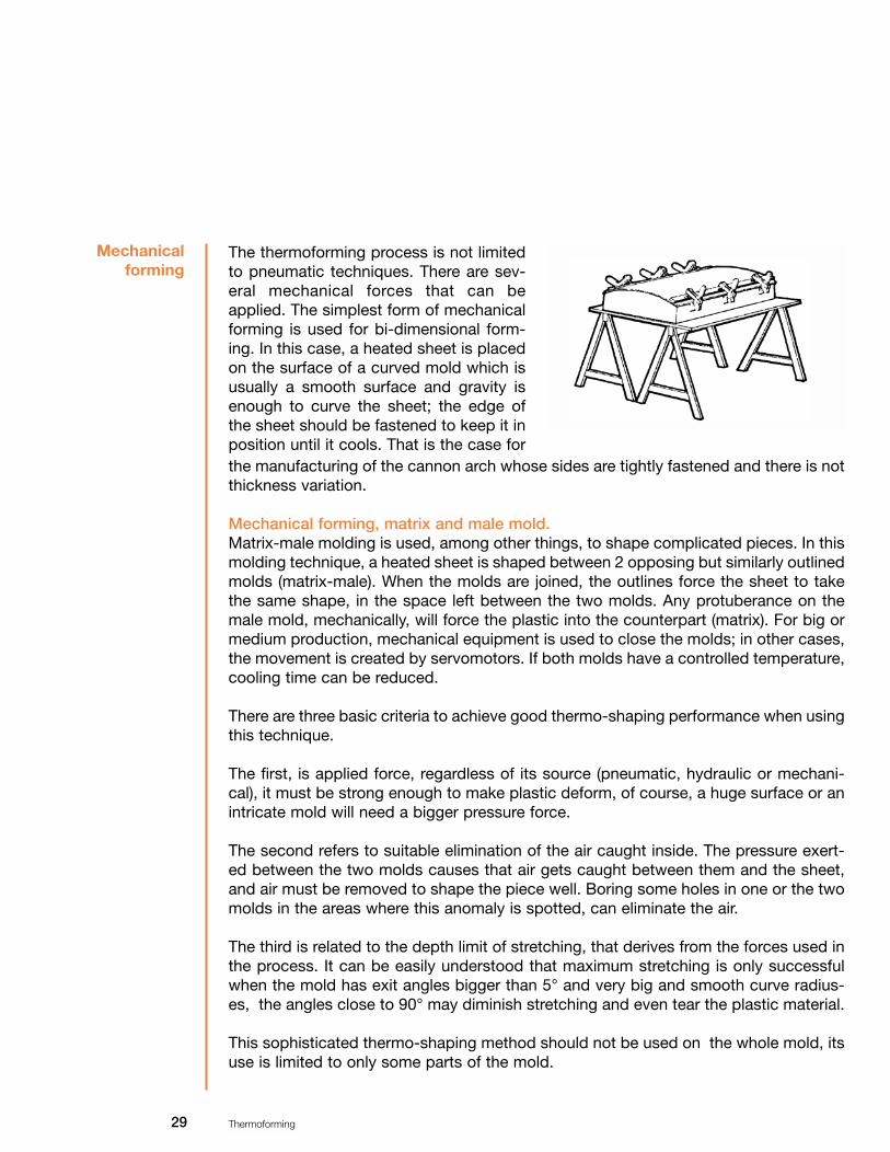
The thermoforming process is not limitedto pneumatic techniques. There are sev-eral mechanical forces that can beapplied. The simplest form of mechanicalforming is used for bi-dimensional form-ing. In this case, a heated sheet is placedon the surface of a curved mold which isusually a smooth surface and gravity isenough to curve the sheet; the edge ofthe sheet should be fastened to keep it inposition until it cools. That is the case forthe manufacturing of the cannon arch whose sides are tightly fastened and there is notthickness variation.
Mechanical forming, matrix and male mold.Matrix-male molding is used, among other things, to shape complicated pieces. In thismolding technique, a heated sheet is shaped between 2 opposing but similarly outlinedmolds (matrix-male). When the molds are joined, the outlines force the sheet to takethe same shape, in the space left between the two molds. Any protuberance on themale mold, mechanically, will force the plastic into the counterpart (matrix). For big ormedium production, mechanical equipment is used to close the molds; in other cases,the movement is created by servomotors. If both molds have a controlled temperature,cooling time can be reduced.
There are three basic criteria to achieve good thermo-shaping performance when usingthis technique.
The first, is applied force, regardless of its source (pneumatic, hydraulic or mechani-cal), it must be strong enough to make plastic deform, of course, a huge surface or anintricate mold will need a bigger pressure force.
The second refers to suitable elimination of the air caught inside. The pressure exert-ed between the two molds causes that air gets caught between them and the sheet,and air must be removed to shape the piece well. Boring some holes in one or the twomolds in the areas where this anomaly is spotted, can eliminate the air.
The third is related to the depth limit of stretching, that derives from the forces used inthe process. It can be easily understood that maximum stretching is only successfulwhen the mold has exit angles bigger than 5° and very big and smooth curve radius-es, the angles close to 90° may diminish stretching and even tear the plastic material.
This sophisticated thermo-shaping method should not be used on the whole mold, itsuse is limited to only some parts of the mold.

30 Thermoforming
Mechanically forming with matrix-male molds does not only depend on the forcesused, usually, this kind of forming can be combined with vacuum, pressured air or bothat the same time. Therefore, the matrix-male mold does not have to coincide accu-rately, the male mold may be relatively inferior in dimensions and have a substantiallydifferent form from the matrix.
When male molds are made like this, they can act as "pushers" of a plastic sheet. Thiskind of support is called mechanical support, because it presses the softened materi-al into the matrix. The purpose of this support is to stretch the material so that the finalform is accomplished in combination of vacuum and/or pressured air.
Using mechanical support in the process has the advantage of a better distribution ofthe thickness of a product, than using any other process. Many variations in theprocess can be obtained combining these techniques. Those variations can be vacu-um pressure changes, vacuum or pressure application time, mold closing speed timeor forming cycles.
Usually, mechanical supports are made of wood. Hard or tropical wood is the mostused to make supports. In some cases, pieces of other plastic material such as: nylon,rigid polyurethane, acrylic, aluminum or steel, which are easily machine finished, canbe incorporated.
If production volume requires it, a cooling and/or heating system can be incorporated.The decision to heat or cool the support, must be made from the beginning of thedesign, since later on it will be harder if not impossible to try to adapt a heating ele-ment, that is why required machine finishing should be made to incorporate the sys-tem.
When a support is very cold, a sheet will surely get cold on it. Cooling usually takesplace between the points of a support and a sheet and the sheet and the mold. Inextreme cases, the sheet may shrink on the support during the forming.
The form of a support has a determininginfluence on the wall or thickness of a fin-ished piece. In the next picture, there arethree different kinds of support.
Combinedtechniques
Mechanicalsupport design

31 Thermoforming
Flat surfaced and bluntedged support
Tin-like support Sphere-like support
Flat surfaced and blunt edged supportThis allows a sheet to stretch between the support and the edge of the mold, andmeanwhile, the part of the sheet in contact with the edge of the support gets cool. Apiece formed this way will have a thick bottom and thin walls
Tin-like supportIn this second alternative, a sheet is in contact with the support and cools fast only onthe perimeter of the support. Stretching is similar to that of the flat support, but thecentral area of the support allows extra stretching.
Sphere-like supportOn the other hand, in this case, only a small area is in contact with the support. Theremight be a significant stretching as the support moves forward, therefore, the area ofthe perimeter between the edge and the support decreases.

32 Thermoforming
Choosing the type of
thermoforming technique
Criteria todesign
thermoformed products
Thermoforming molds
One of the most important aspects to be taken into consideration in thermoformingpieces is the thermoforming technique to be used. Depending on the characteristics ofthe product if the wrong technique is used, there may be problems before you can geta piece with the specifications initially determined, finished. And many times the oper-ation will fail, with the consequence of a waste of time, money and resources. Thus,before manufacturing a mold, the following should be considered:
1.- Form and dimensions of the piece.2.- Desired aspect.3.- Thermoforming technique.
Based on these factors, you can plan and anticipate possible defects in the pieces. Inthis chapter all the variables that emerge when a thermoforming mold has to be man-ufactured, are analyzed.
It must be mentioned that: products made using thermoforming technique, though thistechnique is versatile and flexible, regarding aspect and characteristics, differ fromproducts manufactured using injection molding. In the following comparative table thebasic differences can be analyzed. To conclude, to design thermoformed pieces thefollowing criteria must be established:
1. - Thinning of material should be considered, this mostly depends on form, size and technique used (chapter 8). Generally, thinning of material is directly proportional to the height of a piece.
2.- A 3° and 5° exit angle of the mold should be considered.
3. - It must be taken into consideration that a piece will contract 0.6 to 1% when it cools.
4. - In general, the surface of a thermoformed piece will be smooth, though some tex-tures can be obtained.
5.- In designing a piece, big radiuses should be included; there may be edges but they can tear the material.

33 Thermoforming
VARIABLESPROCESO
INJECTIÓN TERMOFORMING
ThicknessMold exit anglesMolding temperatureDimensional toleranceInserts
Surface finishing
Production
Mold
May create ribbings, all types ofholes, coils, etc.Scrap, material waste
Radius
Time to make a piece (design,mold, tests).Subsequent treatment and finishing
Constant0.5° to 1°
392ºF-464ºF (200°C – 240°C)Excellent
Possible insertion of elements inother materials.
Smooth surfaces or any othertexture can be obtained.
High production, hundreds orthousands of pieces a day.
Steel with alloys or expensivetreatment, complex design,
matrix-male mold.Yes.
Very little, recoverable.
Must blunt edges, about 1.5thickness of material.
From 3 to 6 months.
Any treatment or finishing, paint-ing, hot-stamping, serigraphy,
metallization, etc.
Variable3° - 5°
320ºF-356ºF (160°C – 180°C)Relatively good, not for accuracy.Mold surface can be prepared
for insertsOnly smooth surfaces, some
shallow texturesMedium, some dozens a day.
Variety of materials, rather lowcost, simple design, may use
matrix-male mold.No.
Depends on the shape, about25% waste and recoverable.
Larger radiuses, 0.4” to 2” need-ed. Depending on shape and
depth.Maximum 1 month.
Any treatment or finishing, paint-ing, hot-stamping, serigraphy,
metallization, etc.
Table 12 Basic differences between Injection and thermo-shaping processes.

34 Thermoforming
The following criteria are key factors to successfully produce thermoformed pieces.They are the core of any development, but it is also vital to thoroughly analyze theseconcepts and later we will see in detail each consideration in the design of molds.Then, these basic criteria and considerations will be the fundamental parameters tomanufacture thermoforming molds, regardless of their complexity. It should be notedthat when these molds are manufactured, the following concepts must be assessed.
1. - Form and dimensions of the piece.
2.- Aspect of the piece.
3.- Estimated production volume.
Probably the most important of these concepts is the estimated production volume,since it will depend on the definition of the kind of mold, material, finishing, thermo-forming technique, etc. Next, the model designs are shown:
Criteria todesign
thermoforming molds
1. - A male mold is easier to use, lessexpensive and more suitable to formdeep pieces. In general, a matrix shouldnot be used to form pieces deeper thanhalf the width of the piece. The matrix isused when the concave face of the fin-ished piece must not be in contact withthe mold.
2.- The molds must have enough vacuumorifices so that an annealed sheet canconform to the critical parts of the mold,the vacuum orifices have to be made inthe deepest parts and areas where air iscaught, and must be small enough not toleave marks (1/32" to 1/8" diameter).Vacuum can be more effective if the holeis enlarged from the inside.
3.- There must be ducts that allow wateror oil circulation through the mold whentemperature control in it is needed.

35 Thermoforming
4. - When the dimensions of a formedpiece are critical, molds must be built big-ger to compensate for the contraction ofthe material.
Expected contraction from molding tem-perature to environment temperature is1% maximum.
5.-A slight curving of the flat big areas ofthe mold will allow flat areas when thematerial cools.
6. - Pieces with 90° walls cannot beobtained; the mold must have an exitangle of at least 3°.
7. - Edges should be blunt, since vertexform accumulates internal efforts. A piecewill be more resistant designing bluntedges and corners.
8.- The thin or weak parts can be rein-forced with reinforcement ribs, which willalso reinforce big flat areas.
30

36 Thermoforming
9.- If it is necessary to mold using a per-manent incrustation, you should consid-er: the difference between the expansioncoefficient and the various materials, oth-erwise, there can be a failure due to aforced insert, because of different expan-sions and contractions of the materials incontact.
10.- The surface of the molds can be linedwith cotton flannel, felt, velvet, suede, etc,to diminish mold marks. The most com-mon is cotton flannel.
Considerationsin the design ofthermoforming
molds
One of the advantages of the thermoforming process is the diversity and kinds ofmolds that can be made at a very low cost and relatively fast, being highly acceptedfor other applications, over other processes.
Usually and unlike injection molds, only half the mold is needed and it depends on theform of the product, desired aspect and chosen technique (may be male mold ormatrix).
Choosing the right one is much more important when the part to be thermoformed isvery deep. When the pieces are shallow, profiles are small or when thinning is irrele-vant, choosing will depend on the aspect of the piece. If details of the mold are impor-tant, then the side of a plastic sheet in contact with the mold surface should be thefront of the piece.
Some times, a bigger radius or smooth aspect is desirable if a sheet of material showsa nice surface, then the surface which does not touch the mold will be the front of thepiece, besides, a dimensional control closer to the surface of the mold can beobtained.
Thinning of the materialUnder every condition of thermoforming when pieces are formed of a plastic sheet, thearea of the surface will get bigger, there will be some stretching and the material willget thinner.
One of the decisive factors of this thinning is the ratio, generally defined as maximumdepth or height ratio with a minimum space through the opening. To estimate this thin-ning, the area of the available sheet to be thermoformed must be determined and divid-ed into the area of the finished piece, including waste. It is always desirable that the

37 Thermoforming
molds and thermoformed pieces have generous curving radiuses. Theoretically, thereis a formula to determine the thinning percentage of the material, considering that thematerial is uniformly annealed and stretched.
A=3B=4C=2D=1E=1
A=3B=4C=2D=1E=1
In practice, with a micrometer or calibrator you can determine thickness directly on thethermoformed piece, cutting small pieces on different sections. Other methods usetranslucent sheets and correlate color intensity vs. thinning of the sheet. Thickness canalso be determined making squares with an oil marker on the sheet before thermoform-ing it and observing stretching of the material.
Thinning % = = =Final thickness of the materialOriginal thickness of material
available area of a sheettotal area of shaped piece
A X BA X B X E (2C + 2D)
One should consider the possibility ofwrinkling on some critical areas or on thebottom of a male mold or matrix. If anannealed sheet cannot contract from thedimension A to E, excess material will cre-ate wrinkles.
In a matrix the opposite happens, thesheet will expand to the 4 vertexes of themold surface, becoming very thin. Thiscan be seen in most of the thermoformedtubs.
38 Thermoforming
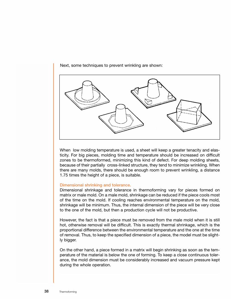
Next, some techniques to prevent wrinkling are shown:
When low molding temperature is used, a sheet will keep a greater tenacity and elas-ticity. For big pieces, molding time and temperature should be increased on difficultzones to be thermoformed, minimizing this kind of defect. For deep molding sheets,because of their partially cross-linked structure, they tend to minimize wrinkling. Whenthere are many molds, there should be enough room to prevent wrinkling, a distance1.75 times the height of a piece, is suitable.
Dimensional shrinking and tolerance.Dimensional shrinkage and tolerance in thermoforming vary for pieces formed onmatrix or male mold. On a male mold, shrinkage can be reduced if the piece cools mostof the time on the mold. If cooling reaches environmental temperature on the mold,shrinkage will be minimum. Thus, the internal dimension of the piece will be very closeto the one of the mold, but then a production cycle will not be productive.
However, the fact is that a piece must be removed from the male mold when it is stillhot, otherwise removal will be difficult. This is exactly thermal shrinkage, which is theproportional difference between the environmental temperature and the one at the timeof removal. Thus, to keep the specified dimension of a piece, the model must be slight-ly bigger.
On the other hand, a piece formed in a matrix will begin shrinking as soon as the tem-perature of the material is below the one of forming. To keep a close continuous toler-ance, the mold dimension must be considerably increased and vacuum pressure keptduring the whole operation.

39 Thermoforming
As a guideline it can be assumed that shrinkage on male molds it is .127 mm/mm(0.005 in/in) and in a matrix it is bigger. For acrylic, polycarbonate, thermoplastic poly-ester and oriented polystyrene .203 mm/mm (0.008 in/in) can be considered. Anyway,one should be cautious about these values, since the following conditions can signifi-cantly alter them.
1.-Mold temperature: a difference of 15°F (10°C) can change shrinkage over 0.001 in/in. (0254 mm/mm).
2.- Size and thickness: this refers to the exit angle limited by the mold and the effect of greater thickness regarding temperature profile.
3. - Final use temperature: Due to expansion and contraction proportional to lineal expansion coefficient, a thermoformed piece will keep on varying with environmen-tal temperature changes.
4.- Use extreme conditions: Shrinking can reach top values after the first exposition to the highest temperature of use.
5.- Molecular orientation: There might be bigger shrinkage related to the molecular ori-entation of the material.
Some times, to prevent distortion and shrinkage, cooling templates are needed until apiece reaches the environmental temperature. Further more, the pieces thermoformedat a temperature below the one specified, tend to go back to their original state due tothe plastic memory of the material. It is advised to monitor shrinkage and deformationduring production.
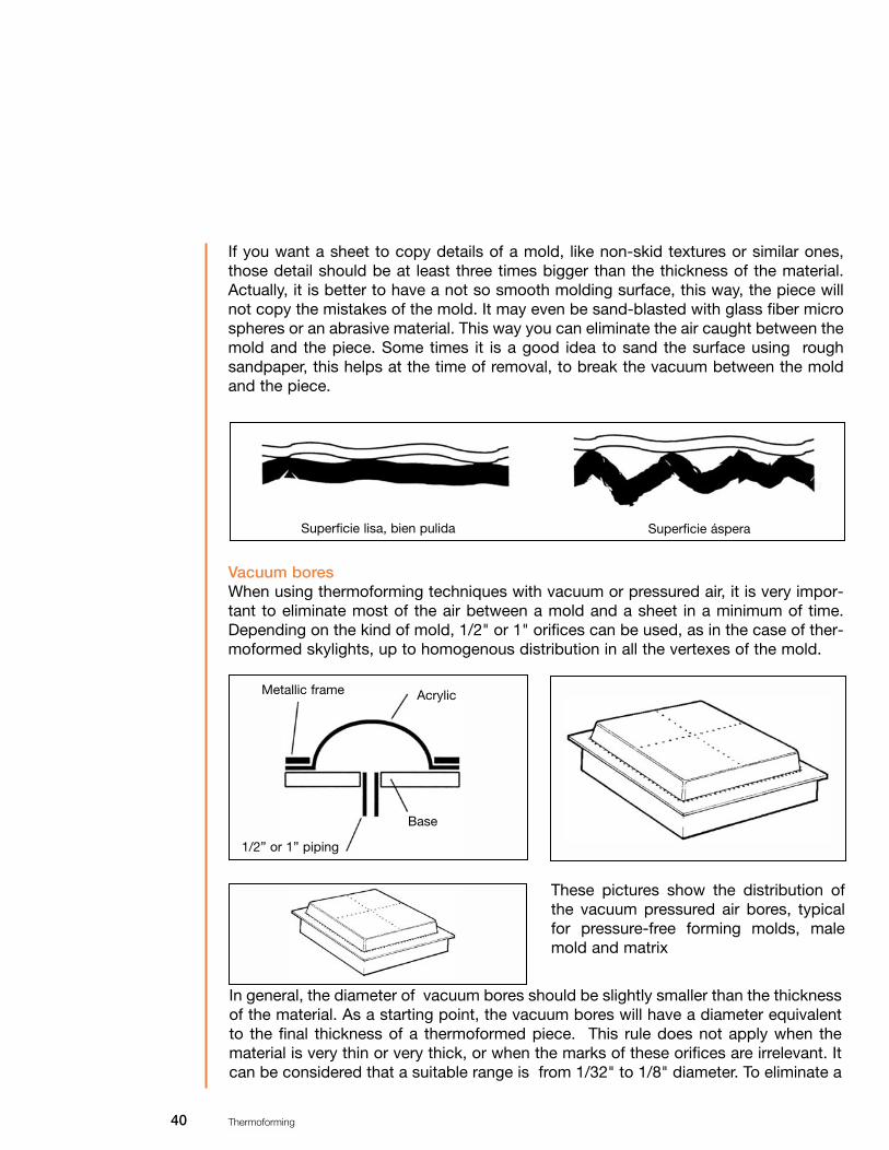
Aspect of the mold.It must be clarified that the surfaces obtained by injection and extrusion processescannot be reproduced by conventional thermoforming techniques. Even highly brilliantmaterials may lose their glow during the process. In addition, they tend to emphasizemark and waving when they touch a cold mold and undergo thickness changes. Achange of thickness will cause small distortions. Thus, cleaning the working area is amust. All the outlines should be rounded, actually, a mold with big radiuses will bene-fit the thermoforming operation, since the material will tend to stretch better
NO YES
40 Thermoforming
If you want a sheet to copy details of a mold, like non-skid textures or similar ones,those detail should be at least three times bigger than the thickness of the material.Actually, it is better to have a not so smooth molding surface, this way, the piece willnot copy the mistakes of the mold. It may even be sand-blasted with glass fiber microspheres or an abrasive material. This way you can eliminate the air caught between themold and the piece. Some times it is a good idea to sand the surface using roughsandpaper, this helps at the time of removal, to break the vacuum between the moldand the piece.
Superficie lisa, bien pulida Superficie áspera
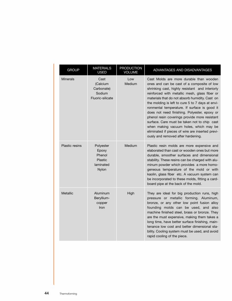
Vacuum boresWhen using thermoforming techniques with vacuum or pressured air, it is very impor-tant to eliminate most of the air between a mold and a sheet in a minimum of time.Depending on the kind of mold, 1/2" or 1" orifices can be used, as in the case of ther-moformed skylights, up to homogenous distribution in all the vertexes of the mold.
These pictures show the distribution ofthe vacuum pressured air bores, typicalfor pressure-free forming molds, malemold and matrix
Metallic frame
1/2” or 1” piping
Acrylic
Base
In general, the diameter of vacuum bores should be slightly smaller than the thicknessof the material. As a starting point, the vacuum bores will have a diameter equivalentto the final thickness of a thermoformed piece. This rule does not apply when thematerial is very thin or very thick, or when the marks of these orifices are irrelevant. Itcan be considered that a suitable range is from 1/32" to 1/8" diameter. To eliminate a

41 Thermoforming
Another function of a mold is to contribute along with a frame to stabilize the positionof a sheet and provide good sealing all around the mold. In some cases, a canalaround the piece is helpful, exactly on the external zone of the cutting line.
Mold coolingSome times when production runs are very long, the mold should have a cooling sys-tem, generally copper piping is used. It should be placed adequately and have enoughcapacity to carry a considerable volume of water or refrigerant. A relationship betweenthe temperature of the sheet and the mold should be established so that the materialdoes not get too cold and it does not thermoform below the bottom limit of the mold-ing temperature.
There are different methods to cool a mold, for example, when there are critical mold-ing zones, plastic or poly-tetra-fluorine-ethylene inserts can be incorporated. In somecases, a plastic covering can be applied to reduce thermal conductivity, or even afterthermoforming, pressured air can be injected through the bores or holes. Three cool-ing systems are shown in the next picture: First an undulated cooling system, the sec-ond is a branch system and the third is an external multiple alternative flow branchsystem with 2 inputs and 2 outputs.
Widened bores onthe inside
Increased diameterbore
great volume of air, 1/8" or _" diameter holes can be drilled. Depending on the manu-facture of the mold, the bores can be widened on the inside of the mold, as shown inthe picture. To reduce the time to eliminate the volume of air round a softened sheetand a vacuum box, the space can be refilled with polystyrene foam balls orpolyurethane pieces.
Undulatedsystem
Branch system
External multiplealternative flowbranch

42 Thermoforming
Mold supportsAs it has been mentioned before, when thermoforming a piece the material always getsthinner. Molding supports are used to get a better distribution of material in a thermo-formed piece. Their purpose is to stretch a softened sheet, as a pre-forming. This tech-nique is very important, specially with very deep pieces. In general terms, the moldingsupports can be made of the same material as molds. There are three categories ofmold supports:
Metallic supportsUsually they are made of iron or aluminum, must be very smooth, with radius on theedges. The range of temperature is 10 to 15°C (10°F) below the temperature of thematerial, if their temperature is too high the sheet will stick to them.
Thermal material supportsThese are made of wood, plastic or metal and they are built under the principle of agood thermal insulator. The surface may be of soft wood, plastics like nylon, or anoth-er thermofixed, synthetic foam or any other material including soft flannel.
Skeleton type supportSkeleton or frame type supports are only rounded bars welded forming intersections,which should be totally rounded to avoid tearing the material.
Support dimensions are related to the size of a piece, since they have a great influ-ence on the thickness distribution of the material. It must be noted that in somecases, by only changing the depth penetration of a support (75% depth of the piece),the thickness of the material between the faces and the surface can be controlled.Therefore, the equipment must have the required depth adjustment capacity, pene-tration power and speed.
Materials used.Unlike other plastic molding processes, such as injection or compression, thermo-forming has the advantage of using relatively low pressure and temperature. That iswhy a great variety of materials can be used. Usually, wooden molds can be used, theyare ideal for low production and as wood has a low thermal conductivity, it helps theannealed sheet not to cool quickly at first contact, but these molds are not good formedium or high production. Manufacturing molds with phenol laminates are betterbecause they are not seriously affected by heat or humidity.
There are also molds made of mineral or metallic charges and polyester or epoxy orrigid polyurethane resins. These are easy to remove off a mold and may even have amold with multiple cavities. The thermal properties of epoxy and polyester resins makethem suitable for medium production. Copper piping can be used as cooling system tobetter control the mold temperature, but even then, it is not enough for high production.
Materials usedto manufacturethermoforming
molds

43 Thermoforming
Aluminum molds are the best for high production, but because of the thermal conduc-tivity of aluminum, the mold has to be pre-heated by means of circulating hot waterthrough the cooling/heating system or radiating heat with electric resistors, or evenheating the mold with the same material to be thermoformed. For long runs, a thermo-stat has to be incorporated, to ensure there is the least temperature fluctuation on thesurface of the mold, thus, preventing over cooling. Applying poly-tetra-fluorine-ethyl-ene to aluminum can improve its properties.
Summarizing, there are 4 groups to manufacture thermoforming molds:
1) Wood.2) Minerals.3) Plastic resins.4) Metals.
Table 13. Use of materials for thermoforming molds
GROUP MATERIALSUSED
PRODUCTIONVOLUME
ADVANTAGES AND DISADVANTAGES
Woods PineMahogany
CedarMapleTriply
Agglomerated
Low These are low cost molds, their time ofmanufacturing is short and they havegood surface finishing, though in somecases the grain of the wood leavesmarks. Wood should be seasoned, forbetter finishing and preventing dimen-sional changes due to humidity, moldsmust be sealed with casein, phenol-varnish or epoxy resin diluted in methyl-ethyl ketone. For better finishing thegrain of the wood must be parallel tothe length of the mold. Triply or agglom-erated molds last longer, which can beprolonged by reinforcing the intersec-tions with metal.
44 Thermoforming
GROUP MATERIALSUSED
PRODUCTIONVOLUME
ADVANTAGES AND DISADVANTAGES
Minerals
Plastic resins
Metallic
Low Medium
Medium
High
Cast (Calcium
Carbonate)Sodium
Fluoric-silicate
PolyesterEpoxyPhenolPlastic
laminatedNylon
AluminumBeryllium-
copperIron
Cast Molds are more durable than woodenones and can be cast of a composite of lowshrinking cast, highly resistant and interiorlyreinforced with metallic mesh, glass fiber ormaterials that do not absorb humidity. Cast onthe molding is left to cure 5 to 7 days at envi-ronmental temperature. If surface is good itdoes not need finishing. Polyester, epoxy orphenol resin coverings provide more resistantsurface. Care must be taken not to chip castwhen making vacuum holes, which may beeliminated if pieces of wire are inserted previ-ously and removed after hardening.
Plastic resin molds are more expensive andelaborated than cast or wooden ones but moredurable, smoother surfaces and dimensionalstability. These resins can be charged with alu-minum powder which provides a more homo-geneous temperature of the mold or withkaolin, glass fiber etc. A vacuum system canbe incorporated to these molds, fitting a card-board pipe at the back of the mold.
They are ideal for big production runs, highpressure or metallic forming. Aluminum,bronze, or any other low point fusion alloyfounding molds can be used, and alsomachine finished steel, brass or bronze. Theyare the must expensive, making them takes along time, have better surface finishing, main-tenance low cost and better dimensional sta-bility. Cooling system must be used, and avoidrapid cooling of the piece.

45 Thermoforming
Recommendations for thermoforming molds 1. For wooden molds, the best remover is baby powder or flour.2. For metallic or plastic resin molds, removing waxes are recommended.3. Soft wood must not be used with very sensitive materials such as polystyrene,
foamed or acrylic P.V.C., since they get marked because of the grain of the wood.4. For long production runs, wood must not be used since slow cooling makes the
mold expand, creating separations on the joints.5. For plastic resin or metallic molds, aerosol removers can also be used.6. For wash basins, tubs, or bath room modules, a porcelain-like glow can be achieved
sand-blasting the surface of the mold, roughness will achieve a finish with these characteristics.
.

46 Thermoforming
Bi-dimensionalthermoforming
Thermoforming techniques
Thermoforming is the simplest and most used process to form an acrylic sheet. Beinga thermoplastic material it softens and it is easy to handle and can take any form whenheated at suitable temperature and time.
As it cools it recovers its rigidity and keeps the form it was exposed to. The cost ofequipment and molds is relatively low and bi or tri-dimensional forms can be obtainedby means of a great variety of processes.
This is a bending process that can be achieved through two methods:
Lineal heating bending.A Chemcast acrylic sheet is heated on a lineal resistor, bending at the desired angle.To bend, remove the protector paper of the bending line (the rest of the paper may beleft to protect the areas that are not to be worked on), then place the sheet on the sup-ports with the bending line directly on the heating line, bending on the heated side.Heating time varies according to the thickness of a sheet. To bend an acrylic sheet over0.16” thick it should be heated on both sides to obtain a suitable bend. Heat the sheetuntil it gets soft on the bending zone. Do not try to bend the sheet before it is well heat-ed, this may cause irregular or creased corners.
Heat carefully, irregular heating may cause arching on the bending line. Some timesthis is hard to avoid, specially on pieces over 24” long. Arching may be diminished fas-tening the recently formed material with some clamps or a template until it cools.Templates can be made of wood, fixed or adjustable.
With suitable heating,clean shining cornersare obtained
Place the sheet on thesupport with the fold-ing line directly on theheating line
Use fixed oradjustable templatesto keep the piece atthe desired angle
YES No
Acrylic Acrylic
Electric resistor
Top
Butts
Support withadjustable hinge
at any angle

47 Thermoforming
Cold forming
Chemcast acrylics sheet can be cold formed on curved frames, as long as the radiusof the curve is 180 times bigger than the thickness of the material used.
Formula: R (radius) = 180 X T (Thickness of material in inches.)
Three-dimensional
thermoforming (with molds).
R=180 X E
The procedures for tri-dimensional forming in general, require using vacuum, pressuredair, mechanical equipment, or a combination of these to mold Chemcast acrylic sheetsto a desired form. These techniques are described next:
Free or gravity shapingThis method is the simplest of all,because once the material is softened,the sheet is placed on the mold and thematerial adopts the form by its ownweight. The edges of the material can befastened to the mold to avoid waves thattend to occur when cooling.
Mechanical forming with matrix andmale mold.A Chemcast acrylic sheet can be formedpressing the annealed material betweenthe male mold and the matrix, to producepieces of very accurate dimensions. Thisprocedure requires excellent finishing ofthe molds to reduce their marks to a min-imum.
Acrylic
Mold
Frame
Male mold
Matrix

48 Thermoforming
Free, pressure or vacuum formingThe pieces that require optical clarity likeskylights, helicopter cabins, etc., can beformed without mold, Chemcast acryliccan be vacuum or pressured air formed.The form of the finished piece is given bythe form and size of the ring that fixes it tothe frame and by the given height.However, these forms are limited tospherical outlines or bubbles freelyformed. Vacuum is better for this kind offorming, or pressure if it is over 1 atmos-phere.
Vacuum and pressure forming, matrix. This procedure allows forming pieces, on1 piece molds whose form requires moreaccuracy than the ones vacuum formed.However, high pressure leaves marks ofthe mold on the piece. As high pressure isrequired, the molds should be of metal,epoxy resins or other materials that canstand high pressure without deforming.Good finishing of the molds is a must toobtain quality pieces.
Pressure forming with the help of a pis-ton and matrixThe technique of piston help is used toreduce thinning at the bottom of theformed pieces. The piston stretches thematerial before pressure is applied. Pistonspeed of 6.6 yd./min., is required, it maydamage the material at initial contact.Forming pressure 6.16 pounds/in2
Presión de aire
Vacío

49 Thermoforming
Vacuum with return and male moldforming. This technique is useful to form piecesthat require uniform thickness on thewalls and fewer forming marks. Anannealed sheet is stretched in a vacuumbox until it reaches the necessary depthfor the mold; once it is inside it, vacuumis freed gradually so that the acrylicreturns to its original form meeting it.More defined forms can be obtained if atthe point of returning, vacuum is appliedto the male mold
Pressure forming with the help of a pis-ton, matrix and vacuum.This is the most sophisticated of all, sinceit is a combination of almost all the oth-ers, it is generally used for very deepthermoforming which requires more con-trolled thickness and when breaking ispossible because of excessive moldingdepth.
Vacío
Vacío
Vacío
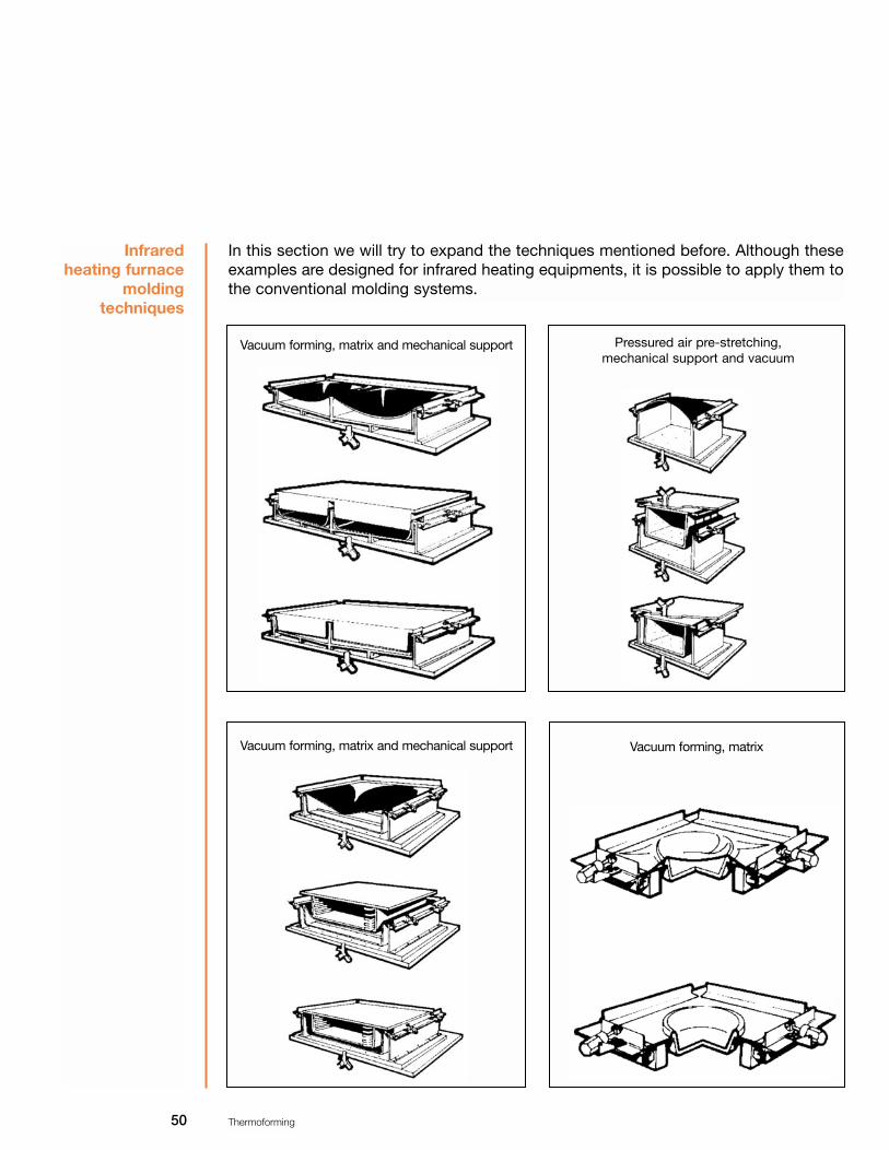
50 Thermoforming
In this section we will try to expand the techniques mentioned before. Although theseexamples are designed for infrared heating equipments, it is possible to apply them tothe conventional molding systems.
Infrared heating furnace
molding techniques
Vacuum forming, matrix and mechanical support
Vacuum forming, matrix and mechanical support Vacuum forming, matrix
Pressured air pre-stretching,mechanical support and vacuum

51 Thermoforming
Pressured air pre-stretching, matrix,mechanical support and vacuum
Pressured air stretching, mechanical support and vacuum
Vacuum forming, matrix, mechanical support and pressured air.
Free pressured air forming
Free pressured air forming

52 Thermoforming
Cooling thermoformed pieces
Cooling a thermoformed piece is as important as heating it, but in some cases, it takeslonger than heating. That is why it is important to choose the right method. Sometimes, when very thick pieces that can stand less internal effort are formed, normalcooling should be delayed, covering the piece with soft cloth or flannel. If the piece isfastened with clamps, fastening force diminishes as cooling takes place and shrinkagewill show the great efforts of this process.
Most of the heat absorbed during the heating cycle should dissipate off the plasticbefore it is removed off the mold, otherwise, the piece might get distorted and warped.If the piece is formed on a male mold, it should be removed before shrinkage, whichwill make it hard to remove.
Conduction and convection are practically the only methods to dissipate heat, sincethermal conductivity is low, pieces over 0.08” thick require long cooling. The mostcommon is using electric ventilators to cool the piece; this method has the advantageof allowing cooling the piece on the mold. The disadvantage is that the air draft is notenough to cool the mold in each cycle, and the mold will be too hot, interfering withthe normal heating cycle.
Cooling a piece in contact with a mold is very efficient if it is a metallic mold and hascooling ducts with water re-circulation. In these cases, enough volume of refrigerantliquid should be used to keep a constant temperature on the mold. If the cooling wateris kept at a certain temperature, marks on the piece (usually known as undulations onits surface) due to a cold mold, can be minimized. Aluminum or epoxy resin and/orpolyester molds are very suitable if you want to include a refrigeration system. Woodenmolds are not convenient for long runs because they do not dissipate heat quickly.
There are faster cooling methods that use a spray or a very thin de-ionized water cur-tain or liquid carbon dioxide, which rapidly cools a thermoformed piece. This methodis not common because of its cost, but both methods can be justified, specially if theyare applied locally to prevent thermal tearing of very deep pieces. Irregular fast coolingof a formed piece causes great efforts that affect durability.
Conventionalcooling
methods
Non conventional
cooling methods

53 Thermoforming
Cutting thermoformed pieces
Once the forming cycle is finished, pieces have to be cut to eliminate excess material.It is very rarely that a finished piece does not need cutting, as in the case of lightedsigns. Most thermoformed products need some kind of cutting.
The right equipment and technique must be chosen. Anyway, there are some factorsthat determine the choice, as sheet measures, size and depth of a piece, acceptablelevel of roughness of the cutting surface, required dimensional tolerance and cuttingspeed among others.
There are several equipments to cut thermoformed pieces:
Electric tools.
Circular saw.A circular saw must have straight teeth to help cooling and not to soften the material.Tungsten carbide teeth provide excellent cutting and keep sharp longer. Cutting mustbe slow to prevent heating or stretching the material. The saw has to be operated atrelatively high speed and before starting, make sure that the saw has reached its high-est speed. The thicker the material, the bigger the diameter of the saw must be, andhave the least number of teeth (minimum 2 teeth per 0.8”.). When a hand circular sawis used, the sheet has to be held and pressed firmly as it cuts at a steady speed toavoid chipping.
Table 14. Cutting specifications for circular, radial, or travel saw.
Cutting equipment.
SHEETThickness inches
DISK
DIAMETERS (inches) Thickness (inches) No. TEETH (*)
0.06-0.12 0.12-0.16 0.2-0.4 0.48-0.60.72-0.84
1-2.08
8 10 10 12 12
12-14
1/16-1/32 3/32-1/8
1/8 1/81/8
1/8-5/32
96 82-96 82-96 82-96 48-52 48-52
*Teeth with tungsten carbide bit, teeth with straight surface at the center, combined or alternated

54 Thermoforming
Band saw A band saw is the right one to make curves in flat sheets and rethread formed pieces.A band saw with variable speed up to 5000 feet/min. and minimum 10" deep groove isrecommended . It is convenient to use the special bands to cut metal or plastic; theguide must be adjusted as close as possible to the material to avoid chipping on thecutting line and to reduce the vibration of the saw to a minimum. Next, cutting speci-fications with a band saw are listed:
Table 15, cutting specifications with a band saw.
SHEETThickness (inches)
ENGINEBAND
WIDTH MIN(inches)
TEETH X(inch)
HP RPM
0.06-0.12 0.16-0.24 0.32-0.48
0.6-1 1-2.08
3/163/16 1/4 3/8 3/8
DE 2500
A 3500
1 1.5 1.5
1 .5-2 2
18 14 10 8 8
SHEETMINIMUM RADIUS TO CUT IN (inches)
BAND
WIDTH OFBAND (inches)
TICKNESS OF BAND (inches)
TEETH X INCHES
0.480.52-0.76 0.8-1.52 1.56-2.28 2.32-3.04 3.08-4.564.6-8.12 8.16-12.2 12.24-20
3/16 1/4 3/8 1/2 5/8 3/4 1
1 1/4 1 1/2
7 7 6 554 4 3 3
.028 .028 .028 .032 .032 .032 .035 .035 .035
Table 16 Radial cutting specifications, with band saw
Router Chemcasts acrylic sheets can be cut with a portable or fixed router (electric or pneu-matic). A 1.5 HP and 20,000 to 30,000 RPM electric router is recommended, and bitsor cutters with tungsten carbide bits with 1/4 or 3/8" diameter and ideally 1/2" to avoidthat vibrations break the bit.

55 Thermoforming
This method provides very uniform cut and is good to form as well as to make bigdiameter holes. The router can be fixed to a table and a copying guide can be used forintricate designs.
The cutting tool of a circular saw or router can be changed for an abrasive normal diskor even a diamond one; this kind of disk should not be used when an acrylic formedpiece is reinforced with glass fiber, as in the case of tubs, wash basins, phone booths,etc.
Automatic equipment.This kind of cutting equipment is used when a high automatic level is required; gener-ally, this equipment has a computing system and specialized software, like CAD-CAM-CAE, which is used to design the cutting pattern, and later send the information to aperipheral one, that in this case may be 1 or 5 head routers, pressured water systemor laser. Cutting capacity is not limited to a direction or plane, it can perform any kindof cut or perforation.
Pressured water cuttingThe abrasive system with pressured water eliminates many of the problems related tothe machinery and cutting operations of conventional cutting. A very fine jet of pres-sured water 50.000 Psi, is concentrated, at a speed of about 3.3 yd./min and a pres-sure of +/- 0.04”.
Using a combination of highly pressured water and abrasive materials, such as silicapowder, the water jet can cut every material without heating and provide an exceptionalfinishing on the cutting surface.
The advantages of this cutting system on acrylic are: eliminating heating distortions,any cutting angle can be performed because of its multi-directional type integrated tocomputing systems, it eliminates secondary operations like sanding, and reducesmaterial waste since the cutting area is very reduced.
Cutting with laserCutting with laser is a technique that has already been used in other industrial sectorsfor several years and its main characteristics are:
• High pressure cutting• Manufacturing flexibility • Reduced cost
An advantage of the laser cutting is its application versatility, since apart from its directuse to cut acrylic sheets, it offers the possibility of processing many other materials.
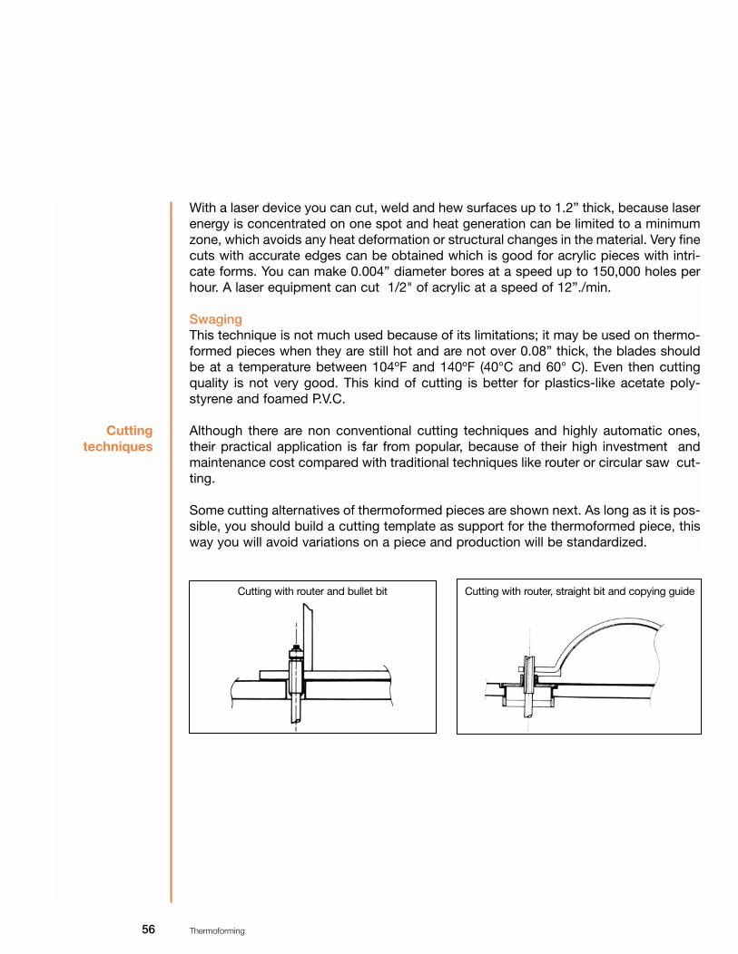
56 Thermoforming
With a laser device you can cut, weld and hew surfaces up to 1.2” thick, because laserenergy is concentrated on one spot and heat generation can be limited to a minimumzone, which avoids any heat deformation or structural changes in the material. Very finecuts with accurate edges can be obtained which is good for acrylic pieces with intri-cate forms. You can make 0.004” diameter bores at a speed up to 150,000 holes perhour. A laser equipment can cut 1/2" of acrylic at a speed of 12”./min.
SwagingThis technique is not much used because of its limitations; it may be used on thermo-formed pieces when they are still hot and are not over 0.08” thick, the blades shouldbe at a temperature between 104ºF and 140ºF (40°C and 60° C). Even then cuttingquality is not very good. This kind of cutting is better for plastics-like acetate poly-styrene and foamed P.V.C.
Although there are non conventional cutting techniques and highly automatic ones,their practical application is far from popular, because of their high investment andmaintenance cost compared with traditional techniques like router or circular saw cut-ting.
Some cutting alternatives of thermoformed pieces are shown next. As long as it is pos-sible, you should build a cutting template as support for the thermoformed piece, thisway you will avoid variations on a piece and production will be standardized.
Cutting techniques
Cutting with router and bullet bit Cutting with router, straight bit and copying guide

57 Thermoforming
Cutting with bench saw and iron or aluminum angle butt
Cutting with router and cookie cutter or abrasive disk on the outside
Cutting with router and cookie cutter or abrasive disk on the inside
Cutting with bench saw and wooden butt
Cutting with radial saw and template on the inside Cutting with radial saw and template on the outside

58 Thermoforming
Thermoforming variables
In the thermoforming process there are variables that can affect aspect, quality, dimen-sions and distribution of the material of a formed piece. Knowing these variables canhelp to solve difficult production problems in the thermoforming process. Following, themost frequent variables as deviations in the thermoforming process are shown.
Thickness of a sheetWhen electric resistors or infrared radiation is used to heat, changes on caliber of thethickness of the material can cause an uneven heating, creating variations in theformed part. In pre-stretching or deep forming, close dimensional tolerance is neededto avoid breaking the material in very thin areas, because of the force exerted by vac-uum or pressured air. In very deep pieces there is a variation in the thickness of thematerial which depends on the thickness used, the area and maximum depth of apiece. When there is a thickness variation between each sheet, the heating tempera-ture must be reduced to prevent material from over softening. If the temperature of asheet is homogeneous, even a piece with thin areas can be well made.
Sheet pigmentationIn the case of radiation heating (electric resistors) the different colors of the same mate-rial can cause temperature changes and heating cycle changes. In a convection fur-nace (hot air re-circulation) this variable does not apply..Size of a sheet.To get a better distribution of the material of a very deep piece, it is more economic toincrease the size of a sheet instead of its thickness.
Temperature uniformity of a sheetWhen the temperature of any material is increased, tension force is reduced and there-fore the sheet becomes malleable. Simple or deep forming made at a lower range thanannealing temperature provides the best results.
For high quality pieces, it is important that a sheet heats evenly at annealing pointlength-wise and width-wise. The sheets that are not evenly heated will be deficientlyformed: there will be more stretching in the normal temperature zones than in the onesthat were not softened.
Material variables

59 Thermoforming
Vacuum bores or orifices Vacuum speed is directly proportional to the quality of a piece. A slow vacuum makesthe part of the sheet where the first contact with the mold takes place to cool fasterthan the rest. Therefore, there are sections with very thin walls or incomplete pieces.To eliminate air quickly, 1/8" and _" vacuum bores should be used. When possible,there should be vacuum canals or ducts since they display a greater volume of air.
Mold surfaceWhen a thermoplastic sheet is formed it will take the form of the mold, one with opaquefinishing, will give an opaque finishing, a very polished finishing (mirror finishing) ofcourse, will provide a shining piece.
Mold temperature.A mold surface temperature influences directly the duration of the forming cycles, thesize and a better aspect of a formed piece. A thermoformed piece final shrinkagedepends on having a mold temperature similar to the thermal expansion coefficient ofthe material.
Mechanical support temperatureTo prevent a sheet from getting cold during a pre-stretching operation causing "cool-ing marks" and deformations, a mechanical support should be heated at a tempera-ture over the distortion point.
Vacuum boxIn vacuum with return and free forming it is very effective to use a vacuum box of 3.2”to 4.8” longer than the total depth of the formed bubble to prevent cooling on theperimeter of the sheet in contact with the mold. Before forming the bubble, the sheetmust be strongly sealed on the mold. In a vacuum with return operation, maximumthinning will occur at the bottom of the formed bubble. To get thicker walls, there mustbe a two step edge in the vacuum box which will cool the top area making it thicker.
Air temperatureSometimes the air of the system should be pre-heated. When air at room temperaturegets into the system, it may cool the sheet, affecting its size and form. With thin mate-rials, the cooling problem is more serious. With pre-heated air, the temperature shouldbe about 10% below the temperature of the sheet. An air deflector or an air diffusershould be used at the intake of the mold since they can prevent a sudden cooling insome areas of the material.
Mold variables
Pre-stretchingvariables

60 Thermoforming
Mechanicalsupport
variables
Mechanical support formThis must be closely adapted to the form of the cavity of the mold, but must be 10 to20% smaller length-wise and width-wise (or diameter). When these dimensions are4.8” or larger, the small supports must allow at least 1/4" margin between the final partand the support, to prevent thickness irregularities of the material as far as possible.
When the mold has canals (corrugated tin) with sudden changes from flat to narrowzones it is important that the support is made with detachable parts that fit into thecanals of the mold. These parts will help add more material to increase thickness in aparticular area. For boxes in the mold, the same projection of the support must beapplied. In the case of deep depressions on the walls of the mold, a support mecha-nism should be incorporated to take material to that zone, all the corners should besoftened and have generous radiuses.
Support materials.To get good results, the mechanical support must have excellent qualities to transferheat, and must have constant and prolonged resistance at high temperatures.Aluminum is one of the best materials. For short or prototype runs hard wood is betterand to prevent it from getting too dry or cracking because of the heat, the surface hasto be greased frequently.
Support temperature.The temperature of a support must be kept below that of the forming of a sheet. Thesupport may have low working temperatures, anyway, if the temperature drops, thecooling marks will be more visible.
It is not so critical to strictly control the temperature of a mold. In the case of a sup-port, a maximum uniform heating of 50°F must be kept without variation, with suitableregulated temperature the molding marks are generally eliminated.
Support surface.A smooth surface with well polished radiuses, dust-free and rubbish-free, will producegood pieces
Support heightAn effective mechanical support is the one that is longer than the depth of the mold,since it can regulate adjusting.
Support vacuum speed.Increasing the speed of a support raises air compression capacity in the cavity of themold. The vacuum system capacity and its duration related to the run of the supportaffects pressure in the cavity of the mold. Normally, the vacuum cycle must start at thesame time as the support touches the material.

61 Thermoforming
Support, depth of actionThe best results are achieved when a support penetrates 78 or 80% in the cavity of themold. This creates the best combination between the thickness of the bottom and thewalls of a piece.
Material variables when forming with supportThe kind of material used will affect the amount of pressure needed to keep the right con-tact of the material around the support. High resistance of materials such as acrylic andABS, need air pressure between 15 and 50 Psi.

62 Thermoforming
Problems and solutions guide
DEFECT SUGGESTED SOLUTION
• Bubble or blister on the sheet
• Incomplete forms and details
• Color change of a sheet
• Excessive moisture
• Heating too fast
• Irregular heating.
• Insufficient vacuum
• Slow vacuum displacement
• Insufficient heating of a sheet.
• Excessive heating
• Low mold temperature.
• Pre-dry sheet. • Dry both sides of sheet at
140°F (60°C)• Reduce furnace temperature. • Increase distance between
sheet and heater.• Check and fix the furnace. • Check heating elements.
• Eliminate obstructions in vac-uum system
• Increase number of holes• Increase their diameter • More tank and vacuum pump
capacity. • Leakage. • Check vacuum system for
possible leaks. • Use vacuum canals in possi-
ble areas. • Increase temperature or heat-
ing time.
• Reduce heating time.• Reduce furnace temperature.• Heat mold.
POSIBLE CAUSE

63 Thermoforming
DEFECT SUGGESTED SOLUTION
• Color change of a sheet.
• Excessive warping or bend-ing of a sheet
• Cooling marks on a formed piece.
• Low temperature of mechanical support
• Too much thinning of a sheet. • Sheet cooling before its formi-
ing is completed.
• Mold wrongly designed.
• Inadequate material
• Sheet too hot
•Sheet too big.
• Sheet too hot.
• Insufficient temperature of support.
• Mold low temperature (Shrinking stops at contact with mold or cold support).
• Heat mechanical support.
• Increase sheet thickness. • Place sheet more quickly on
the mold. • Increase vacuum speed. • Heat mold and mechanical
support. • Reduce mold depth. • Improve vacuum air flow.• Use more curved radiuses. • Change material.
• Reduce heating time. • Reduce furnace
• If possible, reduce sheet size• Use screens, mainly on cen-
ter of sheet (only infrared heating furnaces).
• Reduce mold temperature. .• Reduce heating time.
• Raise support temperature. .• Use soft flannel filter on sup
port surface• Raise mold and/or support -
temperature, without exceeding temperature range.
• Soften and/or round mold critical areas.
POSIBLE CAUSE
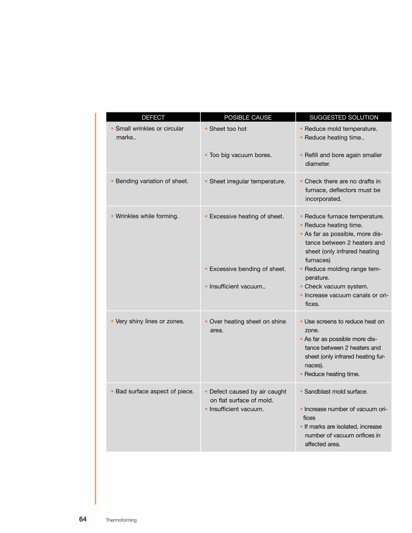
64 Thermoforming
DEFECT SUGGESTED SOLUTION
• Small wrinkles or circular marks..
• Bending variation of sheet.
• Wrinkles while forming.
• Very shiny lines or zones.
• Bad surface aspect of piece.
• Sheet too hot
• Too big vacuum bores.
• Sheet irregular temperature.
• Excessive heating of sheet.
• Excessive bending of sheet.
• Insufficient vacuum..
• Over heating sheet on shine area.
• Defect caused by air caught on flat surface of mold.
• Insufficient vacuum.
• Reduce mold temperature. • Reduce heating time..
• Refill and bore again smaller diameter.
• Check there are no drafts in furnace, deflectors must be incorporated.
• Reduce furnace temperature.• Reduce heating time. • As far as possible, more dis-
tance between 2 heaters and sheet (only infrared heating furnaces)
• Reduce molding range tem-perature.
• Check vacuum system.• Increase vacuum canals or ori-
fices.
• Use screens to reduce heat on zone.
• As far as possible more dis-tance between 2 heaters and sheet (only infrared heating fur-naces).
• Reduce heating time.
• Sandblast mold surface.
• Increase number of vacuum ori-fices
• If marks are isolated, increase number of vacuum orifices in affected area.
POSIBLE CAUSE

65 Thermoforming
DEFECT SUGGESTED SOLUTION
• Piece surface bad aspect
• Excessive distortion or shrinking after removing a piece off a mold.
• Excessive thinning of walls of a piece
• Excessive mold temperature. • IInsufficient mold tempera-
ture.. • Superficie del molde demasia-
do áspera o rugosa. • Dirty sheet.
• Piece removed too fast.
• Inadequate forming tech-nique.
• Material thickness variation.
• Uneven sheet heating. • Sheet at excessive tempera-
ture.
• Cold mold.• Sheet not firmly fastened to
frame.
• Reduce mold temperature. • Increase mold temperature.
• Soften mold surface. • Make mold of other material. • Clean sheet.
• Prolong cooling cycle. • Move the piece to a cooling
template.• Use refrigerant. • Use water spray steam to
reduce piece temperature. • use electric ventilators to cool
piece inside the mold.
• Use different forming techni-que: vacuum with return, pres-sured air and mechanical sup-port, pressured air and return with vacuum.
• Check material meets quality norms and /or complain.
• Check furnace operation. • Reduce furnace temperature.
• Reduce heating time.• Heat mold. • IIncrease closing pressured.
• Check possible sheet thick-ness variation.
POSIBLE CAUSE

66 Thermoforming
DEFECT SUGGESTED SOLUTION
• Pieces twist
• Shrinking marks on corners.
• Bubble stretches unevenly.
• In deep forming, thin cor-ners.
• Piece cooled wrongly. • Uneven wall thickness distri-
bution.
• Wrongly designed mold.
• Wrongly designed piece.• Insufficient mold temperature.
• Mold surface too smooth. • Insufficient vacuum.
• Insufficient sheet temperature.• Sheet uneven thickness.• Insufficient pressured air.
• Wrong forming technique.
• Thin sheet• Sheet unevenly heated
• Mold wrongly heated.
• Adjust cooling cycle. • Use pre-stretching mechanical
or technical support. • Sheet might be unevenly heat-
ed.• Increase vacuum orifices. • Modify mold• As far as possible, curve a little
flat areas.• Increase mold temperature.
• Sandblast mold surface. • Check vacuum system.• Add more orifices.
• Check furnace operation con-dition
• Use cooling screens (Only infrared radiation heating fur-nace.).
• Longer heating time at lower temperature.
• Incorporate an air distribution system with deflectors.
• Change forming technique.
• Increase sheet thickness. • Check furnace operation. • Use screens to change heat
distribution. • Change furnace temperature.
POSIBLE CAUSE

67 Thermoforming
DEFECT SUGGESTED SOLUTION
• Piece sticks to mechanical support.
• Piece sticks to mold.
• Corners of formed piece shatter once in use..
• Mechanical support (wood).
• Mechanical support (metal).
• Piece high temperature.
• Mold insufficient exit angle.
• Wooden mold.
• Piece wrongly designed. • Effort concentration on a
piece.
• Apply removing agent.• Cover with soft felt or flannel. • Apply removing agent. • Lower support temperature.• Cover with felt or flannel.
• Longer cooling time.• Reduce mold temperature. • Give 1° and 3° angle • Change matrix. • Apply removing agent.
• Redesign piece. • Increase mold curve radius. • Increase thermoforming tem-
perature.• Make sure piece is wholly
formed before it cools below forming temperature.
POSIBLE CAUSE

68 Thermoforming
APPENDIX
ABSORBENCYFraction of radiant energy taken by a sheet.
CAVITYDepression of a vacuum made mold, machine finished or a combination of both,.depending on the number of depressions, it may have one or several cavities.
CONDUCTIONEnergy transferred by directly touching a solid.
CONVECTIONEnergy transferred by the movement of a fluid current.
COOLING MARKSMarks caused by using wrong temperature on a plastic sheet, derived from inadequateheating.
CO-POLYMERPolymer composed of tow different kinds of monomers.
CYCLEComplete repetitive sequence in the thermoforming process, which consist in: heating,forming, cooling and removal.
DIMENSIONAL STABILITYCapacity of a piece to keep the accurate shape and dimension of the mold used.
ENTHALPYInner energy of a system.
HEAT TRANSFER COEFFICIENTEffectiveness measure of energy transported between a fluid current and a solid surface.
HOMO-POLYMER Polymer made of only one monomer
INFRAREDPart of electro-magnetic spectrum, between the range of visible light and the range ofradio waves. Radiant heating is the range at which infrared heaters are used to heat asheet. Wave length is 0.08” to 0.4”
Glossary

69 Thermoforming
MELTING TEMPERATURERange of temperature at which a crystalline polymer turns from a solid rubber-like stateinto a viscous-elastic liquid.
MOLDING TEMPERATUREA piece temperature at which it can be removed without deforming.
PRESSURED AIR SHAPINGDifference of pressure exceeding two atmospheres (30 Psi.).
RADIATIONIt is the transfer or exchange of electromagnetic energy.
REFLECTIVITYFraction of radiant energy reflected on a sheet surface.
RESINAnother name to call a polymer or plastic material.
SCRAPMaterial waste that is not part of the final piece.
TENSIONExternal charge exerted on a defined area.
THERMAL DIFFUSIVENESSTransmission index of calorific energy in a material.
TRANSMITTANCEFraction of energy that is transmitted through a sheet.
TRI-POLYMER Polymer composed of three different kinds of monomers.
VACUUM TANKTank between the vacuum pump and the mold, that allows you to apply pressure even-ly during forming.
70 Thermoforming
Plastic reinforced with glass fiber
IntroductionReinforced plastics are those thermo-plastic or thermo-fixed materials, in whose shap-ing process, some reinforcing material is used to improve their mechanic characteris-tics. This reinforcing material can be continuous or discontinuous. As examples of theformer there are fiber materials like: salwort, jute, henequen, rayon, etc., but the mostused is glass fiber.
A polyester is made by the reaction of a poly-basic acid and a polyhydric-alcohol, attemperatures over 212°F (100ºC), getting one polyester and water. Depending on thetype of acids and alcohol used and modifications performed, the following kinds ofproducts will be obtained.
Non saturated polyestersThese are lineal polyester resins obtained when dibasic acids and polyvalent alcoholsreact, and can polymerize in a cross-linking way with vinyl monomers to make ther-mofixed plastic..
Alkyd polyesters.These are the ones modified with oil, used for decorative and/or protective coverings,for example: paints, varnishes, printing inks, etc.
Plasticizing polyestersPolyesters totally saturated that are used to soften other plastics, they are also knownas polymeric plasticizers. They are used to make vinyl with or without reinforcement,for example: the one used for car upholstery, wall paper, etc.
Fibers and filmsThey are polyesters of heavy molecular weight, molecularly oriented and for which spe-cific acids and alcohol are used. Example: polyethylene, polypropylene, etc.
Polyester foam.Polyesters with a great number of hydroxyl groups and that react with interlinkedchains with isomeric acid groups, to make foams, elastomers, coverings, etc.
According to the previous classification, polyesters are a great variety of chemicalcomposites and products. However, they are generally used to name compositesdefined as non-saturated polyesters, so unless something else is suggested, thisdenomination will be adopted.
Polyester resins are used in a wide variety of applications, in different industries, forexample: forming with reinforcing materials (reinforced plastic), encapsulating, protec-
Resin, polyester
and reinforcedplastic
71 Thermoforming
tive covering, decorative objects, buttons, etc. Reinforced plastic industry is the onethat has the most polyester consumption.
Increasing demand and application of plastic reinforced items are basically due to theirproperties and features, among which, the following can be mentioned:
1) Composites are easy to handle (polyester resin is applied in liquid form).2) Easy curing and using.3) Excellent dimensional stability in the final product.4) Good dielectric properties.5) Excellent physical and mechanical properties. A reinforced plastic sheet, equivalentto three times steel thickness, has mechanical resistance to tension, weighs about halfand is more resilient.6) Rust resistant and also to a great amount of chemical agents. 7) Easy finishing (coloring, painting, machine finishing, etc.).
To obtain optimal reinforced plastic features, the reinforcing material must have thebest mechanical and chemical properties. Next, reinforcements most used are men-tioned.
Reinforcing materialsThe most important reinforcing material are:
1.- Cellulose fibers.Cellulose alpha.Cotton.Jute.Salwort.Rayon.
2.- Synthetic fibers.Polyamides (nylon).Polyester (Dacron).Polyacrylonitrile.Polyvinyl alcohol fibers.
3.- Asbestos fibers.
4.- Special fibers.Carbonate and graphite fibers.Boron and tungsten fibers.Ceramic fibers.

72 Thermoforming
5.- Reinforcing charges.
6.- Glass fibers.

73 Thermoforming
Glass fiber
In reinforced plastic industry, the material most used is glass fiber because of its fea-tures:
1.- Tension high resistant.2.- Incombustible.3.- Biologically inactive.4.- Excellent weather resistant as well as to a great deal of chemical agents.5.- Excellent dimensional stability.6.- Low thermal conductivity.
The main uses of glass fiber reinforcements are:
Roving.Mat.Woven roving.Surfacing mat.Chopped strand.
Following, processes to obtain these and their features are mentioned.
RovingRoving is one of the most used glass fiber products, and it is indispensable when rein-forced plastic items are made by sprinkling, directed filament and hot forming (pre-form manufacturing). Roving comes wound on bobbins, and it usually has 60 threads.

74 Thermoforming
MatThis is the most popular and known glass fiber product in reinforced plastic industryand it is made of fiber mono-filaments about 2”, long.
Woven rovingThis is roving strings woven at 90° angles as to their longitudinal axes. Combined withmat, it is used as secondary reinforcement, to manufacture boats and big structures.
Surfacing mat This material is made of glass fiber sections like the mat, though with less weight/unitarea. It is mainly used to improve the finishing of reinforced plastic products and toincrease their weather resistance features; since when it is put on the reinforcementmaterial, usually a mat, it does not allow the fiber to crop up and as it absorbs resin,finishing gets smoother.
Chopped strandThis glass fiber presentation is not much used, it is made by the machine that makesmat. Its size varies from 2/2" to 2" long (1.25 to 5.0 cm). It is mainly used to make itemsby methods of pre-mixing.
According to reinforcing materials classification, there is another type of products usedin the manufacture of reinforced plastics, the most important are:
Asbestos.Salwort, henequen, jute.Synthetic fibers.Ceramic fibers.Polyvinyl alcohol fibers.Special reinforcements.
To improve reinforced plastic efficiency and application, several reinforcing elementshave been developed. Their main characteristic is a high elasticity module, which con-siderably increases mechanical resistance of laminated products. This is speciallyimportant in specialized fields like aero-spatial vehicles, submarines, etc. Among thesereinforcements are:
Boron tungsten filaments.Carbonate and graphite fibers.Metallic filaments.WhiskersAdhesion promoting agents.Hybrid reinforcements.Metalized reinforcements.

75 Thermoforming
Mechanical resistance of a plastic/reinforcing composite derives from joining, gener-ally mechanically a system composites. This joint, satisfactory in most cases, mayreduce composite or product aging as well as moisture, when glass fiber systems areused to reinforce, since the fiber is hydrophilic and tends to absorb water which weak-ens or destroys plastic joints.
To prevent this, chemical composites hydrogen siliceous type are added to the inor-ganic charge, resin or reinforcing material. They provide a chemical consolidation in theinterface of the joint, improving and keeping the mechanical properties of composites,apart from improving dielectric characteristics of the system.
Manufacturing reinforced plastic molds.To make a mold, a model or original of the piece to be made is required. When thereare only specifications and blue prints, the model can be made of cast, wood, or epoxypaste, depending on how difficult the piece is and how skilled the operators are. Sometimes, the model can be made by combining polyurethane foam or polystyrene platescovered with a thin coat of cast or epoxy.
When the model is finished, roughness can be smoothed with emery cloth and thenapplying a sealer to eliminate porosity. In most of the cases it can be a nitro-celluloselacquer, which is spayed, or shellac dissolved in alcohol. To polish the model, a remov-ing agent is applied, its specific function is avoiding adherence of the resin to the mold.Removing agents can be classified in three groups:
Solutions.Generally aqueous polyvinyl-alcohol, methyl-cellulose, etc. This kind of removers mustbe applied in each molding operation.
Waxes and wax emulsionsThis agent is applied with a flannel or felt, and polished manually.
Internal removersThese agents are mixed with gel-coat. When they mix with the tooling gel-coat, remov-ing characteristics improve, making molding easy.
Once the removing agent has been chosen, the mold is coated with a resin prepara-tion known as gel-coat or finishing coat.
Gel-coatIt is made of a resin that provides a film whose characteristics are:
1.-Uniform surface.2.-Avoiding that reinforcing material crops up.3.-Improving weather resistant properties.

76 Thermoforming
Some times, a glass fiber mat should be put to reinforce gel-coat, getting a resin richcoat and avoiding that the reinforcing material crops up. Gel-coat is usually sprayed,but it can also be applied with hair brushes. In that case, accelerator/catalyst quanti-ties should be less than for immersion. Finishing film thickness depends on the use andcharacteristics of the piece to be made and it can be measured with a calibrator ofhumid film.
Manual finishing processIt is often used since it does not require any special equipment. Its process is:
A mold prepared with removing agents (wax, removing film or both) is coated with afinishing product using a soft brush or spraying equipment, thickness varies depend-ing on the use of the piece and the supplier’s specifications. Once the gel-coat thick-ness is determined and it has been cured, the glass fiber mat is placed. Next, using abrush and with vertical movements, a resin of styrene monomers or methyl methacry-late, or both, is applied to the mold, as well as the accelerator, whiskers and/or toxi-tropic agents, heat concentrator, catalyst, etc.
Later, and before the resin jells rolling is done, with a plastic or metal 0.36” to 1” (9.0to 25mm.) diameter and 2” to 8” (5 to 20 cm.) long roller generally grooved, dependingon the case.
Rolling the roller in several directions pressing evenly helps to eliminate air caught inthe resin and reinforcing material, as well as to obtain good adhesion with the gel-coat.Finishing and rolling should be done by sections no bigger than 1m2 when a piece is big.
77 Thermoforming
Often, commercial measurements of mat and woven roving (which are always appliedwith this procedure) are not enough to cover the whole mold; therefore, they have tobe joined by sections. Overlapping them 5cm is suggested. The resin to join themshould have the least accelerator and catalyst to avoid problems created by materialcontractions which derived from a bigger amount of resin, that reduces curing time andincreases exo-thermal temperature.
Some times, one or more woven roving layers have to be used as reinforcement. Theymust be put between the 2 mat sections, or even better, as a final layer and neverdirectly with the gel-coat, because if the finishing coat is not properly applied, thewoven roving will be visible, which will give the product a bad aspect.
The brushes and rollers have to be washed intermittently with a solvent like acetone,ethyl acetone, methyl ethyl acetone, etc., since as the resin cures it hardens and theymay get damaged. Most of the time it is enough to put them in a container with a sol-vent or a monomer mixture.
Reinforced plastic machine finishing.Reinforced plastic product manufacturing, often includes machine finishing or adjust-ing, operations that are not highly specialized, but must be done carefully to get goodresults. Among machine finishing operations are: cutting, perforating, joining, etc. Themost important are detailed next
Cutting on the mold.It is also known as trimming and it is cutting the material (glass fiber and resin) that sur-passes the mold or piece made. This is done with steel blades along the edge of the moldwhen the resin is jelled and has not been totally cured. In the case of products manufac-tured with pressure or temperature, cutting must be done immediately after removing thepiece; otherwise, it becomes harder to do so.
Cutting with equipment.It is performed on totally finished products. Abrasive products are recommended, sincemetallic disks are not as fast, accurate, and ergonomic as the ones suggested. Watershould be used as cutting takes place; since water acts as refrigerant and lubricanthelping to eliminate reinforced plastic dust and the cut is cleaner.
Reinforced plastic jointsOften, 2 or more sections have to be joined to get a final piece; The systems commonlyused are

78 Thermoforming
Joining with adhesivesAlthough this kind of joining can be done in 2 ways, on the edges or overlapping, thelatter is the most used. Because contact surface is bigger. The adhesives most usedare: polyester resin (modified with flexible resin) or epoxy resin that provides excellentadhesion. Adhesive material can be put directly on the plastic surface, though apply-ing it on a layer of reinforcing material is suggested, placing the layer between the sur-face to be joined, and pressing next, to obtain uniformity in the joint.
Rivets.Rivets are not often used in this industry, but if needed, aluminum or bronze ones arerecommended. They must not be bigger than 4.5mm (3/16") diameter. The minimumdistance from the edge is three times their diameter. Besides, flat washers should beused to reduce the rivet tendency to penetrate laminated.
Using screwsScrews are the most commonly used to join reinforced plastic pieces, excepting adhe-sives. The use of setscrews is not advisable. Using a screw and nut has the advantagethat they are easy to place, are adjustable and available. To get the most efficiency, thefollowing rules must be followed:
• Distance between the center of the screw and the edge of a laminated must be min-imum three times the screw diameter.
• Separation between the center of each screw must be 2.5 times perforation diameter.
• Flat washers should be used on both sides of laminated, thus, charge and mechan-ical efforts are uniformly distributed
• Perforations must be perpendicular to reinforcing layer, and the screws must adjust perfectly in. (Both screw and perforation diameter must be the same)..
• Screws allow using adhesives, which will provide a better quality and more resistant joint.

Table: unit conversions.
Specific gravit: 1 = 62.4
Specific heat: 1 = 1
Heat fusion: 1 =12 = 0.00413 = 0.0173
Thermal conductivity: 1 = 1.80
79 Thermoforming
gcm3
Btulb° F
calg° C
inln° F
cmcm° C
Btu ftsq hr° F
Btu insq ft hr° F
cal cmcm2 sec °C
W cmcm2 °C
lbcu ft

80 Thermoforming
ºF50 55 60 65 70 75 80 85 90 95 100 105 110 115 120 125 130 135 140 145 150 155 160 165 170 175 180 185 190 195 200 205 210 215 220 225 230 235 240 245 250 255 260 265 270
ºC 10
12.8 15.6 18.3 21.1 23.9 26.7 29.4 32.2 35.0 37.8 40.6 43.3 46.1 48.9 51.7 54.4 57.2 60.0 62.8 65.6 68.3 71.1 73.9 76.7 79.4 82.2 85.0 87.8 90.6 93.3 96.1 98.9
101.7 104.4 107.2 110.0 112.8 115.6 118.3 121.1 123.9 126.7 129.4 132.2
ºF 275 280 285 290 295 300 305 310 315 320 325 330 335 340 345 350 355 360 365 370 375 380 385 390 395 400 405 410 415 420 425 430 435 440 445 450 455 460 465 470 475 480 485 490 495 500
ºC135
137.8 140.6 143.3 146.1 148.9 151.7 154.4 157.2 160.0162.8 165.6 168.3 171.1 173.9 176.7 179.4 182.2 185.0 187.8 190.6 193.3 196.1 198.9 201.7 204.4 207.2 210.0 212.8 215.6 218.3 221.1 223.9 226.7 229.4 232.2 235.0 237.8 240.6 243.3 246.1 248.9 251.7 254.4 257.2 260.0
Temperature scale conversion formulas.ºF = °C x l.8 + 32 ºC = ºF - 32/1.8
Table: temperature scale conversion.

81 Thermoforming
IMPORTANT: CHEMCAST is not legally liable for the recommendations or information given in this manual,which are based on information we consider to be true, we offer it bona fide, but we do not guarantee it, sincetransformation conditions and use of products are beyond our control.