Thermo-active Ground-Source Structures for Heating … · heating: energy diaphragm walls and piled...
10
Procedia Engineering 57 (2013) 9 – 18 1877-7058 © 2013 The Authors. Published by Elsevier Ltd. Open access under CC BY-NC-ND license. Selection and peer-review under responsibility of the Vilnius Gediminas Technical University doi:10.1016/j.proeng.2013.04.005 11th International Conference on Modern Building Materials, Structures and Techniques, MBMST 2013 Thermo-Active Ground-Source Structures for Heating and Cooling Heinz Brandl* Vienna University of Technology, Karlsplatz 13/220-2,1040 Vienna, Austria Abstract Energy foundations and other thermo-active ground structures, energy wells, and pavement or bridge deck heating / cooling represent an innovative technology that contributes to environmental protection and provides substantial long-term cost savings and minimized maintenance. The paper focuses on earth-contact concrete elements that are already required for structural reasons, but which simultaneously work as heat exchangers. Absorber pipes filled with a heat carrier fluid are installed within conventional structural elements (piles, barrettes, diaphragm walls, basement slabs or walls, tunnel linings), forming the primary circuit of a geothermal energy system. The natural ground temperature is used as a heat source in winter and for cooling in summer. Hence no additional elements have to be installed below surface. The primary circuit is then connected via a heat pump to a secondary circuit within the building. Benefits of energy foundations are also listed in this paper. Keywords: energy foundation; energy pile; thermo-active ground-source structure; geothermal geotechnics. 1. Introduction During the past 20 years the technology of energy foundations and other thermo-active ground-source systems has developed extremely well, and Austria has still a pioneering role as indicated in Figure 1, showing the increase of energy piles between 1984 and 2010. Since the year 2005 more than 7,000 energy piles have been installed per year resulting in a total number of presently nearly 100,000 energy piles, ranging from small diameter driven piles to large diameter bored piles (Fig. 2). Moreover, “Energy diaphragm walls” (slurry trench walls) have become a frequently used alternative to energy piles in Austria. Numerous buildings with deep basements and metro lines, e.g. all new stations of the Vienna Metro have “Energy diaphragm walls”. They dominate especially in areas with a high groundwater level, whereby concepts combined with energy piles have proved suitable in many cases, see Figs 3, 4. A seasonal operation with an energy balance of heating and cooling has proved to be most economical and environmentally friendly. This would also correspond to changing energy consumption of houses since the 1970s. Especially since the year 2000 the required energy for heating has decreased significantly, but on the other hand the energy for cooling is increasing, mainly due to large glass facades and permanently closed windows of modern architecture. Comparative investigations have disclosed that for a life-time of more than 50 years the operation costs of houses (especially for residential and office buildings, shopping centres) are significantly higher than the construction costs. Therefore, optimized energy concepts are of greatest importance, also with regard to environmental aspects. * Corresponding author. Tel.: +43 1 58801 22101; fax: +43 1 58801 22198. E-mail address: [email protected] Available online at www.sciencedirect.com © 2013 The Authors. Published by Elsevier Ltd. Open access under CC BY-NC-ND license. Selection and peer-review under responsibility of the Vilnius Gediminas Technical University
Transcript of Thermo-active Ground-Source Structures for Heating … · heating: energy diaphragm walls and piled...

Procedia Engineering 57 ( 2013 ) 9 – 18
1877-7058 © 2013 The Authors. Published by Elsevier Ltd. Open access under CC BY-NC-ND license.
Selection and peer-review under responsibility of the Vilnius Gediminas Technical Universitydoi: 10.1016/j.proeng.2013.04.005
11th International Conference on Modern Building Materials, Structures and Techniques, MBMST 2013
Thermo-Active Ground-Source Structures for Heating and Cooling
Heinz Brandl*
Vienna University of Technology, Karlsplatz 13/220-2,1040 Vienna, Austria
Abstract
Energy foundations and other thermo-active ground structures, energy wells, and pavement or bridge deck heating / cooling represent an
innovative technology that contributes to environmental protection and provides substantial long-term cost savings and minimized
maintenance. The paper focuses on earth-contact concrete elements that are already required for structural reasons, but which
simultaneously work as heat exchangers. Absorber pipes filled with a heat carrier fluid are installed within conventional structural
elements (piles, barrettes, diaphragm walls, basement slabs or walls, tunnel linings), forming the primary circuit of a geothermal energy
system. The natural ground temperature is used as a heat source in winter and for cooling in summer. Hence no additional elements have
to be installed below surface. The primary circuit is then connected via a heat pump to a secondary circuit within the building. Benefits of
energy foundations are also listed in this paper.
© 2013 The Authors. Published by Elsevier Ltd.
Selection and peer-review under responsibility of the Vilnius Gediminas Technical University.
Keywords: energy foundation; energy pile; thermo-active ground-source structure; geothermal geotechnics.
1. Introduction
During the past 20 years the technology of energy foundations and other thermo-active ground-source systems has
developed extremely well, and Austria has still a pioneering role as indicated in Figure 1, showing the increase of energy
piles between 1984 and 2010. Since the year 2005 more than 7,000 energy piles have been installed per year resulting in a
total number of presently nearly 100,000 energy piles, ranging from small diameter driven piles to large diameter bored
piles (Fig. 2). Moreover, “Energy diaphragm walls” (slurry trench walls) have become a frequently used alternative to
energy piles in Austria. Numerous buildings with deep basements and metro lines, e.g. all new stations of the Vienna Metro
have “Energy diaphragm walls”. They dominate especially in areas with a high groundwater level, whereby concepts
combined with energy piles have proved suitable in many cases, see Figs 3, 4.
A seasonal operation with an energy balance of heating and cooling has proved to be most economical and
environmentally friendly. This would also correspond to changing energy consumption of houses since the 1970s.
Especially since the year 2000 the required energy for heating has decreased significantly, but on the other hand the energy
for cooling is increasing, mainly due to large glass facades and permanently closed windows of modern architecture.
Comparative investigations have disclosed that for a life-time of more than 50 years the operation costs of houses
(especially for residential and office buildings, shopping centres) are significantly higher than the construction costs.
Therefore, optimized energy concepts are of greatest importance, also with regard to environmental aspects.
* Corresponding author. Tel.: +43 1 58801 22101; fax: +43 1 58801 22198.
E-mail address: [email protected]
Available online at www.sciencedirect.com
© 2013 The Authors. Published by Elsevier Ltd. Open access under CC BY-NC-ND license.
Selection and peer-review under responsibility of the Vilnius Gediminas Technical University

10 Heinz Brandl / Procedia Engineering 57 ( 2013 ) 9 – 18
Fig. 1. Number of energy piles installed in Austria; since 2005 more than 6000 energy piles per year
Fig. 2. Absorber pipes fitted to the reinforcement cage of a large-diameter
bored energy pile
Fig. 3. Some examples of thermo-active ground-source systems for heating
and cooling of buildings
Fig. 4. Cross section through an Arts Centre with geothermal cooling and
heating: energy diaphragm walls and piled raft (energy piles)

11 Heinz Brandl / Procedia Engineering 57 ( 2013 ) 9 – 18
2. Examples of application
Subsurface geothermal resources can be used widely for heating and/or cooling all sorts of buildings and traffic areas by
utilizing structural elements for energy extraction or storing:
• Piles, barrettes, and diaphragm walls as foundation elements or sub-surface side walls;
• Shallow foundations;
• Retaining walls;
• Embankments;
• Tunnel linings (especially near to the portals).
Special applications are:
• Heating/cooling of multi-purpose buildings;
• Cooling/heating of Metro stations and service rooms;
• Heating/cooling of road pavements, parking places;
• Heating of airport runways;
• Heating/cooling of bridge decks. In countries with cold winters and hot summers the heating and cooling of bridge decks
provides numerous environmental, technical, and economical advantages: No gritting and de-icing salting in winter;
reducing rutting of asphalt pavements in summer; reducing temperature constraints, thus increasing the service lifetime;
reducing maintenance costs;
• “Energy tunnels” for heating/cooling of buildings near to the tunnel portals. They may be excavated as closed systems,
e.g. by the NATM or by the cut and cover method;
• Closed systems use the tunnel support and lining as energy absorbers. These may be anchors, rock/soil nails,
geosynthetics, and the secondary concrete lining;
• “Energy wells” for heating/cooling of buildings near groundwater extraction wells (e.g. for temporary or permanent
groundwater lowering);
• The Austrian Railway Authorities plan to use geothermal energy from thermo-active foundations, retaining walls and
tunnels for heating (and cooling) railway stations, platforms, pedestrian ramps and staircases along the new high-speed
railway lines;
• Heating of turf in sport stadia is another possibility to use geothermal energy. This is increasingly performed in countries
with long and cold winters but is rather expensive due to a low efficiency.
Fig. 5. Scheme of a geothermal energy plant with energy piles and an energy flux for COP = 4 of the heat
pump.COP = coefficient of performance defining the heat pump efficiency
3. Thermo-active circuits for energy foundations
A thermo-active system consists of the primary circuit below ground and the secondary circuit in the building (Fig. 5).
12 Heinz Brandl / Procedia Engineering 57 ( 2013 ) 9 – 18
The primary circuit contains closed pipework in earth-contact concrete elements (piles, barrettes, diaphragm walls,
columns, base slabs, and wells) through which a heat carrier fluid is pumped that exchanges energy from the building with
the ground. The heat carrier fluid is a heat transfer medium of either water, water with antifreeze (glycol) or a saline
solution. Glycol–water mixtures have proved most suitable, containing also additives to prevent corrosion in the header
block, valves, the heat pump, etc. Once cast, the pipings within the underground-contact concrete elements are individually
joined to a header and manifold block. They are joined by connecting pipes which, in the case of energy foundations, are
normally laid within the blinding beneath the base slab. The secondary circuit is a closed fluid-based building heating or
cooling network (secondary pipework) embedded in the floors and walls of the structure or in bridge decks, road structures,
platforms, etc.
Commonly, primary and secondary circuits are connected via a heat pump that increases the temperature level, typically
from 10–15 °C to a level between 25 °C and 35 °C, see Fig. 5.
All that is required for this process is a low application of electrical energy for raising the originally non-usable heat
resources to a higher, usable temperature. The principle of a heat pump is similar to that of a reverse refrigerator. In the case
of the heat pump, however, both the heat absorption in the evaporator and the heat emission in the condenser occur at a
higher temperature, whereby the heating and not the cooling effect is utilised.
The coefficient of performance, COP, of a heat pump is a device parameter and defined by
[ ]
[ ]energy output after heating pump kWCOP
energy input for operation kW=
(1)
The value of COP = 4 means that from one portion of electrical energy and three portions of environmental energy from
the ground four portions of usable energy are derived (Fig. 5).
The efficiency of a heat pump is strongly influenced by the difference between extracted and actually used temperature.
A high user temperature (inflow temperature to the heating system of the secondary circuit) and a low extraction
temperature (due to insufficient return-flow temperature) in the heat exchanger (primary circuit) reduce its efficiency. For
economic reasons a value of COP ≥ 4 should be achieved. Therefore, the usable temperature in the secondary circuit should
not exceed 35–45°C, and the extraction temperature in the absorber pipes should not fall below 0–5°C. Consequently, this
technology tends to be limited to low temperature heating (and cooling).
The seasonal performance factor (SPF) of a thermo-active system with a heat pump is the ratio of the usable energy
output of the system to the energy input required to obtain it. Therefore SPF includes not only the heat pump but also other
energy-consuming elements (e.g. circulation pumps). At present, values of SPF = 3.8–4.3 are achieved with standard
electric heat pumps. Special devices with direct vaporisation increase SPF by 10–15%.
[ ]
[ ]usable energy output of the energy system kWhSPF
energy input of the energy system kWh=
(2)
If only heating or only cooling is performed, high-permeability ground and groundwater with a high hydraulic gradient
are of advantage. However, the most economical and environmentally friendly is a seasonal operation with an energy
balance throughout the year, hence heating in winter (i.e. heat extraction from the ground) and cooling in summer (i.e. heat
sinking/recharging into the ground). In this case low-permeability ground and groundwater with only low hydraulic
gradients are favourable.
There is no limitation to the depth of piles as far as the installation of energy absorber systems is concerned. The energy
potential increases with depth: hence deeper ground-sourced energy systems are advantageous. The economically minimum
length of piles, barrettes or diaphragm wall panels is about 6 m. Energy wells should reach deeper, because they have a
lower heat transfer capacity.
4. Design aspects of energy foundations
Early ecological energy planning for building can often prevent costly refurbishment and renovation in the future. High-
quality energy design involves not only heating and cooling (rooms, water) but also lighting, and it requires a multi-
objective optimisation.
An optimized energetic-thermal design should also consider the seasonal heat loss from (un-) insulated slab - on ground
floors or basement walls. Far more energy and costs are expended in running an inefficiently laid out building than in

13 Heinz Brandl / Procedia Engineering 57 ( 2013 ) 9 – 18
constructing an efficient one. A proper design should consider the efficiency of the overall building process, including the
sustainability of all elements.
For general feasibility studies and pre-design of energy foundations the following assumptions can be made regarding the
energy volume that can be extracted from thermo-active energy foundations:
• Pile foundations with piles D = 0.3 to 0.5 m: 40 to 60 W/m run;
• Pile foundations with piles D = > 0.6 m: 35 W/m² earth-contact area;
• Diaphragm walls, pile walls (fully embedding the soil): 30 W/m² earth-contact area;
• Base slabs: 10 to 30 W/m².
Dry soil makes deeper piles and a larger area of the heat exchanger necessary. Moreover, a seasonal energy balance is
required.
The heat that can be extracted from or fed into / stored in the ground depends on the maximum possible heat flux density
in the absorber pipe system. There, the heat transport occurs by forced convection of the fluid (usually antifreeze – water
mixture). In order to optimise the absorber pipe system the following parameters have to be considered:
• Diameter and length of pipes;
• Properties of pipe wall (roughness);
• Heat conductivity, specific heat capacity, density and viscosity of fluid circulating in absorber pipes;
• Flow velocity and flow conditions (laminar-turbulent) within absorber pipes.
where
Q� = heat flux [W] c = specific heat capacity [Ws/(kgK)]
q� = heat flux density [W/m²] m� = mass flow [kg/s]
C = circumference [m] T = temperature [°C]
Pile
� = pile length [m] PHP = electrical power heat pump [W]
LPipe = length absorber pipe [m] ηHP = efficiency factor of heat pump [-]
uPipes = quantity of absorber pipes [units] εHP = coefficient of performance for heat pump [-]
α = heat transfer coefficient [W/(m²K)] εCarnot = coefficient of performance of Carnot process
Fig. 6. Scheme of heat flux balance for heating in an energy pile plant

14 Heinz Brandl / Procedia Engineering 57 ( 2013 ) 9 – 18
Figure 6 gives a schematic overview of the heat transport within a thermo-active system consisting of energy piles. It
illustrates that the heat flux primQ� transported by heat carrier fluid in the primary circuit is given by the specific heat
capacity cprim, the mass flow primm� and the temperature difference ΔTprim.
Complex ground properties and pile groups require numerical modelling of the geothermal heating/cooling system.
Figure 7 shows for example the daily mean temperatures in Vienna for the year 2001. Such data are needed to design a
heating–cooling system whereby it is assumed that heating typically starts at external temperatures lower than 12 °C. This
provides the heating period for the unsteady numerical models. The seasonal course of the air temperature is simulated by a
sinusoidal curve according to the following equation
,
2cos ( )GS m out out tT T T t
P
π⎡ ⎤= + Δ − ε⎢ ⎥
⎣ ⎦ (3)
where TGS is the ground surface temperature, t is time, Tm,out is the average yearly temperature, ΔTout is the temperature
amplitude, __
P is the duration period, and εt is the phase displacement.
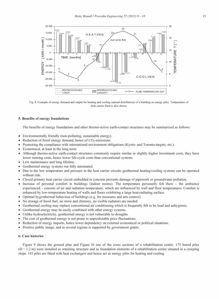
In the end, the monthly heating and cooling demands have to be compared with the available output, as indicated in
Fig. 8. Moreover, the seasonal course of the absorber fluid temperature (heat carrier fluid temperature) should be predicted.
Usually, a numerical simulation of the geothermal system is recommended for buildings with a heating and cooling
demand of more than 50 kW. This rough value decreases to about 20 kW for buildings where rooms have to be cooled
throughout the year. Geometric simplification may lead to significant errors in heat calculation. Therefore three-dimensional
analyses should be conducted. The simulation should comprise the expected inflow and outflow temperatures at the energy
foundations and the temperature distribution in the ground. Numerical models and computer programs should be reliably
calibrated, that is on the basis of long-term measurements and experience from other sites, and on physical plausibility.
Otherwise wrong results may be gained, even from well-known suppliers. Experience has shown that the results are very
sensitive to even small changes in the finite element mesh. Consequently, the importance of numerical simulations lies
rather in parametric studies (to investigate the influence of specific parameters) than in gaining ‘exact’ quantitative results.
Calculation of the temperature distribution in the ground due to energy foundations or energy wells is increasingly being
demanded by local authorities for environmental risk assessment. This refers mainly to possible influences on adjacent
ground properties and on the groundwater by the long-term operation of thermo-active deep foundations.
Monitoring of thermo-active ground-sourced systems is essential for an optimised long-term operation, and to enable
sophisticated design of future projects.
Proper geothermal energy utilization requires an interdisciplinary design, especially in the case of houses. Geotechnical
engineer, architect, building equipment (sanitation) designer and installer, heating engineer and specialized plumber should
cooperate as early as possible to create the most economical energy system. However, the tender for construction should
clearly specify individual performances on the site. It has proved suitable to entrust a geothermally experienced plumber
with all details of the primary and secondary circuits, beginning with the mounting of the absorber pipe systems in the
foundation elements.
-15
-10
-5
0
5
10
15
20
25
30
01.01.
31.01.
02.03.
01.04.
02.05.
01.06.
02.07.
01.08.
01.09.
01.10.
01.11.
01.12.
Mean
daily o
utd
oo
r te
mp
era
ture
[°C
]
Vienna 2001 (measured)
sinusoidal curve
annual mean Amplitude:11°
Start of
simulation
Amplitude:11°
Time
temperature:11°
Fig. 7. Mean daily outdoor temperatures in Vienna 2001, with idealized sinusoidal curve for numerical calculations
15 Heinz Brandl / Procedia Engineering 57 ( 2013 ) 9 – 18
Fig. 8. Example of energy demand and output for heating and cooling (annual distribution) of a building on energy piles. Temperature of
heat carrier fluid is also shown
5. Benefits of energy foundations
The benefits of energy foundations and other thermo-active earth-contact structures may be summarized as follows:
• Environmentally friendly (non-polluting, sustainable energy).
• Reduction of fossil energy demand, hence of CO2-emissions.
• Promoting the compliance with international environment obligations (Kyoto- and Toronto-targets, etc.).
• Economical, at least in the long-term.
• Although thermo-active earth-contact structures commonly require similar or slightly higher investment costs, they have
lower running costs, hence lower life-cycle costs than conventional systems.
• Low maintenance and long lifetime.
• Geothermal energy systems run fully automated.
• Due to the low temperature and pressure in the heat carrier circuits geothermal heating/cooling systems can be operated
without risk.
• Closed primary heat carrier circuit embedded in concrete prevents damage of pipework or groundwater pollution.
• Increase of personal comfort in buildings (indoor rooms). The temperature personally felt there – the ambience
experienced – consists of air and radiation temperature, which are influenced by wall and floor temperatures. Comfort is
enhanced by low-temperature heating of walls and floors exhibiting a large heat-radiating surface.
• Optimal hygrothermal behaviour of buildings (e.g. for museums and arts centres).
• No storage of fossil fuel, no stove and chimney, no visible radiators are needed.
• Geothermal cooling may replace conventional air conditioning which is frequently felt to be loud and unhygienic.
• Geothermal energy may be easily combined with other energy systems.
• Unlike hydroelectricity, geothermal energy is not vulnerable to droughts.
• The cost of geothermal energy is not prone to unpredictable price fluctuations.
• Reduction of energy imports, hence lower dependency on external economical or political situations.
• Positive public image, and in several regions is supported by government grants.
6. Case histories
Figure 9 shows the ground plan and Figure 10 one of the cross sections of a rehabilitation centre. 175 bored piles
(D = 1.2 m) were installed as retaining structure and as foundation elements of a rehabilitation centre situated in a creeping
slope. 143 piles are fitted with heat exchangers and hence act as energy piles for heating and cooling.

16 Heinz Brandl / Procedia Engineering 57 ( 2013 ) 9 – 18
Fig. 9. Ground plan of the rehabilitation centre Bad Schallerbach/Austria with energy piles and energy transfer system
Fig. 10. Partial view of the anchored energy pile wall on the uphill side of the building being part of the heating/cooling system
(Central cross section in Fig. 9)
Since autumn 1997 the energy piles have been under full operation without any problem. Long-term monitoring revealed
typical seasonal temperature fluctuations with relatively large amplitudes of maximum and minimum pile temperatures in
summer and winter – as intended for this pilot project. Consequently, the pile temperatures in the subsequent winter were
somewhat higher than in the quasi-steady state before.
In Figure 11 some temperature curves are selected as examples of heating and cooling periods in relevant years.
Immediately after commencing continuous operation of the geothermal system started (with excessive heating); the year
2003 had a very high cooling demand, and there was quasi-steady state in the year 2004/2005.
A multi-purpose hall with a capacity of 8,000 persons was designed for exhibitions, fairs, and as a sports hall, especially
as an ice rink. The latter required intensive cooling and temporary heating. The complex energy management could be
solved with energy piles, because piles were already needed for a deep foundation of the structure resting on weak clays
(Fig.12). The deep foundation comprises 320 cast in situ concrete piles (bored piles, D = 0.5 m) of 18 m length. The piles
contain in total about 65 km absorber pipes (HDPE; d = 25 mm). This cooling/heating system provides an annual saving of
85,000 m³ of natural gas which is equivalent to an environmental relief of 73 tons CO2.
In the same region a 43 m high Spa Hotel with geothermal heating and cooling was built. The core of the Spa centre
comprises four floors with 6,500 m² of spa and fitness zones, and a 2,000 m² bath and sauna world. The energy foundation
consists of 357 auger piles, 30 m long and includes 69,000 m of plastic pipes. Groundwater temperature is constant about
12°C. Primary and secondary energy circuits are connected by a 400 kW heat pump. In winter 1.6 GWh are extracted from

17 Heinz Brandl / Procedia Engineering 57 ( 2013 ) 9 – 18
the ground, corresponding to the energy demand of about 160 modern one-family houses. About the same heat volume is
then sunk back into the ground when cooling the building in summer.
Fig. 11. Temperature within energy pile against pile depth; some data from long-term operation illustrating the seasonal fluctuation since the
construction phase
In 2007 Austria’s first low-energy shopping centre was opened using its pile foundation for heating and cooling. 650
piles of in total 800 bored piles (diameter D = 0.9 m, some piles with D = 1.2 m; depth = 50 m) are equipped with absorber
pipes. The subsoil consists of 3 to 5 m sandy gravel underlain by soft sandy-clayey silt (banded) down to 40 m, and finally
sand to gravel. The groundwater level lies about 3 m below surface. Thus a significant magnitude of conventional energy
can be saved: 4.1 GWh/a of fossil fuel, 61 MWh/a of electrical energy. Furthermore, the energy piles instead of
conventional heating/cooling systems save nearly 550 tons of CO2. Temporary surplus of geothermal energy is fed into the
public district energy supply line.
Fig. 12. Energy piles for heating and cooling a multi-purpose hall
7. Promotion of geothermal energy utilisation
An early ecological energy planning for buildings can in many cases prevent costly refurbishment and renovation in the
future. High-quality energy design involves not only heating and cooling (rooms, water) but also lighting.
Building biology (including building ecology) gains increasing importance in the fight against global warming, depletion
of the ozone layer and exploitation of material resources. Building biology has become (or should become!) a multi-
disciplinary science combining architecture, civil and geotechnical engineering, physics and chemistry, installation
engineering, medicine and related sciences. It considers not only interactions of buildings and human health, but also energy
concepts, the life cycle of building materials, sustainability, etc.
Geothermal geotechnics offers a promising alternative to conventional heating/cooling systems, providing solutions to
the challenges of today's energy policies.
The targets for renewable energy and for energy buildings can be reached generally only by political measures:

18 Heinz Brandl / Procedia Engineering 57 ( 2013 ) 9 – 18
• High taxes on fossil fuels are the most important prerequisite for energy saving and promotion of renewable energy
sources.
• In order to promote the installation of thermo-active systems or/and other heating-cooling systems based on renewable
energy, the economic incentives for private investors, house owners, companies, but also for public administrators to
invest in renewable energy systems should be improved in many countries. A strong support by European Union policy
is necessary.
• Legislation.
• Public grants.
8. Conclusions
Nearly 30 years of experience with energy foundations (especially piles) has disclosed that such environmentally friendly
systems for heating and cooling of buildings have significant advantages over conventional technologies (fossil fuels etc.)
and enable sustainable and clean energy consumption. Local climate and ground properties, technological level, the specific
use of a building, seasonal fluctuations, environmental conditions and actual energy prices are the main influence
parameters of an optimized integral design.
Energy systems based on earth-contact structural elements (energy piles, energy diaphragm walls, etc.) have a double
function, and they work most efficiently if the thermo-active elements are in contact with groundwater. Nevertheless, a
sufficient seasonal performance factor of the system is achievable even without groundwater, especially for seasonal
operation, i.e. heating in winter and cooling in summer. Energy balance is the ideal form of heating/cooling. Moreover, the
smaller the temperature difference between ground source energy and used energy, the higher is the seasonal performance
factor, hence the efficiency of the thermo-active system. Usually, a temperature difference of only ΔT = 2 °C between
absorber fluid inflow and return flow from the primary circuit is sufficient for an economical operation of the energy
system. Consequently, such geothermal systems represent low-temperature systems. Experience has shown, that the
electricity required for operating the entire system commonly varies between 20 to 30% of the total energy output. If no heat
pump is necessary (e.g. for free cooling) this value drops to 1 to 3% for merely operating a circulation pump.
Despite overlapping integral design aspects there should be always a clear interface between energy foundations and
building (household etc.) regarding responsibility of construction, quality control and assurance. It has proven suitable to
consider this already in the tender design.
Proper operation of thermo-active foundation systems does not affect the load capacity of piles or diaphragm walls
during geothermal cycles (as already stated in Brandl, 1998). Hence, temperature-induced settlement or heave of buildings
with such energy foundations is negligible in relation to displacements caused by static loads.
Commonly, the groundwater temperature is changed by more than ±1°C only within a distance of less than 5 to 10 m to
the earth-contact structural elements. These values could be found even for rather large thermo-active ground structures.
The drop out rate of properly installed energy piles is negligible and occurs practically only during construction. In
Austria the failure rate usually is less than 2% of the required usable energy output of the entire energy system. If it is more,
the construction firms have to pay for reduced quality. However, for safety reasons the energy foundations are commonly
designed as if an energy loss of 10% might occur. This over-design covers failures during the construction period that
cannot be repaired and possible long-term failures or losses in the primary and secondary circuit of the energy system.
Long-term failures within energy piles can be excluded if they are operated properly. Once, energy piles have passed
positively the acceptance tests, no long-term failures could be observed until now.
Proper geothermal energy utilization requires an inter-disciplinary design, especially in the case of houses. The
geotechnical engineer, structural engineer, architect, building services designer and installer, heating engineer and
specialized plumber should cooperate as early as possible to create a most economical energy system. In the first phase of
operation precise adjustment is recommended to optimize the performance of the engineering system. Furthermore, some
operation rules have to be considered (Brandl, 1998, 2006).
References
[1] Brandl, H., 1998. Energy piles and diaphragm walls for heat transfer from and into ground, 3rd International Geotechnical Seminar, Deep Foundations
and Auger Piles (BAP III). University of Ghent. W. F. Van Impe (Ed.). Proc.: A.A. Balkema, Rotterdam, pp. 37-60.
[2] Brandl, H., 2006. Energy foundations and other thermo-active ground structures. (Rankine-Lecture). Géotechnique, Vol. LVI 2, pp. 81-122.
[3] Markiewicz, R., 2004. Numerische und experimentelle Untersuchungen zur Nutzung von geothermischer Energie mittels erdberührter Bauteile und
Neuentwicklungen für den Tunnelbau. Doctoral Thesis. Institute for Soil Mechanics and Geotechnical Engineering, Vienna University of Technology.