THERMALANALYSIS OF CURTAIN WALL SYSTEMS · NFRC 100-2014 vs ISO 12631 • Both refer to ISO 15099...
59
Transcript of THERMALANALYSIS OF CURTAIN WALL SYSTEMS · NFRC 100-2014 vs ISO 12631 • Both refer to ISO 15099...


THERMAL ANALYSIS OF CURTAIN WALL
SYSTEMS – A PARAMETRIC STUDY
Prof. Nathan Van Den Bossche, Stephanie Van Goethem, Dr. Wahid Maref
DEPARTMENT OF ARCHITECTURE AND URBAN PLANNING
RESEARCH GROUP BUILDING PHYSICS AND CONSTRUCTION

- CONTEXT
- SIMULATION METHOD
- MODEL
- 10 PARAMETERS
- CONCLUSIONS
3

CONTEXT
4
• Windows and curtain walls: high U-values
• Calculation method well defined
• Software: available
• Industry: more ambition than knowledge
• No design guidelines in literature
GOAL
• Design guidelines

CONTEXT
5
Aluminum
Vinyl
Wood

CONTEXT
6
Aluminum
Vinyl
Wood

CONTEXT
7
Aluminum
Vinyl
Wood

- CONTEXT
- SIMULATION METHOD
- MODEL
- 10 PARAMETERS
- CONCLUSIONS
8

SIMULATION METHOD
9
NFRC 100-2014
• Refers to ISO 15099 and ISO 10077-2
• Boundary conditions: Tin 21°C, Tout -18°C, wind speed 5.5m/s
• Indoor convective heat transfer coefficient is based on center-of-panel IGU surface temperature
• A cross-section should include at least 150mm of glazing section
• Correlation for convective heat transfer coefficient?
• Specific guidelines for curtain wall systems?
Therm 6.3 / Window 6.3 NFRC • Screws: section at thermal bridge
• Adopt a surface area based thermal conductivity
SIMULATION METHOD
10
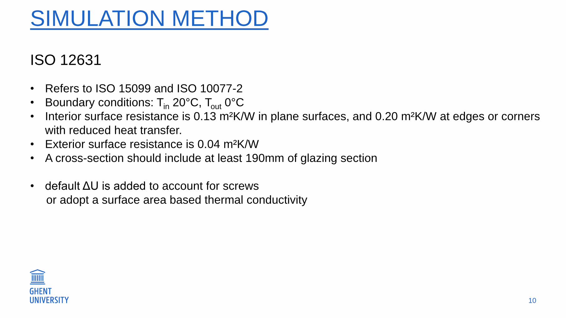
ISO 12631
• Refers to ISO 15099 and ISO 10077-2
• Boundary conditions: Tin 20°C, Tout 0°C
• Interior surface resistance is 0.13 m²K/W in plane surfaces, and 0.20 m²K/W at edges or corners
with reduced heat transfer.
• Exterior surface resistance is 0.04 m²K/W
• A cross-section should include at least 190mm of glazing section
• default ΔU is added to account for screws
or adopt a surface area based thermal conductivity

SIMULATION METHOD
11
NFRC 100-2014 vs ISO 12631
• Both refer to ISO 15099 and ISO 10077-2
• Small differences in boundary conditions and treatment of cavities
• Difference due to different convection correlations for cavities < 3% on U-value
• ISO 12631 was adopted here
• How to model screws?
SIMULATION METHOD
12
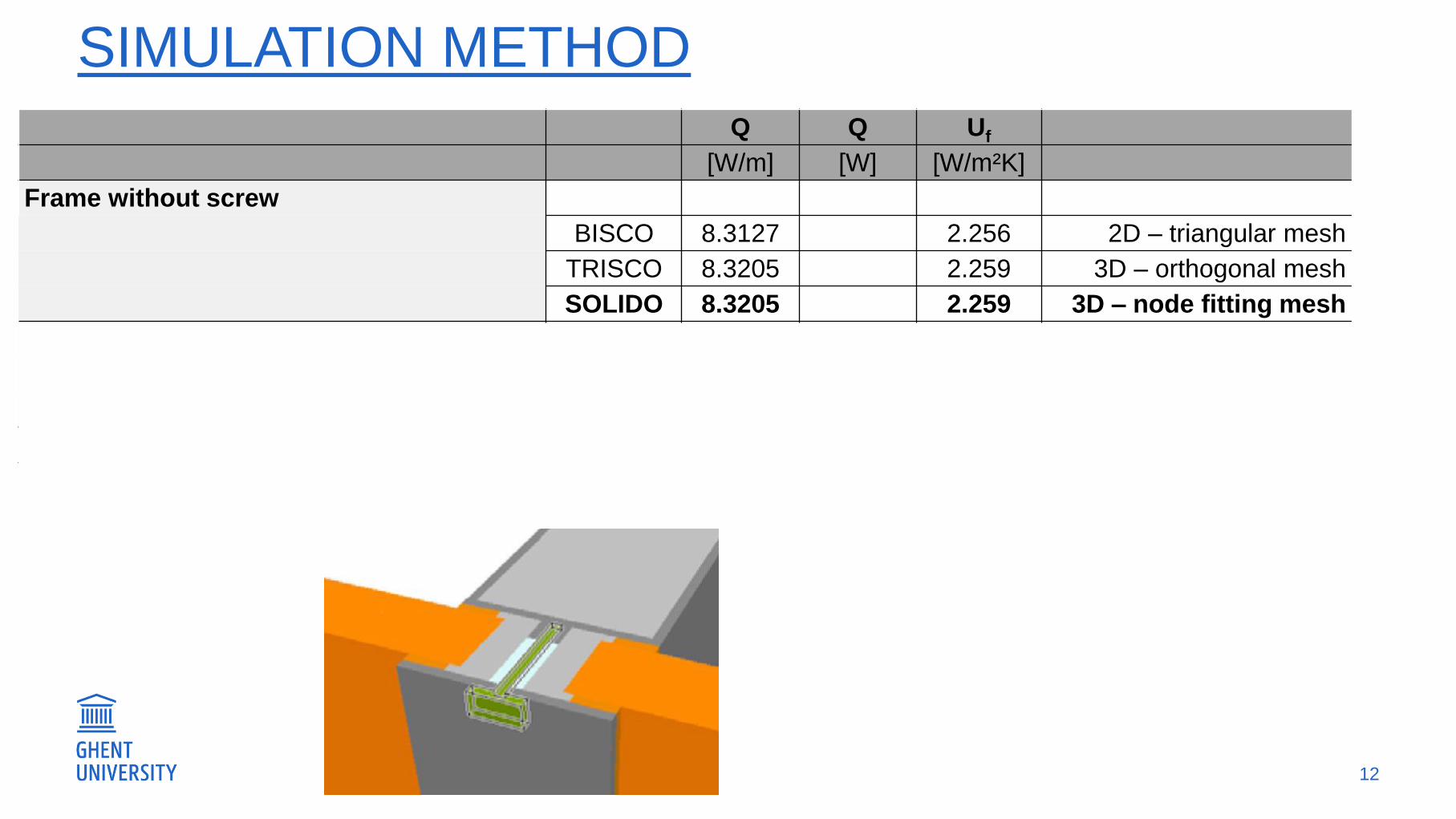
Q Q Uf
[W/m] [W] [W/m²K]
Frame without screw
BISCO 8.3127 2.256 2D – triangular mesh
TRISCO 8.3205 2.259 3D – orthogonal mesh
SOLIDO 8.3205 2.259 3D – node fitting mesh
Frame with screw
SOLIDO 1.1049 2.526 Reference
TRISCO 1.1141 2.564 +2
Smoothed lambda method (EN 13947) BISCO 8.4918 2.363 -6
Smoothed thickness method (EN 13947) BISCO 8.9182 2.585 +2

SIMULATION METHOD
13
Q Q Uf
[W/m] [W] [W/m²K]
Frame without screw
BISCO 8.3127 2.256 2D – triangular mesh
TRISCO 8.3205 2.259 3D – orthogonal mesh
SOLIDO 8.3205 2.259 3D – node fitting mesh
Frame with screw
SOLIDO 1.1049 2.526 Reference
TRISCO 1.1141 2.564 +2
Smoothed lambda method (EN 13947) BISCO 8.4918 2.363 -6
Smoothed thickness method (EN 13947) BISCO 8.9182 2.585 +2

SIMULATION METHOD
14
Q Q Uf
[W/m] [W] [W/m²K]
Frame without screw
BISCO 8.3127 2.256 2D – triangular mesh
TRISCO 8.3205 2.259 3D – orthogonal mesh
SOLIDO 8.3205 2.259 3D – node fitting mesh
Frame with screw
SOLIDO 1.1049 2.526 Reference
TRISCO 1.1141 2.564 +2
Smoothed lambda method (EN 13947) BISCO 8.4918 2.363 -6
Smoothed thickness method (EN 13947) BISCO 8.9182 2.585 +2

SIMULATION METHOD
15
Q Q Uf
[W/m] [W] [W/m²K]
Frame without screw
BISCO 8.3127 2.256 2D – triangular mesh
TRISCO 8.3205 2.259 3D – orthogonal mesh
SOLIDO 8.3205 2.259 3D – node fitting mesh
Frame with screw
SOLIDO 1.1049 2.526 Reference
TRISCO 1.1141 2.564 +2
Smoothed lambda method (EN 13947) BISCO 8.4918 2.363 -6
Smoothed thickness method (EN 13947) BISCO 8.9182 2.585 +2

- CONTEXT
- SIMULATION METHOD
- MODEL
- 10 PARAMETERS
- CONCLUSIONS
16

MODEL – EUROPEAN SECTIONS
17
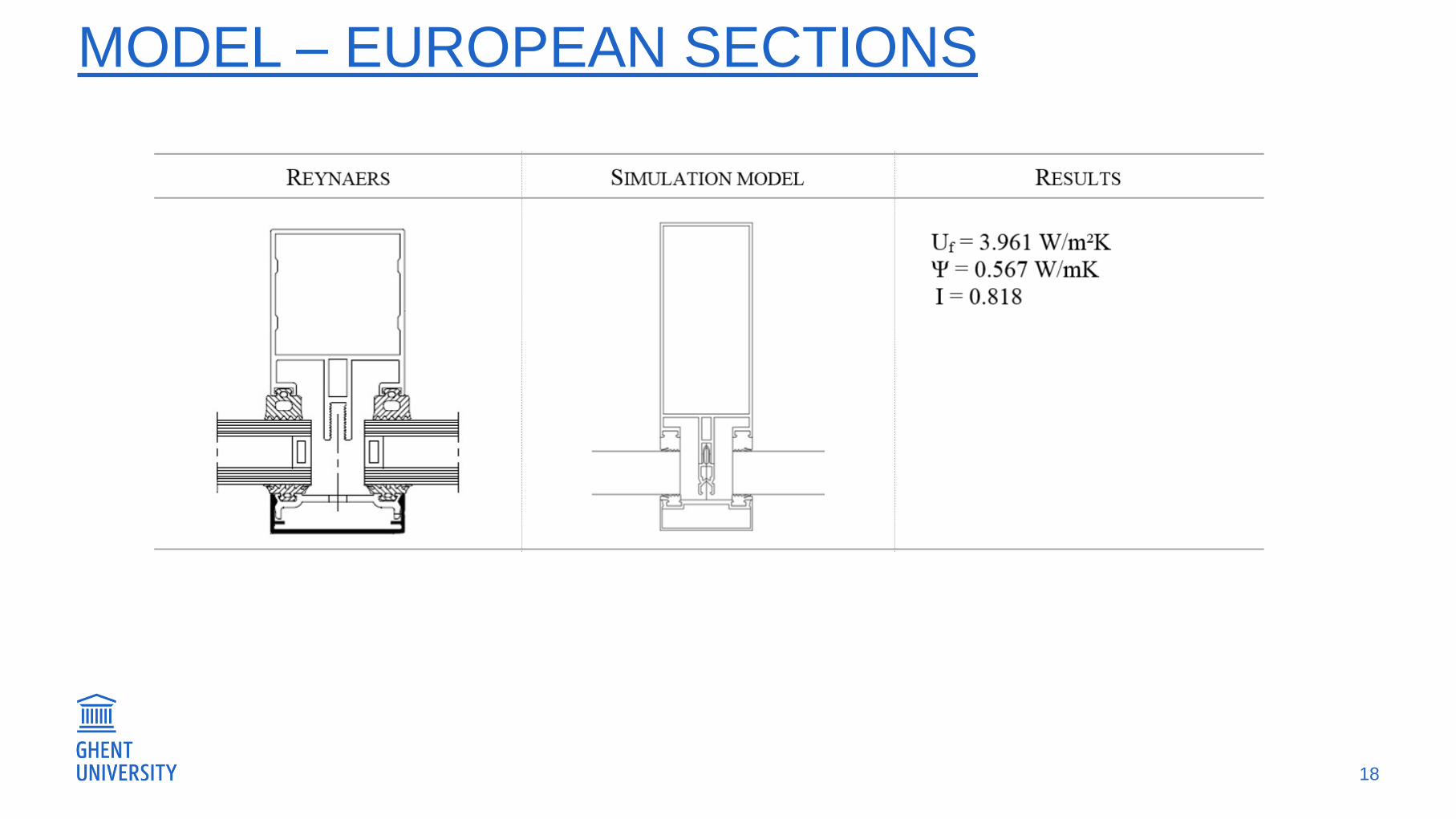
MODEL – EUROPEAN SECTIONS
18

MODEL – EUROPEAN SECTIONS
19

MODEL – NORTH AMERICAN SECTIONS
20

MODEL – NORTH AMERICAN SECTIONS
21
Addition of surface heat transfer
resistance:
0.04 + 0.13 = 0.17 m²K/W
U = 5.88 W/m²K

MODEL – NORTH AMERICAN SECTIONS
22
U = 7.344 W/m²K U = 5.274 W/m²K

MODEL – NORTH AMERICAN SECTIONS
23

MODEL – NORTH AMERICAN SECTIONS
24
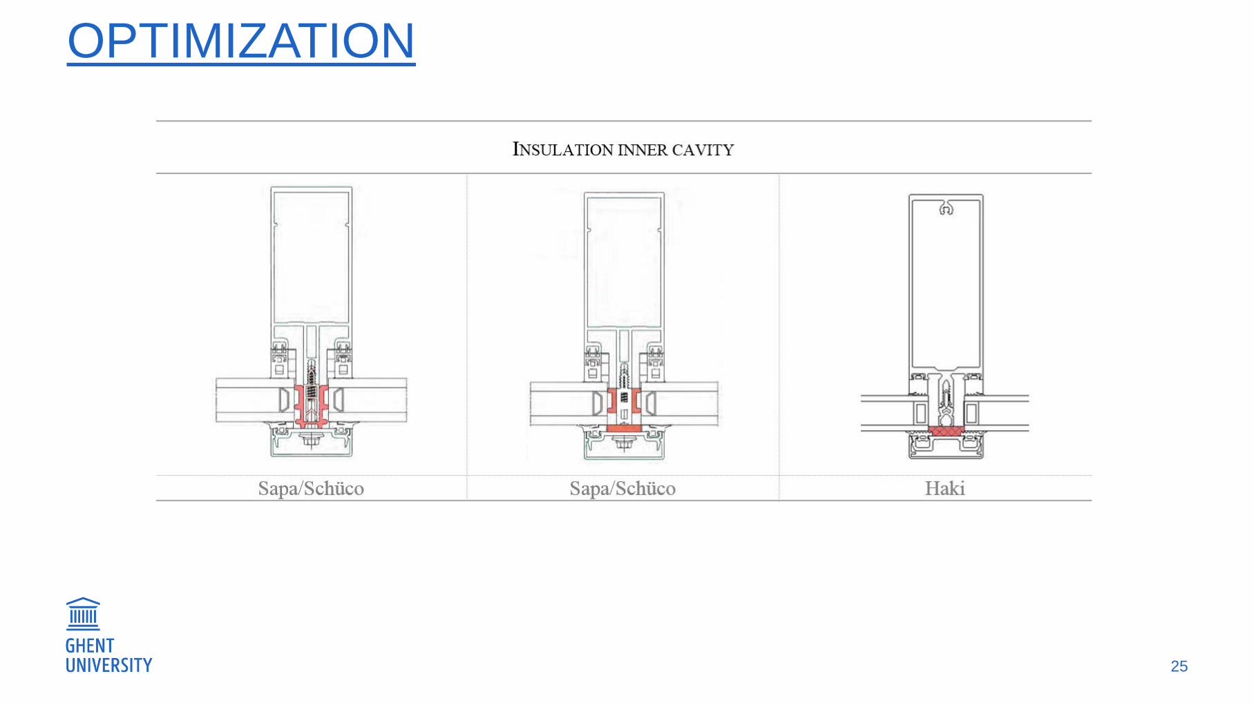
OPTIMIZATION
25

OPTIMIZATION
26
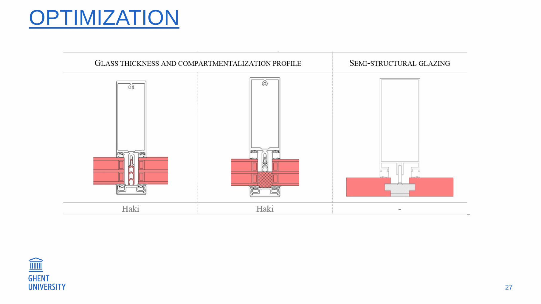
OPTIMIZATION
27

GENERIC PROFILES
28
Europe North-America

GENERIC PROFILES
29
Europe North-America

GENERIC PROFILES
30
Europe North-America

- CONTEXT
- SIMULATION METHOD
- MODEL
- 10 PARAMETERS
- CONCLUSIONS
31

10 PARAMETERS
32

10 PARAMETERS
33

1 & 2. PROFILE WIDTH AND LENGTH
34

1 & 2. PROFILE WIDTH AND LENGTH
35
U-values: -5%

1 & 2. PROFILE WIDTH AND LENGTH
36
Ψ 60mm = 0.576 W/mK
Ψ 50mm = 0.534 W/mK
Ψ –values: -7%
U-values: -5%

1 & 2. PROFILE WIDTH AND LENGTH
37

3. LENGTH OF SCREW FINS
38

3. LENGTH OF SCREW FINS
39

4. POSITION OF THE GLASS UNIT
40
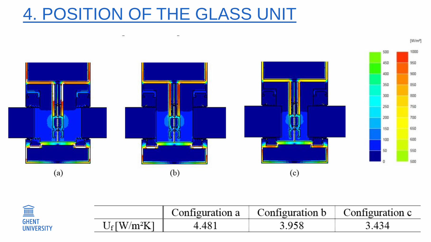
4. POSITION OF THE GLASS UNIT
41

5. SPACING BETWEEN SCREWS
42
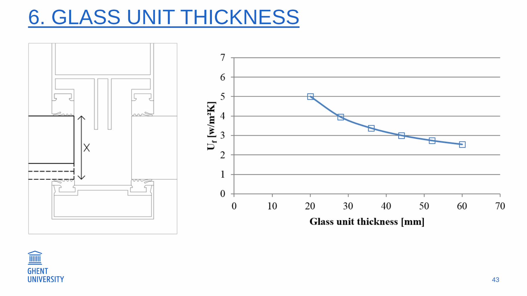
6. GLASS UNIT THICKNESS
43

6. GLASS UNIT THICKNESS
44

6. GLASS UNIT THICKNESS
45

7. -VALUE OF SCREWS
46
λ

8. -VALUE OF COMPARTMENTALIZATION
47
λ

9. SNAP COVER LENGTH
48

9. SNAP COVER LENGTH
49

10. ADDITIONAL INSULATION
50

10. ADDITIONAL INSULATION
51
GFRP frame Polymer pressure plate

10. ADDITIONAL INSULATION
52

- CONTEXT
- SIMULATION METHOD
- MODEL
- 10 PARAMETERS
- CONCLUSIONS
53

CONCLUSIONS
54
Some parameters are taken into account in standard calculations
Following are typically not:
Depth of the frame
Position of IGU
Thickness of IGU
Spacing between screws

IMPACT
55

IMPACT
56

IMPACT
57

IMPACT
58

Thank you for your attention!
Thank you for your attention!
Belgium