THERMAL SYSTEMS FOR INDOOR POOLS UTILIZING HEAT RECOVERY ...
92
JAVIER GONZÁLEZ MIGUEL THERMAL SYSTEMS FOR INDOOR POOLS UTILIZING HEAT RECOVERY FROM EXHAUST AIR Master of Science Thesis Examiner: Professor Timo Kalema Examiner and topic approved by the Council meeting of the Faculty of Engineering Sciences on 9th April 2014
Transcript of THERMAL SYSTEMS FOR INDOOR POOLS UTILIZING HEAT RECOVERY ...

JAVIER GONZÁLEZ MIGUEL
THERMAL SYSTEMS FOR INDOOR POOLS UTILIZING HEAT
RECOVERY FROM EXHAUST AIR
Master of Science Thesis
Examiner: Professor Timo Kalema Examiner and topic approved by the Council meeting of the Faculty of Engineering Sciences on 9th April 2014

i
ABSTRACT TAMPERE UNIVERSITY OF TECHNOLOGY
GONZALEZ MIGUEL, JAVIER: Thermal systems for indoor pools utilizing heat re-
covery from exhaust air Master of Science Thesis, 64 pages, 21 Appendix pages April 2014 Major: Mechanic and design engineering Examiner: Professor Timo Kalema Keywords: Thermal systems, Pools, Heat recovery, HVAC, dehumidifier, chiller.
The number of indoor swimming pools has increased rapidly in the last decade due to
the growing demand of sport activities by the society, looking for healthy lifestyle hab-
its. Following this growing demand, most of the Spanish cities are promoting the con-
struction of sports centres, where all kinds of sports are practiced, including swimming.
The energy efficiency index (ODEX) in Spain has recorded a turning point in 2004
matching with the implementation of the Spanish Strategy of Energy Saving and Effi-
ciency, which implicates more severe requirements in energy efficiency. The remarka-
ble development of renewable energy in recent decades, has led Spain to include a re-
quirement of minimum solar contribution in order to heat the pool water.
Solar thermal energy has undoubtedly a huge future, but need to find new applications
to make it more attractive for both the end user and engineering companies. In Spain
many system and facilities designed nowadays do not aim to save energy and preserve
the environment, they are planned to meet the terms imposed by the new Technical
Building Code. This code is applied to new buildings and rehabilitation of existing
buildings for any use where there is a demand for hot water or air conditioning in indoor
pools.
Along this document, a complete system to heat the pool water and condition the air in a
pool enclosure in Spain will be designed. A chiller with a heat recovery system and a
system that dehumidify the air from the pool with the option of recovering energy for
heating purposes will be used instead a solar system as the Spanish regulations require
and it will be shown that the energy input obtained from these systems is higher than the
one obtained through solar panels.

ii
PREFACE
I wrote this Master Thesis during my stay in Tampere, Finland in the academic year
2013-2014.
I would like to thank Professor Timo Kalema for giving me the opportunity of doing my
Master Thesis in TUT and for his guidance and feedback.
Finally I would like to thank my family and friends, because they always support and
encourage me to achieve all my goals.
Javier González Miguel
iii
TABLE OF CONTENTS
Abstract .............................................................................................................................. i
Preface ............................................................................................................................... ii
Table of contents .............................................................................................................. iii
Terms and definitions ....................................................................................................... iv
1. Introduction ............................................................................................................... 1
2. Background ............................................................................................................... 2
2.1 Dehumidification System .................................................................................. 2
2.1.1 Air Conditioning Psychrometrics ........................................................ 2
2.1.2 Indoor Pool dehumidification .............................................................. 6
2.1.3 Heat Loss in the Swimming Pools ..................................................... 10
2.1.4 System start-up power requirement ................................................... 14
2.1.5 Dehumidification needs ..................................................................... 15
2.2 Chiller .............................................................................................................. 16
2.2.1 Load calculation ................................................................................. 18
3. Case study ............................................................................................................... 22
3.1 Building Description ....................................................................................... 22
3.2 System Description ......................................................................................... 23
3.3 Building energy demand ................................................................................. 28
3.3.1 Heat loss of the pool .......................................................................... 28
3.3.2 Building Load Calculations ............................................................... 33
3.4 Swimming Pool Dehumidification System ..................................................... 36
3.5 Air diffusion in the pool enclosure.................................................................. 41
3.6 Airduct Design ................................................................................................ 44
3.7 Chiller .............................................................................................................. 51
3.8 Boiler ............................................................................................................... 53
3.9 Pumps .............................................................................................................. 55
3.10 Heat Exchangers.............................................................................................. 57
3.11 Final System Diagram ..................................................................................... 58
4. Comparative with a solar system ............................................................................ 60
5. Conclusion .............................................................................................................. 63
References ....................................................................................................................... 65
Apendix A: Pump Performance Curves .......................................................................... 67
Appendix B. Solar Collectors system ............................................................................. 70
Appendix C. Space distribution for Load calculation ..................................................... 73
Appendix D. Diffusion study charts ............................................................................... 84

iv
TERMS AND DEFINITIONS
HVAC: Heating, ventilation, and air conditioning
DHW: Domestic hot water
ASHRAE: American Society of Heating, Refrigerating and Air Conditioning Engineers
RITE: Spanish regulation for thermal installations in buildings
CTE: Technical Building code
SHR: Sensible heat ratio
AHU: Air Handling Unit
HAP: Carrier’s Hourly Analysis Program
Mca: Water column meters (1 bar = 10,2 mca)
Mmca: Water column millimetres
EER: Energy Efficiency Ratio
SEER: Seasonal Energy Efficiency Ratio
F: heating effect
Q: heating energy
P: Mechanical power
: mass flow
p: pressure
cp: Specific heat
T: Temperature

v
hc: Convective Heat Transfer Coefficient
: Volume flow rate
ρ: Density
Ui: Heat transfer coefficient
S: Surface area
h: Enthalpy
t: Time
V: Volume
Φel: Evaporation energy loss
Φrl: Radiation energy loss
Φcl: Convection energy loss
Φcond: Conduction energy loss
σ: Stefan-Boltzman constant
W: Humidity ratio
ε: Emissivity
φ: Relative humidity
l: vaporization latent heat
1
1. INTRODUCTION
This project aims to study and design the facilities needed to condition the indoor air of
a pool enclosure, in order to maintain its temperature, humidity and air movement at
optimum levels for the users comfort. The realization of this project is led by the desire
to improve the efficiency of systems in indoor pools due to the significant increase who
have suffered this type of facility in Spain in recent years and the amount of energy they
need.
In Spain the Technical Building Code enforces the installation of solar systems to heat
partially the pool water, for this reason, that kind of systems are usually included in
sport centre facilities.
That solution is usually planned to meet the terms, without seeking to save energy and
preserve the environment, instead of designing a system using the existing installations
destined to other purposes that could improve the energy efficiency.
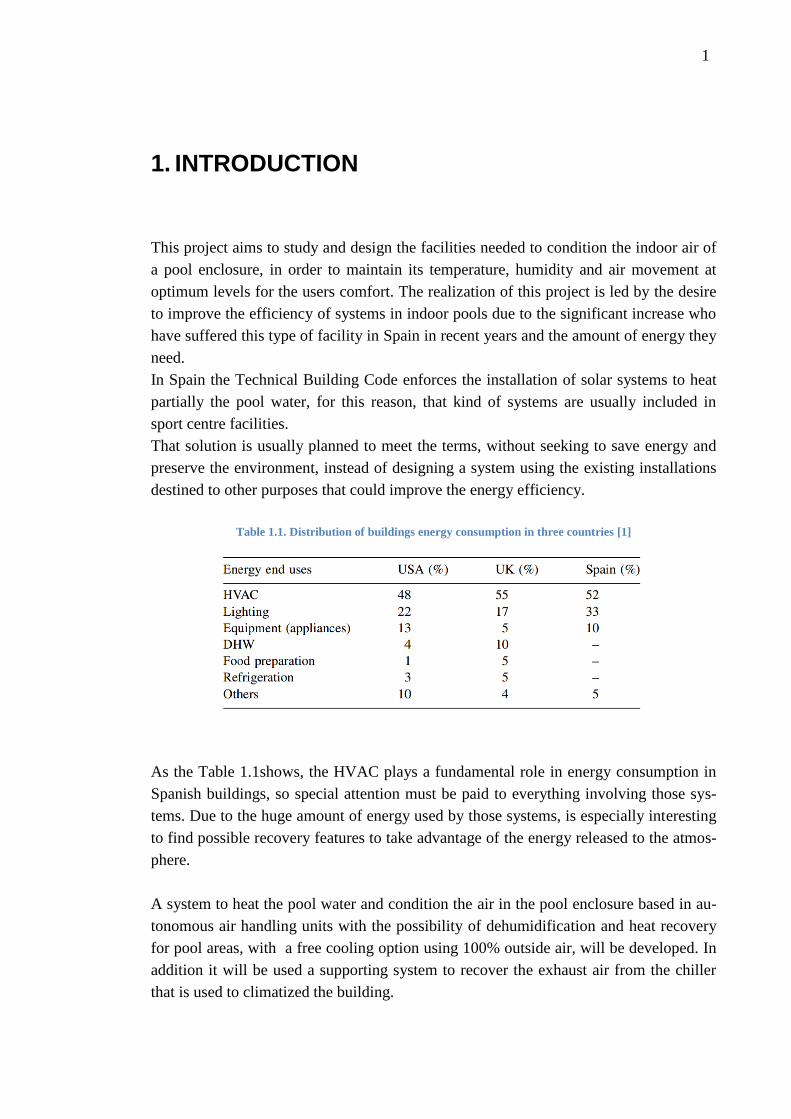
Table 1.1. Distribution of buildings energy consumption in three countries [1]
As the Table 1.1shows, the HVAC plays a fundamental role in energy consumption in
Spanish buildings, so special attention must be paid to everything involving those sys-
tems. Due to the huge amount of energy used by those systems, is especially interesting
to find possible recovery features to take advantage of the energy released to the atmos-
phere.
A system to heat the pool water and condition the air in the pool enclosure based in au-
tonomous air handling units with the possibility of dehumidification and heat recovery
for pool areas, with a free cooling option using 100% outside air, will be developed. In
addition it will be used a supporting system to recover the exhaust air from the chiller
that is used to climatized the building.

2
2. BACKGROUND
2.1 Dehumidification System
2.1.1 Air Conditioning Psychrometrics
In order to understand the operation of our dehumidification system, an approach to the
air conditioning psychrometrics theory will be done.
2.1.1.1 Composition of dry and moist air
According the ASHRAE's 2009 handbook, three basic definitions are used to describe
air under different conditions [2]:
Atmospheric air has many gaseous components (nitrogen, carbon dioxide, oxygen …)
as well as water vapour and contaminants such as dust, pollen or smoke. This is the air
used for ventilation.
Dry air is atmospheric air without water vapour and contaminants. By volume, dry air
contains approximately 78% nitrogen, 21% oxygen, and 1% of other gases. Dry air is
used as the reference in psychrometrics (Figure 2.1).
Moist air is a combination of dry air and water vapour. The amount of water in moist
air varies from zero, dry air, to a maximum defined by the temperature and pressure.
Figure 2.1. Dry Air Composition in Atmosphere

3
2.1.1.2 Psychrometric Chart
A psychrometric chart graphically provides the thermodynamic properties of moist air
and the relationship between them, like dry bulb temperature, in vertical lines, wet bulb
temperature and enthalpy, the lines sloping downward to the right, dew point tempera-
ture, the horizontal lines, and relative humidity, the curves. Two properties can be de-
termined with any two of the others.
The ASHRAE psychrometric chart (Figure 2.2) can be used to solve mostly every pro-
cess problems with moist air.
Figure 2.2.ASHRAE Psychrometric Chart
According to the ASHRAE Guide, the basic parameters relating the humidity that de-
termine the state or condition of the air at any particular time are the ones below [2]:
- Humidity ratio W is defined as the relation between the mass of water vapour
and the mass of dry air.
W = Mw /Mda (1)
- Specific humidity γ is the fraction of the mass of water vapour in the total mass
of the moist in an air sample:
γ = Mw /( Mw + Mda)= W/(1 + W) (2)
- Absolute humidity is the fraction of the mass of water vapour in the total vol-
ume of an air sample:
dv = Mw /V (3)

4
- Saturation humidity ratio Ws(t, p) is the humidity ratio of moist air saturated
with respect to water at the same conditions of temperature and pressure.
- Degree of saturation μ is the ratio of air humidity ratio W to humidity ratio Ws
of saturated moist air at the same conditions of temperature and pressure.
μ = W /Ws (4)
- Relative humidity φ is the ratio of the mole fraction of water vapour Xw in the
air to the mole fraction of water vapour present in saturated air Xws in an air
sample at the same conditions of temperature and pressure. Basically, relative
humidity is the ratio of the actual moisture content of the air to the maximum
possible quantity of moisture that the air could have at the same temperature, so
if the relative humidity is 100%, the air is completely saturated. The Figure 2.3
shows the representative lines of the relative humidity in the chart.
φ = X /Xs (5)
Figure 2.3. Relative Humidty Lines in the Psychrometric Chart
- Dew-point temperature Td is the temperature of moist air saturated at the same
pressure p, with the same humidity ratio W, as that of the given sample of moist
air.
- Wet-bulb temperature T* is a temperature related with the content of moisture
in the air, the temperature is taken by covering the thermometer with a wet wick
and measuring the reading as the water evaporates. Because of the cooling effect
of evaporation, dry bulb temperature is always higher than dry temperature and
only is the same at saturation. Wet bulb temperature on psychrometric chart is

5
symbolized by lines with a slope from the upper right of the chart down to the
lower left (Figure 2.4).
Figure 2.4.Wet-Bulb Temperature Constant Lines in the Psychrometric Chart
- Dry Bulb Temperature is the temperature measure with a regular thermometer.
It will be considered the temperature of the air as the dry bulb temperature. In
the psychrometric chart Dry-bulb temperature is found on the horizontal axis,
represented by vertical chart lines (Figure 2.5).
Figure 2.5.DryBulb Temperature Constant Lines in the Psychrometric Chart

6
2.1.2 Indoor Pool dehumidification
Humidity аnd moіѕture frоm аn indoor рoоl can produce several damages if a pool de-
humidifier is not sized and installed properly. Several methods can be used to dehumidi-
fy an indoor pool facility, but the variable that most greatly impacts the operating cost is
the outside weather. The main goal of any dehumidification system is to keep the indoor
air in the enclosure at the optimum conditions of temperature and humidity. The second
goal is to achieve the previous one in the most effective way with the lowest cost. An
evaluation of the effectiveness of each method and an approach to the different humidi-
ty control systems and their associated purchase, installation and operation costs will be
done[3].
2.1.2.1 Push-pull ventilation
Figure 2.6. Principle of push-pull ventilation
A ventilation “push-pull” system wastes an important amount of energy by exhausting
both sensible and latent heat of the enclosure introducing outdoor air (Figure 2.6). The
outdoor air flow depends on the difference between the outdoor and indoor absolute
humidity and it is necessary to adapt the supply air temperature with a preheating.
These systems will have similar operational costs in different climatic regions. In
warmer zones, a higher outdoor air flow is required, but the cost to heat the outdoor air
is smaller. In colder zones, a smaller outdoor air flow is required to dehumidify the air
but significant heating costs will be needed (Table 2.1).

7
Table 2.1. Properties of push-pull ventilation
ADVANTAGES DISADVANTAGES
• Low system cost to purchase
• Low system cost to install
• High operation cost
• Limitations in humidity and temperature control
• Cooling not available on summer
In Spain the Regulation for Thermal Installations in Buildings (RITE) [4] has added a
requirement of an air-to-air heat exchanger in last years, for this reason the system ex-
posed before are no longer used in this kind of buildings.
2.1.2.2 Push-pull ventilation with air-to-air heat exchanger
Figure 2.7. Ventilation with Heat Recovery
This method is a variation of the system studied before, including an air-to-air heat ex-
changer with heat recovery purposes. The incoming outdoor air flows through a series
of plates and recovers the heat of exhaust air that is at a higher temperature (Figure 2.7).
The outdoor air flow has to be preheated, decreased, or somewhat bypassed when out-
door temperature is low. Efficiency is considerably reduced under low ambient envi-
ronments. At cold temperatures, the need of recovery is higher and the exchanger shows
the minimum recovery capacity, besides, at high outdoor temperatures cooling is not

8
possible. When outdoor temperature and humidity are higher than the inside a condition,
the heat recovery system does not perform as required (Table 2.2).
Table 2.2. Properties of a ventilation system with heat recovery
ADVANTAGES
DISADVANTAGES
• Sensible heat recovery system
• Energy saving
• Low seasonal efficiency
• High system cost to purchase
• Does not recover all the latent heat
• Limitations in humidity and temperature control
2.1.2.3 Standard dehumidifier
Figure 2.8. Standard dehumidifier
Three decades ago a refrigerant- based dehumidifier was designed to remove the mois-
ture in a pool enclosure. It was the first time the outdoor conditions did not determine
the system operation. The dehumidification process acted as a heat pump, turning into
an energy recovery system, which returned both the sensible and latent energy back to
the pool enclosure and pool water (Figure 2.8).
As the humidity is controlled by the dehumidifier, the outdoor air flow can be stopped
or reduced in order to save energy.

9
This dehumidifier works like an air conditioner in the summer, recovering energy to
heat the pool water (Table 2.3).
Table 2.3. Properties of a dehumidification system
ADVANTAGES
DISADVANTAGES
• Heat recovery system
• Air conditioning
• Full humidity control
• High system cost to purchase
• High system cost to install
This is the basic system, but nowadays incorporates other features like free-cooling
module, multi-stage filtration or support electric heaters.
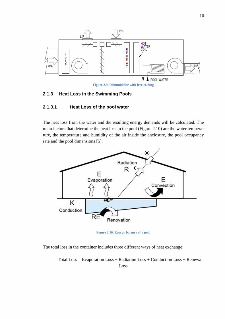
2.1.2.4 Dehumidifier with “free cooling”
Through certain periods of the year, ventilation air is more effective itself than refrigera-
tion dehumidification. This system works like an air conditioner with a saving mode,
turning off the compressor when is possible to take advantage of free cooling because of
the outdoor temperature (Figure 2.9).
In Spanish Regulation for Thermal Installations in Buildings [4] there is a requirement
of free-cooling in systems with high powers, it will be mandatory in some circumstanc-
es.
The economizer will work only when all control points are acceptable. An economizer
usually provides free cooling only 5% -20% of the year. The economizer works only a
small fraction of the year, and the system essentially acts like a standard dehumidifier
the remainder of the year. This dehumidifier presents a lot of advantages (Table 2.4).
Table 2.4. Properties of a free cooling dehumidifier
ADVANTAGES
DISADVANTAGES
• Full humidity control.
• Energy savings by free cooling
• Energy savings by heat recovery
• Air conditioning
• High system cost to purchase
• High system cost to install
• High operational cost
10
Figure 2.9. Dehumidifier with free cooling
2.1.3 Heat Loss in the Swimming Pools
2.1.3.1 Heat Loss of the pool water
The heat loss from the water and the resulting energy demands will be calculated. The
main factors that determine the heat loss in the pool (Figure 2.10) are the water tempera-
ture, the temperature and humidity of the air inside the enclosure, the pool occupancy
rate and the pool dimensions [5].
Figure 2.10. Energy balance of a pool
The total loss in the container includes three different ways of heat exchange:
Total Loss = Evaporation Loss + Radiation Loss + Conduction Loss + Renewal
Loss

11
Evaporation loss: When the water evaporates from the surface of the pool a cooling of
the rest of the pool is produced, so a decrease in the water temperature. Evaporation
from the water surface will be higher, the greater the occupancy rate of the pool, and in
particular the number of swimmers, because of the interaction between water and air in
the turbulent flow created as a result of splash, stimulating evaporation. To calculate
evaporation loss the formula below is used:
Φel = l S (W) (6)
- l is the vaporization latent heat (680
)
- is the evaporated mass flow per surface area and follows the equa-
tion proposed by Bernier:
= (16 + 133 n) (Ww – φ Wa) + 0,1N (
) (7)
This expression takes into account two empirical factors: evaporation as-
sociated with the pool without water movement (coefficient 16) and
evaporation associated with the splashing of the swimmers (coefficient
133n).
- n is the occupancy rate (
) with the usual values 0 / 0,1 / 0,15 /
0,2 .
- Ww and Wa are the humidity ratio in saturation state, at dew point, at the
water temperature and at room temperature. (
).
- φ is the relative humidity.
- S is the area from the water surface m2.
- N is the number of spectators.
Another equation for the evaporated mass flow considering the air veloc-
ity V could be used, as the one below proposed by Carrera, however, the
difference between them is negligible [6].
= 9 (Ww - Wa) (1+V/1,20) S + 0,42 n + 0,08 N (8)

12
Radiation loss: To calculate the water loss due to radiation, Stefan Boltzmann formula
is used. The heat exchange is a function of the difference between the average tempera-
ture of the walls and the water.
Φrl = σ ε (Tw4 – Tenc
4) S (W) (9)
- σ is the Stefan-Boltzman constant ( 5,67 . 10-8
)
- ε is the Water emissivity (0,95)
- Tw is the Water temperature (K)
- Tenc is the enclosure walls temperature (K)
In an indoor pool, we need to add the radiation shape factor:
Φrl = σ .ε . (Tw 4
– T”enc 4
) S F (W) (10)
- T”enc is the average of all the enclosure walls
- F is Radiation shape factor
Convection loss: The heat exchange between the water of the pool and the air of the
enclosure due to the temperature difference between the two of them causes the follow-
ing heat loss.
Φcl = hc (Tw – Ta) S = 0,6246 (Tw – Ta)4/3
S (W) (11)
- hc = 0,6246 . (
) ( Tw– Ta)1/3
[5]
- hc is the Convective Heat Transfer Coefficient (
)
- Tw is the water temperature (ºC)
- Ta is the air temperature (ºC)
Renewal loss: In an indoor swimming pool, there is a continuous water loss originated
by evaporation, swimmers or maintenance. However, these amounts are less than the
minimum renewal flow rate required by law for hygiene reasons, which varies from
1/40 - 1/50 the volume of water per day. This renewal means that heat loss will depend
on the temperature of the water in the system and the temperature of the pool water and
can be calculated using the following formula:
Φre = RE ρ Cp. (Tw – Tx) (W) (12)
- RE is the renewal flow rate
- ρ is the density of water (1000 kg/ m3)
- Cp is the specific heat (1,16
)

13
- Tw is the water temperature in the pool (ºC)
- Tx is the water temperature in the system (ºC)
Conduction loss from floor: This loss depends on the floor structural characteristics
surrounding the pool and the heat transfer coefficient of the material used.
Commonly a concrete floor is used and transmission loss is calculated using the formu-
la:
Φcond = ΣUK SK (Tw – Text) (W) (13)
- UK is the Heat transfer coefficient of the floor surrounding the pool (
)
- SK is the heat exchange area (m2)
- Tw is the water temperature (ºC)
- Text is the temperature outside in the surroundings of the pool container
(ºC)
2.1.3.2 Heat loss in the pool enclosure
The heat transfer from the pool atmosphere to outside is divided in two ways of energy
exchange, conduction through the enclosure and the energy exchange between the air
from the outside and the air from the pool zone.
ΦT = Φ1 + Φ2 (14)
Conduction loss through the enclosure: Walls, windows and other elements will be
considered.
Φ1 = Σ Ui Si (Tin – Tout) (W) (15)
- Ui is the Heat transfer coefficient of the floor surrounding the pool (
)
- Si is the surface area (m2)
- Tin is the temperature inside the enclosure (ºC)
- Tout is the temperature outside the enclosure (ºC)
Energy necessary to heat the air from outside: The renewal air flow rate needed will
be calculated taking into account different values for swimmers, that can be swimming
or not, or visitors, that never swim.
Φ2 = ρE (hin – hout) (W) (16)

14
- is the renewal air flow (m3/h) = N S 22 + n S 36
o Swimmer: 36 m3/h
o Visitor: 22 m3/h
- ρE is the outside density air 1,2 (
)
- hin is the enthalpy of the air at the indoor temperature
- hout is the enthalpy of the air at the outdoor temperature
- cp is the air specific heat ( 0,28
)
- n is the occupancy rate (
) and N (
)
- S is the area from the water surface (m2)
2.1.4 System start-up power requirement
In this section, the heating power to ensure the system start-up is calculated after the
pool is completely filled with water. This power is calculated by the expression below,
which includes the energy needed to heat the water, the pool walls and the heat loss
from the water surface.
Φ start-up = Φ water + Φ walls + Φ loss (17)
where the power to heat the water is obtained from the expression:
Pwater = –
(W) (18)
- V is the volume of water (m3)
- ρ is the water density (1000 kg/m3)
- C is the water specific heat ( 1,16
)
- Tw is the temperature of the pool water (ºC)
- Tsup is the temperature of the water supply (ºC)
- t is the start-up time (usually 96 h)
The expressions to calculate the power necessary to heat the walls and the loss from the
water surface were explained in the previous chapter. This loss includes the originated
by radiation, convection and evaporation.

15
2.1.5 Dehumidification needs
Evaporation from the water surface defines the dehumidification needs. It will be great-
er the higher the occupancy of the pool, and in particular the number of swimmers.
There are other causes that could increase the pool air humidity as the visitors or public
which is an important issue in swimming competitions, because the occupation of the
stands is high, or the outside air ventilation.
In accordance with the equation used before the evaporated mass flow per hour follows
the equation proposed by Bernier [5]. This flow will define the dehumidification capaci-
ty:
= (16 + 133 n) (Ww – φ Wa) + 0,1N (
) (19)

16
2.2 Chiller
There are two essential HVAC systems designed to fulfill building cooling require-
ments, direct expansion systems and secondary refrigerant systems. In the first ones, the
heat exchange between the refrigerant and the air is done directly in the units. In the
second ones, chilled water is used as an intermediate medium to cool the air [7].
In water systems, one source is responsible of providing cooling throughout the whole
building, and offers many reliability and efficiency advantages over individual expan-
sion systems with a considerably lower total cost. The source of a HVAC cooling sys-
tem are one or more water chillers, designed to collect the heat from the air building
rejecting to the outdoor air in many cases.
The water chiller may have various configurations, with helical screw compressors, or
centrifugal type and with different engine movers. The heat can be rejected to the at-
mosphere directly from the refrigerant to the air, or collecting the heat previously from
the refrigerant with water. A water-cooled system usually offers advantages over an air-
cooled system, as smaller size, longer lifecycle or better efficiency.
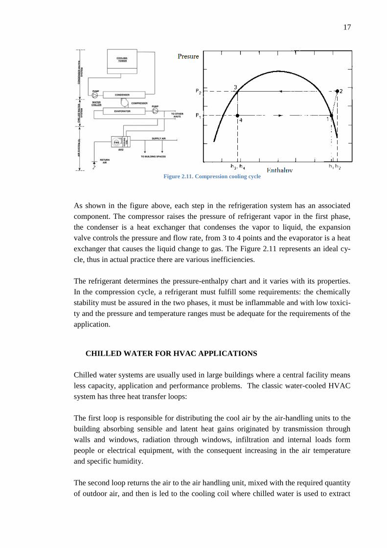
Vapor Compression Refrigeration Cycle
A chiller based its operation in a compression refrigeration cycle where a refrigerant
evaporates from liquid to gas absorbing heat and providing a cooling effect and conden-
sates from gas to liquid generating heat. The refrigeration cycle can be explained in four
steps using the Figure 2.11:
1. Compression (1-2): In this stage, low-pressure refrigerant vapor is compressed
from P1 to P2 with a parallel growth in temperature.
2. Condensation (2-3): The refrigerant at high pressure is cooled with air or water
and condenses to a high pressure liquid.
3. Expansion (3-4): The high pressure liquid flows through the expansion valve de-
creasing the pressure and a percentage of the liquid changes to gas.
4. Evaporation (4-1): The liquid at low pressure receives heat from air or water
evaporating. The low pressure vapor is led to the compressor repeating the cycle.
17
Figure 2.11. Compression cooling cycle
As shown in the figure above, each step in the refrigeration system has an associated
component. The compressor raises the pressure of refrigerant vapor in the first phase,
the condenser is a heat exchanger that condenses the vapor to liquid, the expansion
valve controls the pressure and flow rate, from 3 to 4 points and the evaporator is a heat
exchanger that causes the liquid change to gas. The Figure 2.11 represents an ideal cy-
cle, thus in actual practice there are various inefficiencies.
The refrigerant determines the pressure-enthalpy chart and it varies with its properties.
In the compression cycle, a refrigerant must fulfill some requirements: the chemically
stability must be assured in the two phases, it must be inflammable and with low toxici-
ty and the pressure and temperature ranges must be adequate for the requirements of the
application.
CHILLED WATER FOR HVAC APPLICATIONS
Chilled water systems are usually used in large buildings where a central facility means
less capacity, application and performance problems. The classic water-cooled HVAC
system has three heat transfer loops:
The first loop is responsible for distributing the cool air by the air-handling units to the
building absorbing sensible and latent heat gains originated by transmission through
walls and windows, radiation through windows, infiltration and internal loads form
people or electrical equipment, with the consequent increasing in the air temperature
and specific humidity.
The second loop returns the air to the air handling unit, mixed with the required quantity
of outdoor air, and then is led to the cooling coil where chilled water is used to extract

18
heat from the air to redistribute it later. This process produces a water temperature in-
crease so the water leaving will be 3-8ºC warmer than the chilled supply water. The
warmer water return to the chiller where it is cooled to send it back to the AHU unit, the
compressor is the element that consumes energy in the process.
The compressor produces an amount of heat that depends on the efficiency of the com-
pressor so a last loop can be considered. This heat of compression must be taken into
account to establish the amount of heat that must be rejected by the condenser to the
outdoor air.
Water Supply Temperature
In order to calculate a chilled water system, firstly it is necessary to determine the re-
quired water supply temperature. The sensible and latent cooling loads must be con-
trolled by the system regulating temperature and humidity simultaneously.
Sensible cooling is the decrease of the temperature of the air without any change in
its moisture content. Sometimes the occupants, outdoor air or internal processes intro-
duce moisture in the air causing uncomfortable atmospheres, so that to remove this ex-
cess moisture the air must be cooled below its dew point. Latent cooling is that amount
of heat removed without any change in the air temperature. The total cooling load need-
ed by a space on the water cooling coil is imposed by the sum of the previous two.
The supply air temperature required is imposed by the desired space temperature and
humidity and the sensible heat ratio (SHR) calculated by dividing the sensible heat by
the total heat.
2.2.1 Load calculation
Every solution to a engineering problem starts with a calculation of the duty which must
be met, in this case to quantify the heating and cooling loads in the spaces to be condi-
tioned. Modern practice is to use programs for load calculations, many load calculation
software exist, with different degrees of complexity and accuracy.
In order to do an energy balance in our building the Carrier’s Hourly Analysis Program
(HAP) will be used [8]. HAP is a computer software which assists engineers in design-
ing HVAC systems for buildings.
The software completes the following tasks, according the HAP user’s guide:
- Calculates design cooling and heating loads for spaces, zones, and coils
in the HVAC system.
- Determines required airflow rates for spaces, zones and the system.
19
- Sizes cooling and heating coils.
- Sizes air circulation fans.
- Sizes chillers and boilers.
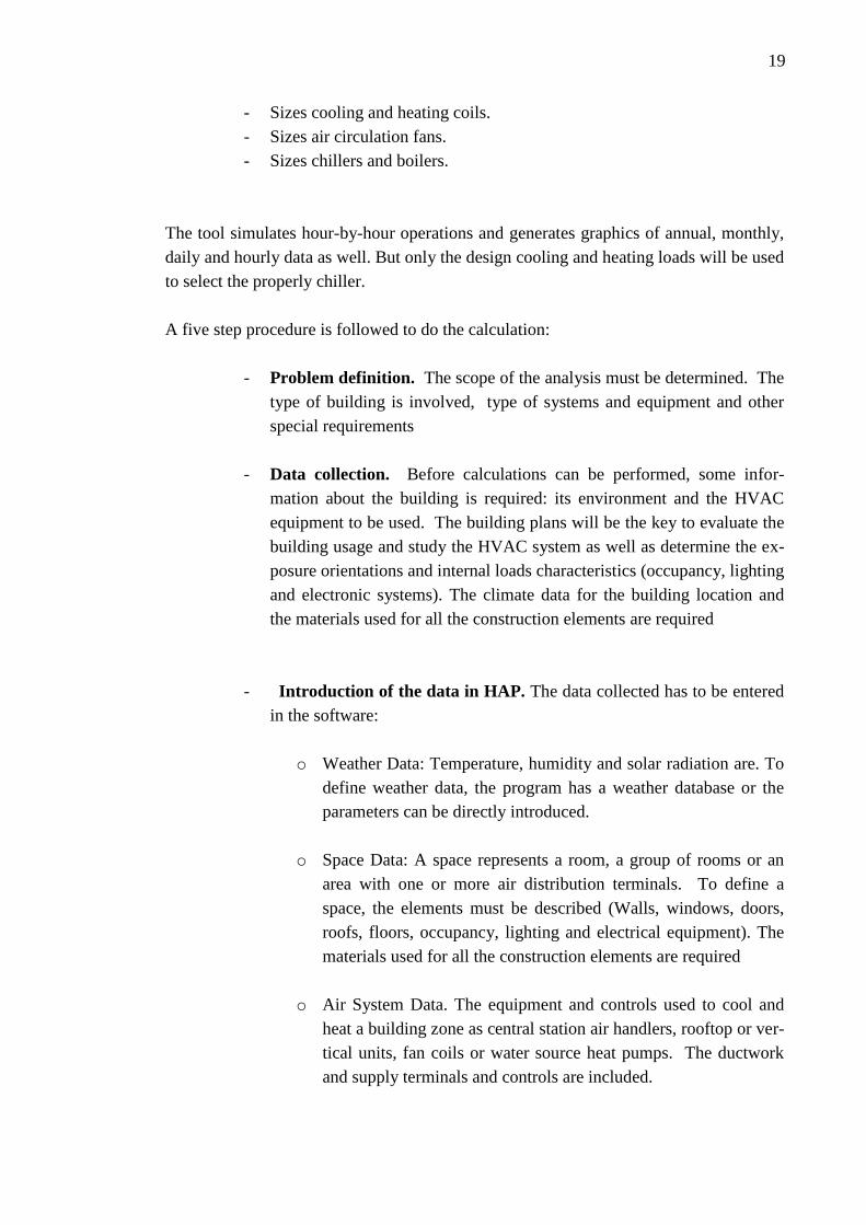
The tool simulates hour-by-hour operations and generates graphics of annual, monthly,
daily and hourly data as well. But only the design cooling and heating loads will be used
to select the properly chiller.
A five step procedure is followed to do the calculation:
- Problem definition. The scope of the analysis must be determined. The
type of building is involved, type of systems and equipment and other
special requirements
- Data collection. Before calculations can be performed, some infor-
mation about the building is required: its environment and the HVAC
equipment to be used. The building plans will be the key to evaluate the
building usage and study the HVAC system as well as determine the ex-
posure orientations and internal loads characteristics (occupancy, lighting
and electronic systems). The climate data for the building location and
the materials used for all the construction elements are required
- Introduction of the data in HAP. The data collected has to be entered
in the software:
o Weather Data: Temperature, humidity and solar radiation are. To
define weather data, the program has a weather database or the
parameters can be directly introduced.
o Space Data: A space represents a room, a group of rooms or an
area with one or more air distribution terminals. To define a
space, the elements must be described (Walls, windows, doors,
roofs, floors, occupancy, lighting and electrical equipment). The
materials used for all the construction elements are required
o Air System Data. The equipment and controls used to cool and
heat a building zone as central station air handlers, rooftop or ver-
tical units, fan coils or water source heat pumps. The ductwork
and supply terminals and controls are included.

20
- Design Reports. Once all the data has been introduced, HAP generates a
system report. The report options can be selected as desired.
- Equipment selection. Finally, with the data from the reports, the system
equipment can be selected.
HAP organizes information about the building and equipment into five categories:
- Element: Is a component of the building structure.
- Space: Is a building zone comprised of elements
- Zone: Is a group of spaces with a thermostatic control.
- Air system: Is the equipment used to provide cooling and heating to a
building zone
- Building: Is the structure that contains all the systems studied.
The Hourly Analyses program is validated by many standards and regulations organiza-
tions. As the ASHRAE 90.1 - 2001 [9] and the ASHRAE 140 – 2001 [10]
Figure 2.12. Accuracy and complexity of various thermal loads calculation methods

21
In the Figure 2.12 are displayed some different methods to calculate thermal loads. The
Heat balance procedure is the most rigorous method for calculating thermal loads of
buildings, evaluating conduction, convection, radiation and heat storage thermal pro-
cesses, using the fundamental laws of Thermodynamics and Heat Transfer, but its com-
plexity, since differential equation has to be solved, do it not suitable to resolve this
kind of problem.
The Transfer Function Method (TFM) used by this software is characterized by its accu-
racy and flexibility. It uses mathematical algorithms simplifying the energy balance
method and improving the software calculation time. This method applies a series of
weighting factors, known as conduction transfer function (CTF) coefficients to the dif-
ferent exterior surfaces and to differences between air temperature and inside space
temperature to determine heat gain with proper reflection of thermal inertia of such sur-
faces. Solar heat gain through glass and various forms of internal heat gain are calculat-
ed directly for the load hour of interest.
The TFM applies a second series of weighting factor, called room transfer functions
(RTF), to heat gain and cooling load values from all load elements having radiant com-
ponents, to account for the thermal storage effect in converting heat gain to cooling
load. Both evaluation series consider data from several previous hours as well as the
current hour [11].

22
3. CASE STUDY
3.1 Building Description
The project developed in this thesis refers to a sport centre located in Segovia, Spain.
The sport centre is placed in a plot of 78,000 m² in the district of Albuera.
The building is designed for sports use, surrounded by other sport facilities as football
fields, an outdoor recreational pool, athletics and tennis courts (Figure 3.1).
Figure 3.1. Sport centre layout
The new complex is divided in four sport areas: water sports, fitness, group sports, and
paddle courts located outside. The sport centre is a three-floor building. In the ground
floor, accessible from the street level, we can find the entrance, distribution corridors,
information point, management office, multipurpose area and administration office.
Also the water activity and swimming pool enclosure, with their own general and staff
locker rooms.
In the first floor are located the rooms for individual or group physical activities.
The basement is mainly composed of rooms for maintenance and technical rooms for
mechanical and electrical installations for the operation of the facilities. In this level are
23
placed the pumping groups, the boiler room and the electrical room. A portion of the
space is occupied by the pool walls.
In the roof the remaining facilities as chillers, AHU-units, other pumping units and elec-
tric generator are located.
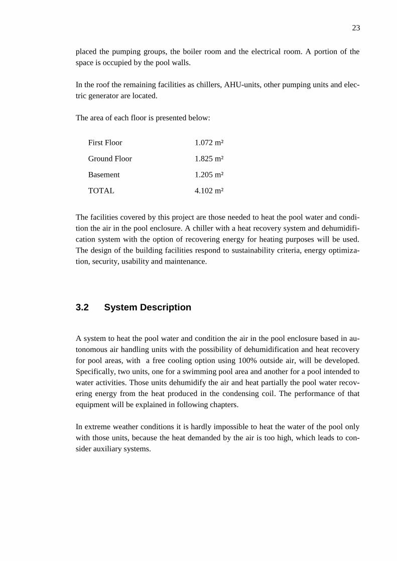
The area of each floor is presented below:
The facilities covered by this project are those needed to heat the pool water and condi-
tion the air in the pool enclosure. A chiller with a heat recovery system and dehumidifi-
cation system with the option of recovering energy for heating purposes will be used.
The design of the building facilities respond to sustainability criteria, energy optimiza-
tion, security, usability and maintenance.
3.2 System Description
A system to heat the pool water and condition the air in the pool enclosure based in au-
tonomous air handling units with the possibility of dehumidification and heat recovery
for pool areas, with a free cooling option using 100% outside air, will be developed.
Specifically, two units, one for a swimming pool area and another for a pool intended to
water activities. Those units dehumidify the air and heat partially the pool water recov-
ering energy from the heat produced in the condensing coil. The performance of that
equipment will be explained in following chapters.
In extreme weather conditions it is hardly impossible to heat the water of the pool only
with those units, because the heat demanded by the air is too high, which leads to con-
sider auxiliary systems.
First Floor 1.072 m²
Ground Floor 1.825 m²
Basement 1.205 m²
TOTAL 4.102 m²
24
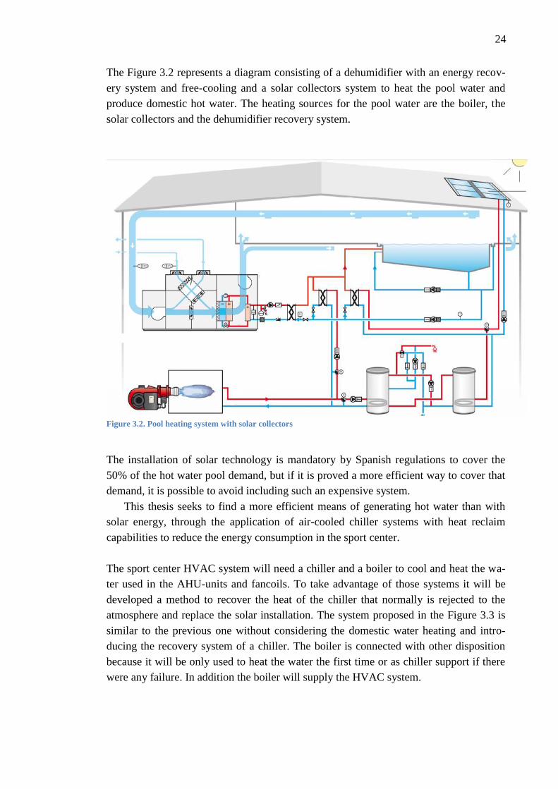
The Figure 3.2 represents a diagram consisting of a dehumidifier with an energy recov-
ery system and free-cooling and a solar collectors system to heat the pool water and
produce domestic hot water. The heating sources for the pool water are the boiler, the
solar collectors and the dehumidifier recovery system.
Figure 3.2. Pool heating system with solar collectors
The installation of solar technology is mandatory by Spanish regulations to cover the
50% of the hot water pool demand, but if it is proved a more efficient way to cover that
demand, it is possible to avoid including such an expensive system.
This thesis seeks to find a more efficient means of generating hot water than with
solar energy, through the application of air-cooled chiller systems with heat reclaim
capabilities to reduce the energy consumption in the sport center.
The sport center HVAC system will need a chiller and a boiler to cool and heat the wa-
ter used in the AHU-units and fancoils. To take advantage of those systems it will be
developed a method to recover the heat of the chiller that normally is rejected to the
atmosphere and replace the solar installation. The system proposed in the Figure 3.3 is
similar to the previous one without considering the domestic water heating and intro-
ducing the recovery system of a chiller. The boiler is connected with other disposition
because it will be only used to heat the water the first time or as chiller support if there
were any failure. In addition the boiler will supply the HVAC system.
25
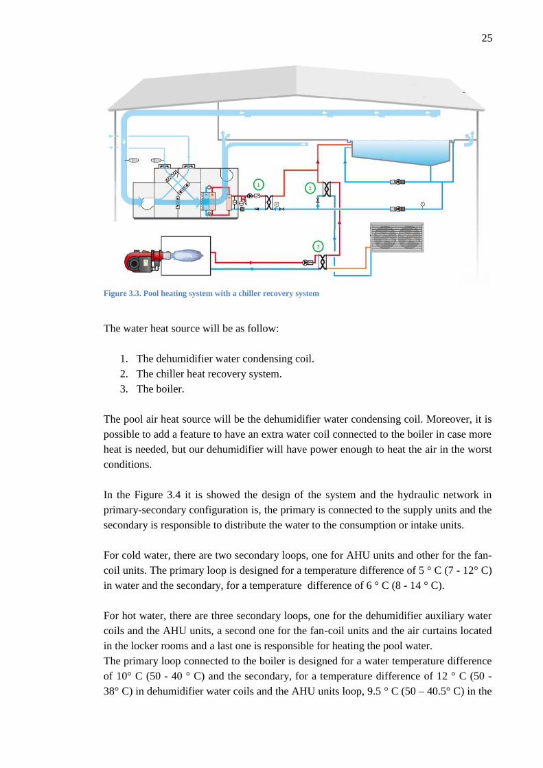
Figure 3.3. Pool heating system with a chiller recovery system
The water heat source will be as follow:
1. The dehumidifier water condensing coil.
2. The chiller heat recovery system.
3. The boiler.
The pool air heat source will be the dehumidifier water condensing coil. Moreover, it is
possible to add a feature to have an extra water coil connected to the boiler in case more
heat is needed, but our dehumidifier will have power enough to heat the air in the worst
conditions.
In the Figure 3.4 it is showed the design of the system and the hydraulic network in
primary-secondary configuration is, the primary is connected to the supply units and the
secondary is responsible to distribute the water to the consumption or intake units.
For cold water, there are two secondary loops, one for AHU units and other for the fan-
coil units. The primary loop is designed for a temperature difference of 5 ° C (7 - 12° C)
in water and the secondary, for a temperature difference of 6 ° C (8 - 14 ° C).
For hot water, there are three secondary loops, one for the dehumidifier auxiliary water
coils and the AHU units, a second one for the fan-coil units and the air curtains located
in the locker rooms and a last one is responsible for heating the pool water.
The primary loop connected to the boiler is designed for a water temperature difference
of 10° C (50 - 40 ° C) and the secondary, for a temperature difference of 12 ° C (50 -
38° C) in dehumidifier water coils and the AHU units loop, 9.5 ° C (50 – 40.5° C) in the
26
fan-coil units loop and 8 ° C (50 - 42 ° C) in the loops responsible for heating the pool
water.
The heat recovery system is disposed in a primary-secondary configuration as well, with
the chiller condenser side as the starting point of the primary loop and a heat exchange
as an extra source of energy for the pool water in the secondary one.
For heating the pools water, the energy recovery system of the chiller is used as the first
source. In case of not having enough energy or failure, a boiler would work as support
unit, besides it has been mentioned that the pool water is pre-heated from the dehumidi-
fier recovery system.
The division between the primary and secondary loops is done by implanting a separa-
tor manifold dimensioned to achieve a very low water flow rate in order to avoid inter-
ference between the circulation pumps of the two loops.
If is not established a right balancing of the system, this will consequence in unequal
distribution of the flow and there will be a surplus effect in some of the components so
that will not be ensured a correct heating/chilling in all parts of the installation. For that
reason the distribution of the water lines has direct return, provided with the necessary
balancing valves in each of the line to ensure the correct distribution of the flow in the
system. In addition, each line has its own stopcock and partial drain tap to allow the line
isolation because of maintenance needs or operating conditions of the building.
In a first stage the energy loss in the pool enclosure and the dehumidification needs will
be calculated to select a dehumidifier system.
In a second stage, the energy loss through the building will be calculated with computer
software, to know the power required by the chiller and the boiler. Although the HVAC
system will not be study, it is indispensable this calculation to know the recovery energy
that can be obtained from the chiller.
In the third stage the system equipment will be selected, dehumidifiers, chiller, heat
exchangers, pumps and other hydraulic components.
In the last phase the selection of the components will be justified from an energy effi-
ciency view making a comparison with a solar system.

27
Figure 3.4. System diagram

28
3.3 Building energy demand
3.3.1 Heat loss of the pool
3.3.1.1 Calculation Assumptions and Data
Measurements: Considering the Sport centre drafts (Figure 3.5, Figure 3.6, Figure 3.7)
and measuring in the Autocad document, the Tables 3.1 and 3.2 resume the pool and the
enclosure dimensions:
Table 3.1. Pools dimensions
Table 3.2. Pool enclosures dimensions
The total volume of the pool enclosure is 3130 m3.
Figure 3.5. Section of the pool enclosure
Pool Water surface Area Width Depth Volume
Swimming pool 312,5 m2 12,5 m 1,2 m 375 m
3
Pool for activities 75 m2 6 m 1 m 75 m
3
Pool enclosure Wall Windows Roof LNC Floor Dividing Wall
Swimming pool 185 m2 79 m
2 609 m
2 541 m
2 148 m
2
Pool for activities 130 m2 11 m
2 230 m
2 232 m
2 105 m
2

29
Figure 3.6. Pool enclosure outside view
Figure 3.7. Pool floor view

30
Materials and Heat Thermal Transmittance: In the absence of material data in the
architectural project we will use the minimum values that the Spanish Building Code
allows for each enclosure part (Table 3.3).
Table 3.3. Thermal transmittance for different materials
Wall 0,66 W/ m2 K 0,57 kcal/h m
2 K
Windows 3,00 W/ m2 K 2,58 kcal/h m
2 K
Roof 0,38 W/ m2 K 0,33 kcal/h m
2 K
Floor 0,49 W/ m2 K 0,55 kcal/h m
2 K
Dividing Wall 0,86 W/ m2 K 0,74 kcal/h m
2 K
Temperature: According to the IT.1 RITE standard [4], the air temperature will remain
1 to 3°C above the temperature of the water temperature in the pool. Likewise, the rela-
tive humidity of the environment is always maintained below 65 % to preserve the for-
mation of condensation in enclosures. Although the maximum temperature of the air
enclosure by regulation is 30ºC, a temperature of 32ºC will be used in order to assure
the temperature needed after the supply air mix with the enclosure air.
Under these conditions of temperature and humidity of users comfort is assure. These
temperature and humidity conditions prevent swimmers feeling cold and limit the evap-
oration of the water surface in the pool.
Tabla 3.4. Pool Temperature and humidity conditions
Pool Water Temperature Air Temperature Relative
Humidity
Pool Enclo-
sure Volume
Swimming
pool
29 °C 32 °C 65% 3.130 m
3
Pool for
activities
30 °C 32 °C 65% 1.185 m
3
Weather Information: In order to fulfil the Spanish regulation, the UNE
100001:2001standard [13] will be used, which define the limit weather conditions for
projects. This document has been prepared by the AEN/CTN 100 technical committee.
As the system will be projected in Segovia, Salamanca the closest city with regulated
data, will be considered. The city is situated 1002 m above the sea level with latitude of
41 º.The following extreme weather conditions will be used (Table 3.5).

31
Table 3.5. Outside extreme weather conditions
Summer
Outside Temperature 32,4 °C
Outside Relative Humidity 36,5%
Winter
Water temperature supply 10ºC
Outside Temperature -6,3 ºC
Outside Relative Humidity 90%
Although extreme weather conditions are used in order to assure a good performance
through the whole year, in the table 3.6 the monthly temperature values are exposed.
Table 3.6. Monthly weather data
Pool occupancy rate and Start-up time assumptions: Based in a manufacturer speci-
fication for sport centre pools, 72 hours start-up time will be assumed. The occupancy
rate is shown below.
Month Temperature
Average ºC
Relative
Humidity
Average %
Water
Supply Tem-
perature
Average ºC
Number of
sunshine
hours
Incident Energy
kWh/ m2.month
January 4 76 4 248 49
February 6 72 5 252 68
March 10 65 7 279 115
April 12 66 9 285 153
May 15 63 10 294 175
June 20 57 11 285 188
July 24 49 12 294 221
August 23 57 11 294 214
September 20 50 10 270 156
October 14 68 9 279 98
November 9 75 7 240 56
December 5 78 4 232 43

32
- 4 h with 0.2 swimmers/m2.h
- 5 h with 0.15 swimmers/m2.h
- 6 h with 0.1 swimmers/m2.h
- 9 h with 0 swimmers/m2.h
3.3.1.2 Heat loss of the pools
The heat loss of the pools and their enclosure can be summarized in the Table 3.7 and
Table 3.8:
Table 3.7. Heat loss of the pools
Water Heat Loss Swimming Pool Pool for activities
Evaporation 40736 W 12351 W
Radiation 2640 W 650 W
Convection -845 W -118 W
Water heating 8630 W 1817 W
Conduction 8871 W 2598 W
Table 3.8. Heat loss of the enclosure
Enclosure Heat Loss Swimming Pool Pool for activities
Conduction 27620 W 10620 W
Air heating 33230 W 7980 W
Total 60850 W 18600 W
Figure 3.8. Share of heating losses

33
3.3.2 Building Load Calculations
Every engineer needs to have handy empirical data for calculating approximates loads
and equipment sizes through the early stages of the design process. However, in a more
developed phase is essential to make detailed and well-documented load calculations,
because are the key for a right equipment selection, duct or pipes design, and psychro-
metric analysis.
3.3.2.1 Design Criteria
Indoor design conditions are determined by comfort or process requirements. According
to the RITE (IT 1.1.4.1.2) [11], the following design temperature limits for occupied
zones are considered in calculating the project loads.
- Winter: 22 ° C, with an operating temperature between 21 ° C and 23 ° C
and a relative humidity between 40%-50%. In extreme weather condi-
tions and start-up periods should not be considered relative humidity
values of less than 35%.
- Summer: 24 ° C, with an operating temperature between 23 ° and 25 ° C
and a relative humidity between 45-60 %.
These two values of temperature must be maintained within the occupied zone. The
occupied zone is considered as the volume intended for human occupancy and is de-
fined by vertical planes parallel to the walls of the room and a horizontal plane that de-
limits the height of the floor. The distances of these planes from the inner surfaces of
the room are as follows:
- Lower limit from ground: 5 cm.
- Upper limit from the ground: 180 cm.
- Outer walls with windows or doors: 100 cm.
- Inner walls and outer walls without windows: 50 cm.
- Doors and transit zones: 100 cm.
It will not be considered as occupied zones, those that may have significant temperature
variations from the average or may have significant airflow rates around people , as
transit areas or areas near doors frequently used, zones close to any unit which impulse
air or with high heat production. Outside design conditions are determined from regu-
lated data for the specific location, based on weather records.

34
Once the criteria is defined and the HAP from Carrier method is chosen the load calcu-
lations are a matter of accurately determining areas, internal load densities such as peo-
ple, process loads, lighting and any unusual conditions.
Depending on the zone orientation peak loads will vary with the hour and season. In
order to size the air-handling equipment, HAP calculates the loads in accordance with
the peak annual load in that zone thanks to the database incorporated. Some specific
requirements will be apply in the rooms with more activity following RITE specifica-
cions [4].
- Activity Rooms
o People load:
Qsensible = 154 W/person
Qlatent = 271 W/person
Ocuppancy rate: 3 m2/person
o Outdoor air flow rate per person:
Qextair= 28,8 m3/h/person
o Lighthing and eletrical devices:
Lighthing (10W/ m2).
3000W Audio equipment.
- Spinning Room
o People load:
Qsensible = 308 W/person
Qlatent = 435 W/person
Ocuppancy rate: Number of bicycles 2 m2/person
o Outdoor air flow rate per person:
Qextair = 28,8 m3/h/person
o Lighthing and eletrical devices:
Lighthing (10W/ m2).
3000W Audio equipment.
- Fitness Room
o People load:
Qsensible = 154 W/per
Qlatent = 271 W/per
o Ocuppancy rate: Workout equipment 5,3 m2/per
o Outdoor air flow rate per person:
Qaext= 28,8 m3/h/per
o Lighthing and eletrical devices:
Lighthing (10W/ m2).
1200W Audio equipment.

35
In order to dothe load calculations ,it will be used the space distribution specified in Appen-
dix C and considering the occupied zones which are expected to be climatized.
In the summary table 3.30 it is shown the output data provided by the HAP Carrier’s
software for all the spaces. With the input data the software calculates the window and
solar loads, the wall, windows, doors and roof/floor transmission loss or internal loads
as lighting, electric equipment and people. The return fan, ventilation and supply fan
loads are estimated in accordance with the ventilation requirements.
A total cooling load of 217 kW is calculated, it will be considered 225 kW in order to
select the chiller, assuming an additional 5% because of the AHU-units and fancoils
power installed.
The total heating load is 161 kW, it will be considered 170 kW in order to select the
boiler because of the AHU-units and fancoils power installed should be higher.
Table 3.9. Heating and cooling loads of spaces
Sensible Cooling Latent Cooling Sensible Heating Latent Heating
Zone 1 15808 W 11913 W 5979 W 5587 W
Zone 2 33245 W 17610 W 22259 W 20039 W
Zone 3 12868 W 7185 W 4787 W 2760 W
Zone 4 49811 W 22502 W 11979 W 8102 W
Zone 5 15815 W 8464 W 7456 W 2997 W
Zone 6 1801 W 306 W 1050 W 0 W
Zone 7 1981 W 284 W 2088 W 0 W
Zone 8 239 W 120 W 270 W 0 W
Zone 9 239 W 120 W 270 W 0 W
Zone 10 461 W 67 W 289 W 0 W
Zone 11 876 W 119 W 283 W 0 W
Zone 12 2945 W 274 W 1829 W 0 W
Zone 12+ 1483 W 209 W 1496 W 0 W
Zone 13 1335 W 179 W 266 W 0 W
Zone 14 3053 W 0 W 1278 W 0 W
Zone 15 322 W 97 W 715 W 0 W
Zone 16 2283 W 502 W 2675 W 0 W
Zone 17 1655 W 337 W 908 W 0 W
Zone 18 - - 22142 W 0 W
Zone 19 - - 20733 W 0 W
Zone 20 - - 12754 W 0 W
TOTAL 146220 W 70288 W 121506 W 39485 W

36
3.4 Swimming Pool Dehumidification System
In accordance with the Bernier equation [5] the evaporated mass flow per hour defines
the dehumidification capacity needed by the system (Table 3.31).
Table 3.9. Dehumidification needs
Swimming Pool Pool for activities
Dehumidification needs 86,45 kg/h 25,50 kg/h
In order to fulfill our dehumidification needs, a software developed by Sedical, a lead-
ing company in energy saving, is used to do a more accurate selection, taking into ac-
count other factors given by the experience of this company in the field to guarantee top
levels of comfort all year round.
Taking into consideration the specific requirements of the project, a system that dehu-
midify, cool, heat and renew the ambient air whilst simultaneously heating the pool wa-
ter free of charge is chosen.
The Dry-Pool dehumidifier is an air and/or water cooled machine with hermetic scroll
compressors and R410A refrigerant gas that has been designed to meet all the necessi-
ties of the swimming pool environment. Thanks to the use of the refrigerant circuit, the
air treatment energy loads are drastically reduced. An auxiliary hot water coil is in-
stalled after the condensing coil, that is supplied with a motor-driven three-way valve
and balancing valve on the bypass branch completely managed by a microprocessor.
Figure 3.9. Dehumidifier diagrams
37
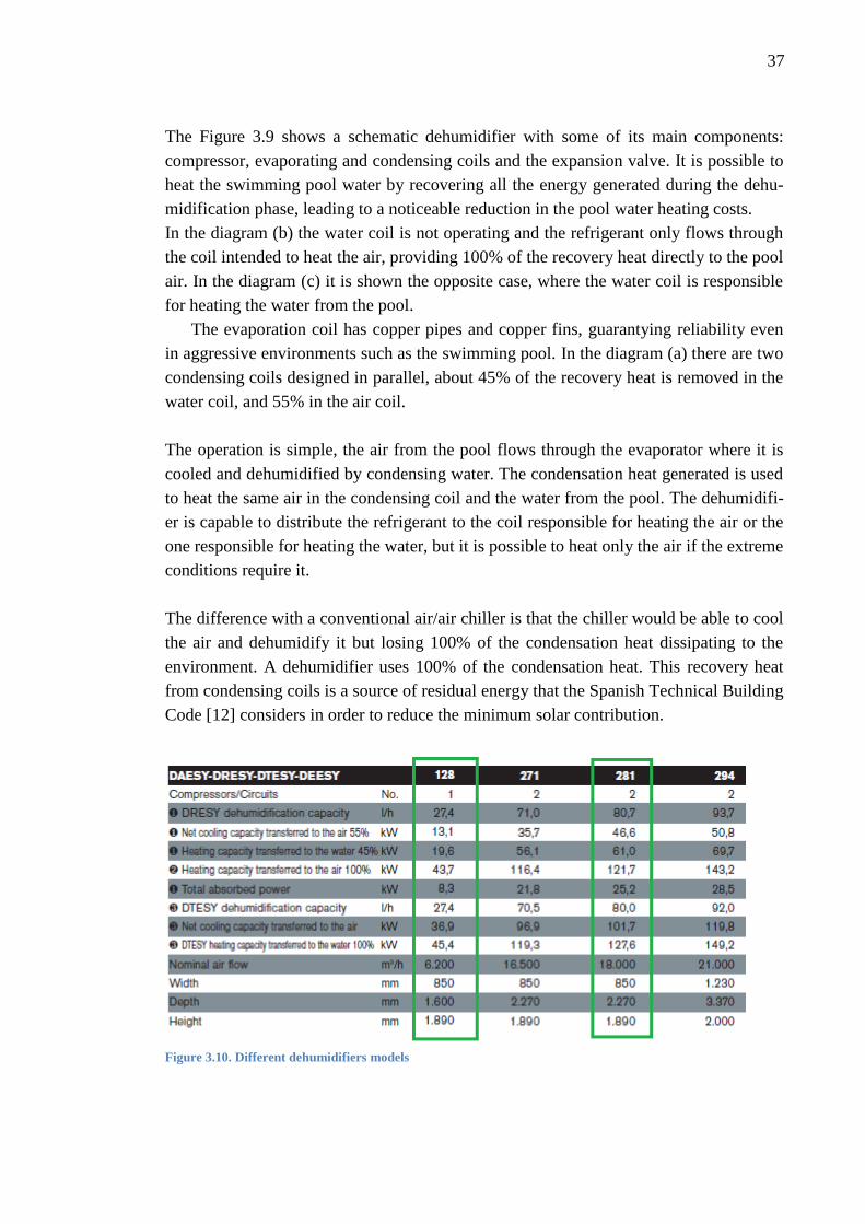
The Figure 3.9 shows a schematic dehumidifier with some of its main components:
compressor, evaporating and condensing coils and the expansion valve. It is possible to
heat the swimming pool water by recovering all the energy generated during the dehu-
midification phase, leading to a noticeable reduction in the pool water heating costs.
In the diagram (b) the water coil is not operating and the refrigerant only flows through
the coil intended to heat the air, providing 100% of the recovery heat directly to the pool
air. In the diagram (c) it is shown the opposite case, where the water coil is responsible
for heating the water from the pool.
The evaporation coil has copper pipes and copper fins, guarantying reliability even
in aggressive environments such as the swimming pool. In the diagram (a) there are two
condensing coils designed in parallel, about 45% of the recovery heat is removed in the
water coil, and 55% in the air coil.
The operation is simple, the air from the pool flows through the evaporator where it is
cooled and dehumidified by condensing water. The condensation heat generated is used
to heat the same air in the condensing coil and the water from the pool. The dehumidifi-
er is capable to distribute the refrigerant to the coil responsible for heating the air or the
one responsible for heating the water, but it is possible to heat only the air if the extreme
conditions require it.
The difference with a conventional air/air chiller is that the chiller would be able to cool
the air and dehumidify it but losing 100% of the condensation heat dissipating to the
environment. A dehumidifier uses 100% of the condensation heat. This recovery heat
from condensing coils is a source of residual energy that the Spanish Technical Building
Code [12] considers in order to reduce the minimum solar contribution.
Figure 3.10. Different dehumidifiers models

38
The air conditioning of a closed pool has very different requirements from those of a
typical system for residential or commercial utilities. When selecting reasonable operat-
ing conditions for swimming pool environments, it is important to find the right balance
between the comfort of the swimming pool users and the energy costs involved in run-
ning the system.
In order to minimize the water evaporation rate and thus the system running costs, it is
always necessary to have an air temperature that is higher than the temperature of the
water in the pool.
The greater the temperatures difference between air and water, the lower the evapora-
tion rate. Obviously, for reasons of comfort, this difference cannot be excessive and the
manufacturer usually advises keeping it at a ∆t of 2 /3 °C.
The values typically used for this type of system are listed below:
• Ambient air temperature: 27÷32°C
• Ambient air relative humidity: 60÷70%
• Pool water temperature: 26 to 30°C
In figure 3.10 it is shown the different dehumidifier models (model 128, model 271, etc)
with different specifications. Following the guidelines from Sedical, the model DRESY
281 [15] is selected for the swimming pool and DRESY 128 [15] for the pool of activi-
ties.
Although the dehumidification capacity is a little smaller than the dehumidification
needs, Sedical recommend that selection because it will be the maximum rate only in a
small period of time in the warmest months.
Table 3.10. Energy needs and dehumidifier specification comparison
Enclosure and Water Energy Summary
Dehumidification needs 86,45 kg/h
Start-up Power 238,48 kW
Water Average Loss 60,03 kW
Water Peak Loss 67,83 kW
Enclosure Loss 60,85 kW
Dehumidification System: DRESY 281
Dehumidification Capacity 80,7 kg/h
Air Flow rate (32 ºC; 65%; 0,89 m3/ Kg dry air) 18000m
3/h
Heating Capacity transferred to the water 61,0 kW
Heating Capacity transferred to the air 67,7 kW
Refrigeration Capacity in the Evaporation Coil 101,5 kW
39
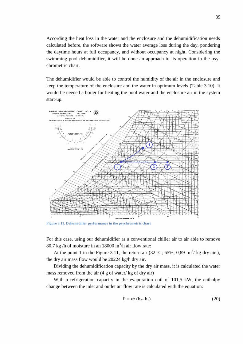
According the heat loss in the water and the enclosure and the dehumidification needs
calculated before, the software shows the water average loss during the day, pondering
the daytime hours at full occupancy, and without occupancy at night. Considering the
swimming pool dehumidifier, it will be done an approach to its operation in the psy-
chrometric chart.
The dehumidifier would be able to control the humidity of the air in the enclosure and
keep the temperature of the enclosure and the water in optimum levels (Table 3.10). It
would be needed a boiler for heating the pool water and the enclosure air in the system
start-up.
Figure 3.11. Dehumidifier performance in the psychrometric chart
For this case, using our dehumidifier as a conventional chiller air to air able to remove
80,7 kg /h of moisture in an 18000 m3/h air flow rate:
At the point 1 in the Figure 3.11, the return air (32 ºC; 65%; 0,89 m3/ kg dry air ),
the dry air mass flow would be 20224 kg/h dry air.
Dividing the dehumidification capacity by the dry air mass, it is calculated the water
mass removed from the air (4 g of water/ kg of dry air)
With a refrigeration capacity in the evaporation coil of 101,5 kW, the enthalpy
change between the inlet and outlet air flow rate is calculated with the equation:
P = (h2- h1) (20)

40
Table 3.11. Thermodynamic properties of points 1 and 2
The dehumidifier works as a chiller air /air with the outlet flow rate at point 2 and 101,5
kW refrigeration capacity.
In the psychrometric chart is known that the horizontal component of the condition line
is the change in sensible heat while the vertical component represents the change in la-
tent heat.
The sensible heat in the cooling 1-2 is 44,94 kW and the remaining heat is used to de-
humidify from 19,37
to 15,37
The Dresy dehumidifier [15] also transfers 67,7 kW to the pool air turning the point 2
into the point 3, and transfers 61 kW to the pool water. Moreover, it can operates, if
necessary, transferring all the heat to the air, in which case the assigned heat would be
128,7 kW and the point 3 would become 3’.
Clearly the dehumidifier takes advantage of this residual energy source and is designed
to recover that heat (Figure 3.12). It does not make sense to heat the water of the pool
with solar energy and dissipate the heat produced in the dehumidification process.
In the calculations above, it was considered that the dehumidifier inlet air is completely
returned from the pool enclosure at 32 º C and 65%, but the reality is that the intake air
is a mixture of indoor air and outdoor air with an approximate ratio of 80/20%, as it is
showed in the picture, and this causes the inlet air is 1 to 3 ° C lower than the air from
the enclosure. The dehumidifier sends it back to the pool dehumidified and at a tem-
perature about 3 ° C higher than the inlet air. In order to balance out the conduction
losses in windows and walls it was selected 32ºC as reference to maintain the tempera-
ture in the pool not lower than 30 ºC.
Point
1
Data Psychrometric Chart
32 ºC 65% 19,37
64,32
Point
2 15,37
62,92
24 ºC 78%

41
Figure 3.12. Dehumidifier performance
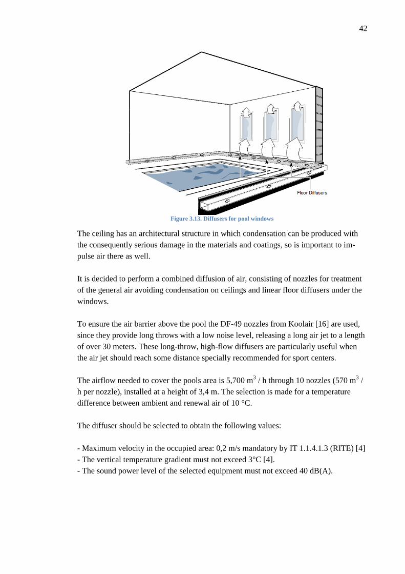
3.5 Air diffusion in the pool enclosure
Distribute the air in the pool enclosure is very complex due to several factors:
The pool enclosure is more than 4 meters high with a variable height, so a system that
discharges air jets at high speed horizontally to create a barrier to prevent air stratifica-
tion is needed. This is crucial to maintain the warm air close to the occupied zone and
avoid an accumulation in higher zones.
The pool enclosure is quite big and the air can only be dispersed through the walls be-
cause, for architectural reasons, the ceiling cannot hold a duct structure. It is necessary
to disperse the supply air far enough to cover the pool surface.
Since exterior windows are the main condensation concern, the supply air must be fo-
cused there, as it is shown in Figure 3.13. The warm air from the dehumidifier will keep
the window surface temperature above the dew point to guarantee no condensation
problems.
42
Figure 3.13. Diffusers for pool windows
The ceiling has an architectural structure in which condensation can be produced with
the consequently serious damage in the materials and coatings, so is important to im-
pulse air there as well.
It is decided to perform a combined diffusion of air, consisting of nozzles for treatment
of the general air avoiding condensation on ceilings and linear floor diffusers under the
windows.
To ensure the air barrier above the pool the DF-49 nozzles from Koolair [16] are used,
since they provide long throws with a low noise level, releasing a long air jet to a length
of over 30 meters. These long-throw, high-flow diffusers are particularly useful when
the air jet should reach some distance specially recommended for sport centers.
The airflow needed to cover the pools area is 5,700 m3 / h through 10 nozzles (570 m
3 /
h per nozzle), installed at a height of 3,4 m. The selection is made for a temperature
difference between ambient and renewal air of 10 °C.
The diffuser should be selected to obtain the following values:
- Maximum velocity in the occupied area: 0,2 m/s mandatory by IT 1.1.4.1.3 (RITE) [4]
- The vertical temperature gradient must not exceed 3°C [4].
- The sound power level of the selected equipment must not exceed 40 dB(A).

43
The selection is done using the catalogue charts provided by the manufacturer [16] and
the initial data (Table 3.12).
Table 3.12. Initial diffusion data
Reach distance 11 m
Height from floor 4 m
Nozzle flow 570 m3 / h 570 m3 / h
Supply Temperature 39° C
Room Temperature 29° C
Difference of temperatures ΔT 10° C
Height of occupied area 2 m
The sound power limit of 40 dB(A) must not be exceeded, so the size 10 is preselected
with the quick selection table and that maximum value.
Using this size for 570 m3 / h, the pressure drop and real sound power level is deter-
mined with the chart (Figure 1 Appendix D).
Using the velocity of the air jet for the throw chart (Figure 2 Appendix D) with an sup-
ply angle of -4°, the throw and velocity are determined.
The impact point under isothermal conditions is calculated with a simple trigonometric
relation. With the temperature difference, the vertical deviation caused by a temperature
difference between the supply and ambient air is view in the chart (Figure 3.16) and the
impact point height from the floor of the air jets is calculated as the difference between
the height at isothermal conditions and the deviation.
With the ratio between air flow velocities chart (Figure 3 Appendix D) the air velocity
in the occupied area is determined.
The temperature of the air jet at its inlet in the occupied zone is determined by the chart
(Figure 4 Appendix D) and the induction rate, quotient between the air flow for a throw
X and the air flow supplied in the zone, determined by the chart (Figure 5 Appendix D).
The results of the diffusion study are shown in the table 3.13 below. According to the
data obtained, it is ensured that the entire surface pool is covered, without any risk of
condensation in the ceiling structure and average speeds in occupied area are within the
limits of the comfort conditions. The air jet is represented in the Figure 3.14.

44
Table 3.13. Diffusion results summary
Effective supply velocity 12,5 m/s
Size 10
Total pressure drop 89 Pa
Sound power level 38 dB
Velocity of the jets at throw X 0,78 m/s
Deviation of the air jet 1,3
Velocity of the jets in the occupied area 0,08 m/s
Induction rate 30,9
Temperature in occupied area 29,5 ºC
Figure 3.14. Throw air graphic
3.6 Airduct Design
The purpose of a duct system is to carry air from the AHU units or in this case a dehu-
midifier to the zone to be conditioned. The duct is the static component of the installa-
tion through which air flows within the building.
To fulfill this task in a practical way, the system is designed satisfying some require-
ments as fitting in the available space, low friction loss, velocity limitations to avoid
high noise levels, heat losses and gains, fire and smoke control and balancing [20].
It must be considered these practical design criteria to avoid an incorrect operation,
a system with lack of sound attenuation or high air velocity can produce excessive noise
levels, high friction loss leads to an inadequate air flow rate at the units producing dis-
comfort or inefficiencies in the equipment.
The space available in ceiling plenums or obstructions such as walls or beams for the
supply and return air ducts, and their appearance usually determines the system design
regardless if it is not the best size from a cost or friction loss perspective. In addition,
45
there are other building system components that interact with the duct network, so coor-
dination is necessary in order to avoid problems in the assembly.
In the swimming pool ceiling there is not plenum and the ductwork has to be exposed
and attached some way to the ceiling. For this case, rectangular ductwork is ideal be-
cause is constructed to give the appearance of a beam, furthermore rectangular duct-
work is probably the most economical design for this application.
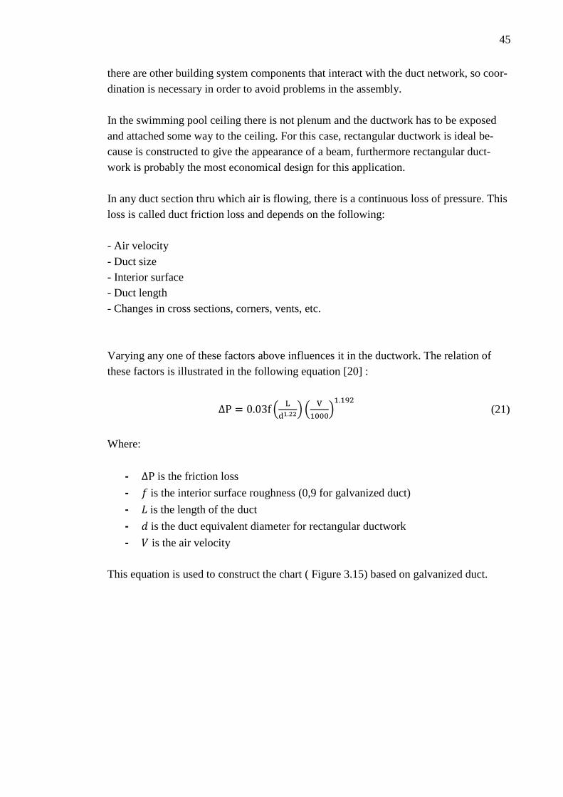
In any duct section thru which air is flowing, there is a continuous loss of pressure. This
loss is called duct friction loss and depends on the following:
- Air velocity
- Duct size
- Interior surface
- Duct length
- Changes in cross sections, corners, vents, etc.
Varying any one of these factors above influences it in the ductwork. The relation of
these factors is illustrated in the following equation [20] :
(
) (
)
(21)
Where:
- is the friction loss
- is the interior surface roughness (0,9 for galvanized duct)
- is the length of the duct
- is the duct equivalent diameter for rectangular ductwork
- is the air velocity
This equation is used to construct the chart ( Figure 3.15) based on galvanized duct.

46
Figure 3.15. Friction loss for round duct
The usual procedure for designing a duct system is to keep a simple layout with a sym-
metrical position. It can be followed different methods to design a proper low velocity
air system; velocity reduction, equal friction or static regain [4].
The equal friction method is the most extended and recommended, this method employs
the same friction loss per foot of length for the entire system. The usual procedure is to
choose an initial value for the air velocity in the main duct, smaller than the maximum
recommended in the table 3.14.
Table 3.14. Recommended maximum duct velocities (m/s) [4]

47
The equal friction method does not satisfy the design criteria of uniform pressure at all
branches and air terminals. For this reason, it is necessary to install a splitter dampers to
regulate the flow to the branch or diffusor with a properly control device to regulate at
each terminal for air distribution.
In order to design the ductwork, the following variables and values will be taken into
consideration:
- The maximum supply air quantity required for removed the moisture in the pool
and climatize the enclosure.
- The design velocity plays an important role in a low velocity system in order to
avoid noises and usually is based on experience. A very high velocity results in
smaller ducts and lower duct material cost but it requires a higher operating cost
and bigger fan motors. A velocity of 9 m/s is selected with sound level as limit-
ing factor in the duct section from the fan to the first branch. Then the friction
loss is calculated and kept as reference throughout the system.
- The friction rate will not exceed 1,08Pa/m (0,11 mmca/m), but as the ducts are
limited by the shafts dimensions and space available the friction loss will be
maintained within limits. Unlike the equal friction method, with this method a
maximum value is defined but if the velocity is to high the duct size is increased
to avoid excessive noise in the ducts close to the diffusers or the pool enclosure.
A splinter damper is installed previously to the diffusers to regulate the flow and
equilibrate the system.
The calculation of the duct dimensions are represented in the tables 3.15 and 3.16 where
it can be appreciated that the friction loss is maintained within the limit and the velocity
of the air close to the diffusers or pool enclosure is conserved below 5m/s.
Figure 3.16. Diffusion and return grills disposal

48
The air return duct pulls air back through plenums located in the wall extracting the air
from the pool to the dehumidifiers. The diffusers under the windows are disposed as
shown in the Figure 3.22.
Table 3.15. Dimensions of supply and return ducts for the swimming pool
Table 3.16. Dimensions of supply and return ducts for the pool of activities
In the figures 3.17 and 3.18 is represented the ductwork layout through the basement
where the dehumidifiers are located, and the pool enclosure. Through the blue and or-
ange ducts the exhaust and supply air is carried to the dehumidifiers. Those ducts are
communicated to the roof by a shaft.

49
Figure 3.17. Basement air-duct distribution

50
Figure 3.18. Pool enclosure duct distribution and diffusors

51
3.7 Chiller
The AHU-units and fancoils responsible for climatizing the sport center require a ma-
chine for the production of chilled water. The heat collected by the chiller during cool-
ing is rejected through the condenser, however, if there is a simultaneous need for heat,
then this heat can be recovered and utilized rather than being rejected outdoor.
The load calculation was intended to select a chiller with an exhaust air recovery sys-
tem. Once selected, with the data provided by the manufacturer it is essential to find out
the amount of energy that is capable of recover. The exhaust heat can be recovered to
heat the pool water and for this reason the scope of the selection will be to fulfill the
regulations and design the hydraulic recover pipelines.
Figure 3.19. Chiller
A high energy efficiency chiller with axial fans, Scroll compressors and plate type ex-
changers installed outdoors and air-cooled will be used (Figure 3.19). With the results
obtained through the load calculation and the manufacturer catalogue [17] it is selected
a machine with a cooling capacity of 241 kW to cover the energy needs of the building
(Table 3.17).
Table 3.17. Chiller data sheet
Chiller
Model AIRLAN NRL 0900
Refrigerant R410
Cooling Capacity (kW) 241
Total power input (kW) 81,7
Heat recovery power (kW) 318
Fans 4 (Axial)
Dimensions (mm) 3400x2200x2450
Weight (kg) 2265
Compressors Scroll
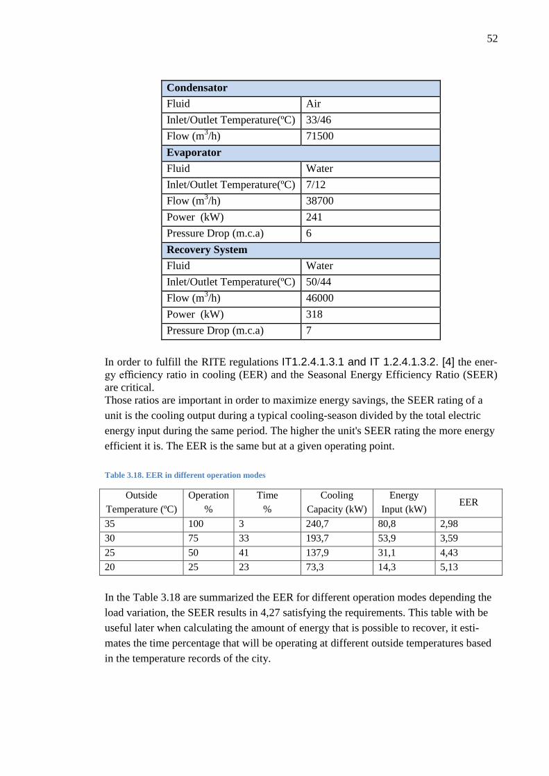
52
Condensator
Fluid Air
Inlet/Outlet Temperature(ºC) 33/46
Flow (m3/h) 71500
Evaporator
Fluid Water
Inlet/Outlet Temperature(ºC) 7/12
Flow (m3/h) 38700
Power (kW) 241
Pressure Drop (m.c.a) 6
Recovery System
Fluid Water
Inlet/Outlet Temperature(ºC) 50/44
Flow (m3/h) 46000
Power (kW) 318
Pressure Drop (m.c.a) 7
In order to fulfill the RITE regulations IT1.2.4.1.3.1 and IT 1.2.4.1.3.2. [4] the ener-
gy efficiency ratio in cooling (EER) and the Seasonal Energy Efficiency Ratio (SEER)
are critical. Those ratios are important in order to maximize energy savings, the SEER rating of a
unit is the cooling output during a typical cooling-season divided by the total electric
energy input during the same period. The higher the unit's SEER rating the more energy
efficient it is. The EER is the same but at a given operating point.
Table 3.18. EER in different operation modes
Outside
Temperature (ºC)
Operation
%
Time
%
Cooling
Capacity (kW)
Energy
Input (kW) EER
35 100 3 240,7 80,8 2,98
30 75 33 193,7 53,9 3,59
25 50 41 137,9 31,1 4,43
20 25 23 73,3 14,3 5,13
In the Table 3.18 are summarized the EER for different operation modes depending the
load variation, the SEER results in 4,27 satisfying the requirements. This table with be
useful later when calculating the amount of energy that is possible to recover, it esti-
mates the time percentage that will be operating at different outside temperatures based
in the temperature records of the city.

53
The Table 3.17 shows that the chiller is able to produce 318 kW to heat the water with a
100% performance and the water flow is 46000 m3/h with a 44-50 temperature differ-
ence. It will be assumed the chiller operating at 225kW that is the cooling load calculat-
ed and the recovering system at 300kW.
Figure 3.20. Chiller hydraulic system
In the Figure 3.20 is represented the hydraulic system with the appropriated vibration
isolators, pressure gauges, thermometers, valves and a buffer tank to have available hot
water in case the chiller is not working simultaneously. The pink pipelines will be con-
nected to our system and the blue ones are responsible for the AHU-units or fancoils of
the building.
3.8 Boiler
A boiler to heat the water of the pool the first time at the start-up system and supply de
AHU-units and fancoils is required. A Condensing boiler with high efficiency, which
uses the waste heat in the flue gases pre-heating the inlet cold water is selected. The
difference with a conventional boiler is that this kind of boiler extracts additional heat
from the waste gases by condensing the water vapor, produce during the combustion, to
liquid, leaving the system via a drain, thus recovering its latent heat of vaporization.
Tabla 3.19. Power heating summary
Pools Water Pools Air Fancoils/AHU-units TOTAL
Power required (kW) 101 92 170 363

54
Considering the heating of the pools air and water and the building heating load, the
total power needed by the system is 363 kW, therefore a condensing boiler of 450 kW
is selected from Ygnis catalogue [18], which has models from 40 kW to 600 kW (Table
3.20). The pools water and air heating is considered because of the system start-up and
in case there were a failure. The dehumidifiers has an extra coil to heat the air if it is
necessary using water from the boiler.
Table 3.20. Condensing boiler technical sheet
Assuming a 50-40,5 ºC temperature difference in the water flow for the AHU-units, 50-
38 ºC for the fancoils and 50-42 ºC for the pool water heating pipeline the water flow is
determined. In the Figure 3.21 is shown the boiler connected to a separator manifold
dimensioned to achieve a very low water flow rate in order to avoid interference be-
tween the circulation pumps of the different loops, all the system with the appropriated
pressure gauges, thermometers, valves, collectors and pumps.

55
Figure 3.21. Condensing Boiler hydraulic diagram
3.9 Pumps
Centrifugal pumps are used in HVAC systems for circulation of chilled, hot, and con-
densing water in which the rotating action of the impeller generates a pressure which
forces the fluid through the pipelines.
In order to size the pumps of the system it is necessary to define:
- The flow rate of liquid
- The liquid density
- The system pressure drop at the design flow rate
Losses include pipe, fittings, valves, and equipment such as heat exchangers, boilers, or
chillers.
A software developed by Ebara [19], a pumps manufacturer, will be used to choose the
proper design operating point in the performance pump curve, analyzing different pump
curves to find the best efficiency and lowest power. The program calculates the pressure
drop in the line considering the length, diameter, valves, filters, fittings, elbows and
equipment. It is necessary to introduce the diameter of each valve and filter as well as
the equipment pressure drops supply by the manufacturers catalogues [19].

56
Table 3.21. Data input for pumps selection
Line Flow rate (l/h) Length
(m) Valves Elbows Filters Equipment
Boiler 35000 30 5 3 1 Boiler
Chiller 46000 70 6 20 1 Chiller
Pool water heating 9500 170 8 24 1 3 Heat Exchangers
Pool water heating 11000 160 11 20 1 Heat Exchanger
Pool for activities 9400 30 8 12 1 Heat Exchanger
Dehumidifier
Swimming pool 23500 30 8 12 1 Heat Exchanger
Dehumidifier
The table 3.22 summarize the pumps used in the system ant their characteristics. The
pump performance curves are presented in the appendix A.
Table 3.22. Pump selection summary
Model
Capacity
(m3/h)
Pressure
drop
(kPa)
Motor
power
(kW)
Nominal
Speed
(r.p.m)
Frecuency
(Hz)
Discharge
Diammeter
(mm)
Pump
1
ELD 80-
160 46 78 1,5 1450 50 116
Pump
2
ELD65-
160 35 59 1,1 1450 50 116
Pump
3
ELD 50-
250 9,5 186 2,2 1450 50 116
Pump
4
EL 50-
200 9,4 107 1,1 1450 50 116
Pump
5
El 65-
200 23,5 117 1,5 1450 50 116
Pump
6
ELD 50-
250 11 215 2,2 1450 50 116
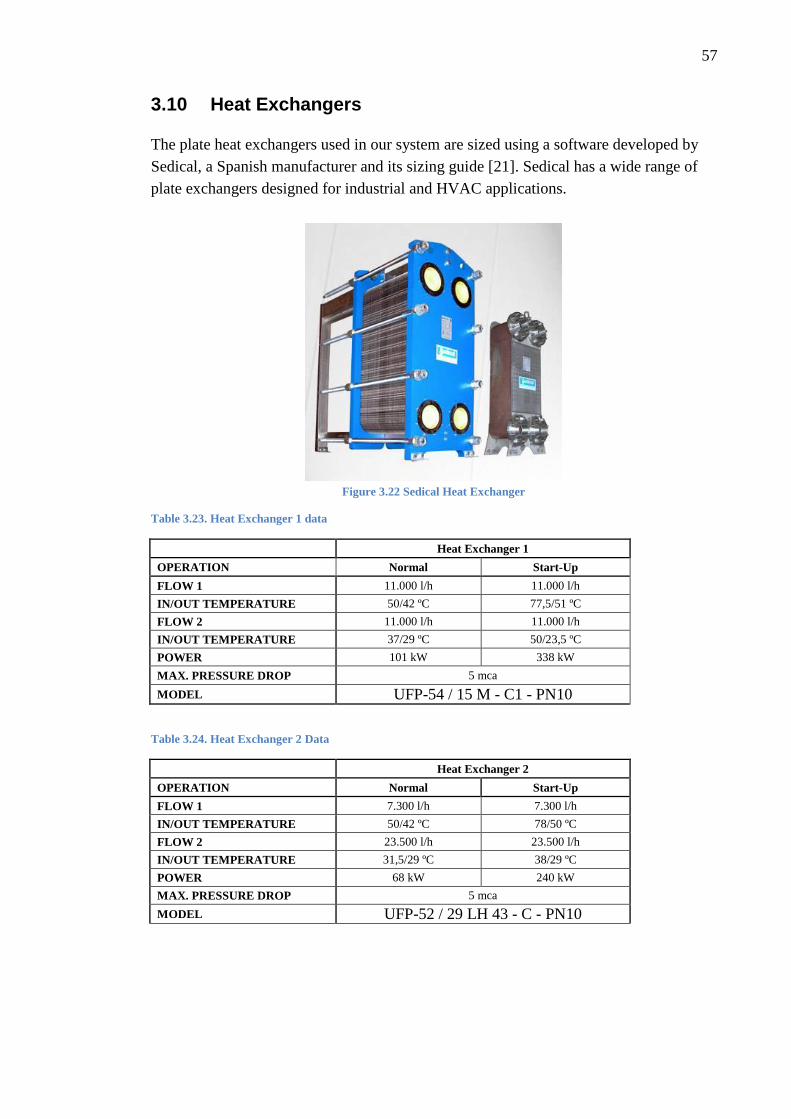
57
3.10 Heat Exchangers
The plate heat exchangers used in our system are sized using a software developed by
Sedical, a Spanish manufacturer and its sizing guide [21]. Sedical has a wide range of
plate exchangers designed for industrial and HVAC applications.
Figure 3.22 Sedical Heat Exchanger
Table 3.23. Heat Exchanger 1 data
Heat Exchanger 1
OPERATION Normal Start-Up
FLOW 1 11.000 l/h 11.000 l/h
IN/OUT TEMPERATURE 50/42 ºC 77,5/51 ºC
FLOW 2 11.000 l/h 11.000 l/h
IN/OUT TEMPERATURE 37/29 ºC 50/23,5 ºC
POWER 101 kW 338 kW
MAX. PRESSURE DROP 5 mca
MODEL UFP-54 / 15 M - C1 - PN10
Table 3.24. Heat Exchanger 2 Data
Heat Exchanger 2
OPERATION Normal Start-Up
FLOW 1 7.300 l/h 7.300 l/h
IN/OUT TEMPERATURE 50/42 ºC 78/50 ºC
FLOW 2 23.500 l/h 23.500 l/h
IN/OUT TEMPERATURE 31,5/29 ºC 38/29 ºC
POWER 68 kW 240 kW
MAX. PRESSURE DROP 5 mca
MODEL UFP-52 / 29 LH 43 - C - PN10

58
Table 3.25. Heat Exchanger 3 Data
Heat Exchanger 3
OPERATION Normal Start-Up
FLOW 1 2.200 l/h 2.200 l/h
IN/OUT TEMPERATURE 50/42 ºC 78/56 ºC
FLOW 2 9.400 l/h 9.400 l/h
IN/OUT TEMPERATURE 32/30 ºC 35/30 ºC
POWER 20 kW 57 kW
MAX. PRESSURE DROP 5 mca
MODEL UFP-32 / 30 H - C - PN10
In the tables 3.23, 3.24 and 3.25 are disposed the Heat exchangers characteristics de-
signed based in the inlet/outlet temperature and the flow rate in the primary and second-
ary lines.
3.11 Final System Diagram
The system diagram with all the dimensions is shown in Figure 3.23. The chiller is lo-
cated on the roof, where the recovery system pipelines go down through a shaft to the
heat exchangers placed in the basement, close to the dehumidifiers. The heat recovered
is expected to contribute the DHW system used in the sport center, so an outlet and inlet
pipeline is done in advance.
The water pipelines from the pool are connected to the dehumidifier and the heat ex-
changer from the chill recovery system and the boiler is connected to that line with an-
other heat exchanger.
All the shutoff, balancing and two or three way valves are disposed to make easier the
dismantling and regulation in the network. The twin pumps are made of the same basic
components and hydraulic design as the single In-line pumps, but are comprises of two
pumps in one common casing incorporated with a non-return valve which prevents the
internal circulation in case only one pump is running or the other is dismounted for re-
pair.
Pressure gauges and thermometers are included to control the correct performance of
the system.

59
Figure 3.23. Final system diagram

60
4. COMPARATIVE WITH A SOLAR SYSTEM
The minimum solar contribution to heat swimming pools water is regulated by the RITE
IT 1.2.4.6.2 [4] which specifies that thermal installations for those purpose shall accom-
plish with the requirement set in the HE 4 "Minimum solar contribution to domestic or
pools hot water" section of the Technical Building Code.
According to the document, at least a 50% solar contribution of the annual energy de-
mand is required for heating the water. Therefore, a calculation with solar panels is per-
formed to cover 50% of the demand in Appendix B.
The result of the calculation for that specification, shows an annual output of 507891
kWh produced by solar collectors, with an annual heat demand of 1011610 kWh.
The RITE in its IT.1.2.2 instruction [4] establish the energy efficiency requirements. It
indicates that is possible to design and size heating alternative systems on condition that
the energy effiency is improved with appropriate proofs.
Since the system has two heat recovery sources, one from the condensation coil of the
dehumidifiers and other from the exhaust air from the chiller, it is proved that those
sources cover the energy that would be obtained with the solar collectors required. The
design contemplates, at first instance, heating the pool water by heat exchange with the
energy produce in the condensing coil in the dehumidifiers units and secondly, the heat-
ing by heat exchange with the exhaust air from the chiller.
The energy input obtained from these systems is quite superior to that obtained from the
solar collectors, so that, according to the regulation, the performance of the system de-
signed satisfies the technical requirements.
In the Table 4.1 it is shown the energy produced by the dehumidification equipment
operating in a regular situation contributing with a 55/45% of the heat recover to the air
and water.

61
Table 4.1. Energy produced by the dehumidifier condensing coils
Air Water
Swimming Pool 67,7 kW 61 kW
Pool for Activities 26,4 kW 19,6 kW
Total 175kW
The operating conditions are equivalent to 15 hours per day, 365 days a year. The de-
mand for the dehumidification equipment in those conditions is as follows:
- Three months per year, the units are operating at 25% of the capacity and using free-
cooling mode, corresponding to 1380 hours / year.
- Four months per year, the units are operating at 50% of the capacity which is equiva-
lent to 1,830 hours / year.
- Two months per year, the units are operating at 75% which is equivalent to 915 h /
year.
- The units are operating at full capacity three months per year which is equivalent to
1350 hours / year.
The operation is simulated monthly and the energy recovered is calculated in table 4.2.
Table 4.2. Energy recovered by the dehumidifiers
Month Operation
(%) Hours/day Days/month Hours/month
Heating Effect
(kW)
Heating Energy
(kWh)
January 100 15 31 465 175 81236
February 100 15 28 420 175 73374
March 75 15 31 465 131 60927
April 50 15 30 450 87 39308
May 50 15 31 465 87 40618
June 25 15 30 450 44 19654
July 25 15 31 465 44 20309
August 25 15 31 465 44 20309
September 50 15 30 450 87 39308
October 50 15 31 465 87 40618
November 75 15 30 450 131 58961
December 100 15 31 465 175 81236
575855

62
The energy recovered from the dehumidification equipment is 575855 kWh, higher than
the 507891 kWh annually obtained by the solar system.
The chiller operating conditions, respond to 12 hours per day, 365 days a year. The de-
mand for cooling in these conditions according to the coefficients SEER (Table 3.18) is
represented in Table 4.3.
Table 4.3. Energy recovered by the chiller
Month Operation
(%) Hours/day Days/month Hours/month
Heating Effect
(kW)
Heating Energy
(kWh)
January 0 12 31 372 0 0
February 0 12 28 336 0 0
March 0 12 31 372 0 0
April 0 12 17 204 0 0
25 12 13 156 69 10725
May 25 12 17 204 69 14025
50 12 14 168 138 23100
June 50 12 21 252 138 34650
75 12 9 108 206 22275
July 75 12 31 372 206 76725
August 100 12 6 72 275 19800
75 12 25 300 206 61875
September 50 12 30 360 138 49500
October 50 12 16 192 138 26400
25 12 15 180 69 12375
November 0 12 30 360 0 0
December 0 12 31 372 0 0
351450
The energy from the chiller recovery system is 351450 kWh that in addition to the ener-
gy recover from the dehumidifiers provides 927305 kWh per year, significantly higher
than the 507891 kWh required by regulations. Although the chiller recovery system is
intended to supply a possible domestic hot water system, this minimum contribution is
already covered only with the dehumidifiers, which provide 575855 kWh.
.

63
5. CONCLUSION
Along this project, it has been studied the conditioning of the air and the heating of the
water in a pools facility in a sport center with energy recovery systems.
The study was conducted based on the dehumidification needs and the energy loss
through the enclosure, sizing two dehumidifiers to condition the air. The two dehumidi-
fiers are responsible of reduce the humidity in the air cooling it firstly and heating it
again to adapt it to the temperature in the room. Those units are capable of recover en-
ergy by means of a second coil that heat the water recirculated in the pool.
A load calculation for the entire sport center building was performed in order to size a
chiller and use the heat produced in the evaporator coil through a recovery system added
to the equipment, to heat the pool water. This calculation was done using HAP software
to simulate the most accurate possible situation.
The system consists of two dehumidifiers, a chiller recovery system, a boiler, heat ex-
changers, pumps and the hydraulic components needed to assure a proper operation.
The system is developed aiming to find a more efficient way to heat the pools water
since following Spanish Regulations [4], is mandatory to cover a 50% of the annual
demand of the energy needed to heat the water with a solar energy system.
There is an exception to use other systems in case is justified the use of a more efficient
way.
One of the most notable points when using this type of systems is that the chiller is
needed to supply the AHU-units and fancoils in the building, so it does not involve high
installation costs.
Using software, is estimated that 248 solar collectors are needed to cover the demand
and the output energy obtained from them results in 507891 kWh. The collector specifi-
cations are shown in Appendix B.
The energy recovered from the dehumidification equipment is 575855 kW, higher than
the annual energy obtained by the solar system. In addition, the chiller recovery system
produces 351450 kWh.

64
Finally, as it is known solar systems have great environmental savings, they could be
great options in houses or residential buildings where there is no possibility to install
other systems as chillers or AHU units, but as it has been demonstrated, there are better
options to improve the efficiency and reduce the environmental impact in bigger facili-
ties as sport centres. Therefore, it is not always recommended to apply standards or reg-
ulations as the RITE [4] without seeking more efficient methods to resolve our system
problems.

65
REFERENCES
[1] Pérez-Lombard, L., Ortiz, J., Pout, C. 2007. A review on buildings energy
comsumption information. Energy and Buildings 40 p394-398.
[2] ASHRAE Fundamentals Handbook (SI)
[3] Desert Aire. Technical Bulletin 7. Indoor Pool Dehumidification Analysis & Compar-
ison of Current Methods
[4] Regulation on Indoor Heating/Air-conditioning Systems (RITE), Real Decreto
1027/2007
[5] Rafael Ros Urigüen 2011. ENERGÍA SOLAR TÉRMICA Y CLIMATIZACIÓN DE
PISCINAS CUBIERTAS
[6] AHORRO DE ENERGÍA EN PISCINAS CUBIERTAS, Eva Mª Albarracín / Javier
Sanabria / AgustínMaillo
[7] Herbert W. Stanford. Stanford White Associates Consulting Engineers, Inc HVAC
Water Chillers and Cooling Towers. Fundamentals, Application, and Operation.
[8] Carrier.s Hourly Analysis Program (HAP) system design manual.
[9] ASHRAE 140 - 2001 Standard Method of Test for the Evaluation of Building Energy
Analysis Computer Programs. ASHRAE STANDARDS COMMITTEE 2003-2004
[10] ASHRAE 140 – 2001 Standard Method of Test for the Evaluation of Building Ener-
gy Analysis Computer Programs
[11] ASHRAE Fundamentals Handbook, Chapter 28, Nonresidential cooling and heat-
ing load calculations
[12] The Technical Building Code, Architecture and Housing Policy Directorate General
of the Ministry for Housing 2010
[13] UNE 100001:2001, Aenor Standards, AEN/CTN 100 technical committee
[14] HVAC Systems Design Handbook HVAC Engineering Fundamentals, Digital Engi-
neering Library McGraw-Hill.
[15] De-humidifiers for swimming-pools with or without heat recovery for pool water,
air-cooled and with centrifugal fans. Technical Data. Rhoss Clima Evolution
[16] Koolair CIN-DLA-0312-00 Catalogue (www.koolair.com)

66
[17] AIRLAN NRL 0900 catalogue (http://www.airlan.es/documentos/053-056-nrl-0750-
18001379418366.pdf)
[18] Ygnis condensation boiler catalogue (http://www.ygnis-international.com)
[19] Selection Pumps guide. Ebara (http://www.ebara.com)
[20] Carrier Handbook of air conditioning system design. McGraw-Hill.
[21] Intercambiadores de placas Sedical. Heat Exchangers Practical Guide. Sedical

67
APENDIX A: PUMP PERFORMANCE CURVES

68

69

70
APPENDIX B. SOLAR COLLECTORS SYSTEM

71

72

73
APPENDIX C. SPACE DISTRIBUTION FOR LOAD CALCULATION
Table. Zone 1 data and assumptions
Zone Activities Room
Floor Area 158 m²
Avg. Ceiling Height 3,7 m
Building Weight 341,8kg/m²
Air Flow Rate: 8 L/s/person
Lighting Loads 120 Watts
Electrical Equipment Loads 3000 Watts
Occupancy 53 People
Sensible heat/person 154 W/person
Latent heat/person 271 W/person
Inner Wall 30 m² 0,86 W/ m²K
Inner Wall 35,5 m² 3 W/ m²K
Roof 158 m²
Table. Zone 2 data and assumptions
Zone Spinning Room
Floor Area 158 m²
Avg. Ceiling Height 4,2 m
Building Weight 341,8kg/m²
Air Flow Rate: 8 L/s/person
Lighting Loads 1500 Watts
Electrical Equipment Loads 3000 Watts
Occupancy 54 People
Sensible heat/person 308 W/person
Latent heat/person 435 W/person
m² W/ m²K
NW Wall + Windows 52 3
SE Wall + Windows 52 3
SW Wall + Windows 60 3
Roof 158

74
Table. Zone 3 data and assumptions
Zone Activities Room
Floor Area 81 m²
Avg. Ceiling Height 3,7 m
Building Weight 341,8kg/m²
Air Flow Rate: 8 L/s/person
Lighting Loads 720 Watts
Electrical Equipment Loads 3000 Watts
Occupancy 27 People
Sensible heat/person 154 W/person
Latent heat/person 271 W/person
m² W/ m²K
Inner Wall 24 0,86
SE Wall + Windows 50 3
Roof 81
Table. Zone 4 data and assumptions
Zone Fitness Room
Floor Area 382 m²
Avg. Ceiling Height 3,7 m
Building Weight 341,8kg/m²
Air Flow Rate: 8 L/s/person
Lighting Loads 2000 Watts
Electrical Equipment Loads 23400 Watts
Occupancy 78 People
Sensible heat/person 154 W/person
Latent heat/person 271 W/person
m² W/ m²K
SE Wall + Windows 98 3
Inner Wall 22 0,86
Inner Wall 40 3
Roof 1 232
Roof 2 150

75
Table. Zone 5 data and assumptions
Zone Fitness Room
Floor Area 172 m²
Avg. Ceiling Height 4,2 m
Building Weight 341,8kg/m²
Air Flow Rate: 8 L/s/person
Lighting Loads 1440 Watts
Electrical Equipment Loads 0 Watts
Occupancy 30 People
Sensible heat/person 154 W/person
Latent heat/person 271 W/person
m² W/ m²K
NW Wall + Windows 24 3
NE Wall + Windows 74 3
SE Wall + Windows 46 3
Inner Wall 8 0,86
Inner Wall 10 3
Roof 172
Table. Zone 6 data and assumptions
Zone
Floor Area 41 m²
Avg. Ceiling Height 4,2 m
Building Weight 341,8kg/m²
Air Flow Rate: 0 L/s/person
Lighting Loads 10 W/m²
Electrical Equipment Loads 0 Watts
Occupancy 8 m²/person
Sensible heat/person 71,8 W/person
Latent heat/person 60,1 W/person
m² W/ m²K
SE Wall + Windows 14 3
SW Wall 3,5 3
Inner Wall 20,2 0,86
Roof 172

76
Table. Zone 7 data and assumptions
Zone
Floor Area 38 m²
Avg. Ceiling Height 4 m
Building Weight 341,8kg/m²
Air Flow Rate: 0 L/s/person
Lighting Loads 10 W/m²
Electrical Equipment Loads 0 Watts
Occupancy 8 m²/person
Sensible heat/person 71,8 W/person
Latent heat/person 60,1 W/person
m² W/ m²K
SE Wall + Windows 14 3
Inner Wall 28 0,86
Floor 38 0,640
Table. Zone 8 data and assumptions
Zone Massage Room
Floor Area 9 m²
Avg. Ceiling Height 4 m
Building Weight 341,8kg/m²
Air Flow Rate: 0 L/s/person
Lighting Loads 10 W/m²
Electrical Equipment Loads 0 Watts
Occupancy 2 People
Sensible heat/person 71,8 W/person
Latent heat/person 60,1 W/person
m² W/ m²K
Inner Wall 8,2 0,86
Floor 9 0,640
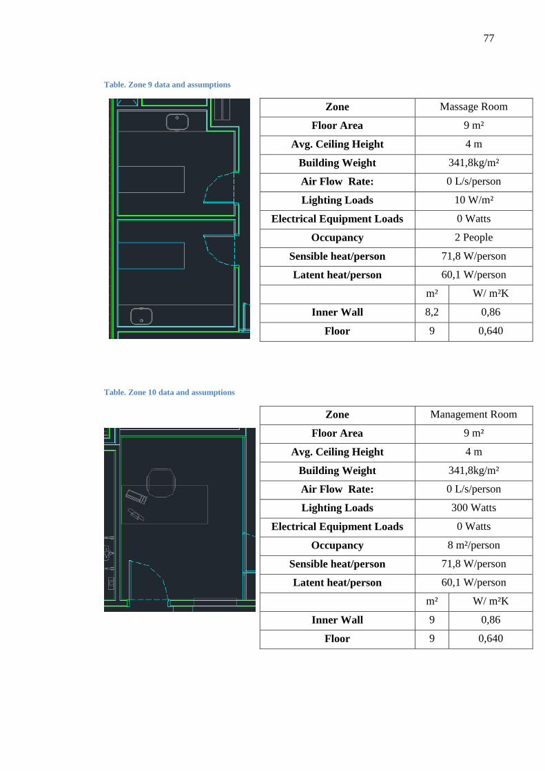
77
Table. Zone 9 data and assumptions
Zone Massage Room
Floor Area 9 m²
Avg. Ceiling Height 4 m
Building Weight 341,8kg/m²
Air Flow Rate: 0 L/s/person
Lighting Loads 10 W/m²
Electrical Equipment Loads 0 Watts
Occupancy 2 People
Sensible heat/person 71,8 W/person
Latent heat/person 60,1 W/person
m² W/ m²K
Inner Wall 8,2 0,86
Floor 9 0,640
Table. Zone 10 data and assumptions
Zone Management Room
Floor Area 9 m²
Avg. Ceiling Height 4 m
Building Weight 341,8kg/m²
Air Flow Rate: 0 L/s/person
Lighting Loads 300 Watts
Electrical Equipment Loads 0 Watts
Occupancy 8 m²/person
Sensible heat/person 71,8 W/person
Latent heat/person 60,1 W/person
m² W/ m²K
Inner Wall 9 0,86
Floor 9 0,640
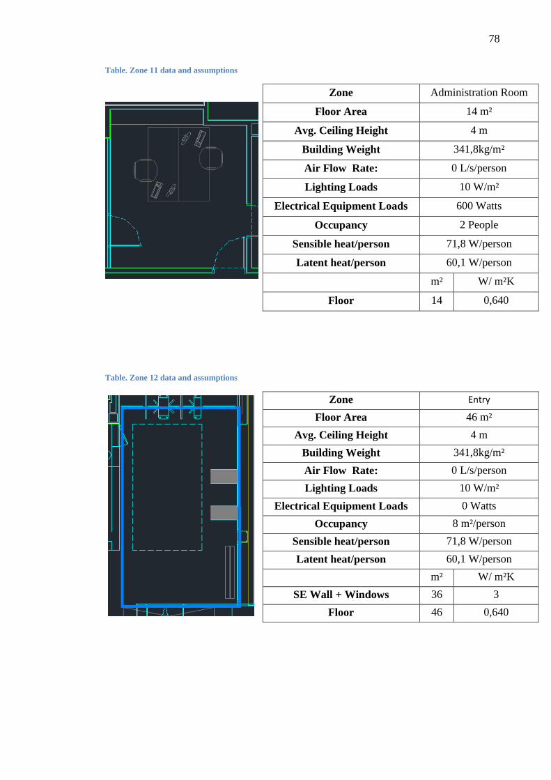
78
Table. Zone 11 data and assumptions
Zone Administration Room
Floor Area 14 m²
Avg. Ceiling Height 4 m
Building Weight 341,8kg/m²
Air Flow Rate: 0 L/s/person
Lighting Loads 10 W/m²
Electrical Equipment Loads 600 Watts
Occupancy 2 People
Sensible heat/person 71,8 W/person
Latent heat/person 60,1 W/person
m² W/ m²K
Floor 14 0,640
Table. Zone 12 data and assumptions
Zone Entry
Floor Area 46 m²
Avg. Ceiling Height 4 m
Building Weight 341,8kg/m²
Air Flow Rate: 0 L/s/person
Lighting Loads 10 W/m²
Electrical Equipment Loads 0 Watts
Occupancy 8 m²/person
Sensible heat/person 71,8 W/person
Latent heat/person 60,1 W/person
m² W/ m²K
SE Wall + Windows 36 3
Floor 46 0,640
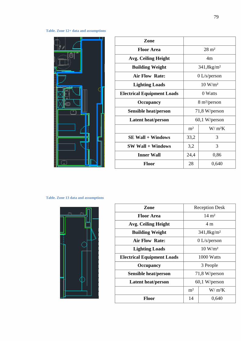
79
Table. Zone 12+ data and assumptions
Zone
Floor Area 28 m²
Avg. Ceiling Height 4m
Building Weight 341,8kg/m²
Air Flow Rate: 0 L/s/person
Lighting Loads 10 W/m²
Electrical Equipment Loads 0 Watts
Occupancy 8 m²/person
Sensible heat/person 71,8 W/person
Latent heat/person 60,1 W/person
m² W/ m²K
SE Wall + Windows 33,2 3
SW Wall + Windows 3,2 3
Inner Wall 24,4 0,86
Floor 28 0,640
Table. Zone 13 data and assumptions
Zone Reception Desk
Floor Area 14 m²
Avg. Ceiling Height 4 m
Building Weight 341,8kg/m²
Air Flow Rate: 0 L/s/person
Lighting Loads 10 W/m²
Electrical Equipment Loads 1000 Watts
Occupancy 3 People
Sensible heat/person 71,8 W/person
Latent heat/person 60,1 W/person
m² W/ m²K
Floor 14 0,640

80
Table. Zone 14 data and assumptions
Zone Entry
Floor Area 11 m²
Avg. Ceiling Height 4 m
Building Weight 341,8kg/m²
Air Flow Rate: 8 L/s/person
Lighting Loads 10 W/m²
Electrical Equipment Loads 0 Watts
Occupancy 30 People
Sensible heat/person 71,8 W/person
Latent heat/person 60,1 W/person
m² W/ m²K
SE Wall + Windows 7 3
SW Wall + Windows 16 3
NE Wall + Windows 2 3
Floor 11 0,640
Table. Zone 15 data and assumptions
Zone Swimming Instr.Room
Floor Area 13 m²
Avg. Ceiling Height 4 m
Building Weight 341,8kg/m²
Air Flow Rate: 0 L/s/person
Lighting Loads 10 W/m²
Electrical Equipment Loads 0 Watts
Occupancy 8 m²/person
Sensible heat/person 71,8 W/person
Latent heat/person 60,1 W/person
m² W/ m²K
Floor 13 0,640
Inner Wall 38 0,86

81
Table. Zone 16 data and assumptions
Zone
Floor Area 67 m²
Avg. Ceiling Height 4 m
Building Weight 341,8kg/m²
Air Flow Rate: 0 L/s/person
Lighting Loads 10 W/m²
Electrical Equipment Loads 0 Watts
Occupancy 8 m²/person
Sensible heat/person 71,8 W/person
Latent heat/person 60,1 W/person
m² W/ m²K
SE Wall + Windows 27 3
Inner Wall 73,2 0,86
Floor 67 0,640
Table. Zone 17 data and assumptions
Zone
Floor Area 17 m²
Avg. Ceiling Height 4 m
Building Weight 341,8kg/m²
Air Flow Rate: 0 L/s/person
Lighting Loads 10 W/m²
Electrical Equipment Loads 15 W/m²
Occupancy 3 m²/person
Sensible heat/person 71,8 W/person
Latent heat/person 60,1 W/person
m² W/ m²K
SE Wall 19 3
SW Wall + Windows 16 3
NE Wall + Windows 2 3
Floor 17 0,640

82
Table. Zone 18 data and assumptions
Zone Locker Room
Floor Area 127 m²
Avg. Ceiling Height 4 m
Building Weight 341,8kg/m²
Air Flow Rate: 8 L/s/person
Lighting Loads 2160 W
Electrical Equipment Loads 6000 Watts
Occupancy 60 People
Sensible heat/person 71,8 W/person
Latent heat/person 60,1 W/person
m² W/ m²K
NW Wall 22,5 3
NE Wall 70 3
SE Wall 22,5 3
Inner Wall 108 0,86
Floor 127 0,640
Table. Zone 20 data and assumptions
Zone Locker Room
Floor Area 78 m²
Avg. Ceiling Height 4 m
Building Weight 341,8kg/m²
Air Flow Rate: 8 L/s/person
Lighting Loads 1500 W
Electrical Equipment Loads 6000 W
Occupancy 20 People
Sensible heat/person 71,8 W/person
Latent heat/person 60,1 W/person
m² W/ m²K
Inner Wall 2 0,86
Floor 78 0,640

83
Table. Zone 21 data and assumptions
Zone Locker Room
Floor Area 120 m²
Avg. Ceiling Height 4 m
Building Weight 341,8kg/m²
Air Flow Rate: 8 L/s/person
Lighting Loads 2160 W
Electrical Equipment Loads 6000 W
Occupancy 60 People
Sensible heat/person 71,8 W/person
Latent heat/person 60,1 W/person
m² W/ m²K
Inner Wall 96 0,86
Floor 120 0,640
84
APPENDIX D. DIFFUSION STUDY CHARTS
Figure 1. Pressure drop and sound power level
Figure 2. Velocity of the air jet for the throw

85
Figure 3. Vertical deviation of the air jet (non-isothermal jets)
Figure 4. Ratio between air flow velocities.

86
Figure 5. Induction rate
Figure 6. Ratio between temperature differences