Thermal Stability of Retained Austenite in Bainitic …Thermal Stability of Retained Austenite in...
19
Thermal Stability of Retained Austenite in Bainitic Steel: an in situ study By A. Saha Podder, I. Lonardelli, A. Molinari and H. K. D. H. Bhadeshia University of Cambridge Materials Science and Metallurgy Pembroke Street, Cambridge CB2 3QZ, U. K. University of Trento Materials Engineering and Industrial Technologies Via Mesiano 77, 38123 Trento, Italy Abstract The tempering of two–phase mixtures of bainitic ferrite and carbon–enriched re- tained austenite has been investigated in an effort to separate the reactions that occur at elevated temperatures from any transformation during cooling to ambient conditions. It is demonstrated using synchrotron X–radiation measurements, that the residue of austenite left at the tempering temperature partly decomposes by martensitic transformation when the sample is cooled. It is well–established in the published literature that films of retained austenite are better able to resist stress or strain–induced martensitic transformation than any coarser particles of austen- ite. In contrast, the coarser austenite is more thermally stable than the film form because of its lower carbon concentration. 1. Introduction Carbide–free bainitic steels in which a proportion of the microstructure consists of a mixture of bainitic ferrite and carbon–enriched retained austenite are now well– established as some of the most sophisticated engineering materials. Applications range from the formable alloys for the automobile industry (Matsumura et al., 1987a,b), ductile cast–irons (Rundman and Klug, 1982), railway lines (Bhadeshia, 2007; Yates, 1996) and armour (Bhadeshia, 2005; Caballero and Bhadeshia, 2004). There also exist many variants of the basic concept which are the subject of intense research from both a fundamental and applied perspective (Caballero et al., 2010; Menapace et al., 2009; Saha Podder et al., 2007; Stone et al., 2008; Sugimoto, 2009; Yi et al., 2010). Structures of this kind, but on a scale finer than carbon nanotubes, can now be produced on a commercial scale, as reviewed recently (Bhadeshia, 2010). T E X Paper
Transcript of Thermal Stability of Retained Austenite in Bainitic …Thermal Stability of Retained Austenite in...
Thermal Stability of Retained Austenite
in Bainitic Steel: an in situ study
By A. Saha Podder, I. Lonardelli, A. Molinari and H. K. D. H.Bhadeshia
University of CambridgeMaterials Science and Metallurgy
Pembroke Street, Cambridge CB2 3QZ, U. K.
University of TrentoMaterials Engineering and Industrial Technologies
Via Mesiano 77, 38123 Trento, Italy
Abstract
The tempering of two–phase mixtures of bainitic ferrite and carbon–enriched re-tained austenite has been investigated in an e!ort to separate the reactions thatoccur at elevated temperatures from any transformation during cooling to ambientconditions. It is demonstrated using synchrotron X–radiation measurements, thatthe residue of austenite left at the tempering temperature partly decomposes bymartensitic transformation when the sample is cooled. It is well–established in thepublished literature that films of retained austenite are better able to resist stressor strain–induced martensitic transformation than any coarser particles of austen-ite. In contrast, the coarser austenite is more thermally stable than the film formbecause of its lower carbon concentration.
1. Introduction
Carbide–free bainitic steels in which a proportion of the microstructure consists ofa mixture of bainitic ferrite and carbon–enriched retained austenite are now well–established as some of the most sophisticated engineering materials. Applicationsrange from the formable alloys for the automobile industry (Matsumura et al.,1987a,b), ductile cast–irons (Rundman and Klug, 1982), railway lines (Bhadeshia,2007; Yates, 1996) and armour (Bhadeshia, 2005; Caballero and Bhadeshia, 2004).There also exist many variants of the basic concept which are the subject of intenseresearch from both a fundamental and applied perspective (Caballero et al., 2010;Menapace et al., 2009; Saha Podder et al., 2007; Stone et al., 2008; Sugimoto, 2009;Yi et al., 2010). Structures of this kind, but on a scale finer than carbon nanotubes,can now be produced on a commercial scale, as reviewed recently (Bhadeshia, 2010).
TEX Paper
Harshad Bhadeshia
Proceedings of the Royal Society A 467 (2011) 3141-3156doi: 10.1098/rspa.2011.0212
2 A. Saha Podder, I. Lonardelli, A. Molinari and H. K. D. H. Bhadeshia
One role of retained austenite is to enhance the ductility of the steel (DeCooman,2004; Jacques, 2004). It transforms under the influence of stress and strain andthereby increases the work–hardening rate su"ciently to delay plastic instabili-ties; the transformation strain itself plays a minor role in this process (Bhadeshia,2002). The mechanical stability of the austenite is well understood and serves as amechanism for controlling the properties.
However, there are circumstances in which the steel, after it is produced withthe desired microstructure, is subjected temporarily to an elevated temperature inexcess of 400!C; one example is the galvanising treatment where the steel passesthrough a bath of a molten zinc–rich alloy. Another case is where aeroengine shafts,which do not experience high temperatures during service, have to be heated totemperatures in excess of 500!C in order to apply corrosion–resistant coatings. It ispossible that the thermal stability of the austenite would not in these cases be suf-ficient, leading to its decomposition into a thermodynamically more stable mixtureof ferrite and cementite. Bearing this in mind, Saha Podder and Bhadeshia (2010)investigated the kinetics of the decomposition of carbon–enriched retained austen-ite as a function of a tempering heat treatment, using a combination of microscopyand X–ray di!raction on samples cooled to ambient temperature following the ex-cursion to elevated temperatures. When the mixture of bainitic ferrite and retainedaustenite (!r) is heated to the tempering temperature, some of the austenite un-dergoes thermal decomposition into a mixture of bainitic ferrite ("b) and cementite(#) but a proportion of the remainder may decompose into martensite ("") duringcooling to ambient temperature. It follows that the quantities measured are a com-bination of two decomposition reactions rather than just the influence of thermaldecomposition:
!r
temper
!!!!!" !r + # + "b
cool
!!!!!" !r + # + "b + ""
where the amount of austenite is reduced at each stage of the process.
The purpose of this work was to characterise separately the two reactions ofthermal decomposition and the transformation to martensite during cooling fromthe tempering temperature, by using high–energy synchrotron X–rays to conduct insitu experiments. The work is a part of basic research in which we hope to increasethe thermal stability of bulk nanostructured steels (Bhadeshia, 2010).
2. Experimental Procedure
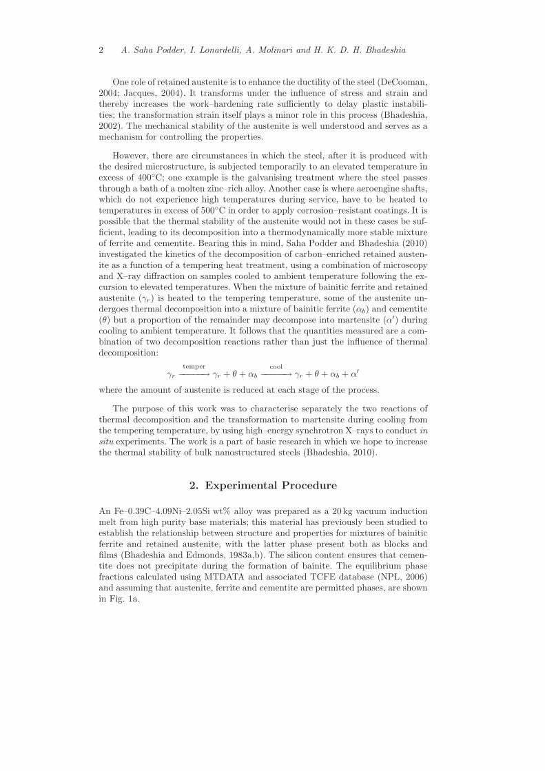
An Fe–0.39C–4.09Ni–2.05Si wt% alloy was prepared as a 20 kg vacuum inductionmelt from high purity base materials; this material has previously been studied toestablish the relationship between structure and properties for mixtures of bainiticferrite and retained austenite, with the latter phase present both as blocks andfilms (Bhadeshia and Edmonds, 1983a,b). The silicon content ensures that cemen-tite does not precipitate during the formation of bainite. The equilibrium phasefractions calculated using MTDATA and associated TCFE database (NPL, 2006)and assuming that austenite, ferrite and cementite are permitted phases, are shownin Fig. 1a.
Thermal Stability of Retained Austenite in Bainitic Steel: an in situ study 3
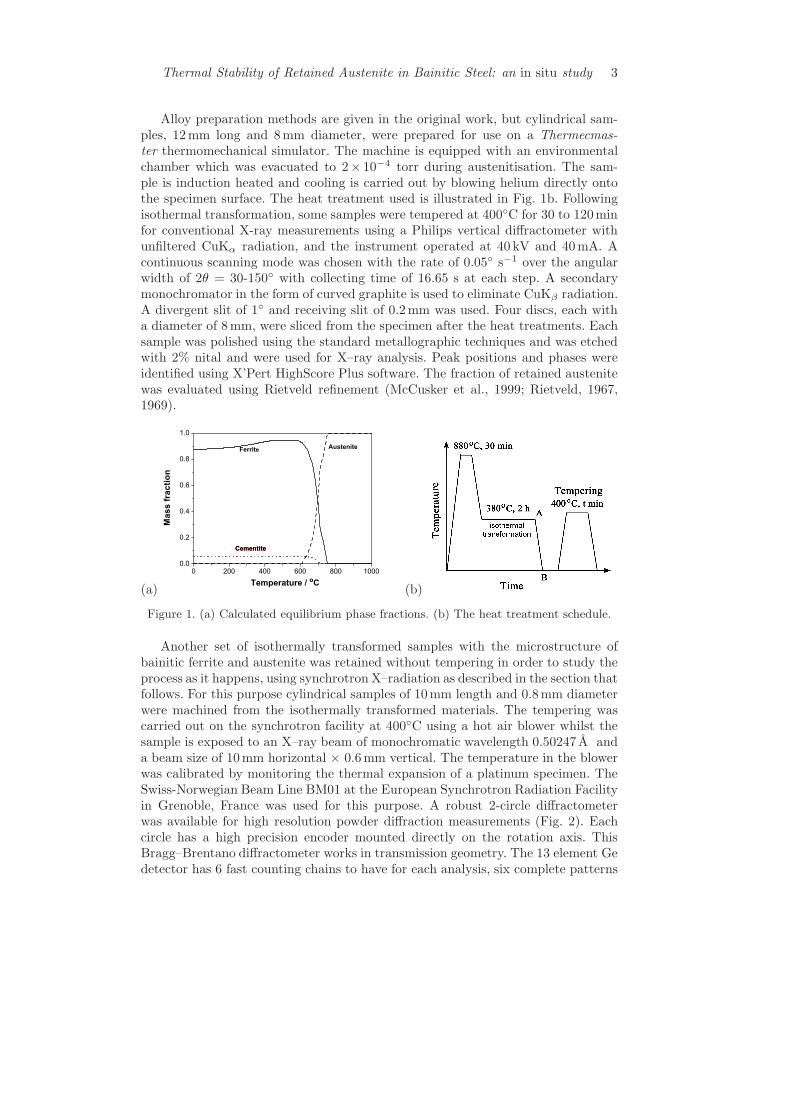
Alloy preparation methods are given in the original work, but cylindrical sam-ples, 12mm long and 8mm diameter, were prepared for use on a Thermecmas-ter thermomechanical simulator. The machine is equipped with an environmentalchamber which was evacuated to 2# 10#4 torr during austenitisation. The sam-ple is induction heated and cooling is carried out by blowing helium directly ontothe specimen surface. The heat treatment used is illustrated in Fig. 1b. Followingisothermal transformation, some samples were tempered at 400!C for 30 to 120minfor conventional X-ray measurements using a Philips vertical di!ractometer withunfiltered CuK! radiation, and the instrument operated at 40 kV and 40mA. Acontinuous scanning mode was chosen with the rate of 0.05! s#1 over the angularwidth of 2# = 30-150! with collecting time of 16.65 s at each step. A secondarymonochromator in the form of curved graphite is used to eliminate CuK" radiation.A divergent slit of 1! and receiving slit of 0.2mm was used. Four discs, each witha diameter of 8mm, were sliced from the specimen after the heat treatments. Eachsample was polished using the standard metallographic techniques and was etchedwith 2% nital and were used for X–ray analysis. Peak positions and phases wereidentified using X’Pert HighScore Plus software. The fraction of retained austenitewas evaluated using Rietveld refinement (McCusker et al., 1999; Rietveld, 1967,1969).
(a) (b)
Figure 1. (a) Calculated equilibrium phase fractions. (b) The heat treatment schedule.
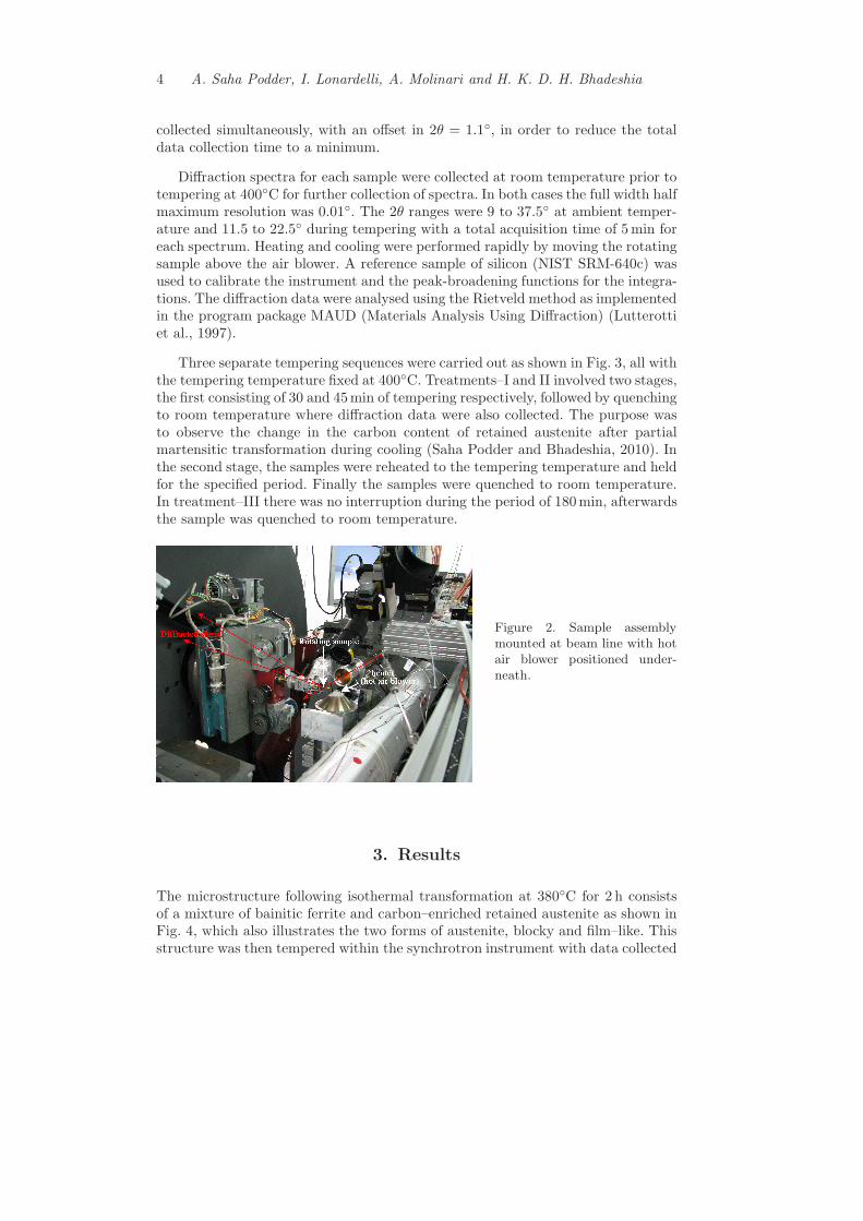
Another set of isothermally transformed samples with the microstructure ofbainitic ferrite and austenite was retained without tempering in order to study theprocess as it happens, using synchrotron X–radiation as described in the section thatfollows. For this purpose cylindrical samples of 10mm length and 0.8mm diameterwere machined from the isothermally transformed materials. The tempering wascarried out on the synchrotron facility at 400!C using a hot air blower whilst thesample is exposed to an X–ray beam of monochromatic wavelength 0.50247 A anda beam size of 10mm horizontal # 0.6mm vertical. The temperature in the blowerwas calibrated by monitoring the thermal expansion of a platinum specimen. TheSwiss-Norwegian Beam Line BM01 at the European Synchrotron Radiation Facilityin Grenoble, France was used for this purpose. A robust 2-circle di!ractometerwas available for high resolution powder di!raction measurements (Fig. 2). Eachcircle has a high precision encoder mounted directly on the rotation axis. ThisBragg–Brentano di!ractometer works in transmission geometry. The 13 element Gedetector has 6 fast counting chains to have for each analysis, six complete patterns
4 A. Saha Podder, I. Lonardelli, A. Molinari and H. K. D. H. Bhadeshia
collected simultaneously, with an o!set in 2# = 1.1!, in order to reduce the totaldata collection time to a minimum.
Di!raction spectra for each sample were collected at room temperature prior totempering at 400!C for further collection of spectra. In both cases the full width halfmaximum resolution was 0.01!. The 2# ranges were 9 to 37.5! at ambient temper-ature and 11.5 to 22.5! during tempering with a total acquisition time of 5 min foreach spectrum. Heating and cooling were performed rapidly by moving the rotatingsample above the air blower. A reference sample of silicon (NIST SRM-640c) wasused to calibrate the instrument and the peak-broadening functions for the integra-tions. The di!raction data were analysed using the Rietveld method as implementedin the program package MAUD (Materials Analysis Using Di!raction) (Lutterottiet al., 1997).
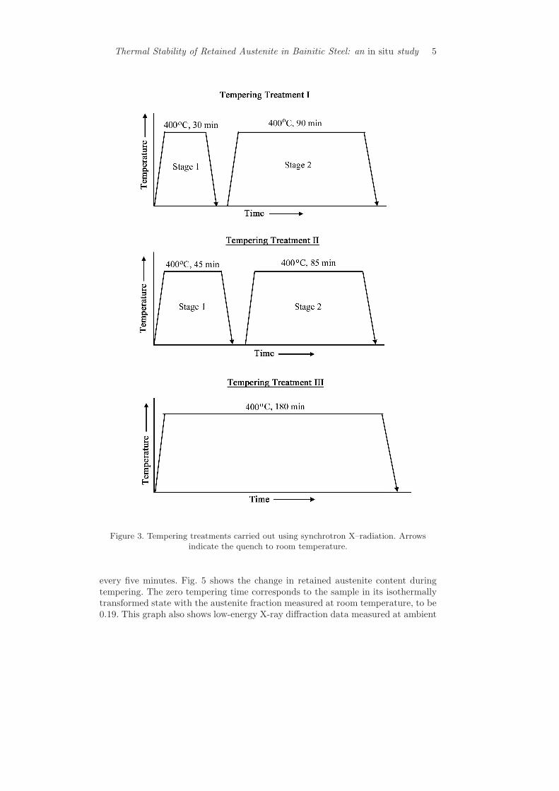
Three separate tempering sequences were carried out as shown in Fig. 3, all withthe tempering temperature fixed at 400!C. Treatments–I and II involved two stages,the first consisting of 30 and 45min of tempering respectively, followed by quenchingto room temperature where di!raction data were also collected. The purpose wasto observe the change in the carbon content of retained austenite after partialmartensitic transformation during cooling (Saha Podder and Bhadeshia, 2010). Inthe second stage, the samples were reheated to the tempering temperature and heldfor the specified period. Finally the samples were quenched to room temperature.In treatment–III there was no interruption during the period of 180min, afterwardsthe sample was quenched to room temperature.
Figure 2. Sample assemblymounted at beam line with hotair blower positioned under-neath.
3. Results
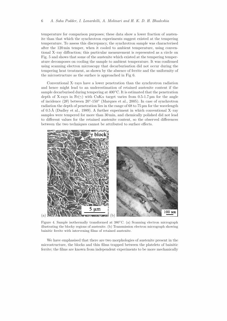
The microstructure following isothermal transformation at 380!C for 2 h consistsof a mixture of bainitic ferrite and carbon–enriched retained austenite as shown inFig. 4, which also illustrates the two forms of austenite, blocky and film–like. Thisstructure was then tempered within the synchrotron instrument with data collected
Thermal Stability of Retained Austenite in Bainitic Steel: an in situ study 5
Figure 3. Tempering treatments carried out using synchrotron X–radiation. Arrowsindicate the quench to room temperature.
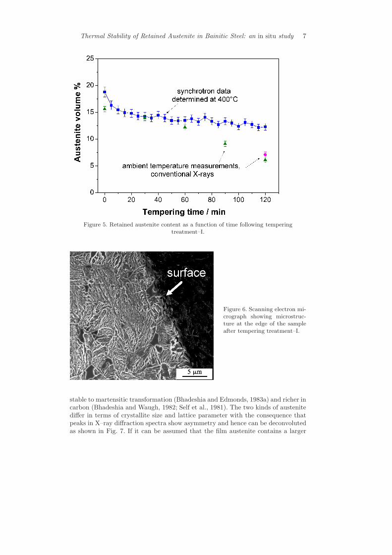
every five minutes. Fig. 5 shows the change in retained austenite content duringtempering. The zero tempering time corresponds to the sample in its isothermallytransformed state with the austenite fraction measured at room temperature, to be0.19. This graph also shows low-energy X-ray di!raction data measured at ambient
6 A. Saha Podder, I. Lonardelli, A. Molinari and H. K. D. H. Bhadeshia
temperature for comparison purposes; these data show a lower fraction of austen-ite than that which the synchrotron experiments suggest existed at the temperingtemperature. To assess this discrepancy, the synchrotron sample was characterisedafter the 120min temper, when it cooled to ambient temperature, using conven-tional X–ray di!raction; this particular measurement is represented as a circle onFig. 5 and shows that some of the austenite which existed at the tempering temper-ature decomposes on cooling the sample to ambient temperature. It was confirmedusing scanning electron microscopy that decarburisation did not occur during thetempering heat treatment, as shown by the absence of ferrite and the uniformity ofthe microstructure as the surface is approached in Fig 6.
Conventional X–rays have a lower penetration than the synchrotron radiationand hence might lead to an underestimation of retained austenite content if thesample decarburised during tempering at 400!C. It is estimated that the penetrationdepth of X-rays in Fe(!) with CuK" target varies from 0.5-1.7µm for the angleof incidence (2#) between 20!-150! (Marques et al., 2005). In case of synchrotronradiation the depth of penetration lies in the range of 68 to 75µm for the wavelengthof 0.5 A (Dudley et al., 1989). A further experiment in which conventional X–raysamples were tempered for more than 30min, and chemically polished did not leadto di!erent values for the retained austenite content, so the observed di!erencesbetween the two techniques cannot be attributed to surface e!ects.
(a) (b)
Figure 4. Sample isothermally transformed at 380!C. (a) Scanning electron micrographillustrating the blocky regions of austenite. (b) Transmission electron micrograph showingbainitic ferrite with intervening films of retained austenite.
We have emphasised that there are two morphologies of austenite present in themicrostructure, the blocks and thin films trapped between the platelets of bainiticferrite; the films are known from independent experiments to be more mechanically
Thermal Stability of Retained Austenite in Bainitic Steel: an in situ study 7
Figure 5. Retained austenite content as a function of time following temperingtreatment–I.
Figure 6. Scanning electron mi-crograph showing microstruc-ture at the edge of the sampleafter tempering treatment–I.
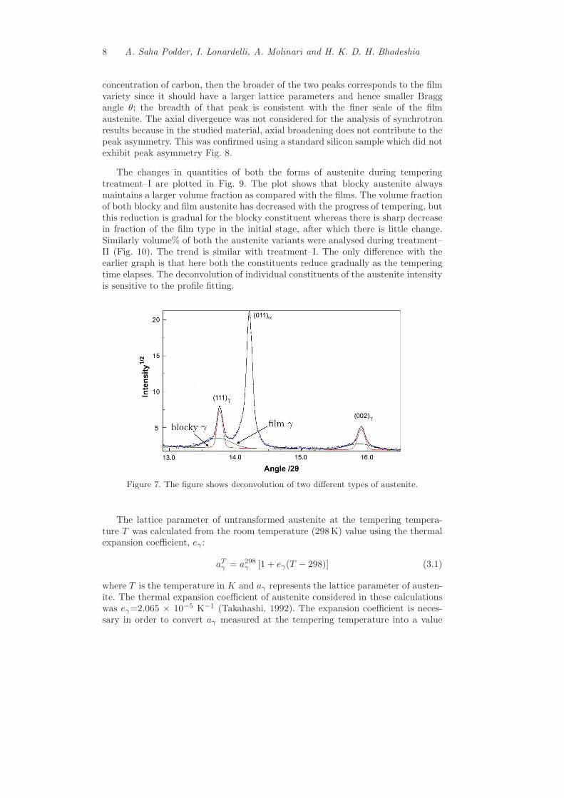
stable to martensitic transformation (Bhadeshia and Edmonds, 1983a) and richer incarbon (Bhadeshia and Waugh, 1982; Self et al., 1981). The two kinds of austenitedi!er in terms of crystallite size and lattice parameter with the consequence thatpeaks in X–ray di!raction spectra show asymmetry and hence can be deconvolutedas shown in Fig. 7. If it can be assumed that the film austenite contains a larger
8 A. Saha Podder, I. Lonardelli, A. Molinari and H. K. D. H. Bhadeshia
concentration of carbon, then the broader of the two peaks corresponds to the filmvariety since it should have a larger lattice parameters and hence smaller Braggangle #; the breadth of that peak is consistent with the finer scale of the filmaustenite. The axial divergence was not considered for the analysis of synchrotronresults because in the studied material, axial broadening does not contribute to thepeak asymmetry. This was confirmed using a standard silicon sample which did notexhibit peak asymmetry Fig. 8.
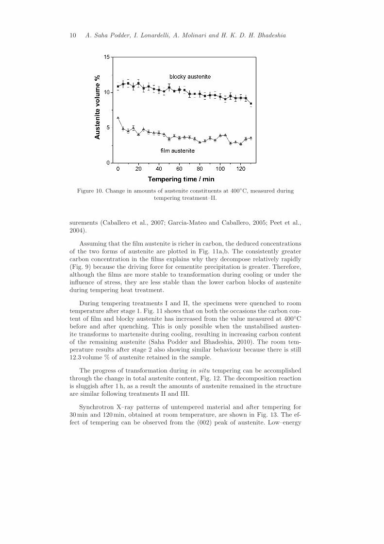
The changes in quantities of both the forms of austenite during temperingtreatment–I are plotted in Fig. 9. The plot shows that blocky austenite alwaysmaintains a larger volume fraction as compared with the films. The volume fractionof both blocky and film austenite has decreased with the progress of tempering, butthis reduction is gradual for the blocky constituent whereas there is sharp decreasein fraction of the film type in the initial stage, after which there is little change.Similarly volume% of both the austenite variants were analysed during treatment–II (Fig. 10). The trend is similar with treatment–I. The only di!erence with theearlier graph is that here both the constituents reduce gradually as the temperingtime elapses. The deconvolution of individual constituents of the austenite intensityis sensitive to the profile fitting.
Figure 7. The figure shows deconvolution of two di!erent types of austenite.
The lattice parameter of untransformed austenite at the tempering tempera-ture T was calculated from the room temperature (298K) value using the thermalexpansion coe"cient, e# :
aT# = a298
# [1 + e#(T ! 298)] (3.1)
where T is the temperature in K and a# represents the lattice parameter of austen-ite. The thermal expansion coe"cient of austenite considered in these calculationswas e#=2.065 # 10#5 K#1 (Takahashi, 1992). The expansion coe"cient is neces-sary in order to convert a# measured at the tempering temperature into a value

Thermal Stability of Retained Austenite in Bainitic Steel: an in situ study 9
Figure 8. Superimposed peaks from the standard silicon sample.
Figure 9. Change in amounts of blocky and film–type austenite at 400!C duringtempering treatment–I.
at ambient temperature, in order to permit the composition of the austenite to beestimated. The carbon content of retained austenite was calculated using the rela-tionship between lattice parameter and chemical composition reported by (Dysonand Holmes, 1970). This expression was selected as being the most complete interms of the contribution of di!erent solutes to the austenite lattice parameterand its use has been validated due to reasonable agreement with atom probe mea-
10 A. Saha Podder, I. Lonardelli, A. Molinari and H. K. D. H. Bhadeshia
Figure 10. Change in amounts of austenite constituents at 400!C, measured duringtempering treatment–II.
surements (Caballero et al., 2007; Garcia-Mateo and Caballero, 2005; Peet et al.,2004).
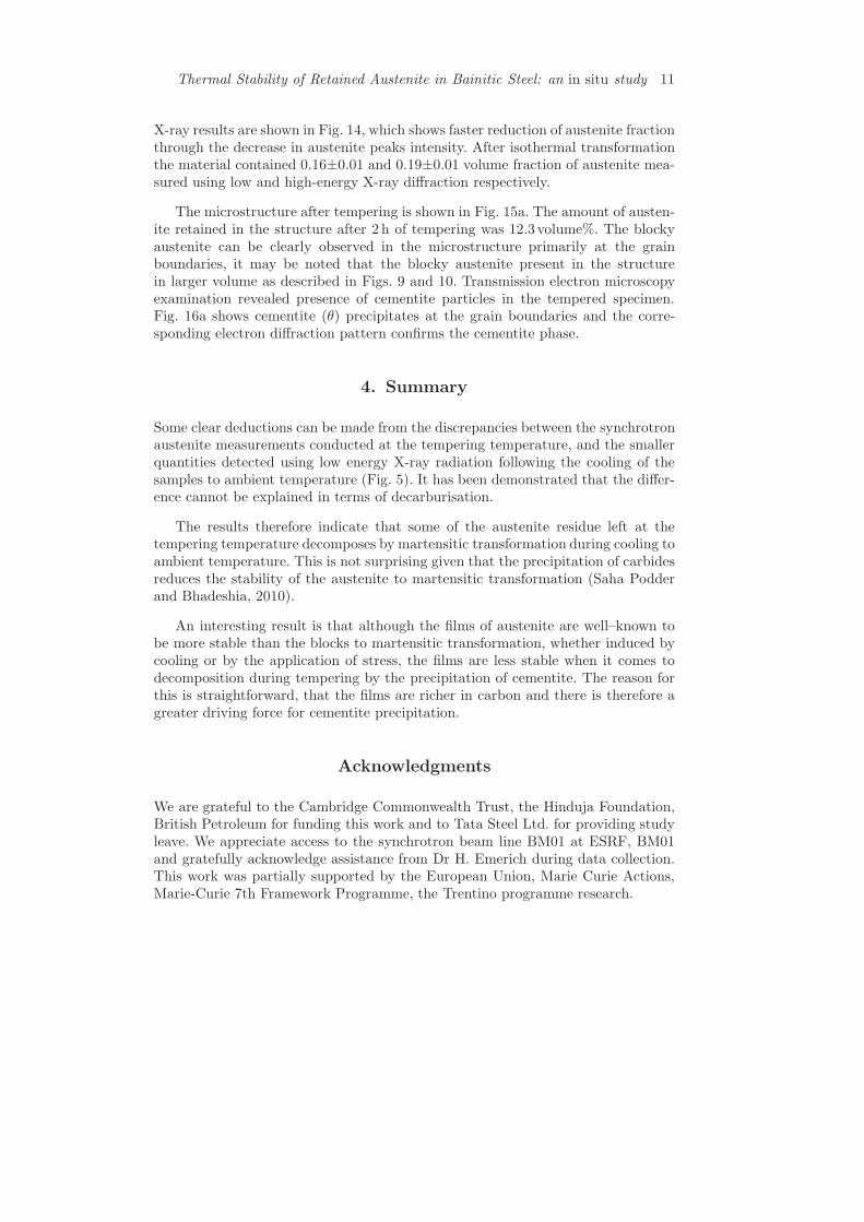
Assuming that the film austenite is richer in carbon, the deduced concentrationsof the two forms of austenite are plotted in Fig. 11a,b. The consistently greatercarbon concentration in the films explains why they decompose relatively rapidly(Fig. 9) because the driving force for cementite precipitation is greater. Therefore,although the films are more stable to transformation during cooling or under theinfluence of stress, they are less stable than the lower carbon blocks of austeniteduring tempering heat treatment.
During tempering treatments I and II, the specimens were quenched to roomtemperature after stage 1. Fig. 11 shows that on both the occasions the carbon con-tent of film and blocky austenite has increased from the value measured at 400!Cbefore and after quenching. This is only possible when the unstabilised austen-ite transforms to martensite during cooling, resulting in increasing carbon contentof the remaining austenite (Saha Podder and Bhadeshia, 2010). The room tem-perature results after stage 2 also showing similar behaviour because there is still12.3 volume % of austenite retained in the sample.
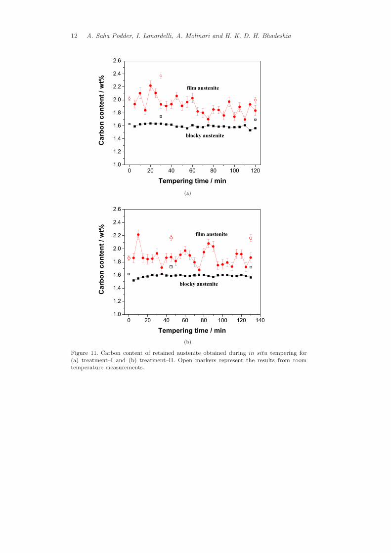
The progress of transformation during in situ tempering can be accomplishedthrough the change in total austenite content, Fig. 12. The decomposition reactionis sluggish after 1 h, as a result the amounts of austenite remained in the structureare similar following treatments II and III.
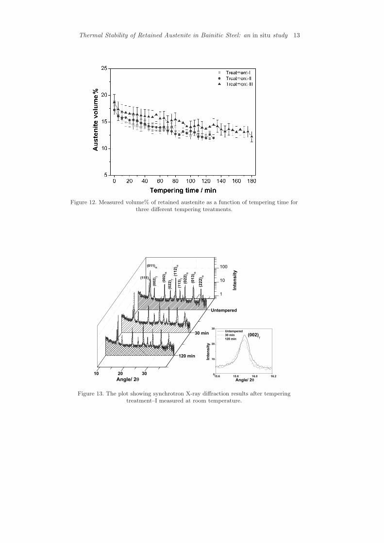
Synchrotron X–ray patterns of untempered material and after tempering for30min and 120min, obtained at room temperature, are shown in Fig. 13. The ef-fect of tempering can be observed from the (002) peak of austenite. Low–energy
Thermal Stability of Retained Austenite in Bainitic Steel: an in situ study 11
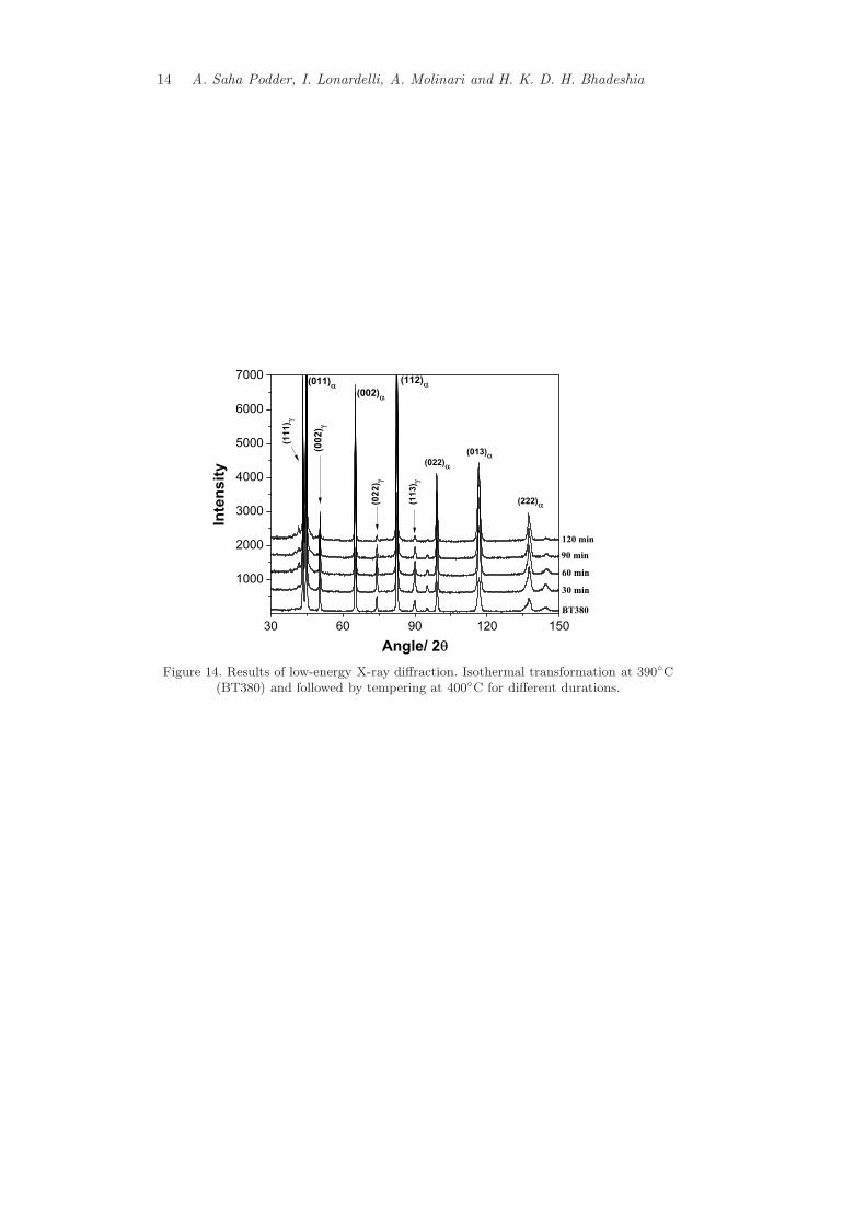
X-ray results are shown in Fig. 14, which shows faster reduction of austenite fractionthrough the decrease in austenite peaks intensity. After isothermal transformationthe material contained 0.16±0.01 and 0.19±0.01 volume fraction of austenite mea-sured using low and high-energy X-ray di!raction respectively.
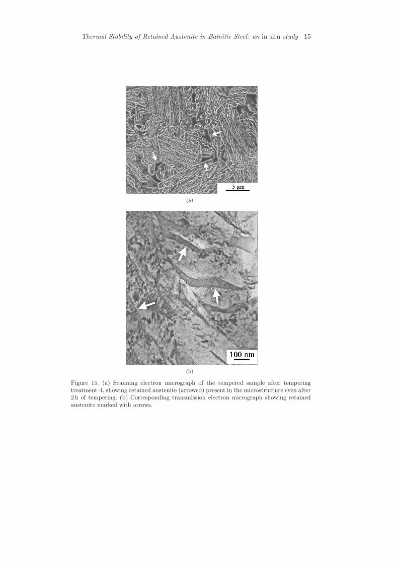
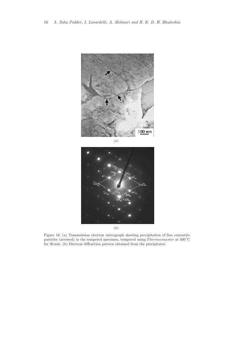
The microstructure after tempering is shown in Fig. 15a. The amount of austen-ite retained in the structure after 2 h of tempering was 12.3 volume%. The blockyaustenite can be clearly observed in the microstructure primarily at the grainboundaries, it may be noted that the blocky austenite present in the structurein larger volume as described in Figs. 9 and 10. Transmission electron microscopyexamination revealed presence of cementite particles in the tempered specimen.Fig. 16a shows cementite (#) precipitates at the grain boundaries and the corre-sponding electron di!raction pattern confirms the cementite phase.
4. Summary
Some clear deductions can be made from the discrepancies between the synchrotronaustenite measurements conducted at the tempering temperature, and the smallerquantities detected using low energy X-ray radiation following the cooling of thesamples to ambient temperature (Fig. 5). It has been demonstrated that the di!er-ence cannot be explained in terms of decarburisation.
The results therefore indicate that some of the austenite residue left at thetempering temperature decomposes by martensitic transformation during cooling toambient temperature. This is not surprising given that the precipitation of carbidesreduces the stability of the austenite to martensitic transformation (Saha Podderand Bhadeshia, 2010).
An interesting result is that although the films of austenite are well–known tobe more stable than the blocks to martensitic transformation, whether induced bycooling or by the application of stress, the films are less stable when it comes todecomposition during tempering by the precipitation of cementite. The reason forthis is straightforward, that the films are richer in carbon and there is therefore agreater driving force for cementite precipitation.
Acknowledgments
We are grateful to the Cambridge Commonwealth Trust, the Hinduja Foundation,British Petroleum for funding this work and to Tata Steel Ltd. for providing studyleave. We appreciate access to the synchrotron beam line BM01 at ESRF, BM01and gratefully acknowledge assistance from Dr H. Emerich during data collection.This work was partially supported by the European Union, Marie Curie Actions,Marie-Curie 7th Framework Programme, the Trentino programme research.
12 A. Saha Podder, I. Lonardelli, A. Molinari and H. K. D. H. Bhadeshia
(a)
(b)
Figure 11. Carbon content of retained austenite obtained during in situ tempering for(a) treatment–I and (b) treatment–II. Open markers represent the results from roomtemperature measurements.
Thermal Stability of Retained Austenite in Bainitic Steel: an in situ study 13
Figure 12. Measured volume% of retained austenite as a function of tempering time forthree di!erent tempering treatments.
Figure 13. The plot showing synchrotron X-ray di!raction results after temperingtreatment–I measured at room temperature.
14 A. Saha Podder, I. Lonardelli, A. Molinari and H. K. D. H. Bhadeshia
Figure 14. Results of low-energy X-ray di!raction. Isothermal transformation at 390!C(BT380) and followed by tempering at 400!C for di!erent durations.
Thermal Stability of Retained Austenite in Bainitic Steel: an in situ study 15
(a)
(b)
Figure 15. (a) Scanning electron micrograph of the tempered sample after temperingtreatment–I, showing retained austenite (arrowed) present in the microstructure even after2 h of tempering. (b) Corresponding transmission electron micrograph showing retainedaustenite marked with arrows.
16 A. Saha Podder, I. Lonardelli, A. Molinari and H. K. D. H. Bhadeshia
(a)
(b)
Figure 16. (a) Transmission electron micrograph showing precipitation of fine cementiteparticles (arrowed) in the tempered specimen, tempered using Thermecmaster at 400!Cfor 30min. (b) Electron di!raction pattern obtained from the precipitates.
Thermal Stability of Retained Austenite in Bainitic Steel: an in situ study 17
References
Bhadeshia, H. K. D. H., 2002. TRIP–assisted steels? ISIJ International 42, 1059–1060.
Bhadeshia, H. K. D. H., 2005. Large chunks of very strong steel. Materials Scienceand Technology 21, 1293–1302.
Bhadeshia, H. K. D. H., 2007. Steels for rails. In: Encyclopedia of Materials Science.Pergamon Press, Oxford, Elsevier Science, pp. 1–7.
Bhadeshia, H. K. D. H., 2010. Nanostructured bainite. Proceedings of the RoyalSociety of London A 466, 3–18.
Bhadeshia, H. K. D. H., Edmonds, D. V., 1983a. Bainite in silicon steels: a newcomposition property approach i. Metal Science 17, 411–419.
Bhadeshia, H. K. D. H., Edmonds, D. V., 1983b. Bainite in silicon steels: a newcomposition property approach ii. Metal Science 17, 420–425.
Bhadeshia, H. K. D. H., Waugh, A. R., 1982. Bainite: An atom probe study of theincomplete reaction phenomenon. Acta Metallurgica 30, 775–784.
Caballero, F. G., Bhadeshia, H. K. D. H., 2004. Very strong bainite. Current Opin-ion in Solid State and Materials Science 8, 251–257.
Caballero, F. G., Miller, M. K., Babu, S. S., Garcia-Mateo, C., 2007. Atomic scaleobservations of bainite transformation in a high carbon high silicon steel. ActaMaterialia 55, 381–390.
Caballero, F. G., Miller, M. K., Garcia-Mateo, C., 2010. Tracking solute atoms dur-ing bainite reaction in a nanocrystalline steel. Materials Science and Technology26, 889–898.
DeCooman, B., 2004. Structure–properties relationship in TRIP steels containingcarbide-free bainite. Current Opinion in Solid State and Materials Science 8,285–303.
Dudley, M., Wu, J., Yao, G. D., 1989. Determination of penetration depths andanalysis of strains in single crystals by white beam synchrotron X-ray tomographyin grazing Bragg-Laue geometries. Nuclear Instruments and Methods in PhysicsResearch B40/41, 388–392.
Dyson, D. J., Holmes, B., 1970. E!ect of alloying additions on the lattice parameteraustenite. Journal of the Iron and Steel Institute 208, 469–474.
Garcia-Mateo, C., Caballero, F. G., 2005. Role of retained austenite on tensile prop-erties of steels with bainitic microstructures. Materials Transactions 46, 1839–1846.
Jacques, P. J., 2004. Transformation-induced plasticity for high strength formablesteels. Current Opinion in Solid State and Materials Science 8, 259–265.
18 A. Saha Podder, I. Lonardelli, A. Molinari and H. K. D. H. Bhadeshia
Lutterotti, L., Matthies, S., Wenk, H. R., Shultz, A. S., Richardson, J. W., 1997.Combined texture and structure analysis of deformed limestone from time-of-flight neutron di!raction spectra. Journal of Applied Physics 81, 594–600.
Marques, M. J., Pina, J., Dias, A. M., Lebrun, J. L., Feugeas, J., 2005. X-raydi!raction characterization of ion-implanted austenitic stainless steel. Surfaceand Coating Technology 195, 8–16.
Matsumura, O., Sakuma, Y., Takechi, H., 1987a. Enhancement of elongation byretained austenite in intercritical annealed 0.4C-1.5Si-0.8Mn steel. Transactionsof the Iron and Steel Institute of Japan 27, 570–579.
Matsumura, O., Sakuma, Y., Takechi, H., 1987b. TRIP and its kinetic aspects inaustempered 0.4C-1.5Si-0.8Mn steel. Scripta Metallurgica 27, 1301–1306.
McCusker, L. B., Dreele, R. B. V., Cox, D. E., Louer, D., Scardi, P., 1999. Rietveldrefinement guidelines. Journal of Applied Crystallography 32, 36–50.
Menapace, C., Lonardelli, I., Tait, M., Moinari, A., 2009. Nanostructured/ultrafinemultiphase steel with enhanced ductility obtained by mechanical alloying andspark plasma sintering of powders. Materials Science & Engineering A 517, 1–7.
NPL, 2006. MTDATA. Software, National Physical Laboratory, Teddington, U.K.
Peet, M., Garcia-Mateo, C., Caballero, F. G., Bhadeshia, H. K. D. H., 2004. Tem-pering of a hard mixture of bainitic ferrite and austenite. Materials Science andTechnology 20, 814–818.
Rietveld, H. M., 1967. Line profiles of neutron powder-di!raction peaks for structurerefinement. Acta Crystallographica 22, 151–152.
Rietveld, H. M., 1969. A profile refinement method for nuclear and magnetic struc-tures. Journal of Applied Crystallography 2, 65–71.
Rundman, K. B., Klug, R. C., 1982. X–ray and metallographic studies of an austem-pered ductile iron. Transactions of the American Foundrymen Society 90, 499–508.
Saha Podder, A., Bhadeshia, H. K. D. H., 2010. Thermal stability of austeniteretained in bainitic steels. Materials Science & Engineering A 527, 2121–2128.
Saha Podder, A., Bhattacharjee, D., Ray, R. K., 2007. E!ect of martensite on themechanical behavior of ferrite–bainite dual phase steels. ISIJ International 47,1058–1064.
Self, P. G., Bhadeshia, H. K. D. H., Stobbs, W. M., 1981. Lattice spacings fromlattice fringes. Ultramicroscopy 6, 29–40.
Stone, H. J., Peet, M. J., Bhadeshia, H. K. D. H., Withers, P. J., Babu, S. S.,Specht, E. D., 2008. Synchrotron X-ray studies of austenite and bainitic ferrite.Proceedings of the Royal Society A 464, 1009–1027.
Sugimoto, K. I., 2009. Fracture strength and toughness of ultra high strength TRIPaided steels. Materials Science and Technology 25, 1108–1117.
Thermal Stability of Retained Austenite in Bainitic Steel: an in situ study 19
Takahashi, M., 1992. Reaustenitisation from bainite in steels. Ph.D.thesis, University of Cambridge, http://www.msm.cam.ac.uk/phase-trans/2000/phd.html#Takahashi.
Yates, J. K., 1996. Innovation in rail steel. Science in Parliament 53, 2–3.
Yi, H. L., Lee, K. Y., Bhadeshia, H. K. D. H., 2010. Extraordinary ductility inAl–bearing $–TRIP steel. Proceedings of the Royal Society A 467, 234–243.
Harshad Bhadeshia
Proceedings of the Royal Society A 467 (2011) 3141-3156doi: 10.1098/rspa.2011.0212
Harshad Bhadeshia