Thermal performance of a solar cooker based on an evacuated tube solar collector with a PCM storage...
11
Thermal performance of a solar cooker based on an evacuated tube solar collector with a PCM storage unit S.D. Sharma a, * , Takeshi Iwata b , Hiroaki Kitano b , Kazunobu Sagara a,1 a Department of Architectural Engineering, Graduate School of Engineering, Osaka University, 2–1 Yamadaoka, Suita, Osaka 565-0871, Japan b Department of Architecture, Faculty of Engineering, Mie University, Tsu 514-8507, Japan Received 6 April 2004; received in revised form 20 July 2004; accepted 2 August 2004 Available online 11 September 2004 Communicated by: Associate Editor Michael Grupp Abstract The thermal performance of a prototype solar cooker based on an evacuated tube solar collector with phase change material (PCM) storage unit is investigated. The design has separate parts for energy collection and cooking coupled by a PCM storage unit. Solar energy is stored in the PCM storage unit during sunshine hours and is utilized for cooking in late evening/night time. Commercial grade erythritol was used as a latent heat storage material. Noon and evening cooking experiments were conducted with different loads and loading times. Cooking experiments and PCM storage processes were carried out simultaneously. It was observed that noon cooking did not affect the evening cooking, and evening cooking using PCM heat storage was found to be faster than noon cooking. The cooker performance under a variety of operating and climatic conditions was studied at Mie, Japan. Ó 2004 Elsevier Ltd. All rights reserved. Keywords: Solar energy; Phase change material; Latent heat storage; Evening cooking; Evacuated tube solar collector 1. Introduction Domanski et al. (1995) and Buddhi and Sahoo (1997) have studied the use of a phase change material (PCM) as a storage medium for a box type solar cooker de- signed to cook in the evening or during non-sunshine hours. They used stearic acid (melting point 69 °C) as a PCM for heat storage. Buddhi and Sahoo filled the PCM below the absorbing plate of the cooker. In such type of design, the rate of heat transfer from the PCM to the cooking pot during the discharging mode of the PCM is slow, and more time is required for cooking an evening meal. Sharma et al. (2000) designed and developed a cylin- drical PCM storage unit for a box type solar cooker to cook food in the late evening. Since this unit surrounds the cooking vessel, the rate of heat transfer between the PCM and the food is higher, and cooking can be faster. They reported that by using 2.0 kg of acetamide (melting point 82 °C) as a latent heat storage material, a second 0038-092X/$ - see front matter Ó 2004 Elsevier Ltd. All rights reserved. doi:10.1016/j.solener.2004.08.001 * Corresponding author. Tel.: +81 6 6879 7643; fax: +81 6 6879 7646. E-mail addresses: [email protected], sharma_ [email protected] (S.D. Sharma). 1 ISES member. Solar Energy 78 (2005) 416–426 www.elsevier.com/locate/solener
Transcript of Thermal performance of a solar cooker based on an evacuated tube solar collector with a PCM storage...

Solar Energy 78 (2005) 416–426
www.elsevier.com/locate/solener
Thermal performance of a solar cooker based on an evacuatedtube solar collector with a PCM storage unit
S.D. Sharma a,*, Takeshi Iwata b, Hiroaki Kitano b, Kazunobu Sagara a,1
a Department of Architectural Engineering, Graduate School of Engineering, Osaka University, 2–1 Yamadaoka, Suita,
Osaka 565-0871, Japanb Department of Architecture, Faculty of Engineering, Mie University, Tsu 514-8507, Japan
Received 6 April 2004; received in revised form 20 July 2004; accepted 2 August 2004
Available online 11 September 2004
Communicated by: Associate Editor Michael Grupp
Abstract
The thermal performance of a prototype solar cooker based on an evacuated tube solar collector with phase change
material (PCM) storage unit is investigated. The design has separate parts for energy collection and cooking coupled by
a PCM storage unit. Solar energy is stored in the PCM storage unit during sunshine hours and is utilized for cooking in
late evening/night time. Commercial grade erythritol was used as a latent heat storage material. Noon and evening
cooking experiments were conducted with different loads and loading times. Cooking experiments and PCM storage
processes were carried out simultaneously. It was observed that noon cooking did not affect the evening cooking,
and evening cooking using PCM heat storage was found to be faster than noon cooking. The cooker performance under
a variety of operating and climatic conditions was studied at Mie, Japan.
� 2004 Elsevier Ltd. All rights reserved.
Keywords: Solar energy; Phase change material; Latent heat storage; Evening cooking; Evacuated tube solar collector
1. Introduction
Domanski et al. (1995) and Buddhi and Sahoo (1997)
have studied the use of a phase change material (PCM)
as a storage medium for a box type solar cooker de-
signed to cook in the evening or during non-sunshine
hours. They used stearic acid (melting point 69 �C) as
0038-092X/$ - see front matter � 2004 Elsevier Ltd. All rights reserv
doi:10.1016/j.solener.2004.08.001
* Corresponding author. Tel.: +81 6 6879 7643; fax: +81 6
6879 7646.
E-mail addresses: [email protected], sharma_
[email protected] (S.D. Sharma).1 ISES member.
a PCM for heat storage. Buddhi and Sahoo filled the
PCM below the absorbing plate of the cooker. In such
type of design, the rate of heat transfer from the PCM
to the cooking pot during the discharging mode of the
PCM is slow, and more time is required for cooking
an evening meal.
Sharma et al. (2000) designed and developed a cylin-
drical PCM storage unit for a box type solar cooker to
cook food in the late evening. Since this unit surrounds
the cooking vessel, the rate of heat transfer between the
PCM and the food is higher, and cooking can be faster.
They reported that by using 2.0kg of acetamide (melting
point 82 �C) as a latent heat storage material, a second
ed.

Nomenclature
A net absorber area for the tubes (1.82m2 · 2 =
3.64m2)
Cw specific heat of water (=4.18kJ/kg �C)G solar irradiance (MJ)
Ii enthalpy of PCM (kJ/kg)
Ih (ave) average solar irradiance at horizontal sur-
face (W/m2)
Is20 solar irradiance at 20� angle inclined from
the horizontal surface (W/m2)
Is20(ave) average solar irradiance at 20� angle inclinedfrom the horizontal surface (W/m2)
m mass flow rate (lmin�1)
mave average mass flow rate (lmin�1)
Mi mass of PCM (kg)
Mload mass of loaded water (kg)
QPCMStored total heat stored in the PCM (kJ)
QwaterStored total heat gain by water (HTF) (kJ)
Ta ambient air temperature (�C)Ta(ave) average ambient air temperature (�C)Tin water (HTF) temperature at the inlet of the
ETSC (�C)Tload water (loaded) temperature (�C)Tout water (HTF) temperature at the outlet of the
ETSC (�C)Tmaxin maximum water (HTF) temperature at the
inlet of the ETSC (�C)Tmaxout maximum water (HTF) temperature at the
outlet of the ETSC (�C)TPCMmax PCM maximum temperature inside the
storage unit (�C)TPCM(L,T,3 cm) PCM temperature at 3cm radial dis-
tance from left top side (30cm height) of
the PCM storage unit (�C)TPCM(L,C,3 cm) PCM temperature at 3cm radial dis-
tance from left center side (15cm height) of
the PCM storage unit (�C)
TPCM(L,B,3 cm) PCM temperature at 3cm radial dis-
tance from left bottom side (0cm height)
of the PCM storage unit (�C)TPCM(R,T,3 cm) PCM temperature at 3cm radial dis-
tance from right top side (30cm height) of
the PCM storage unit (�C)TPCM(R,C,3 cm) PCM temperature at 3cm radial dis-
tance from right center side (15cm height)
of the PCM storage unit (�C)TPCM(R,B,3 cm) PCM temperature at 3cm radial dis-
tance from right bottom side (0cm height)
of the PCM storage unit (�C)TPCM(B,C,3 cm) PCM temperature at 3cm radial dis-
tance from bottom center of the PCM stor-
age unit (�C)t total time (from Pump ON to Pump OFF)
(minutes)
Vi volume for each point inside PCM storage
unit (m3)
Greek symbols
qs density of PCM at solid phase (=1.48kg/m3)
ql density of PCM at liquid phase (=1.30kg/m3)
qpcm density of PCM (qpcm = (qs + ql)/2 =
1.39kg/m3)
as absorptivity transmittivity product for the
collector (0.81)
Subscript
i The number of thermocouples inside the
PCM
Abbreviations
PCM phase change material
HTF heat transfer fluid (water)
ETSC evacuated tube solar collector
S.D. Sharma et al. / Solar Energy 78 (2005) 416–426 417
batch of food could be cooked if it is loaded before 3:30
PM during winter. They recommended that the melting
temperature of a PCM should be between 105 and
110 �C for evening cooking.
Buddhi et al. (2003) tested acetanilide as a PCM with
a melting point of 118 �C for night cooking in a box type
cooker with three reflectors. Acetanilide was filled in the
cylindrical storage unit and it was reported that by using
4.0kg of acetanilide, food could be cooked up to 8:00
PM.
Morrison and Mills (1987), Balzar et al. (1996) and
Kumar et al. (2001) have used evacuated tube solar col-
lectors (ETSC) for cooking. Schwarzer et al. (2003)
tested a design with a collector having reflectors and
pebbles as thermal storage for cooking. This design
has the possibility of indoor cooking and can incorpo-
rate a baking oven.
No work has been performed on solar cookers with
latent heat storage using ETSC. We tried to develop a
solar cooker with PCM storage based on ETSC. For this
purpose, there is a need to identify a latent heat storage
material with appropriate melting point (>110 �C) for
cooking (Sharma et al., 2000). Erythritol (melting point
118 �C, latent heat of fusion 339.8kJ/kg) was used for
the present set-up. The prototype was fabricated by a lo-
cal manufacturer and installed on the roof of the Satel-
lite Venture Business Laboratory, Mie University, Tsu,
Japan (Longitude 136� 31 0 and Latitude 34�44 0) for test-
ing thermal performance. Experiments were conducted
for different loads and second batch loading times.

Table 1
Specification for the evacuated tube solar collector (single
panel)
Item Specificationa
418 S.D. Sharma et al. / Solar Energy 78 (2005) 416–426
Experimental results are presented for a system load of
5kg, 7kg, 8kg and 10kg water, respectively. The perfor-
mance results are also presented for a range of operating
and climatic conditions.
Manufacturer name Nippon Electric
Glass Co., Japan
Model no. DP6-2800
Number of collector tubes 6
External dimensions (mm) L2972 · W930 · H185
Gross area (m2) 2.76
Net absorber area (m2) 1.82
Weight (kg) 64.0
Tilted angle of absorber plate (degree) 20
Operating pressure (kPa) <490
Vacuum (Pa) <10�3
Net absorber area for single tube (m2) 0.3039
Glass thickness (mm) 2.0
a Specifications supplied by the manufacturer.
2. Experimental set-up and measurements
The schematic diagram of an ETSC with a PCM
storage unit is shown in Fig. 1. It consists of an ETSC,
a closed loop pumping line containing water as the heat
transfer fluid (HTF), a PCM storage unit, cooking unit,
pump, relief valve, flow meter and a stainless steel tube
heat exchanger. The ETSC was procured from Nippon
Electric Glass Co., Japan and its specification is given
in Table 1. Two panels, each containing six collector
tubes, were used. The absorbing plate of the ETSC
was tilted at 20� facing due south.
The other part of the system is the PCM storage unit.
This unit has two hollow concentric aluminum cylinders,
and its inner and outer diameters are 304mm and
441mm, respectively, and 420mm deep with 9mm thick-
Evacuated tube solar collector
Flow
Data logger
PC
Solar irradiance at 20 degree inclinedand horizontal surface
PCM temperatures
Collector inlet and outlet
Temperature
Flow MeterRelie
Fig. 1. Outline of the prototype solar cooker based on ev
ness. The space between the cylinders was filled with
45kg erythritol for use as the PCM. As the phase change
materials have positive volumetric expansion on melt-
Water source
rate valve
Cooking vessel
PCM storage unit
f valve
acuated tube solar collector with PCM storage unit.
420 36
0
60
441
304
60
99
Pressure valve
Water Inlet
Water Outlet
Thermocouples
For PCM Filling
A
A’
60 30 0
Left side Right side
Spiral tube
(a) (b)
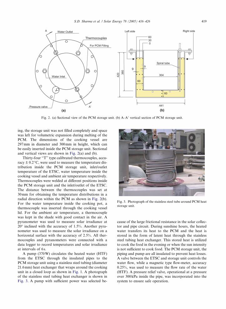
Fig. 2. (a) Sectional view of the PCM storage unit. (b) A–A 0 vertical section of PCM storage unit.
Fig. 3. Photograph of the stainless steel tube around PCM heat
storage unit.
S.D. Sharma et al. / Solar Energy 78 (2005) 416–426 419
ing, the storage unit was not filled completely and space
was left for volumetric expansion during melting of the
PCM. The dimensions of the cooking vessel are
297mm in diameter and 300mm in height, which can
be easily inserted inside the PCM storage unit. Sectional
and vertical views are shown in Fig. 2(a) and (b).
Thirty-four ‘‘T’’ type calibrated thermocouples, accu-
racy ± 0.2 �C, were used to measure the temperature dis-
tribution inside the PCM storage unit, inlet/outlet
temperature of the ETSC, water temperature inside the
cooking vessel and ambient air temperature respectively.
Thermocouples were welded at different positions inside
the PCM storage unit and the inlet/outlet of the ETSC.
The distance between the thermocouples was set at
30mm for obtaining the temperature distributions in a
radial direction within the PCM as shown in Fig. 2(b).
For the water temperature inside the cooking pot, a
thermocouple was inserted through the cooking vessel
lid. For the ambient air temperature, a thermocouple
was kept in the shade with good contact in the air. A
pyranometer was used to measure solar irradiance at
20� inclined with the accuracy of 1.5%. Another pyra-
nometer was used to measure the solar irradiance on a
horizontal surface with the accuracy of 2.5%. All ther-
mocouples and pyranometers were connected with a
data logger to record temperatures and solar irradiance
at intervals of 6s.
A pump (370W) circulates the heated water (HTF)
from the ETSC through the insulated pipes to the
PCM storage unit using a stainless steel tubing (diameter
21.6mm) heat exchanger that wraps around the cooking
unit in a closed loop as shown in Fig. 1. A photograph
of the stainless steel tubing heat exchanger is shown in
Fig. 3. A pump with sufficient power was selected be-
cause of the large frictional resistance in the solar collec-
tor and pipe circuit. During sunshine hours, the heated
water transfers its heat to the PCM and the heat is
stored in the form of latent heat through the stainless
steel tubing heat exchanger. This stored heat is utilized
to cook the food in the evening or when the sun intensity
is not sufficient to cook food. The PCM storage unit, the
piping and pump are all insulated to prevent heat losses.
A valve between the ETSC and storage unit controls the
water flow, while a magnetic type flow-meter, accuracy
0.25%, was used to measure the flow rate of the water
(HTF). A pressure relief valve, operational at a pressure
over 300kPa inside the pipe, was incorporated into the
system to ensure safe operation.

420 S.D. Sharma et al. / Solar Energy 78 (2005) 416–426
3. Phase change material (PCM)
Various materials available for energy storage in a
temperature range near 80–120 �C have been identified
for solar cooking (Domanski et al., 1995; Kakiuchi
et al., 1998; Sharma et al., 1999). The choice of the mate-
rial is based on the melting temperature, the latent heat
of fusion, density and other considerations such as tox-
icity, corrosiveness and cost. The thermo-physical prop-
erties, thermal kinetic behavior and thermal stability of
erythritol were investigated (Kakiuchi et al., 1998). We
chose commercial grade erythritol (C4H10O4) because
of its melting temperature 118 �C with high heat of fu-
sion 339kJ/kg, its low cost (US$5/kg) and large-scale
availability in the Japanese market. The erythritol used
here was procured from Mitsubishi Chemical Ltd., Ja-
pan; its thermo-physical properties are given in Table
2 and its enthalpy curve in Fig. 4.
4. Experimental results and discussion
Cooking experiments were conducted using the
ETSC and PCM storage unit. Selected results are pre-
sented in the figures to show the phase transition behav-
ior of the PCM, the water temperature inside the
cooking vessel, the heat transfer fluid temperatures and
solar irradiance. Variations of PCM temperatures with
Table 2
Thermo-physical properties of erythritol (Kakiuchi et al., 1998)
Chemical structure C4H10O4
Molecular weight 122.2
Melting point ( �C) 118.0
Heat of fusion (kJ/kg) 339.8
Specific heat
(kJ/kg�C)1.38 at (20�C) and 2.76 at (140�C)
Density (kg/dm3) 1.48 at (20�C) and 1.30 at (140�C)Heat conductivity
(W/m K)
2.64 at (20�C) and 1.17 at (140�C)
0
100
200
300
400
500
600
700
0 20 40 60 80 100 120 140 160 180 200Temperature[C]
Enth
alpy
[kJ/
kg]
Fig. 4. Enthalpy curve of erythritol.
and without load on 2, 3 and 5 September 2002 and
22 August 2003 are shown in Figs. 5–8. PCM tempera-
tures were measured at various positions in the storage
unit to ascertain the phase transition behavior. As seen
from Figs. 5–8 the collected solar energy transferred to
the PCM raises its temperature from the initial temper-
ature to the higher temperature around the melting
point. In the case of a large temperature difference be-
tween the heated water (HTF) and the PCM, the initial
change in temperature is a faster process because of the
high heat transfer rate to the PCM. After this rapid in-
crease, the temperature becomes somewhat constant
during the melting period. Similar shaped heating curves
are reported for other PCMs (Sari and Kaygusuz, 2002;
Hasan, 1994).
A test run was conducted without load on 2 Septem-
ber 2002 with an average flow rate of 6.43 l/min. The
PCM temperature distribution inside the unit is shown
in Fig. 5. The PCM maximum temperature (138 �C)was observed at TPCM(R,C,3 cm). The PCM was charged
at 1:00 PM. All PCM temperatures were more than
110 �C at 3:00 PM, which is higher than the lowest tem-
perature (near 75 �C) required for cooking most types of
food (Domanski et al., 1995; Khalifa et al., 1987).
Fig. 6 shows the variations of PCM temperatures on
3 September 2002. This experiment was undertaken to
see whether the PCM was capable of evening cooking
or not. At 5:00 PM. 10kg of water was loaded inside
the cooking vessel. The initial temperature of the loaded
water was 31.6 �C. From this figure, it can be observed
that TPCM(R,C,3 cm) suddenly dropped from 134.1 �C to
102.1 �C due to the water (1.0kg) filled in the 7mm
gap between the cooking vessel and the PCM storage
unit. At the moment when the water was filled into the
gaps, some of the water was converted into steam. Water
was put into the gap to increase the heat transfer rate
from the PCM unit to the cooking vessel. Results show
that the temperature for the load of 10kg water sharply
increased. From 6:35 PM, the temperature of the load
stayed at 100 �C. It was found that the total time for
evening cooking was 96min and that the PCM storage
unit was able to cook food in the late evening. It was ob-
served that heat transfer from the PCM to the cooking
vessel was higher due to the water that is filled in the
gap. However, this is impractical because of high
heat loss through vaporization of water and risk to the
user.
On 5 September 2002, an experiment was conducted
for noon and evening cooking with a load of 8kg water
and an average flow rate of 8.14 l/min. This experiment
was done to see the effect of noon cooking on evening
cooking. At 10:00 AM, 8.0kg of water was loaded inside
the cooking vessel for noon cooking. Temperatures of
the PCM and loaded water are shown in Fig. 7. Almost
all the PCM was melted except on the bottom. A
maximum temperature of near 130 �C was found at

25
50
75
100
125
150
9:00 10:00 11:00 12:00 13:00 14:00 15:00 16:00 17:00 18:00
Time
Tem
pera
ture
[C]
TPCM (L, T, 3cm) TPCM (L, C, 3cm) TPCM (L, B, 3cm) TPCM (R, T, 3cm)
TPCM (R, C, 3cm) TPCM (R, B, 3cm) TPCM (B, C, 3cm) Tout
Pump ON Pump OFF
Fig. 5. Variation of PCM temperatures, Tout without load on 2 September 2002.
25
50
75
100
125
150
8:00 9:00 10:00 11:00 12:00 13:00 14:00 15:00 16:00 17:00 19:00Time
Tem
pera
ture
[C]
TPCM (L, T, 3cm) TPCM (L, C, 3cm) TPCM (L, B, 3cm)
TPCM (R, T, 3cm) TPCM (R, C, 3cm) TPCM (R, B, 3cm)
TPCM (B, C, 3cm) TLoad(10kg) Tout
Pump ON Pump OFF
Fig. 6. Variations of PCM temperatures, Tout and Tload (10kg) temperatures for evening cooking on 3 September 2002.
S.D. Sharma et al. / Solar Energy 78 (2005) 416–426 421
TPCM(R, T,3 cm). At 5:00 PM, 8kg of water was loaded for
evening cooking. Results show that noon and evening
cooking on the same day is possible and daytime cook-
ing does not affect evening cooking. PCM temperatures
were found near 100 �C in the early morning (6:00 AM),
so once the food is cooked it can be kept warm until the
next morning. During this experiment, the heat transfer
rate from the PCM unit to the cooking vessel was found
to be very poor as no water filled in the gap to increase
the heat transfer, and because of the poor insulation
around the PCM storage unit. After this experiment,
urethane foam insulation was added around the PCM
storage unit to prevent heat losses.
We also tried to conduct cooking experiments in Jan-
uary 2003. All PCM temperatures were found to be less
than 100 �C in the winter experiments in spite of good
insulation around the PCM storage unit. A minimum
temperature of near 75 �C was observed inside the
PCM storage unit in winter. Thus, low temperature
cooking may be also possible in January, but the PCM
did not melt in winter for the present set-up under Jap-
anese climatic conditions.

25
50
75
100
125
150
8:00 11:00 14:00 17:00 20:00 23:00 2:00 5:00Time
Tem
pera
ture
[C]
TPCM (L, T, 3cm) TPCM (L, C, 3cm) TPCM (L, B, 3cm)TPCM (R, T, 3cm) TPCM (R, C, 3cm) TPCM (R, B, 3cm)TPCM (B, C, 3cm) Tout Tload (8kg)
Pump ON Pump OFF
Fig. 7. Variations of PCM temperatures, Tout and Tload (8kg) temperatures for noon and evening cooking on 5 September 2002.
25
50
75
100
125
150
7:00 8:00 9:00 10:00 11:00 12:00 13:00 14:00 15:00 16:00 17:00 18:00 19:00 20:00
Time
Tem
pera
ture
[C]
TPCM (L, T, 3cm) TPCM (L, C, 3cm) TPCM (L, B, 3cm)TPCM (R, T, 3cm) TPCM (R, C, 3cm) TPCM (R, B, 3cm)
TPCM (B, C, 3cm) Tout Tload (10 kg)
Pump ON Pump OFF
Fig. 8. Variations of PCM temperatures, Tout and Tload (10kg) temperatures for noon and evening cooking on 22 August 2003.
422 S.D. Sharma et al. / Solar Energy 78 (2005) 416–426
On 10 and 22 August and 4 September 2003, experi-
ments were conducted for noon and evening cooking
with loads of 5, 10 and 7kg water, the average flow rates
were 9.22, 9.32 and 8.97 l/min, respectively. Fig. 8 shows
the evolution of PCM temperatures and a water load of
10kg on 22 August 2003. The maximum PCM tempera-
ture (129 �C) was reached at TPCM(R,C,3 cm) around 1:30
PM. Almost all the PCM was melted except at the bot-
tom of the storage unit. The result shows that PCM tem-
peratures drop significantly due to the heat transfer from
the PCM to the load of 10kg water for evening cooking
at 5:00 PM. It was observed that evening cooking is fas-
ter than noon cooking for the same load, even without
filling the water in the gap to increase the heat transfer.
Cooking experiments with loads of 5 and 7kg water
were conducted on 10 August and 4 September 2003,
and the same phenomenon was observed. PCM temper-
atures, Tin, Tout, average solar irradiance and ambient
air temperature for loads of 5, 7 and 10kg water are pre-
sented in Table 3. Results show that Tmaxout varies from
130 to 135 �C around midday, and is sufficient to charge
the PCM. During the charging period, the maximum

Table
3
PCM
temperatures,Tin,Tout,averagesolarirradiance
andambientairtemperature
fornoonandeveningcooking
Date
10August
2003
22August
2003
4September
2003
Load
5kg(noonandevening)
10kg(noonandevening)
7kg(noonandevening)
Tim
e8:05
(loadin)
12:30
(loadout)
16:35
(loadin)
19:30
(loadout)
9:00
(loadin)
13:30
(loadout)
17:00
(loadin)
20:15
(loadout)
8:00
(loadin)
14:00
(loadout)
17:15
(loadin)
20:15
(loadout)
Tload
24.2
100.1
29.0
94.8
26.6
95.3
27.6
95.4
29.5
95.6
22.7
97.0
Tin
55.5
126.6
••
88.8
131.2
••
72.1
129.6
••
Tout
56.3
129.0
••
90.3
134.5
••
72.7
132.6
••
TPCM(L,C,3cm)
30.3
112.9
114.9
94.9
80.9
119.6
116.4
100.7
71.7
119.7
116.8
104.5
TPCM(R
,C,3cm)
30.2
112.9
115.7
94.0
84.6
127.4
110.7
98.8
70.8
125.2
116.9
102.0
TPCM(B,C,3cm)
30.8
85.3
107.6
90.6
65.8
106.4
110.2
93.8
77.2
104.1
110.6
95.8
Tmaxin
126.6
––
132.4
––
131.5
––
Tmaxout
129.8
––
135.8
––
135.1
––
TPCMmax
125.4
––
131.0
––
130.5
––
Ta
30.9
28.5
33.9
29.6
33.4
29.6
I h(ave)
719
––
724
––
660
––
I s20(ave)
819
––
860
––
792
––
•PumpOFF.
S.D. Sharma et al. / Solar Energy 78 (2005) 416–426 423
PCM temperature varies from 125 to 130 �C. PCM tem-
peratures are more than 110 �C at the time of evening
cooking.
Fig. 9 shows the evolution of Tout, Tin, ambient air
temperature and solar irradiance (at 20�) for typical win-ter and summer days. Tout reached its maximum of
about 138 �C around 12:45 PM in summer, compared
to 94 �C in winter at around 1:30 PM. Tout in summer
is sufficient for charging the PCM and can store only
sensible heat in winter in the Japanese climate. Solar
irradiance increases to its maximum value (1043W/m2)
at 11:00 AM in summer months and 804W/m2 in winter
months. Results show that solar irradiance and Tout are
appropriate for solar cooking with PCM storage in Jap-
anese summer months.
5. Fraction of incident solar energy stored by PCM
and water
From the measured data, we can get the fraction (f1)
during PCM charging, this is the ratio of the total stored
heat in the PCM (QPCMStored) to the solar irradiance (G),
and is defined as
f1 ¼QPCMStored
G: ð1Þ
The total heat stored in the PCM (QPCMStored) was cal-
culated by the evaluation of the enthalpy inside the
PCM storage unit. On the basis of the measured temper-
ature distribution in the PCM, we evaluated enthalpy
for each point in the PCM storage unit using the enthal-
py curve of erythritol (Kakiuchi et al., 1998). Mass (Mi)
of the PCM at each point was calculated using the
relation Mi = Viqpcm. Total heat stored in the
PCM (QPCMStored) was obtained using the following
relation:
QPCMStored ¼X21i¼1
fMiIðT iÞg: ð2Þ
Solar irradiance (G) was calculated with the following
equation:
G ¼ ðsaÞAZ t
0
Is20 dt: ð3Þ
Fraction (f2) is the ratio of the total stored heat in the
PCM (QPCMStored) to the total heat gain by the heat
transfer fluid �water� (QWaterStored), and is defined as
f2 ¼QPCMStored
QWaterStored
: ð4Þ
Total heat gain by the water (QWaterStored) was obtained
from the following relation:

0
25
50
75
100
125
150
9:00 10:00 11:00 12:00 13:00 14:00 15:00Time
Tem
pera
ture
[C]
200
400
600
800
1000
1200
Sola
r irra
dian
ce (2
0 de
gree
) [W
/m2 ]
Tout (summer) Tin (summer)Ta (summer) Tout (winter)Tin (winter) Ta (winter)Is20 (summer) Is20 (winter)TT
I
Fig. 9. Variation of Tin, Tout, Ta and Is20 with time for a typical day in summer and winter month.
424 S.D. Sharma et al. / Solar Energy 78 (2005) 416–426
QWaterStored ¼ mCw
Z t
0
ðT out � T inÞdt; ð5Þ
where ‘‘m’’ is the flow rate of the water.
Fraction (f3) is the ratio of the total heat gain by the
heat transfer fluid �water� (QWaterStored) to the solar irra-
diance (G), and is defined as
f3 ¼QWaterStored
G: ð6Þ
Fractions f1, f2 and f3 were calculated with and with-
out load on different days and tabulated in Table 4.
Fraction f3 presents the collector performance. The
ETSC showed good performance and f3 varies between
66 and 77% for loads of 5, 7, 8 and 10kg water and
71% without load. The difference between the incident
solar irradiance and the heat gain by HTF represents
the collector thermal loss. Fraction f2 showed poor per-
formance because of the insufficient heat transfer to the
PCM storage unit and heat losses through the unit. As a
result, fraction f1( = f2 · f3) also shows poor
performance.
There are several methods to enhance heat transfer in
a latent heat thermal storage unit. The use of finned
tubes in thermal storage systems with different configu-
rations has been reported by Morcos (1990) and Velraj
et al. (1999). An embedded carbon fiber brush was also
used to enhance thermal conductivity in the PCM (Fu-
kai et al., 2000). Though our experiments and analysis
indicated that the prototype solar cooker yielded satis-
factory performance in spite of low heat transfer, a mod-
ified design for the heat exchanger in the thermal storage
unit should enhance the rate of heat transfer in our pres-
ent set-up.
6. Conclusion
In the present study, the thermal performance of a
prototype solar cooker based on an ETSC with a
PCM heat storage unit was studied. A simple cylindrical
PCM heat storage unit was designed to store solar en-
ergy during sunshine hours and to cook food in the
evening. The experimental results from the present set-
up allow the following conclusion:
(i) The system is able to cook successfully twice (noon
and evening) in a single day during Japanese sum-
mer months. Noon cooking did not affect evening
cooking, and the evening cooking using the PCM
heat storage was found to be faster than noon
cooking.
(ii) The PCM did not melt in January (winter) in
Japan. In summer, PCM temperatures reached
more than 110 �C at the time of evening cooking.
Hence, erythritol is a promising PCM for solar
cooking.
(iii) Fraction f1 defined as the ratio of stored heat to
solar irradiance showed poor performance. How-
ever, cooking experiments showed that the PCM
storage unit is able to store an adequate amount
of heat for noon and evening cooking and is also
capable to keep PCM temperatures (near 75 �C)until the next morning.
This system is expensive but shows good potential
for community applications. It provides high PCM
temperatures of up to 130 �C without tracking and al-
lows cooking in the shade and also in a conventional

Table
4
ThefractionofincidentsolarenergystoredbyPCM
andwater
Date
Mload(kg)
mave(l/m
in)
QPCMStored(M
J)Q
WaterStored(M
J)G
(MJ)
f 1¼
QPCMStored
G
�� ð%
Þf 2
¼Q
PCMStored
QWaterStored
�� ð%
Þf 3
¼QWaterStored
G
�� ð%
Þ
2September
2002
Noload
6.43
12.3
39.9
56.0
21.9
30.8
71.2
5September
2002
8(twotimecooking)
8.14
10.4
40.9
61.5
16.9
25.4
66.5
10August
2003
5(twotimecooking)
9.22
8.9
40.3
56.2
15.8
22.1
71.7
22August
2003
10(twotimecooking)
9.32
9.3
35.6
46.2
20.1
26.1
77.1
4September
2003
7(twotimecooking)
8.97
8.3
36.3
52.9
15.7
22.9
68.6
S.D. Sharma et al. / Solar Energy 78 (2005) 416–426 425
kitchen during non-sunshine hours or in the evening.
Therefore, solar cookers based on an ETSC with a
PCM storage unit should help to popularize solar
cookers in Japan, as well as in other regions having
good sun shine.
Acknowledgements
The authors are grateful to the Satellite Venture Busi-
ness Laboratory, Mie University, Japan for providing
the financial support and constant encouragement for
the present study. S.D. Sharma is very grateful to Japan
Society for the Promotion of Science for funding the
post doctoral fellowship for the year 2003–2005.
References
Balzar, A., Stumpf, P., Eckhoff, S., Ackermann, H., Grupp, M.,
1996. A solar cooker using vacuum tube collectors with
integrated heat pipes. Solar Energy 58 (1–3), 63–68.
Buddhi, D., Sahoo, L.K., 1997. Solar cooker with latent heat
storage: Design and experimental testing. Energy Conver-
sion and Management 38 (5), 493–498.
Buddhi, D., Sharma, S.D., Sharma, A., 2003. Thermal perfor-
mance evaluation of a latent heat storage unit for late
evening cooking in a solar cooker having three reflectors.
Energy Conversion and Management 44, 809–817.
Domanski, R., El-Sebaii, A.A., Jaworski, 1995. Cooking during
off-sunshine hours using PCMs as storage media. Energy 20
(7), 607–616.
Fukai, J., Kanou, M., Kodama, Y., Miyatake, O., 2000.
Thermal conductivity enhancement of energy storage media
using carbon fibers. Energy Conversion and Management
41, 1543–1556.
Hasan, A., 1994. Phase change material energy storage system
employing palmitic acid. Solar Energy 52 (2), 143–154.
Kakiuchi, H., Yamazaki, M., Yabe, M., Chihara, S., Teru-
numa, T., Sakata, Y., Usami, T., 1998. A study of erythritol
as phase change material. IEA Annex 10-PCMs and
chemical reactions for thermal energy storage, second
workshop, 11–13, November Sofia, Bulgaria.
Khalifa, A.M.A., Taha, M.M., Akyurt, M., 1987. Design,
development and testing of a new concentrating type solar
cooker. Solar Energy 38 (2), 79–88.
Kumar, R., Adhikari, R.S., Garg, H.P., Kumar, A., 2001.
Thermal performance of a solar pressure cooker based on
evacuated tube solar collector. Applied Thermal Engineer-
ing 21, 1699–1706.
Morrison, G.L., Mills, D.R., 1987. Solar stove for developed
countries. In: Proc. ISES World Congress, Hamburg,
Federal Republic of Germany, pp. 13–18.
Morcos, V.H., 1990. Investigation of a latent heat thermal
energy storage system. Solar Wind Technology 7 (2/3), 197–
202.
Sari, A., Kaygusuz, K., 2002. Thermal performance of palmitic
acid as a phase change energy storage material. Energy
Conversion and Management 43, 863–876.

426 S.D. Sharma et al. / Solar Energy 78 (2005) 416–426
Schwarzer, K., Maria Eugenia Vieria da Silva, 2003. Solar
cooking system with or without heat storage for
families and institutions. Solar Energy 75, 35–
41.
Sharma, S.D., Buddhi, D., Sawhney, R.L., 1999. Accelerated
thermal cycle test of latent heat storage materials. Solar
Energy 66 (6), 483–490.
Sharma, S.D., Buddhi, D., Sawhney, R.L., Sharma, A., 2000.
Design development and performance evaluation of a latent
heat unit for evening cooking in a solar cooker. Energy
Conversion and Management 41, 1497–1508.
Velraj, R., Seeniraj, R.V., Hafner, B., Faber, C., Schwarzer, K.,
1999. Heat transfer enhancement in a latent heat storage
system. Solar Energy 65, 171–180.