THERMAL ISOLATION CLIP...THERMAL ISOLATION CLIP Installation Guide INSTALLATION BEST PRACTICE GUIDE...
6
THERMAL ISOLATION CLIP Installation Guide INSTALLATION BEST PRACTICE GUIDE The following is recommended for all wall installations: Familiarize yourself with the shop drawings. Where there is a difference between approved shop drawings and these instruc- tions, the shop drawings should be followed. Install all materials plumb, level and true. All work should start from bench marks established by the architectural drawings and the general contractor. The sequence of erection should be coordinated with the job superintendent so delays are prevented and risk of material damage is minimized. Make certain the substrate construction to which the ISO Clip is to be attached is in accordance with the contract documents. If not, notify the general contractor in writing, and resolve differences before proceeding with work. Follow installation and assembly instructions. Be sure you have all the materials & tools needed to begin the installation: Approved shop drawings Installation tools such as laser level, drill/screwgun, bits, clamps Sub-Girts, Fasteners, Insulation, Stick Pins (If required) TOOLS REQUIRED 5/16” x 6”LG Nut Setter 416-0009 C-Clamp Vise Grip Drill/Driver ISO Clip 314-0001 #10 Fastener 409-0014 #14 Fastener 409-0012 1.844.740.2050 [email protected] ISOCLIP.COM
Transcript of THERMAL ISOLATION CLIP...THERMAL ISOLATION CLIP Installation Guide INSTALLATION BEST PRACTICE GUIDE...

THERMAL ISOLATION CLIPI nstal lat ion Guide
INSTALLATION BEST PRACTICE GUIDEThe following is recommended for all wall installations:
Familiarize yourself with the shop drawings. Where there is a di�erence between approved shop drawings and these instruc-tions, the shop drawings should be followed.
Install all materials plumb, level and true.
All work should start from bench marks established by the architectural drawings and the general contractor. The sequence of erection should be coordinated with the job superintendent so delays are prevented and risk of material damage is minimized.
Make certain the substrate construction to which the ISO Clip is to be attached is in accordance with the contract documents. If not, notify the general contractor in writing, and resolve di�erences before proceeding with work.
Follow installation and assembly instructions.
Be sure you have all the materials & tools needed to begin the installation:
Approved shop drawings Installation tools such as laser level, drill/screwgun, bits, clamps Sub-Girts, Fasteners, Insulation, Stick Pins (If required)
TOOLS REQUIRED
5/16” x 6”LG Nut Setter416-0009
C-Clamp Vise Grip Drill/Driver ISO Clip314-0001
#10 Fastener 409-0014
#14 Fastener 409-0012
1.844.740.2050 [email protected]
ISOCLIP.COM

INSTALLATION
1. Set vertical and horizontal attachment lines on the substrate. On opaque membrane the vertical is identi�ed by a vertical caulk line and the horizontal line is established by a laser line With the translucent product the stud fasten-ers are visible requiring only a horizontal line to be established. Use the meth-ods that suit site conditions best. Ensure all holes in the membrane are patched according to manufactures requirements.
2. When using a laser level utilize the clip sti�ening ribs to ensure vertical align-ment. For example, on the left, the self levelling point laser is positioned so the top of the dot on the laser aligns with the top of the sti�ening rib. If the laser is setup between two installation points it is possible to work from both sides in towards the laser with this method.
3. Fasten clip to the structure using #14 self drilling fasteners as per shop draw-ings.
4. Ensure clips are level from one to another to ensure ease of sub girt installa-tion into the retaining tab.
INSTALLATION
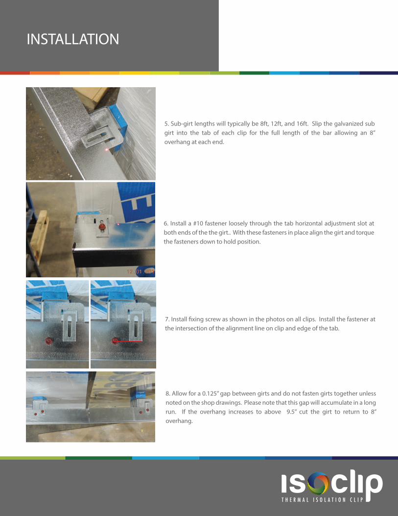
5. Sub-girt lengths will typically be 8ft, 12ft, and 16ft. Slip the galvanized sub girt into the tab of each clip for the full length of the bar allowing an 8” overhang at each end.
6. Install a #10 fastener loosely through the tab horizontal adjustment slot at both ends of the the girt.. With these fasteners in place align the girt and torque the fasteners down to hold position.
7. Install �xing screw as shown in the photos on all clips. Install the fastener at the intersection of the alignment line on clip and edge of the tab.
8. Allow for a 0.125” gap between girts and do not fasten girts together unless noted on the shop drawings. Please note that this gap will accumulate in a long run. If the overhang increases to above 9.5” cut the girt to return to 8” overhang.

STANDARD INSULATION APPLICATION
1. Align insulation with clip, using a knife cut the insulation vertically to allow the insulation to bypass the clip.
2. Install stick pins as per manufacturer’s recommendation. For ease of installation the layout shown allows for the insulation to be tucked in place. Setting the top row of stick pins at least 10 inches below the girt assists installation of the insulation.
3. Install retaining washer as per manufacturer’s instructions and bend stick pin over with pliers. During installation ensure that all insulation is �rmly compressed around the ISOClip and not loosely �tted.
4. If 2ft wide insulation batt is installed, only one cut will have to be made in each batt of insulation. Ensure all gaps between the insula-tion and substrate are �lled with mineral wool and each batt is tight to the next. Stagger vertical joints in the insulation by a minimum of 12” at sub-girt line.

1. Utilizing stick pins the insulation can also be installed before the sub girt. First install the stick pins as per the manufacturers requirements.
2. Slit/cut the insulation around the clip as required to allow the insulation to be installed. Ensure the insulation is compressed all around the ISOClip and not loosely �tted.
3. Next install the sub girt onto the clips . Adjust the sub girt to the depth required.
4. Using the fasteners set out and install the girt onto the clip as required. Continue the installation from the bottom to the top of the wall by applying the next row of insulation and sub girts. Stagger vertical joints in the insulation by a minimum of 12” at sub-girt line.
PROGRESSIVEINSULATION APPLICATION

1. Insulation should be installed in the horizontal direction. Centering the batt of insulation on a stud allows 3 columns of fasteners to be installed if required.
2. Install the insulation-batt tight to the sub girt, slit/cut and press the insulation around the clip. Ensure during the installa-tion that all batts of insulation are compressed around the ISO Clip and not loosely �tted.
3. Pop closure cap from housing and insert pin onto gun as per manufacturer’s instructions. Located pin 6” below top edge of batt and directly on the steel stud location. Use alignment of clips above or steel stud �nder to locate if necessary.
4. Close cap on pin. Use a minimum of 4 pins fasteners per full batt of insulation. Stagger vertical joints in the insulation by a minimum of 12” at sub-girt line.
PROGRESSIVEINSULATION APPLICATION
1.844.740.2050 [email protected]
ISOCLIP.COM
Alternative installation utilizing insulation fasteners.