
THERMAL INSULATION - NASA · PDF fileCoverage of thermal insulation technology ranges from...
14
NASA SP-5930 (01) THERMAL INSULATION A COMPILATION "_'_V_, _i ¸' tJ s,A. TECHNOLOGY UTILIZATION OFFICE NATIONAL AERONAUTICS AND SPACE 1970 ADMINISTRATION Washington, D.C. https://ntrs.nasa.gov/search.jsp?R=19710021375 2018-05-03T11:28:35+00:00Z
Transcript of THERMAL INSULATION - NASA · PDF fileCoverage of thermal insulation technology ranges from...

NASA SP-5930 (01)
THERMAL INSULATION
A COMPILATION
"_'_V_, _i ¸'
tJ s,A.
TECHNOLOGY UTILIZATION OFFICE
NATIONAL AERONAUTICS AND SPACE
1970
ADMINISTRATION
Washington, D.C.
https://ntrs.nasa.gov/search.jsp?R=19710021375 2018-05-03T11:28:35+00:00Z

NOTICE * This document was l)repared under the slmnsorship of the National
Aeronautics and Space Administrati(m. Neither the United States Government
nor any person acting oil behalf of tilt. United States Government assumes any
liability resulting from the use of the information contained in this document,
or warrants that such use will be fret, from privately owned rights.
For role by the National Technical Information Service, Springfield, Virginia 22151 - Price $l.00
Foreword
The National Aeronautics and Space Administration and Atomic Energy Com-
mission have established a Technology Utilization Program for the dissemination
of information on technological developments which have potential utility outside
the aerospace and nuclear communities. By encouraging multiple application ofthe results of their research and development.NASA and AEC earn for the public
an increased return on the investment in aerospace and nuclear research and devel-
opment programs.
This publication is part of a series intended to provide such technical informa-
tion. Coverage of thermal insulation technology ranges from innovative concepts to
proven insulation materials and applications. Of particular interest arc the extensive
investigations conducted by aerospace agencies in the development of insulation
systems capable of reliable performance despite minimum weight and size con-
straints. Test results, reflecting both laboratory and field evaluation of material
properties and structural capabilities, have direct transfer value to a broad segment
of industry.
Additional technical information on individual devices and techniques can be
requested by circling the appropriate number on the Reader's Service Card included
in this compilation.
Unless otherwise stated, NASA and AEC contemplate no patent action on the
Technology described.
We appreciate comment by readers and welcome hearing about the relevance
and utility of the information in this compilation.
Ronald J. Philips, Director
l'echnoloj_r Utilizativn O]]ice
Nathmal Aeronautics and .Sl_a_'e A dmini_trati<m
iii

Contents
SI_CTIOX 1. Research and Design Page
Thermal Conductivity Measurement of ttigh PerfornlanceInsulation ............................................... 1
Cryogenic Gas Storage System Thermal Protection
Design Improvemeqt ...................................... 1
Heat Barrier Coatings ..................................... 2
Cryogenic Insulation of Flexible Lines ......................... 3Heat Sitlk Evaluation: A Concept ............................ 3Low Cost External Insulation for Bulkheads .................... 4
Reflective Insulator Layers Separated by Bonded Silica Beads ...... 4
Tape Wound Cryogenic Insulation ............................ 4
Inexpensive Cryogenic Insulation Replaces VacuumJackei .................................................. 5
Storage Time Extension of Existing Cryogenic Tanks ............ 5
Manufacturing Techniques for Application of
Cryogenic Insulation ...................................... 5
A Stud), of Thermal Conductivity . ............................ 6
Cryogenic Insulation Research for Aerospace Vehicles ........... 6
Cryogenic Insulation Development ............................ 6Multi-Laminar lnsukition ................................... 7
Si!CflOX2, Insulation Systems and Components
Wire Coil Used to Form Irregular Shape Purge Channels ........ 7
Protective Coating Withstands High Temperatures
in Oxidizing Atmosphere .................................. 8
Flexible Gas Trap Insulator for Cryogenic Tanks ................ 8
Refractory Coating Protects Intricate Graph ire Elementsfrom High Temperature Hydrogen .......................... 9
Flexible Protective Coatings Made from Silicon-
Nitrogen Materials ....................................... 9
Coating Permits Use of Strain Gage in Water
and Liquid Hydrogen ..................................... 10
Hand-Operated Plug Insertion Valve .......................... 10

Section 1. Research and Design
I"HI_IRMAI. ('()NI)I:('TIVII'_ MEANURI<MENT OF ttI(;H PI_IRI-'ORMAN(T INSI:I_ATION
Longitudinal HeaterThermocouples
En_Hea,eri_ / _'_[J LongitudinalHeater ]
l Test Heater End Heater
Specimen Insulation
Thermal conductivity may be measured as a
more discrete function at temperature drops of
approximately 10 °F in comparison to 200°F levels
in previous methods. The measurement is con-
dueled across the insulation to ensure accuracy by
minimizing the longitudinal heat losses. A silicone
resin-fiberglass tube approximately 3 ft long, 3 in.
outside diameter, and a 1/16in. wall, supportsthe insulation. Five heaters, wound from 6-rail
copper heater wires, are arranged along the sup-
port tube. Tv_'o "longitudinal heaters" bracket
the test healer to simulate the infinite cylindereffect. Two "'end heaters" which are 1 in. long,
and a I ft long "'test heater" complete the unit. A
separate variable power control for each heater
ensures uniform temperatures over the entire cyl-
inder length. After insulation samples are wrapped
around the heater wires, thermocouples are posi-
tioned at both inner and outer surfaces of the spec-
imens to monitor their temperatures. Heat fluxvalues are calculated from the measured current
and voltage in the test heater. Since the internal
and external radii and length of the insulation
are known, thermal conductivity is readily cal-
culated by substituting experimental data values
into the standard log-mean temperature formula.
Source: E. H. Hyde
Marshall Space Flight Centerand L. D. Russell of
Lockheed Missiles and Space Companyunder contract to
Marshall Space Flight Center
(MFS-14088)('ircle 1 ml Reader'_ Service Card.
(R_,'O(;ENI(" GAS STORAGE .%_,'.%'1"1-i,_ITHERMAl. PROTE(TIONDESIGN IMPROVE,MENT
Significant thermal radiation protection is
afforded by the addition of a thermal shield within
the vacuum annulus in a cryogenic gas storage sys-
tem. The vapor cooled shield decreases the tem-
perature surrounding the pressure vessels since
the vapor carries away considerable heat during
periods of high flowrate. Storage of cryogenic
gas is also improved by the application of optical
design techniques to multilayer coatings of a gasstorage vessel, This additional refinement of
selectively applying absorbing, transmitting, or
reflective coatings depends upon the thermal

TttlIRM \I. INSt:LA]ION
behavior of the s),stem. Since portions of the
incident wavelengths are reflected at each of the
multiple layers, accurate sizing of the layer thick-
nesses determines the degree ol thernlal radia-tion.
Source: M.L.l)a_isand
R. K. AIIgeier. Jr.Manned Spacecraft Center
(MSC-12137)
( "if'cA"2 _nt Rcad('r'_ .Sert'h e ( ard.
o
S8
HEAT BARRII_]R ('OATIN(;S
Temperature, °F
O
O
8
\
\ \Unrestrained Thermal Expansion of
Successful development of thermal materials
and testing procedures has resulted from extensive
investigations of heat barrier coatings by aero-
space industries. The initial procedure in de-signing heat barrier coatings is the establishment
of thermal protection requirements, i.e., the ther-
mal resistance of the coating required to reduce
the heat flux through the chamber wall (in the case
of a rocket engine), and the metal surface tempera-
ture below acceptable limits. Often, selection of
an optimum thermal resistance valve is a com-
promise between the coating thickness and thethermal protection. Thick coatings are avoided
for economic reasons, convenience in coating de-
position, and most importantly, to minimize ther-
mal shock. Thermal expansion of arc-plasma
Coating Material vs Temperature
sprayed layers of graded Inconel and zirconia has
been investigated during the selection of materials
to resist stress buildup at interfaces between grad-
ed layers. A simple and inexpensive test to screen
coating systems consists of exposing a water-
cooled coated sample of a test coating to a con-
trolled arc-plasma jet at the temperatures antic-
ipated during operations. The test is limited,
however, by the small area tested and the low
shear force of plasma gases.
Source: H. W. Carpenter of
North American Rockwell Corp.under contract to
Marshall Space Flight Center
(MFS-18618)Circle 3 oH Reader's Service Card.

RISt &R(tt AND I)tSIGN 3
CRxtOGENIC INSIyI.ATION OE F'LEXIBI.E IJNES
Thermal protection for flexible metal "bel-
lows", expansion joints, and various other liquid
hydrogen (LH__) feed lines is furnished by a com-bination of insulation materials. Fibrous glass
batting is used to supply low thermal conductivity.A fluorocarbon film provides moisture protection
and is sealed to control cryopumping of the glass
batting during exposure to LH,. The final ele-
ment, a 0.003-in.-thick polyurethane-impregnated
nylon cloth, features tear resistance to rough han-
dling often encountered during assembly of ad-
jacent equipment. This insulation has the capa-
bility of remaining flexible over a temperaturerange of }300°F to-433°F, and is therefore suit-
able to insulate flexible surfaces in LH_ fucl feedlines.
Source: 1. [slamoff of
Hayes International Corp.under contract to
Marshall Space Flight Center
(MFS-13773)
Circle 4 on Reader'._ Service Card.
HEAT SINK EVALIIATION:ACONCEPT
g
lZI
FoilTempJct of Trans.
41"J
J
Mica Temp.Jct of Trans
fJ
JJ
lO 20 30 40 50 60 70 80 90 lOO 110 12o 13o 14o
Junction Temperatu re Degrees C
Heat Sink Evaluation System
Transistor junction temperatures were usedto evaluate the thermal transmission character-
istics of indium foil and mica insulation for
semiconductor'devices. :A comparison of the two
materials indicated that indium demonstrated
superior heat transfer properties. The junction
temperature of a power transistor when coupled
to a heat sink with indium foil ranged from 30 ° to
76°C over a I to 5 watt power input range. The
mica coupled transistor indicated a junction tern-
perature of 172°C at a 3 watt power input when
the test was terminated to avoid exceeding the
manufacturer's maximum junction temperature
specification of 200°C. This innovation may be
useful in semiconductor component testing andthermal-load control applications.
Source: M. C. Latham
NASA Pasadena Office
(NPO- 10843)Circle 5 o#t Reader's Service Cant.

4 THI£RM,\L INSULATIO _,
1+()%%'CO.%T EXTERNj, I. INSI;i.._'II()N F()R BII.KIIE,.%I)._
Destructive loading in the insulatic)n of large
tanks filled v, ith cryogenic liquids is avoided b_
using a reinforced foam insulation to maintain
structural integrity. The insulating procedure
starts by bonding a scrim cloth intermittently tothe tank wall. A thin coat of foam is then sprayed
on the cloth, v+hich penetrates and forms a struc-
tural foam layer attached to the _sall. Before thiscoat is completely cured, a second scrim cloth is
imbedded over the tack) foam. This process is
repeated as often as necessary to obtain the desired
thermal properties. The final cover is an impreg-nated close _,eav¢ cloth which coats and seals the
structure.Source: D. Rosselloof
McDonnell Douglas Corp.under contract to
Marshall Space Flight Center
(M FS- 12960)
Circle 6 o, Reader's Service Card.
REFI,ECflVE INSI;I, ATOR I+AYErS SEPARATED B%' BONDED SII,I('A BE._,I)N
To eliminate separate, bulky nonconductive
sheets in multilayer reflective insulation, non-
conductive separators have been bonded to themetallic reflective sheets prior to fabrication of
the end product. This eliminates the need for
separate nonconductive sheets and simplifies the
fabrication process. Previousl) used sheets of
fiberglass and similar materials presented fabrica-
tion and weight problems.
A layer of small, closeb spaced hemisphericalbeads of relatively pure silica, silicate, or other
oxide is applied to the rcx,erse side of each metal-
lic reflecting surface. Spacing and height of thebeads are related to reflector thickness. Any
desired number of treated reflectors may then be
joined by standard methods to form multilayer
reflectors tailored to the application. In one appli-
cation, 15 layers of foil treated _ith silica beads
have a total thickness of only 0.0075 inch, but arcas efficient as 0.875 inch of conventional insula-
tion.
Lithographcd aluminum foil is useful for
cryogenic applications, _hile nickel sheets flame-
sprayed with aluminum oxide function _ell at
temperatures approaching 2200°F.
tteavy-gauge reflectors mat' be used in those
applications where weight is not a consideration.In weight-sensitive applications, titanium sheets
to a thickness of 0.0001 inch tn,a 5 be cmplo._cd.Source: N.T. Zu_er, Jr. of
Grumman Aerospace Corp.under contract to
Manned Spacecraft Center( M SC-00215 )
No.l,rther docume#ttatio, i_ a vailahle.
TAPE _"OItND ('RYO(;ENIC INStil,ATI()N
Desirable cryogenic insulation properties, vent-
ing characteristics, and high-energy particle
absorption qualities are embodied in multi-
layer insulation systems. These high performance
systems feature thin, low conductivity spacersinterleaved between tape v,ound layers of I/4 rail
aluminized polyethylene terephthalate radiationshields. Manufacturers and designers of cryogenic
storage tanks, piping, and transportation facilitiescan benefit from the literature searches and labo-
ratory tests conducted and described in this tech-
nical report. Insulation materials are described in
terms of their cryogenic potential (both singly and
in combination), supported by graphs and illustra-
tions.Source: R. Burkley and
J. Stuckey of
Goodyear Aerospace Corp.under contract to
Marshall Space Flight Center
(M FS-13622)
Circle 7 +m Reader's Service ('ard.

Rt;SL,%RCH AND DESIGN
INEXPENSIVE CRYOGENI(' INSI;LATION REPLACESVACUUM JACKET
Aluminized Fiberglass Tape
_/ Cork r Polyethylene terep hthalateVapor Barrier l pAIo_mith;mene terepht halale
A capability to withstand extreme tempera-tures reaching 600 ° to 700°F in an exposed envi-
ronment is provided by this newly designed multi-
layer sealed insulation system. This insulation sys-
tem is fabricated from the following commerciallyavailable materials: cork board, adhesive, fiber-
glass tape, aluminum foil-lined fiberglass tape,
and polyethylene terephthalate-aluminum-poly-ethylene (plastic) sheath. Addition or subtraction
of insulation layers increases the system adapta-
bility to varying field requirements. Field service
of this insulation system has demonstrated that
an 8-in. cryogenic pipe line using l-in.-thick insul-
ation will have a heat leakage flow rate of approxi-
mately 109 Btu/ft "-/hr. Although _acuum jack-
etcd piping systems are nlore efficient than the
proposed unit, they are more expensive, require
special procurement of factory assembled part,,,,and are not adaptable to ficld alterations.
Source: C. E. Fuchs
Westinghouse Astronuctear Laboratoryunder contract to
Space Nuclear Propulsion Office(NUC-IO061)
Circle 8 on Reader'.s Service Card.
STORAGE TIME EXTENSION OF EXISTING CRYOGENICS TANKS
The thermal performance of it cryogenic tank
n]a) be improved through the use of a multi-
layered insulation blanket of aluminized plastic
(polyethylene terephthalate), fiberglass tension_,upport rod.,,, and stainless steel fill and vent lines.
_,:rapping the vent line around the tank before the
additkm of superinsulation provides an improve-mcnt of storage lime, but a tension member tank
_,upport addition is required for longer storageperiods.
Research has indicated that cryogenic storage
is superior to ambient storage for short periods
(up to 1300 hours in Apollo X tanks), but for long-
er periods, storage at ambient temperature and
high pressure is more economical. To obtain these
results, however, it is necessary to maintain en-
vironmental temperatures ranging from 40 ° to90°F in the tankage storage area. Higher tempera-
ture values affect the heat-leak rate and change
the density of the stored gas.
Source: G. Knowles of
Grumman Aerospace Corp.under contract to
Manned Spacecraft Center(MSC-11818)
Circle 9 on Reader's Service Card.
MANUFACTURING TECHNIQUES FOR APPLICATION OF CRYO(;ENI(" INSI;I,ATION
Detailed descriptions of preliminary design,
structural analysis of critical members, and ther-
mal analysis are given in a manufacturing pro-
cedure developed for a multilayer insulated torustank. Insulation materials were considered on the
basis of their fabrication and handling charac-
teristics as well as thermal and physical properties.
Research was conducted on silk or nylon netting,
rigid polyurethane foam, and sliced 3/4-inch poly-
ethylene terephthalate honeycomb alternatelyinterleaved with reflective shields of aluminized
polyethylene terephthalate.

6 _ttlIRM\I INSt IATION
A comprehensive manufacturing plan _as
pi-cparcd, for the ill_,ulal.ion >,ks{ell] Ct)lllponcnt'_
ol a ]()O-inch-dicuncter tortis tank _tlich cc)ntaincd
tile major tooling requirements and their applica-tion. Numerous illustrations and graphic presen-tations add to the value of this document.
Source: C. L. Lofgrcn and
D. C. Gieseking of
The Boeing Companyunder contract to
Marshall Space Flight Center(M FS- 14557)
Circle lO ou Reader'._ Service Card.
A S'l'lil)_' OF THERM
The relationship between "apparent" thermal
conductivity and temperatures for various high
performance multilayer insulation materials rang-
ing from 5[) _ to • 200°1: is documented in th> ex-
perimental stud)'. A cylindrical calorimeter wasdeveloped to measure the temperature drop after
a stead)' state heat flux was transmitted through
a one-inch-thick specimen of insulation, insula-tion materials tested included: I/4 mil single and
double aluminized plastic (polycthslenc tcrephtha-
late), fiberglass nccdles, 30-mit polyurethanefoam, and a rigid urethane foam. Conclusions
AI. ('ONliI:('TIVITY
reached from this research are presented in both
tabular and graphic format for individuals inter-
ested in insulation technology.Source: D. V. Hale,
W. H. Sims, and
J. H. Lane of
Lockheed Missiles and Space Companyunder contract to
Marshall Space Flight Center
(M FS-14351)
('ircle I 1 on Reader's Service Canl.
CRYOC, ENI(" INSULATION RESEARCH FOR AEROSPACE VEHICLES
The aerospace requirements for light but
extremely reliable cryogenic insulation systemsfocused research on high vacuum jackets; powders
under atmospheric pressure or evacuated states:
foams which were rigid or formed in place: and
structures including honeycomb, and multilayer
(with or without vacuum jacket). Insulation sys-
tems were sought which would be inexpensive,
rugged, easily repairable and convenient to han-dle. Materials and constructed forms were sub-
jected to internal and external insulation trials in
laboratory tests and scale models. Results of these
investigations are documented in both graphic andtabular form for easy transference to industrial
applications.Source: 1. lslamoff of
Hayes International Corp.under contract to
Marshall Space Flight Center
(MFS-13773)
Circle 12 or Reader'._ Service Card.
CRYO(;ENIC INSULATION DEVELOPMENT
Evaluation of several insulation systems is
based on scale model performance in test environ-
ments subjected to rapid pressure drops, accelera-
tim:, low temperatures, and acoustic noise. Con-
sideration was given to the thermal and structural
performance of multilayer insulation systems dur-
ing ground and space flight operation. Rigoroustests were conducted on a shingle-type crinkled

RESt.,\RCtl AND DISI(iN 7
aluminized plastic (polyethylene terephthalate)
insulation and also on a second type consisting of
0.030-inch foam and aluminized plastic (poly-
ethylene terephthalate). Indications of insulationfailures were evaluated and corrective measures
developed to provide the requisite reliability inthe final tests.
Although standards for space flight are nec-
essarily higher than for the majority of industrial
applications, the documented results of these
space applications should provide useful back-
ground information for makers of thermal in-
sulation products.
Source: R. C. Gethy of
General Dynamics/Astronautic_ Corp.under contract to
Marshall Space Flight Center
(M FS-14740)Circle 13 on Rea&'r'.v Service Card.
MI;I.TI-I,AMINAR INSULATION
Reflective properties required for thermal
insulation are provided by a fiberglass fabric with
one side fortified by a layer of vacuum deposited
metal. The resultant material adapts to complex
surfaces and curvatures, yet is separable for vari-
able spacing. The porosity of this reinforced fabric
permits easy evacuation of trapped gas molecules
in contra,,t to the commonly-used aluminum foil.
Additionally, the material has performed satisfac-
torily under extreme evacuation pressures of ap-
proximately 10 5torr. Based upon these desir-able features, this material should interest chem-
ical, air conditioning, and insulation designers.
Source: L. Isenburg andM. B. Hammond of
North American Rockwell Corp.under contract to
Marshall Space Flight Center
(MFS-14831)Circle 14 on Reader's Service Card.
Section 2. Insulation Systems and Components
_'IRE ('O!1, USED TO FORM IRREGULAR SHAPE PURGE ('HANNELS
inexpensive formation of irregular purgechannels around a cryogenic insulated con-
tainer may be a_zcomplished through the use of an
encased wire coil. This procedure reduces the pro-
curcmcnt of preformed parts produced by costlydie and tooling techniques. Chilldown require-
ments, prior to filling a cryogenic tank and leak
detection searches after filling, require purgechannels of several locations between the insula-
tion and the tank wall. Formation of these chan-
nels is especially difficult around the large fluid
ducts leading to the tank which normally requires
thick insulation for super-cold liquids. Coils of
w,ire (approximately 0.4-in.-inner diameter) are
covered with a resin impregnated fabric, and plac-
ed along contours where purge channels are re-
quired to form a conduit for gas flow. Gas at low
pressure is then introduced for cooling and de-
tection of possible tank leakage.Source: C. D. Crouse of
North American Rockwell Corp.under contract to
Marshall Space Flight Center
(MFS-16381)Circle 15 on Reader'._ Service Card.

THERMAL INSULATION
PROTI.I('TIVE COATING V_TI'HSTANDS HIGH TEMPERAT/:RES
IN OXIDIZING ATMOSPHERE
A plasma-arc sprayed mixture of hafnium oxide
and zirconium diboride provides a protective
coating that will withstand high temperatures in
an oxygen-rich atmosphere. Used on a thermo-
couple, it does not degrade response time and it
protects the base material a sufficiently long time
for proper temperature measurement.
A mixture of hafnium oxide and zirconium
diboride in a 1:1 ratio based on the atomic _eight
of the metal is prepared with a particle size distri-
bution of between approximately -125 and +325
mesh and an average particle size of about 200
me,_h. The powdered mixture is dispersed in an
inert gas that passes through an electrical dis-
charge arc at a typical temperature of 3000 ° to
5000°K. The resultant plasma jet is a hot, fluid,
gaseous stream and is directed ronsard the sub-
strate to be coated, this being surrounded by a
cooling atmosphere of an inert gas such as argon.
The plasma jet stream condenses on the cooled
substrate surface to provide the desired protective
coating.
A coating on the order of 0.002 to 0.050 inch
on a homogeneous tungsten thermocouple surface
gave good protection, did not flake or crack on
subsequent cooling and reheating, and did not
degrade the thermocouple response time.
This coating withstood a temperature of 4700°F
for 5 minutes with no apparent damage to the sub-
strate. Exposure to 3700°F for 30 minutes gave
the same result.
Patent status:
Title to this invention has been waived under
the provisions of the National Aeronautics and
Space Act (42 U.S.C. 2457 (f)), to Fenwal Incor-
porated, Ashland, Massachusetts.
Source: Marshall Space Flight Center
( M F S-00529)
FIJ£XIBLE (;AS TRAP INSI.II.ATOR
InsulationFuel
Outlet
Gas
Normally
Trapped
Wasted
Fuel
Movement (Adl usted
- to Requirements)
oining Structure
Inexpensive cryogenic tank insulation may' be
provided by a gas trap utilizing hydrogen (H2).
As shown in the diagram, Cavity "A" is insulated
FOR CRYOGENIC TANKS
in the bolting ring area to minimize heat transfer
from liquid oxygen (LOX) to hydrogen.This proc-
ess employs liquid hydrogen (LH_,) gasification.
LH 2 flows to the bottom of Cavity "B", then
rises to the top of the trap. As the liquid spills over
the edge it drops to the warm surface at the bot-
tom of the crevice. At this point it changes to agas
and extends a pressure downward from the top of
the trap. This pressure balances the LH 2 heat,
keeps Cavity "A" empty to retard heat flow,
and further reduces the unstable Lit2 volume
below the outflow lines.
This innovation saves the fuel ordinarily lost
in small insulated crevices, provides a means of
retrieving loose items accidently dropped into the
tank, and can also be made movable to fit a mobile
mechanism within or adjoining a cryogenic tank.
Source: R. C. Englehart of
North American Rockwell Corp.
under contract to
Marshall Space Flight Center
(M FS-13340)Circle 16 o, Rea(terL_ Service Card.
INSUI_ATION SYSTI-.MS ANt) COMPONENTS 9
RFFR _.(T()R_ r (()..VIIN(; PROTECTS INTRI(ATF; (;RAI'HITE EI_EMF;\I%
FROM tll(,lt TEMPF.R:VrIRI.; It_I)RO(;EN
In one application of [111induction furnace,
graphite heater elements must operate at tempera-
turcs [is high as 3500°F for lit least 1/2 hour in
a hydrogen atnlosphere. Uncoated graphite ele-
ments [Ire damaged lit temperatures above ap-
proximately 2500°[ :. Intricate shape of the ele-
ments prevented application of a refractor)
coating b) vapor dcposition. A composition con-
taining poundered tungsten has been developed
and can be painted on the graphite elements and
heat treated to form a tightly adherent 3-rail-
thick refractory coating.
The graphite heater elements are painted _ith
a thin coat of a mixture containing the following
ingredients, in parts by_eight: 10 to 30 tungsten
powder (325 mesh}, 2 carbon black, 9 commer-
cially available phenol-formaldehyde varnish or
paint, and 0.4 maleic anhydride. The coated parts
are then cured in air o,,er the following time-
tenlperature c}cle: fronl roonl temperature to
100°C in I hour, at 100°C for 1/2 hour, and from
100 ° to 250°C in 3 hours at the rate of 50°C perhour. tollo_ing the curing cycle, the coated heater
elements arc baked in a 10 -_ torr vacuum while
the temperature is raised from roonl temperature
to 850°C at the rate of 50°C per hour. The coated
parts are then connected as electrical resistixe
loads in an atmosphere of pure methane and sup-
plied for 2 minutes with 216 watts of po_cr pcr
square inch of exposed area. This treatment pro-duces a carbonaceous crust, which is brushed off
after the power is turned off. The process is com-
pleted by placing the parts in an atmosphere
consisting of hydrogen and nlethane (5% by.
volume) at 200 psia and applying the electrical
power at a rate increasing steadily from 226 watts
to 344 watts per square inch in one hour.A coating of 3 mils thickness heated to 4000°F
has withstood a hydrogen atmosphere for half
an hour, with no apparent degradation. This pro-
cess, which is simpler and less costly than the
vapor deposition process, can be used to protect
graphite parts for induction furnaces. It may also
have application in semiconductor technology.
Source: C.E. VogeI, J. R. Ferris,R. L. Patterson, and R. J. Steffen of
Westinghouse As'ronuclear Laboratoryunder contract to
Space Nuclear Propulsion Office( N U C-00027)
Circh' / 7 o, Reader's Service Card.
FI.EXIBI,E I'R(YiECTIVE ('()ATIN(;N MAI)E
Two substances have been successfully used as
protective coatings that withstand elevated tem-
peratures for long periods while retaining their
flexibility. They are: a polymer obtained as a
byproduct in the preparation of hexaphenyl-
cyclotrisilazane and a polymer obtained by heat-
ing bis(methylamino)-diphenylsilane.
The first substance is produced by treating
diphcnyldichlorosilane with ammonia and evapor-
ating the mother liquors after the crystalline
hexaphcnylcyclotrisilazane has been separated
by filtering. The resinous byproduct forms the
protective coating after curing briefly at 300°C.
The second substance is produced by heating
bis(methylamino)diphenylsilane at 315 ° to 320°C
for t_&rohours and removing the resultant crystals
by centrifugation. The remaining liquid byproduct
forms the protective coating after brief heating titelevated temperatures.
FROM ,_,ILI('ON-NITRO(;EN MATERIAI.S
Aluminum panels treated v, ith the first coating
and cured for one hour at 300°C _ere visibly
unaffected by one hour in boiling water. Placed
in a 19% hydrochloric acid solution, the coatedareas _.ere still unaffected _hen uncoated areas
were black and deeply etched. The second coating,on stainless steel, did not crack when the panel
was bent repeatedl> after having been heated at500°C for an hour.
Patent status:
Title to this invention has been waived under
the provisions of the National Aeronautics and
Space Act (42 U.S.C. 2457 (f)), to the Southern
Research Institute, 2000 Ninth Avenue South,
Birmingham, Alabama.
Source: Marshall Space Flight Center
( M FS-00528)
l0 TtltiRMAL INSULATION
('()ATIN(; PERMITS |SE OF STR,,_.IN (;A(;l( IN SV.VIER ANI) 1.10[11) H_I)RO(;EN
Strain gage nlea>urements had to be made in
_ater and subsequently in liquid hydrogen. Pre-
viously, a separate strain gage was used for eachmeasurement because no single strain gage
installation could bc used successfull} in both
environments. Now, a ne_ approach has resulted
in a single strain gage to make both nleasurements
sequentially. The foil strain gage used is bonded
_ith a modified heat-curing epoxy, cement and
covered with a 3-layer coating of conlmcrciall}
ax,ailable protective materials.The surface on which the gage is to be mounted
is first subjected to a thorough cleaning and abrad-
ing treatment. A drop of distilled water will flowfreely on a properly prepared surface.
A l-rail precoat of a modified heat-curing epoxy
resin is applied to the prepared surface and al-
lowed to dr}' for 4 hours. A I-nail coat of this resin
is applied over the precoat, and the gage and tabs
are positioned on the coated surface. The instal-[ation is then cured for 4 hours at 22501 • under
5 psi clamping pressure. Leads from insulatedwires are soldered to the tabs. A small dab of the
epoxy resin is used to bond the lead _ires to the
test specime n.A l-rail coat of a flexible nitrile rubber is
brushed over the entire gage and tab area and oxer
the lead _ircs. This coat is aiR)wed to dr_ for
15 minutes. A l-rail coat c)f a quick-drying resin
is applied over the same area and allowed to air-
dr}' for 15 minutes. The last step in the instalkttion
procedure is to apply a thin coat of a silicone
waterproofing lacquer over the air-dried resin.When the gage installation is immersed in
liquid hydrogen, the outer silicone lacquer pro-
tective layer may develop cracks, _,hich will
destroy its waterproofing characteristics. There-fore, when the gage is to be used for strain meas-
urements in water and in liquid hydrogen, themeasurements in water must be made first.
Source: B.B. Bervenof
North American Rockwell Corp.under contract to
Marshall Space Flight Center(M FS-00594)
Circle IS o, Reader's Service Card.
HAND4)PERATEI) PIJu!G
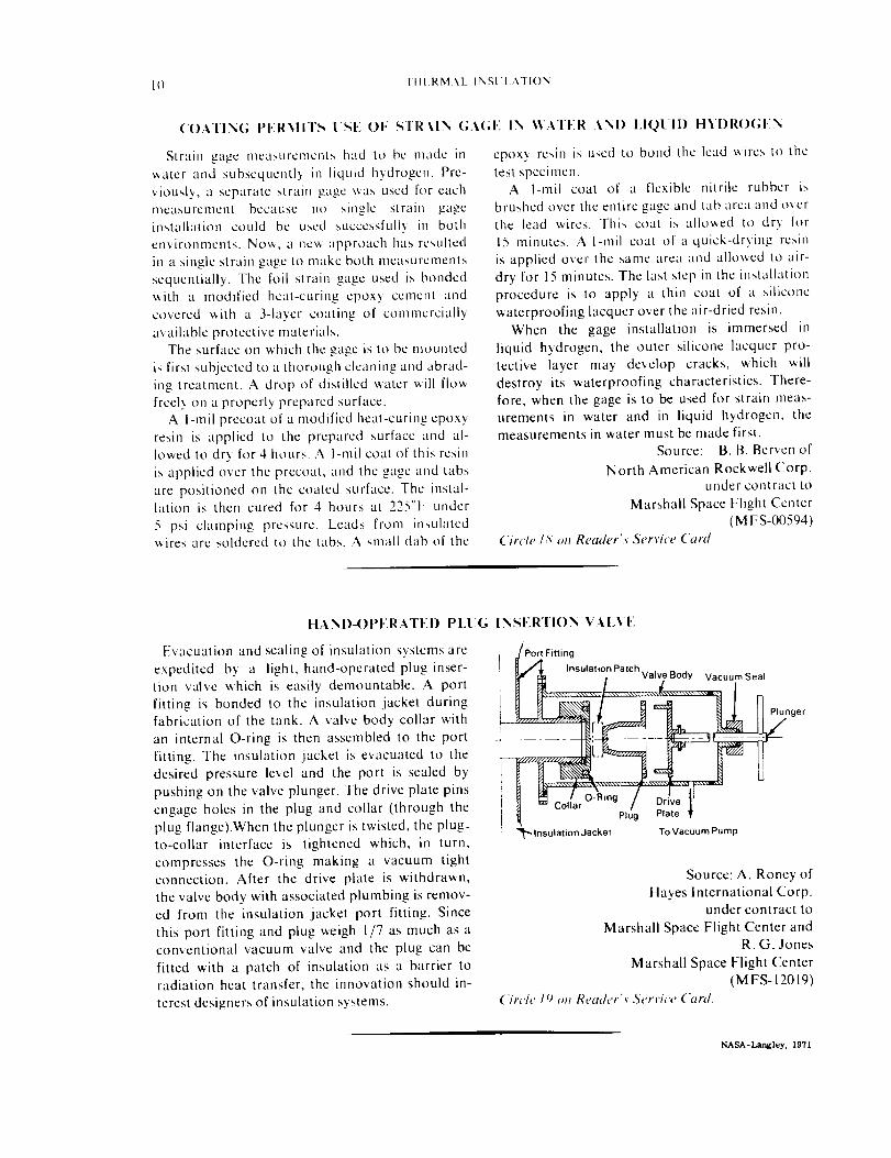
Evacuation and sealing of insulation systems are
expedited by a light, hand-operated plug inser-
tion valve which is easily demountable. A port
fitting is bonded to the insulation jacket duringfabrication of the tank. A valve body collar with
an internal O-ring is then assembled to the port
fitting. The insulation jacket is evacuated to the
desired pressure level and the port is sealed by
pushing on the valve plunger. The drive plate pins
engage holes in the plug and collar (through the
plug flange).When the plunger is twisted, the plug-to-collar interface is tightened which, in turn,
compresses the O-ring making a vacuum tightconnection. After the drive plate is withdrawn,
the valve body with associated plumbing is remov-ed from the insulation jacket port fitting. Since
this port fitting and plug weigh 1/7 as much as aconventional vacuum valve and the plug can be
fitted with a patch of insulation as a barrier toradiation heat transfer, the innovation should in-
terest designers of insulation systems.
IN SERTION VA I.VE
Port Fitting
[_ A Insulation Patch
r,_ ....... , ....... Valve Body Vacuum Seal
, ................. ger
+#u[_ _ Coliar"" / DriveIPlug Plate •
"_lnsulation Jacket To Vacuum Pump
Source: A. Roney of
Hayes International Corp.under contract to
Marshall Space Flight Center andR. G. Jones
Marshall Space Flight Center
(MFS-12019)
Circle 19 ,m Reader'._ Service Card.
NASA-Langley, 1971