Thermal Fatigue Resistance of Alloy 718 for Aluminum Die ... · PDF fileTHERMAL FATIGUE...
11
THERMAL FATIGUE RESISTANCE OF ALLOY 718 FOR ALUMINUM DIE CASTING DIES Michael M. Antony and John W. Smythe Allvac, an Allegheny Technologies Company 2020 Ashcraft Avenue Monroe, North Carolina 28 110 b Abstract Hot-work die steels have enjoyed extensive use as casting dies for over 70 years. Casting dies are typically made of H-13 when the die temperature remains below about 800°F (427°C). When the die temperature exceeds 800°F (427"C), the selection of a die material must be made from a relatively limited range of high-strength maraging steels or modified H-13 alloys. The performance of aluminum casting dies is particularly troublesome because the casting temperatures often exceed the capability of current die materials. As a result, dies invariably fail by thermal fatigue. Nickel-base superalloys have never received serious consideration as die materials because of high raw material costs and poor thermal properties. The increased awareness of die life makes alloys, such as 718, attractive from a life-cycle cost point of view. Recent investigations at Allvac, an Allegheny Technologies company, have shown that over a range of conditions, 7 18 offers significantly better thermal fatigue resistance compared to H- 13. Further, 718 appears better able to tolerate high temperature exposures during aluminum die casting. The excellent high temperature strength and oxidation resistance of 718 cofibine for excellent thermal fatigue resistance. Thermal fatigue test results and microstructural evaluations of test specimens are summarized and discussed in this paper. Superalloys 718, 625, 706 and Various Derivatives Edited by E.A. Loria TMS (The Minerals, Metals R: Materials Society), 2001
Transcript of Thermal Fatigue Resistance of Alloy 718 for Aluminum Die ... · PDF fileTHERMAL FATIGUE...
THERMAL FATIGUE RESISTANCE OF ALLOY 718 FOR ALUMINUM DIE CASTING DIES
Michael M. Antony and John W. Smythe
Allvac, an Allegheny Technologies Company 2020 Ashcraft Avenue
Monroe, North Carolina 28 1 10
b Abstract
Hot-work die steels have enjoyed extensive use as casting dies for over 70 years. Casting dies are typically made of H-13 when the die temperature remains below about 800°F (427°C). When the die temperature exceeds 800°F (427"C), the selection of a die material must be made from a relatively limited range of high-strength maraging steels or modified H-13 alloys. The performance of aluminum casting dies is particularly troublesome because the casting temperatures often exceed the capability of current die materials. As a result, dies invariably fail by thermal fatigue. Nickel-base superalloys have never received serious consideration as die materials because of high raw material costs and poor thermal properties. The increased awareness of die life makes alloys, such as 718, attractive from a life-cycle cost point of view. Recent investigations at Allvac, an Allegheny Technologies company, have shown that over a range of conditions, 7 18 offers significantly better thermal fatigue resistance compared to H- 13. Further, 718 appears better able to tolerate high temperature exposures during aluminum die casting. The excellent high temperature strength and oxidation resistance of 718 cofibine for excellent thermal fatigue resistance. Thermal fatigue test results and microstructural evaluations of test specimens are summarized and discussed in this paper.
Superalloys 718, 625, 706 and Various Derivatives Edited by E.A. Loria
TMS (The Minerals, Metals R: Materials Society), 2001
Introduction
Die castings are produced by injecting molten metal under pressure into the cavity of a metal mold or die. The cavity imparts shape to the solidifying metal. There are four principal alloy systems which are commonly die cast. These include zinc, magnesium, aluminum, and copper (brass), with approximate casting temperatures of 800°F (427"C), 1200°F (649"C), 1250°F (677"C), and 1780°F (971°C), respectively. The performance of casting dies depends upon a number of factors, including casting temperature, geometry, and casting speed. In general, higher casting temperatures, greater cavity complexity, and higher casting speeds degrade casting die performance. The performance of aluminum casting dies is particularly troublesome because the casting temperatures slightly exceed the capability of current die materials. Dies invariably fail by thermal fatigue or heat checking where small cracks develop on the die surface after repeated thermal cycling. This is a major deficiency of current alloys.
The casting die is generally produced by machining or forming a die block. Materials for casting dies must resist thermal fatigue, stress corrosion cracking, and softening at elevated temperatures. Thermal fatigue leads to fine cracks on the die surface which can cause rejection of the casting. Stress corrosion cracking and corrosion fatigue can lead to catastrophic failure of the die and in most cases, stress corrosion starts at water cooling lines (1). Resistance to softening at elevated temperatures is necessary to prevent thermal fatigue as well as erosion during the injection of molten metal.
Casting dies are typically made of hot work tool steels when the die temperature remains below about 800°F. The most commonly used hot-work die steel is H-13 (0.4C-5.25Cr-1.5Mo-1 .OV- balance Fe). In fact, H-13 has been used as a die material for over 70 years. Hardness typically ranges from HRc 42-50, depending upon the die, heat treatment and the alloy being cast. When the die temperature exceeds 800°F (427"C), the selection of a die material must be made from a relatively limited range of high-strength maraging steels or modified H-13 alloys. Nickel-base superalloys have never received serious consideration as die materials because of high raw material costs and poor thermal properties. The increased awareness of die life make more exotic alloys such as 718 attractive from a life-cycle cost point of view (2). Die life is typically measured in 'shots' or number of parts, and 20,000 to over 200,000 parts per die are considered normal. Thermal fatigue is generally regarded as the most important failure mode which limits die life, and premium quality H-13 steel provides the general benchmark for thermal fatigue resistance.
Alloy 71 8 (.08C-19.OCr-3.OMo-0.9Ti-0.5A1-5.3Cb+Ta-balance Ni) has been used for many years as a die material in hot working applications such as isothermal forging and hot die forging. The ability of wrought 718 to provide structural integrity at elevated temperatures makes it attractive as a hot forging die material. The primary reason for rejecting hot forging dies is die wear, and thermal fatigue cracking or heat checking is the second most common reason for rejection (3). Thermal fatigue results from the repeated thermal cycling of the hot forging operation. Once thermal fatigue cracks form, forging pressures will cause them to grow until eventually the die will break.
During forging or die casting, thermal stresses are generated when the surface expands upon heating and the subsurface remains constrained at a lower temperature. Most mechanistic approaches to thermal fatigue suggest some variety of the following relationship:
where A = temperature difference between the die surface and subsurface o = thermal stress E = modulus of elasticity a = coefficient of thermal expansion T = temperature
In theory, calculations of thermal stresses can provide a rational basis for predicting die material behavior. The magnitude of the thermal stress depends primarily upon the maximum temperature difference (A = Tmax - T,,,) of the die. This generalized relationship confirms an intuitive precept in die casting and hot forging: thermal fatigue cracking is reduced by decreasing Tmax - T,,,. It is common practice to preheat dies prior to hot working, hot forging, and die casting. The tendency for thermal fatigue cracking can be reduced by either raising Tmin or lowering Tmax. Studies have shown that lowering Tmax is a much more effective way of extehding die life (4).
Elasticity and the coefficient of expansion are not fixed properties; but rather, they depend upon temperature. Equation (1) can be expanded as follows:
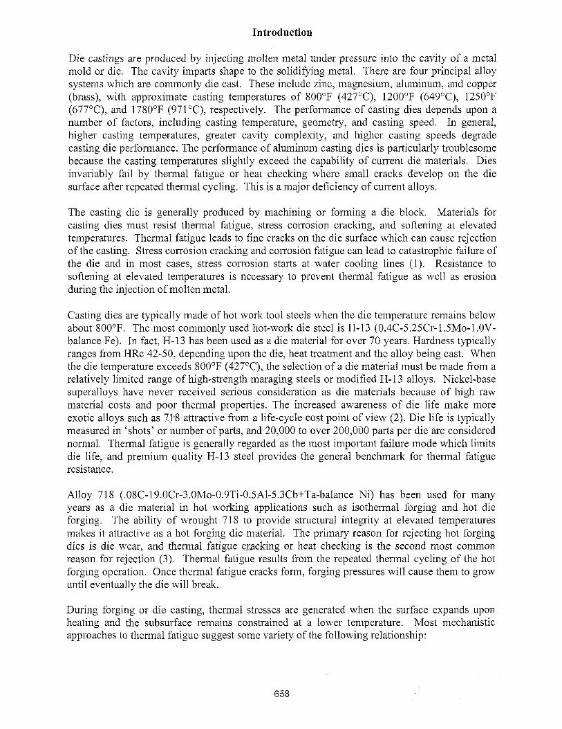
Typical thermal and mechanical property values of 718 and H-13 are listed in Table I. To a first approximation, H- 13 offers better thermal fatigue resistance (lower stress) than 7 18. However, exposures at high temperatures can cause decreases in yield strength. Figure 1 plots yield strength versus temperature, and it shows that H-13 is unable to retain strength above 800°F (427°C). Alloy 718, on the other hand, is able to retain strength up to 1200°F (649°C). For this reason, 718 offers exceptional opportunity for aluminum die casting dies, especially for applications where die temperatures exceed 800°F (427OC).
I
Table I. Estimates of Thermal Stresses in H-13 and 7 18
The data also demonstrates that H-13 dies will eventually fail by thermal fatigue provided the exposure temperature is sufficient to decrease yield strength. Eventually, the difference in expansion between the surface and subsurface will cause plastic deformation at the surface, resulting in cracking on cooling. The high strength of 718 offers the possibility for extremely long die life provided Tmax - Tmin is sufficiently small.
1 Alloy
Recent investigations at Allvac (an Allegheny Technologies company) have shown that the interaction of the alloy and the surrounding environment plays an important role in thermal fatigue crack initiation (5-7). Cracks appear to initiate in surface oxide layers and then penetrate the underlying material. In many cases, oxidation at crack tips appeared to aggravate thermal fatigue cracking. Similar effects have been observed with superalloys during high-temperature, high-cycle fatigue (8). Superalloys can exhibit significantly lower high-cycle fatigue lives in air compared to vacuum due to oxygen absorption at the crack tip.
Static Modulus (x l o 6 ksi) 200°F 1 800°F I 1000°F
Expansion (x inlin°F) 200°F 1 800°F 1 1000°F
Thermal Stress (ksi) 200°F-800°F 1200"~-1000"~
0 200 400 600 800 1000 1200 1400
Test Temperature (deg F)
Figure 1: High-temperature yield strength of 71 8 and H-13.
This paper describes the development of ~ l l v a c @ 71 8 alloy for aluminum casting dies. The objectives of this investigation were to evaluate and compare Allvac 718 alloy with H-13 for:
Thermal fatigue resistance Hardness Crack initiation Crack growth ,
Procedure
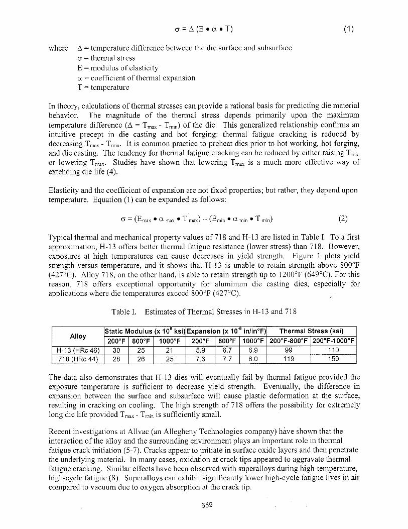
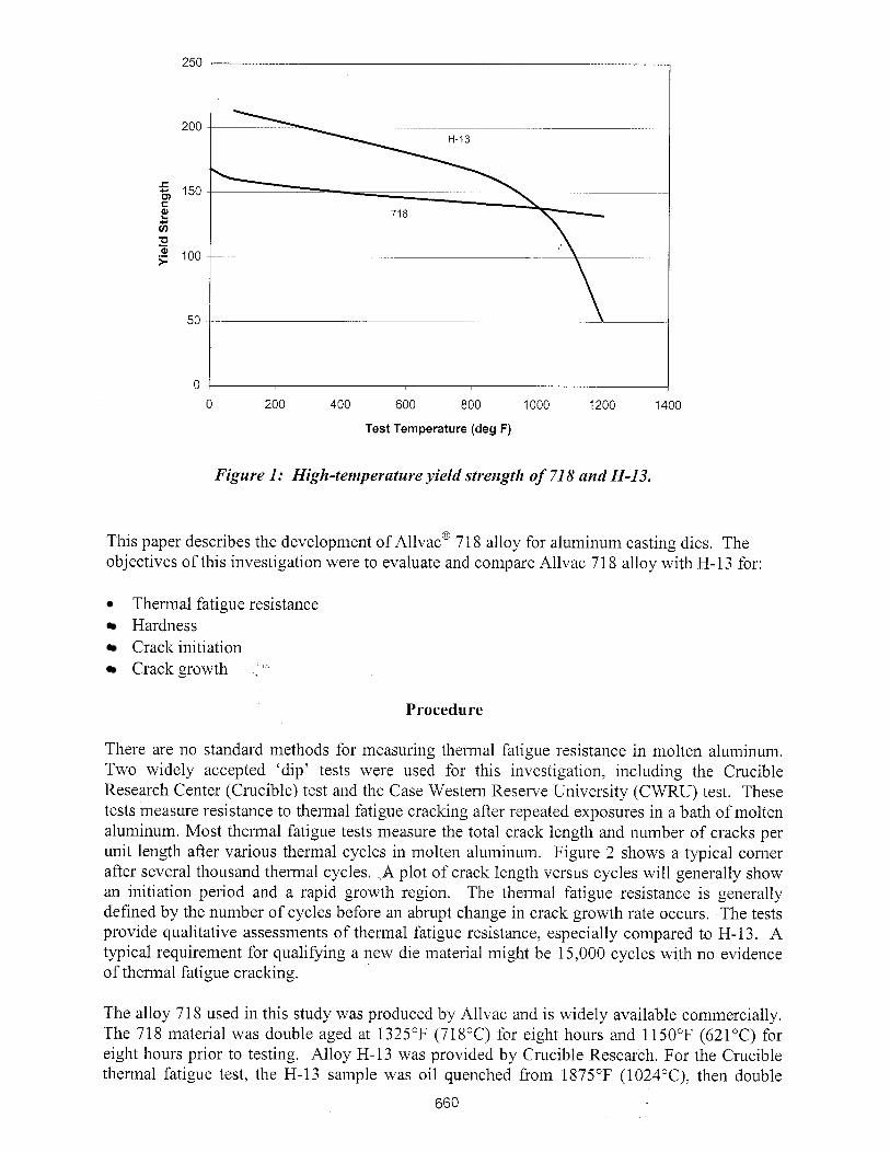
There are no standard methods for measuring thermal fatigue resistance in molten aluminum. Two widely accepted 'dip' tests were used for this investigation, including the Crucible Research Center (Crucible) test and the Case Western Reserve University (CWRU) test. These tests measure resistance to thermal fatigue cracking after repeated exposures in a bath of molten aluminum. Most thermal fatigue tests measure the total crack length and number of cracks per unit length after various thermal cycles in molten aluminum. Figure 2 shows a typical comer after several thousand thermal cycles. A plot of crack length versus cycles will generally show an initiation period and a rapid growth region. The thermal fatigue resistance is generally defined by the number of cycles before an abrupt change in crack growth rate occurs. The tests provide qualitative assessments of thermal fatigue resistance, especially compared to H-13. A typical requirement for qualifying a new die material might be 15,000 cycles with no evidence of thermal fatigue cracking.
The alloy 71 8 used in this study was produced by Allvac and is widely available commercially. The 718 material was double aged at 1325°F (718°C) for eight hours and 1150°F (621°C) for eight hours prior to testing. Alloy H-13 was provided by Crucible Research. For the Crucible thermal fatigue test, the H-13 sample was oil quenched from 1875°F (1024"C), then double
tempered at 1 100°F (593°C) for one hour. Prior to Crucible testing, the finished specimens were heated to 700°F (371°C) in air for one hour, and air cooled to room-temperature. This produced a thin oxide skin that resisted sticking of the molten aluminum.
Figure 2: SEM micrograph of typical thermal fatigue crack (arrow) in H-13.
Crucible Test
The Crucible test, as sketched in Figure 3, uses a solid, 0.512 in. x 0.512 in. x 6.023 in. (13 rnrn x 13 mm x 153 mm) test sample which is intermittently exposed to molten aluminum and water. Six samples can be tested at one time, providing a good comparison under identical test conditions. The molten A384 aluminum alloy (3.8Cu-12.0%-A1) is maintained at a temperature of 1250°F (677°C). The samples are initially immersed in molten aluminum for 7 seconds, then transferred to a water bath for 10 seconds. The samples are then dried over the molten aluminum bath for 5 seconds. This completes one cycle.
Heat (7 secs.) Water Quench (10 secs.) - Dry (5 secs.)
Figure 3: Crucible molten aluminum thermal fatigue test.
After every 5000 cycles, the samples are removed from the holding plate for examination. Two opposite faces are hand polished on a granite surface block, and each comer of the sample is
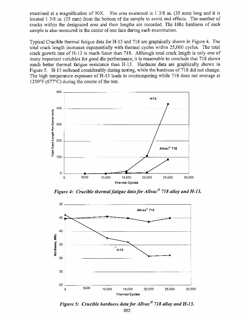
examined at a magnification of 90X. The area examined is 1 318 in. (35 mm) long and it is located 1 318 in. (35 mm) from the bottom of the sample to avoid end effects. The number of cracks within the designated area and their lengths are recorded. The HRc hardness of each sample is also measured in the center of one face during each examination.
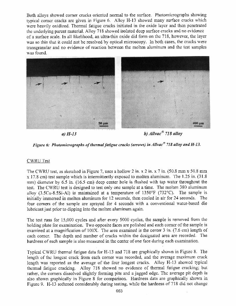
Typical Crucible thermal fatigue data for H-13 and 718 are graphically shown in Figure 4. The total crack length increases exponentially with thermal cycles within 25,000 cycles. The total crack growth rate of H-13 is much faster than 718. Although total crack length is only one of many important variables for good die performance, it is reasonable to conclude that 71 8 shows much better thermal fatigue resistance than H-13. Hardness data are graphically shown in Figure 5. H-13 softened considerably during testing, while the hardness of 71 8 did not change. The high temperature exposure of H-13 leads to overtempering while 718 does not overage at 1250°F (677°C) during the course of the test.
0 5000 10,000 15,000 20,000 25,000 30,000
Thermal Cycles
Figure 4: Crucible thermal fatigue data for ~ l l v a c " 718 alloy and H-13.
0 5000 10,000 15,000 20,000 25,000 30,000
Thermal Cycles
Figure 5: Crucible hardness data for dllvac" 718 alloy and H-13. 662
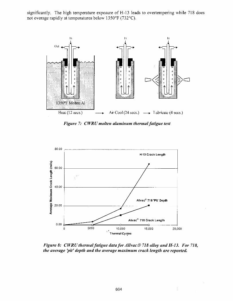
Both alloys showed comer cracks oriented normal to the surface. Photomicrographs showing typical comer cracks are given in Figure 6. Alloy H-13 showed many surface cracks which were heavily oxidized. Thermal fatigue cracks initiated in the oxide layer and then penetrated the underlying parent material. Alloy 71 8 showed isolated deep surface cracks and no evidence of a surface scale. In all likelihood, an ultra-thin oxide did form on the 718, however, the layer was so thin that it could not be resolved by optical microscopy. In both cases, the cracks were transgranular and no evidence of reaction between the molten aluminum and the test samples was found.
a) H-13 b) ~ l l v a c @ 71 8 alloy
Figure 6: Photomicrographs of thermal fatigue cracks (arrows) in ~ l l v a c @ 718 alloy and H-13.
CWRU Test
The CWRU test, as sketched in Figure 7, uses a hollow 2 in. x 2 in. x 7 in. (50.8 mm xr50.8 mm x 17.8 cm) test sample which is intermittently exposed to molten aluminum. The 1.25 in. (31.8 mm) diameter by 6.5 in. (16.5 cm) deep center hole is flushed with tap water throughout the test. The CWRU test is designed to test only one sample at a time. The molten 380 aluminum alloy (3.5Cu-8.5%-A1) is maintained at a temperature of 1350°F (732°C). The sample is initially immersed in molten aluminum for 12 seconds, then cooled in air for 24 seconds. The four comers of the sample are sprayed for 4 seconds with a conventional water-based die lubricant just prior to dipping into the molten aluminum again.
The test runs for 15,000 cycles and after every 5000 cycles, the sample is removed from the holding plate for examination. Two opposite faces are polished and each comer of the sample is examined at a magnification of 100X. The area examined is the center 3 in. (7.6 cm) length of each comer. The depth and number of cracks within the designated area are recorded. The hardness of each sample is also measured in the center of one face during each examination.
Typical CWRU thermal fatigue data for H-13 and 718 are graphically shown in Figure 8. The length of the longest crack from each comer was recorded, and the average maximum crack length was reported as the average of the four longest cracks. Alloy H-13 showed typical thermal fatigue cracking. Alloy 718 showed no evidence of thermal fatigue cracking; but rather, the comers dissolved slightly forming pits and a jagged edge. The average pit depth is also sfiown graphically in Figure 8 for comparison. Hardness data are graphically shown in Figure 9. H-13 softened considerably during testing, while the hardness of 718 did not change
significantly. The high temperature exposure of H-13 leads to overtempering while 71 8 does not overage rapidly at temperatures below 1350°F (732°C).
Out +-
1
Heat (12 secs.) Air Cool (24 secs.) ---, Lubricate (4 secs.)
Figure 7: CWRU molten aluminum thermal fatigue test
80.00
H-13 Crack Length
0 5000 10,000 15,000 20,000
Thermal Cyejes
- - .- 5 60.00 - 5 m Q
Y 0
b 40.00
5 E .- X
I" & 20.00 f 4
0.00
Figure 8: CWRU thermal fatigue data for AllvacB 718 alloy and H-13. For 718, the average jpit' depth and the average maximum crack length are reported.
~ l l v a c @ 71 8 'Pit' Depth
~ l l v a c @ 71 8 Crack Length
p " - "
Thermal Cycles
Figure 9: C WRU hardness data for Allvac@ 71 8 alloy and H-13.
Figure 10 shows a typical comer pit in alloy 718. SEM analysis of various pits showed evidence of intermixing and the formation of Ni-A1 intermetallics. The binary Ni-A1 eutectic forms at 1184°F (640°C) while the Fe-A1 eutectic forms at 121 1°F (655°C). Attempts were made to measure the comer temperature by embedding a thermocouple into a hole drilled adjacent to the comer. Surprisingly, peak temperatures measured 1040°F (560°C) for 71 8 and 1 100°F (593°C) for H- 13. Obviously, long-time exposures between molten aluminum and any nickel- or iron-base alloy will result in dissolution, so the best practice is short exposure times at low temperatures.
Figure 10: Photomicrograph of corner pits in AZlvac@ 71 8 alloy.
Discussion
The performance of casting dies depends upon a number of factors, including: yield strength, coefficient of expansion, maximum difference in die temperature, hardness, toughness, oxidation behavior, and microstructural stability. In general, high yield strength, low coefficient of expansion, minimum differences in die temperatures, resistance to softening, high toughness, oxidation resistance, and stable microstructures are preferred for improved die performance. Alloy H-13 offers a variety of attractive attributes; however, it lacks resistance to softening and oxidation resistance. The oxide scales which form on H- 13 are non-protective and H- 13 softens rapidly above 800°F (427°C). This combination will eventually lead to thermal fatigue cracking depending upon the die temperature and number of cycles. Alloj H-13 is also susceptible to stress corrosion cracking and corrosion fatigue which will limit die life in certain applications.
Alloy 718 offers a variety of attractive attributes as well; however, it lacks high room- temperature yield strength, low thermal expansion and high thermal conductivity. Under sufficient thermal stress, alloy 718 will develop thermal fatigue cracks such as observed after the Crucible test. This is not surprising considering the relatively low yield strength and high thermal expansion of 718 compared to H-13. The results of the CWRU test, on the other hand, suggest that alloy 718 is better able to tolerate higher temperature thermal cycling. The lack of thermal fatigue cracking in the CWRU test suggests that the thermal stresses are below the fatigue threshold level for 718. In practice, thermal stresses could be lowered simply by running 718 dies 'hot' or raising Tmin. Under these conditions, problems with intermixing or soldering would have to be watched closely. Alloy H-13 is not able to tolerate higher temperatures due to softening and a concomitant decrease in yield strength. This would be true for any hot work tool steel.
Conclusions
The results of this investigation can be summarized as follows:
Alloy 71 8 offers significantly better thermal fatigue resistance than H-13. This was confirmed in both the Crucible and CWRU 'dunk' tests.
Alloy 718 and H-13 will fail by thermal fatigue under the appropriate conditions of temperature and stress.
The results of the CWRU test suggest that alloy 718 has a greater fatigue threshold level than H- 13. 9
Alloy 718 does not soften appreciably compared to H-13 when exposed to molten aluminum at temperatures of 1350°F (732OC) and below.
Alloy 71 8 will solder or intermix with molten aluminum provided the 71 8 is exposed for a sufficient length of time. Alloy H- 13 will also dissolve in molten aluminum; however, the exposure time required for dissolution might be longer than for alloy 718.
References
1. Ed Flynn and C. Berger, "Corrosion Fatigue Failure of Large H-13 Die Cast Die Inserts", (Paper presented at the NADCA 2000 Die Casting Congress, Rosemont, IL, Nov. 6-8, 2000).
2. Edward W. Flynn, "General Motor's H-13 Material and Heat Treat Specification, Die Casting En~ineer, MayIJune 2000, p. 46.
3. J.R. Davis, Tool Materials (Materials Park, OH: ASM Specialty Handbook, ASM International, 1995), p. 227.
4. J.R. Davis, Tool Materials (Materials Park, OH: ASM Specialty Handbook, ASM International, 1995), p. 229.
5. John W. Smythe, Michael M. Antony, "Thermal Fatigue Properties of Low Carbon Die Steel Alloys," Die Casting Engineer, JanuaryiFebruary 1999, p. 70.
6. John W. Smythe, Michael M. Antony, "Thermal Fatigue Behavior of Low Carbon High Strength Alloys," (Paper presented at the 2oth International Die Casting Congress, Cleveland, OH, Nov. 1-4, 1999), p. 365.
7. Michael M. Antony, John W. Smythe, "New High Stainless Steels for Better Die Life," (Paper presented at the NADCA 2000 Die Casting Congress, Rosemont, IL, Nov. 6-8, 2000).
8. Chester T. Sims and William C. Hagel, The Superalloys, (1979), p289.