Thermal Environmental Testing of NSTAR Engineering … · NASA/TM-- 1999-206304 IEPC-97-051 Thermal...
14
NASA/TM-- 1999-206304 IEPC-97-051 Thermal Environmental Testing of Engineering Model Ion Thrusters NSTAR Vincent K. Rawlin and Michael J. Patterson Lewis Research Center, Cleveland, Ohio Raymond A. Becker Jet Propulsion Laboratory, Pasadena, California January 1999 https://ntrs.nasa.gov/search.jsp?R=19990019321 2018-07-30T14:24:52+00:00Z
Transcript of Thermal Environmental Testing of NSTAR Engineering … · NASA/TM-- 1999-206304 IEPC-97-051 Thermal...

NASA/TM-- 1999-206304 IEPC-97-051
Thermal Environmental Testing of
Engineering Model Ion Thrusters
NSTAR
Vincent K. Rawlin and Michael J. Patterson
Lewis Research Center, Cleveland, Ohio
Raymond A. Becker
Jet Propulsion Laboratory, Pasadena, California
January 1999
https://ntrs.nasa.gov/search.jsp?R=19990019321 2018-07-30T14:24:52+00:00Z

The NASA STI Program Office... in Profile
Since its founding, NASA has been dedicated to
the advancement of aeronautics and spacescience. The NASA Scientific and Technical
Information (STI) Program Office plays a key part
in helping NASA maintain this important role.
The NASA STI Program Office is operated by
Langley Research Center, the Lead Center forNASA's scientific and technical information. The
NASA STI Program Office provides access to the
NASA STI Database, the largest collection of
aeronautical and space science STI in the world.
The Program Office is also NASA's institutional
mechanism for disseminating the results of its
research and development activities. These results
are published by NASA in the NASA STI Report
Series, which includes the following report types:
TECHNICAL PUBLICATION. Reports of
completed research or a major significant
phase of research that present the results of
NASA programs and include extensive data
or theoretical analysis. Includes compilations
of significant scientific and technical data and
information deemed to be of continuing
reference value. NASA's counterpart of peer-
reviewed formal professional papers but
has less stringent limitations on manuscript
length and extent of graphic presentations.
TECHNICAL MEMORANDUM. Scientific
and technical findings that are preliminary or
of specialized interest, e.g., quick release
reports, working papers, and bibliographiesthat contain minimal annotation. Does not
contain extensive analysis.
CONTRACTOR REPORT. Scientific and
technical findings by NASA-sponsored
contractors and grantees.
CONFERENCE PUBLICATION. Collected
papers from scientific and technical
conferences, symposia, seminars, or other
meetings sponsored or cosponsored byNASA.
SPECIAL PUBLICATION. Scientific,
technical, or historical information from
NASA programs, projects, and missions,
often concerned with subjects having
substantial public interest.
TECHNICAL TRANSLATION. English-
language translations of foreign scientific
and technical material pertinent to NASA'smission.
Specialized services that complement the STI
Program Office's diverse offerings include
creating custom thesauri, building customized
data bases, organizing and publishing research
results.., even providing videos.
For more information about the NASA STI
Program Office, see the following:
• Access the NASA STI Program Home Page
at http://www.sti.nasa.gov
• E-mail your question via the Internet to
• Fax your question to the NASA Access
Help Desk at (301) 621-0134
• Telephone the NASA Access Help Desk at
(301) 621-0390
Write to:
NASA Access Help Desk
NASA Center for AeroSpace Information7121 Standard Drive
Hanover, MD 21076

NASA/TM-- 1999-206304 IEPC-97-051
Thermal Environmental Testing of
Engineering Model Ion Thrusters
NSTAR
Vincent K. Rawlin and Michael J. Patterson
Lewis Research Center, Cleveland, Ohio
Raymond A. Becker
Jet Propulsion Laboratory, Pasadena, California
Prepared for the
25th International Electric Propulsion Conference
sponsored by the Electric Rocket Propulsion Society
Cleveland, Ohio, August 24-28, 1997
National Aeronautics and
Space Administration
Lewis Research Center
January 1999

NASA Center for Aerospace Information7121 Standard Drive
Hanover, MD 21076Price Code: A03
Available from
National Technical Information Service
5285 Port Royal Road
Springfield, VA 22100Price Code: A03

THERMAL ENVIRONMENTAL TESTING OF NSTAR
ENGINEERING MODEL ION THRUSTERS
Vincent K. Rawlin and Michael J. PattersonNASA Lewis Research Center
Cleveland, OHand
Raymond A. Becker
Jet Propulsion Laboratory
Pasadena, CA
NASA's New Millenium program will fly a xenon ion propulsion system on the Deep Space 1 Mission. Tests
were conducted under NASA's Solar Electric Propulsion Technology Applications Readiness (NSTAR)
Program with 3 different engineering model ion thrusters to determine thruster thermal characteristics over
the NSTAR operating range in a variety of thermal environments. A liquid nitrogen-cooled shroud was used
to cold-soak the thruster to -120 °C. Initial tests were performed prior to a mature spacecraft design. Those
results and the final, severe, requirements mandated by the spacecraft led to several changes to the basic
thermal design. These changes were incorporated into a final design and tested over a wide range ofenvironmental conditions.
Introduction
NASA's Solar Electric Propulsion Technology
Applications Readiness Program (NSTAR) will
provide a primary propulsion system to NASA's
Mission.New Millenium Deep Space 1 (DS1) " " 1 DS1,
with a planned 1998 launch, will fly past a comet in
1999 and an asteroid in 2000. The primary
propulsion system consists of a single ion thruster, a
power processor, a digital control and interface unit,
and a xenon propellant feed system. An extensive set
of development tests has been completed including
performance, life validation, and environmental
testing. Of particular interest was the thermal
behavior of the operating and non-operating thruster
in various thermal environments. It was expected
that the results of these tests would: 1) define the
environmental qualification test capabilities for flight
hardware, 2) quantify temperature margins for
critical thruster components, such as the temperature-
sensitive, rare-earth magnets used in the discharge
chamber, 3) identify the thermal impact, if any, of the
thruster on the spacecraft, 4) identify thruster thermal
design modifications required for flight, and 5)evaluate thruster thermal behavior without ion beam
extraction. The data were also required for the
development and validation of thermal models of the
thruster and its integration onto future near-Earth and
planetary spacecraft, including DS1. Planetary
mission environmental extremes range from a cold
soak of the non-operating thruster radiating to deep
space at several AU, to operation at full-power in a
thermally isolated condition on an inbound mission
with up to two-suns of incident solar flux. To
examine the first extreme, a liquid-nitrogen cooledenclosure was fabricated for cold soak tests to assess
the effects of low temperature storage and the
subsequent thruster behavior both at startup and
during full power operation. Operation at full power
under thermally isolated conditions covered thewarm environment demands. Use of a solar
simulator was beyond the scope of this eftort.
This paper presents only the results of tests
conducted on three Engineering Model Thrusters
(EMT) in a variety of thermal environments.Thermal models of the thruster and its environment
have been generated but are not presented here.
Apparatus
This section describes the hardware used to conduct
the series of NSTAR thermal tests known as
Engineering Development Test 2. Table 1 lists the
test segment, the thruster used, the environmental
configuration, and primary objectives of each of the
4 test segments.
Thrusters
Four Engineering Model Thrusters (EMTs) have
been fabricated for the NSTAR ground test program 2.
Figure 1 is a schematic of a typical EMT which hasbeen described in References 2-4. Table 2 lists the
evolution of the EMT design, which is discussed in
detail in Reference 5, and the major use of eachthruster. EMTs 1 and 2 were used for life validation
346
tests". The third thruster (EMT3) was fabricated tobe identical to EMT2 and was used for thermal-
NAS A/TM-- 1999 -206304 1
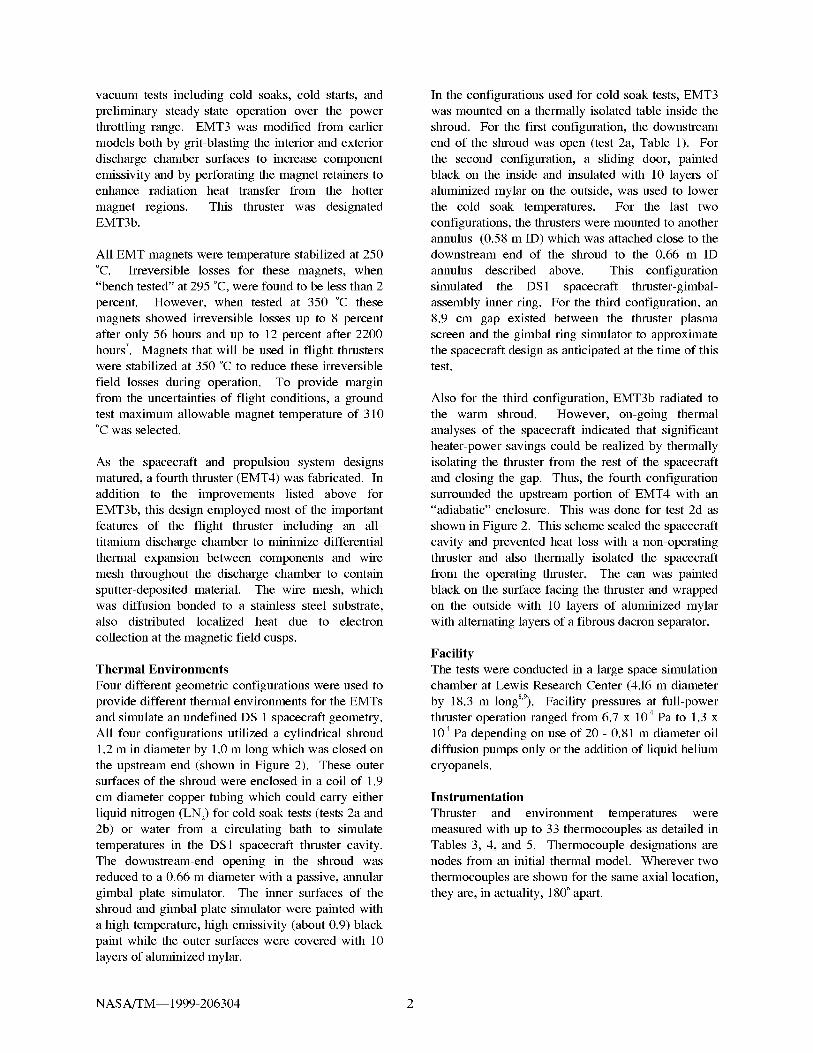
vacuumtestsincludingcold soaks, cold starts, and
preliminary steady-state operation over the power
throttling range. EMT3 was modified from earlier
models both by grit-blasting the interior and exterior
discharge chamber surfaces to increase component
emissivity and by perforating the magnet retainers toenhance radiation heat transfer from the hotter
magnet regions. This thruster was designatedEMT3b.
All EMT magnets were temperature stabilized at 250
°C. Irreversible losses for these magnets, when"bench tested" at 295 °C, were found to be less than 2
percent. However, when tested at 350 °C these
magnets showed irreversible losses up to 8 percent
after only 56 hours and up to 12 percent after 2200
hours 7. Magnets that will be used in flight thrusterswere stabilized at 350 °C to reduce these irreversible
field losses during operation. To provide margin
from the uncertainties of flight conditions, a ground
test maximum allowable magnet temperature of 310°C was selected.
As the spacecraft and propulsion system designs
matured, a fourth thruster (EMT4) was fabricated. In
addition to the improvements listed above for
EMT3b, this design employed most of the important
features of the flight thruster including an all-
titanium discharge chamber to minimize differential
thermal expansion between components and wire
mesh throughout the discharge chamber to contain
sputter-deposited material. The wire mesh, which
was diffusion bonded to a stainless steel substrate,also distributed localized heat due to electron
collection at the magnetic field cusps.
Thermal Environments
Four different geometric configurations were used to
provide different thermal environments for the EMTs
and simulate an undefined DS 1 spacecraft geometry.
All four configurations utilized a cylindrical shroud
1.2 m in diameter by 1.0 m long which was closed on
the upstream end (shown in Figure 2). These outersurfaces of the shroud were enclosed in a coil of 1.9
cm diameter copper tubing which could carry either
liquid nitrogen (LN2) for cold soak tests (tests 2a and
2b) or water from a circulating bath to simulate
temperatures in the DS1 spacecraft thruster cavity.
The downstream-end opening in the shroud was
reduced to a 0.66 m diameter with a passive, annular
gimbal plate simulator. The inner surfaces of the
shroud and gimbal plate simulator were painted with
a high-temperature, high-emissivity (about 0.9) black
paint while the outer surfaces were covered with 10
layers of aluminized mylar.
In the configurations used for cold soak tests, EMT3
was mounted on a thermally isolated table inside the
shroud. For the first configuration, the downstream
end of the shroud was open (test 2a, Table 1). For
the second configuration, a sliding door, painted
black on the inside and insulated with 10 layers of
aluminized mylar on the outside, was used to lower
the cold soak temperatures. For the last two
configurations, the thrusters were mounted to another
annulus (0.58 m ID) which was attached close to thedownstream end of the shroud to the 0.66 m ID
annulus described above. This configuration
simulated the DS 1 spacecraft thruster-gimbal-
assembly inner ring. For the third configuration, an
8.9 cm gap existed between the thruster plasma
screen and the gimbal ring simulator to approximate
the spacecraft design as anticipated at the time of thistest.
Also for the third configuration, EMT3b radiated to
the warm shroud. However, on-going thermal
analyses of the spacecraft indicated that significant
heater-power savings could be realized by thermally
isolating the thruster from the rest of the spacecraft
and closing the gap. Thus, the fourth configuration
surrounded the upstream portion of EMT4 with an"adiabatic" enclosure. This was done for test 2d as
shown in Figure 2. This scheme sealed the spacecraft
cavity and prevented heat loss with a non-operating
thruster and also thermally isolated the spacecraft
from the operating thruster. The can was painted
black on the surface facing the thruster and wrapped
on the outside with 10 layers of aluminized mylar
with alternating layers of a fibrous dacron separator.
Facility
The tests were conducted in a large space simulation
chamber at Lewis Research Center (4.16 m diameter
by 18.3 m longS'9). Facility pressures at full-power
thruster operation ranged from 6.7 x 10⁴ Pa to 1.3 x
104 Pa depending on use of 20 - 0.81 m diameter oil
diffusion pumps only or the addition of liquid helium
cryopanels.
Instrumentation
Thruster and environment temperatures were
measured with up to 33 thermocouples as detailed in
Tables 3, 4, and 5. Thermocouple designations arenodes from an initial thermal model. Wherever two
thermocouples are shown for the same axial location,
they are, in actuality, 180 ° apart.
NAS A/TM-- 1999 -206304 2

Procedure
The first two tests (2a and 2b with EMT3) each
consisted of thruster performance tests, thruster cold
soaks, and thruster starts. In each sequence, thethruster was turned on from cold conditions and then
from warmer thruster conditions after it had been
heated by different methods. Operational steady-
state thruster temperatures were obtained over the
full power throttle range of 0.5 kW to 2.3 kW. The
impact of precluding heat conduction along the
thruster mounting struts was also evaluated. Steady-
state conditions were defined as when all temperature
rates-of-change were less than 3 °C per hour.
For test 2c with EMT3b, the shroud was heated to
approximate the temperatures expected in the actual
spacecraft configuration. Shroud wall temperaturesof 20 °C and 50 °C were maintained for the non-
operating thruster and also for the thruster operating
at full power to evaluate magnet temperature
margins. To avoid unnecessary thruster shutdowns
during unattended overnight operation, the high-
voltage power supplies were typically turned off.
The high voltage was also turned off to examinethruster thermal behavior for future environmental
qualification testing in which flight hardware might
be damaged by deposits of material eroded by the
energetic ion beam. In these cases, the main
discharge propellant flow was reduced to maintain
the same discharge power and allow thruster steady-
state temperatures to be reached. Steady-state high-
voltage-off temperatures were recorded after
extended periods and compared with high-voltage-onvalues.
As mentioned earlier, test 2d with EMT4 was
conducted with the thruster thermally isolated from
the shroud or spacecraft simulator. The shroud was
heated to approximately 50 °C, the maximum
spacecraft cavity temperature expected. The thruster
was then operated at full and reduced power levels,
again to evaluate magnet temperature margins.
Results and Discussion
This section discusses the results of the four thermal
tests listed in Table 1.
Engineering Development Test 2aThe thermal environment for test 2a was
configuration #1 in which the thruster was mounted
inside the cylindrical shroud. EMT3 was tested and
the beginning-of-life performance data were found to
be similar to those of EMT2 (the thruster currently in
operation in the Life Demonstration Test6).
Following these initial performance tests, EMT3 wasthen turned off and allowed to cool. The hollow
cathode discharges were then initiated repeatedly to
obtain average warm-shroud ignition times. Those
times were found to be 8.8 and 12.5 seconds,
respectively for the neutralizer and discharge
cathodes, after heating the cathodes normally and
commanding the respective discharge supplies to turn
on. For 14 ignition attempts of test 2a, the impact of
two cold soak cycles appeared to be negligible.
The thruster was then operated at the lowest power
level of about 0.53 kW to obtain steady-state values,
shown in Table 3, after 4 hours of operation. At this
time, the gimbal support heaters were energized to
prevent heat conduction along the struts. The impact
on thruster temperatures after 3 more hours is shown
in Table 3. Magnet temperatures increased about 10
°C while the temperature of the accelerator grid
stiffening ring increased 14 °C. The thruster and
gimbal support heaters were then turned off and
allowed to cool. The thruster was then operated at a
medium power of 1.44 kW and the steady-state
thruster temperatures, shown in Table 3, wereobtained.
Steady-state temperatures at full thruster power could
not be reached due to a high voltage short that
appeared only after two hours of full-power
operation. Therefore, the high-voltage power
supplies were turned off and the main plenum flow
reduced from 23.2 to 3.6 sccm to give the same
discharge power as with beam extraction. All
temperatures, with the exception of those of the ion
optics, are representative of values expected with
beam extraction. Steady-state temperatures for this
case are shown in Table 3. Excluding the cathode
keepers, the maximum temperature observed, 282 °C,
was for the middle and forward (optics-end) magnets.
To evaluate the impact, if any, of operation at magnet
temperatures at the 310 °C limit, the discharge power
was increased to 336 W to raise the magnet
temperature to 310 °C where it was held for 24 hours.
Later, it was found that operation at a beam current
of 1.1 amp required about 8 percent more discharge
current, at the same discharge voltage than it had
earlier. This increase in discharge power is not
unlike that observed early in the 2000 hour test ofEMT 13and in the Life Demonstration Test of EMT26.
As mentioned earlier, the magnets in all EMTs were
temperature stabilized by the manufacturer at 250 °C.
Perhaps small irreversible changes occurred during
operation of EMT3 at 310 °C. Sovey has shown that
elevating individual EMT magnets to temperatures
NASA/TM--1999-206304 3

greaterthanthestabilizedvalueleadstomeasurablemagneticfieldstrengthdegradation7. Magnetic field
strength measurements, at discharge chamber
surfaces, typically have variations greater than 10
percent which can dominate the subtler performance
changes observed here.
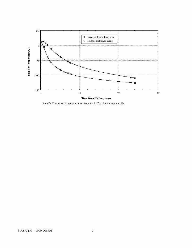
Engineering Development Test 2b
Test configuration #2, with the shroud sliding door,
was used for test 2b. EMT3 was briefly tested over
the power throttle range and overall thruster
performance was essentially unchanged. The
discharge current required at full power was about 10
percent greater than it was for test 2a and it is
postulated that this may be due to magnet
degradation from prior testing. The thruster was then
turned off and allowed to cool to room temperature.
The shroud sliding door was closed and LN 2 was
applied to the shroud cooling lines. Figure 3 shows
that the warmest (forward magnets) and coldest
(neutralizer keeper) thruster temperatures reached
steady-state (less than 3 °C/hour) after about 10
hours. After 24 hours, all thruster temperatures werebetween -109 and -129 ° C as shown in Table 4.
These cold soak temperatures were achieved on 5
occasions for this test segment.
Three attempts were made to preheat the engine after
cold soaks to identify the thermal requirements, if
any, for successful hollow cathode ignition and
thruster power throttling from 0.5 to 2.3 kW. These
thruster heating options will not be required for the
DS 1 mission, but, were examined for future
applications. When 10 or 20 watts (total) of heat
were driven through the mounting struts toward the
thruster, the engine body temperatures increased as
shown in Table 4. A less complex, spacecraft
configuration independent, method of warming the
thruster was to use the discharge cathode heater.
Starting from cold-soak conditions, 50 watts of
discharge cathode heater power was applied for 24
hours which resulted in the thruster temperatureincreases shown in Table 4. Several neutralizer
cathode ignitions were attempted and, as expected, a
trend of increasingly longer neutralizer ignition times
(up to 86 seconds longer than nominal, as determined
in test 2a) was observed as the initial neutralizer
hardware temperature was reduced to the cold-soakvalues.
Thruster startup from cold-soak to ignition to beam
extraction at the minimum power level of 0.53 kW
was uneventful. Steady-state temperatures were
reached after 4 hours. Initial and final (after about 24
hours) temperatures are shown in Table 4. Thruster
starts from cold-soak conditions were repeated
several times to evaluate the ability of the thruster to
quickly throttle to full power. The thruster power
could be increased from 0.5 kW to full power over
three minutes with no adverse consequences.
Because the magnet temperatures, which are of major
concern, are to first order only a function of the
discharge power, additional operation without beam
extraction was investigated. Table 4 gives the
steady-state temperatures for the thruster when
operating at 1.30 kW. Without beam extraction the
xenon neutral density increases and the discharge
voltage drops. To counter this drop and maintain a
constant discharge power, the main flow was reduced
from 12.5 to 3.0 sccm. The resulting temperatures
are shown in Table 4. The thruster parameters were
then increased to give full-power discharge chamberconditions without beam extraction. The main flow
required was only 3.2 sccm compared to 23.2 sccm
with beam extraction. The resulting temperatures are
given in Table 4. The maximum temperature,
excluding the keepers, was 309 °C at the forward
(downstream) magnets. This temperature was higher
than that for the corresponding data of test 2a
because the discharge power here was 320 watts,
14% greater than the 280 watts of test 2a. About half
of this increase was due to the required increase in
discharge current (1.1A) discussed at the end of the
previous section and the rest because the test 2b data
were taken 14 hours (rather than 4 hours) after
conditions were established. Thus, the last column of
temperatures shown in Table 4 were closer to
equilibrium in test 2b than in test 2a.
To evaluate the impact of a configuration in which
heat conduction from a thruster, operating at full
power, to the shroud was not allowed, a test was
performed in which the heaters on the mounting
struts were powered. After 5 hours of strut heater
power adjustments, the thruster was at thermal
equilibrium (less than 0.5 °C per hour change) at the
temperatures shown in Table 4. The difference in
magnet temperatures for this case with and withoutbeam extraction was no more than 3 °C. Note that
the forward magnet temperature increased to 312 ° C,
slightly exceeding the upper-limit criterion.
On-going thruster thermal analyses suggested ways
of removing heat from the thruster magnets. These
included holes in the magnet covers and grit-blasted
surfaces to increase emissivity and enhance radiation
heat transfer. These improvements were
incorporated into EMT3b and EMT4 and evaluated
in subsequent tests.
NAS A/TM-- 1999 -206304 4

EngineeringDevelopmentTest2c
At the time of this test, the DS 1 Project was planning
to mount the thruster (which has a 41 cm OD) to a
58 cm diameter (ID) double-ring gimbal assembly.The thruster was to be recessed in the conic-section
of the spacecraft structure and radiate to the
spacecraft and out through the approximately 9 cm
wide gap. The spacecraft would maintain a cavity
temperature range of 20 to 50 °C. To simulate the DS
1 configuration, a warm water supply replaced the
LN 2 to the shroud for test 2c. Table 5 gives the
steady-state non-operating thruster temperatures
when the shroud temperature was slightly above the
worst case DS 1 temperature (56 °C). Also shown
are the steady-state full-power thruster temperatures
with a 56 °C shroud. Note that the maximum magnet
temperature (forward magnet) for EMT3b and the
warm shroud was only 300 °C even though the
required discharge power at this condition was 340
watts. The lower magnet temperatures, for a warm
shroud and greater discharge power, are believed due
to the thermal design changes built into EMT3b.
Engineering Development Test 2d
EMT4 was fabricated to incorporate most of the
important features found in the flight thruster design 5.
Test 2d was undertaken with insulating surroundings
enclosing the thruster and gimbal ring simulator
annular opening to simulate the latest DS 1 thermal
interface which thermally isolates the thruster from
the spacecraft. This configuration, shown in Figure
2, was based on the needs to minimize spacecraft
heat loss through the annular opening between the
non-operating thruster and the gimbal ring and to
also limit the maximum spacecraft thruster cavity
temperature to 50 °C when the thruster was at full
power. The objectives of these final tests were to
thermally evaluate EMT4 in the isolated enclosure,
validate the thruster thermal models, and quantify
temperature margins for thermally sensitive rare-
earth magnets in the discharge chamber.
Table 5 shows the temperatures of the non-operatingthruster in the 53 °C shroud and resultant 37 °C
adiabatic can. The thruster was throttled from 0.5
kW to 2.3 kW, allowed to reach steady-state with the
high-voltage oft', and then with the high-voltage on.
These full-power thruster temperatures are shown in
Table 5. The maximum magnet temperatures for this
thermally isolated thruster are 288 °C for the aft
magnets and 289 °C for the downstream or forward
magnets, well below the 310 ° C limit set for a 40 ° C
margin from the 350 °C magnet-stabilization
temperature. For the DS 1 mission, operation of the
NSTAR thruster over the power throttle range of 0.5
to 2.3 kW will lead to very conservative magnet
temperatures.
Based on Mirtich's results of tests with a 2.6 kW
mercury ion thruster 1°, thruster temperature increasesof 20 °C and 40 °C at the downstream end of the
anode might be expected for either 2-sun illumination
of the thruster or if the thruster were completly
surrounded by other equal temperature thrusters,
respectively. In these cases, the NSTAR design may
be marginal for very extreme conditions in severe
inbound missions. To further investigate this
condition, tests with a solar simulator are requiredand some additional minor thermal modifications
may be necessary.
Conclusions
The thermal behavior of three NSTAR Engineering
Model Thrusters (EMTs) was evaluated in fourdifferent thermal environments. Each thruster was
instrumented with up to 21 thermocouples. EMT3
was placed in a LN2-cooled shroud which was either
opened or closed at one end. The resulting thruster
temperatures at the end of a typical cold-soak period
ranged from -30 to -84 °C for the open-end case andfrom -109 to -129 °C for the closed-end case. All
thruster startups from cold-soak conditions were
successful with neutralizer hollow cathode ignition
times up to 86 seconds longer than startups from
room temperature. No other adverse effects of
thruster cold-soak and startup to full power were
noted. Thruster performance was unaffected by coldsoaks.
Another concern was the temperature sensitivity of
the rare-earth magnets used to enhance the discharge
chamber ionization efficiency. Flight thruster
magnets were stabilized at 350 °C. A 40 °C margin
from this upper limit was desired. This goal, coupled
with severe spacecraft thermal requirements,
necessitated several changes to the thruster thermal
design. These changes included grit-blasting the
interior and exterior discharge chamber surfaces to
increase component emissivity, perforating the
magnet retainers to enhance radiation heat transfer
from the hotter magnet regions, and using wire mesh
throughout the discharge chamber to distribute
localized heat at the magnetic field cusps. These
modifications were incorporated into EMT4 which
was subsequently tested over the throttle range in a
thermally isolated environment simulating the DS1
spacecraft configuration. Operating at full power in
the adiabatic enclosure, the warmest magnet
temperature observed was only 289 °C. This is well
NAS A/TM-- 1999 -206304 5

belowthemaximumallowabletemperatureof310°C(includingmargin).
During testingit was observedthat magnettemperatureswereprimarilya functionof thedischargepowerandthatif thedischargevoltageandcurrent,experiencedwith beamextraction,weremaintainedwith thehighvoltagepowersuppliesturnedoffbyreducingonlythemainpropellantflow,nearlyall of thethrustersteady-statetemperatureswereunchanged.Thismodeof operationcouldbeusefulfor integrationtestingof ion thrustersonspacecraftwithsputter-deposit-sensitivesurfacesorlenses.
References
1.Burrows, W. E., "The New Millennium," Air and
Space, August/September 1996, pp. 44-53.
2.Patterson, M. J., Haag, T. W., and Hovan, S. A.,
"Performance of the NASA 30 cm Ion Thruster,"
IEPC Paper 93-108, September 1993.
3.Patterson, M. J., et al., "2.3 kW Ion Thruster Wear
Test," AIAA Paper 95-2516, July 1995.
4.Polk, J. E., et al., "A 1000-Hour Wear Test of the
NASA NSTAR Ion Thruster," AIAA Paper 96-2717,
July 1996.
5.Sovey, J. S., et al., "Development of an IonThruster and Power Processor for New Millennium's
Deep Space 1 Mission", AIAA Paper 97-2778, July1997.
6.Polk, J. E., et al., "Engine Operating Characteristics
in a Long Duration Test of the NSTAR Engineering
Model Thruster", proposed IEPC Paper 97-046, Aug.1997.
7.Sovey, J. S., personal communication, August1997.
8.Grisnik, S. P. and Parkes, J. E., "A Large High
Vacuum, High Pumping Speed Space Simulation
Chamber for Electric Propulsion", IEPC Paper 93-
151, Sept. 1993.
9.Pinero, L. R., Patterson, M. J., and Satterwhite, V.
E., "Power Console Development for NASA's
Electric Propulsion Outreach Program", IEPC Paper
93-250 Sept. 1993.
10.Mirtich, M. J., "Thermal-Environment Testing of
a 30-cm Engineering Model Thruster", AIAA Paper
76-1034,Nov. 1976.
Table 1. En_ineerin_
Test Thruster, LN2 cooling HeatedEMT of Shroud ? Struts ?
2a 3 Yes Yes
2b 3 Yes Yes
2c 3b No No
2d 4 No No
(1) In addition to steady-state operating temperatures
9ment Test 2 Descri
End Gimbal RingDoor ? Simulator ?
No No
Yes No
No Yes
No Yes
)tions
"Adiabatic
Can ?
No
No
No
Yes
Primary Test
Ob)ectives(1)
Cold soaks, starts
Cold soaks, starts
Warm cavity
Thermally isolated
Table 2. Evolution of the EMT design (from ref. 5).
Major Features EMTla EMTlb EMTlc EMT2 EMT3 EMT3b EMT4
Major test 2030h 3 1000 h 4 Random 8000h 6 Thermal Thermal Thermalvibration vacuum vacuum vacuum
Main cathode No Yes Mass Yes Yes Yes Yes
keeper electrode? model
Discharge chamber A1/Ti A1/Ti A1/Ti A1/Ti A1/Ti A1/Ti Timaterial
Wire mesh No Partial Partial Partial Partial Partial Yes
throughout ?Gimbal bracket Stainless Stainless A1 Stainless Stainless Stainless Stainless
material steel steel steel steel steel steel
Grit-blast for No No No No No Yes Yes
emissivity control'?
Lightening holes ? No No Yes No No Yes Yes
Flight
Flight
Yes
Ti
Yes
Ti
Yes
Yes
NAS A/TM-- 1999 -206304 6

Thermocouple
designation
207
211
223
203
215
501
307
104
Table 3. Stead"i
Thermocouple
location
middle magnet
disch cham cyl
forward
magnet
cathode cover
aft magnet
cham stiff aft
cathode keeper
accelerator ring
plasma screen
middle
400 neutralizer base
101
102
112
404
GP
S
p.s. upst. end
p.s. middle
p.s. mask opp
neutralizer
neut keeper
gimbal pads
shroud
Case:
Thruster
on?
Table 4. Steady state
Case:
Them]ocouple
designation
207
211
223
203
Thermocouple
location
middle magnet
disch chain cyl
forward magnetcathode cover
aft magnet
chain stiff aft215
219 chain stiff fwd
303
501
307
305
104
optics support
cathode keeper
accelerator ring
accelerator ring
plasnla screen
middle
400 neutralizer base
101
102
112
106
108
404
GP
p.s. upstream
p.s. middle
p.s. mask
oppose neut
p.s. dnstrm near
neut
p.s. dnstrm
oppose neut
neut keeper
gimbal pads
shroud
Tlkruster
on?
cold
soak
No
-38
-34
-32
-39
-39
-36
-30
-84
-49
-76
-82
-31
-54
-96
-139
0.53 i_W
adiabatic
Test 2a (EMT3), °C
1.44 kW 2.30 kW
conditions
No Yes Yes Yes
HV off
191 199 241 268
193 203 248 281
188 198 242 282
195 203 237 262
198 206 245 274
187 197 236 263
439 444 523 564
126 140 162 212
61 89 83 99
166 173 194 197
64 83 86 101
63 94 84 101
84 101 113 140
575 576 539 603
43 111 88 108
30 47 25 29
for
cold 10 W 20 W 50 W' 0.53
soak struts struts cath heat kW
No No No No Yes
109 53 10 62 187
108 52 11 68 189
108 52 11 71 206
109 56 17 154 187
109 54 14 127 189
109 51 9 74 181
109 51 9 169
109 53 10 141
440
108 57 19 23 118
108 57 21 22 119
126 8 +51 60 2
129 88 65 58 152
123 91 61 37 6
117 4 +51 52 9
126 62 27 23 68
118 73 46 33 87
118 60 25 25 59
117 90 71 68 590
122 +73 +98 22 70
187 188 187 187 180
(EMT3), °C
1.30 1.30
kW kW
Yes Yes
HV off
207
224 231
242 247
214 219
222 229
212 218
494 511
167 150
166 149
25 27
140 147
26 29
30 32
98 94
103 104
85 83
552 561
106 106
174 175
2.30 kW 2.30 kW
adiabatic adiabatic
Yes Yes
HV off
271
297 294
309 312
268 266
286 289
277 277
579 598
221 202
217 201
102 104
147 157
68 71
106 108
143 137
136 136
123 120
559 562
204 202
171 171
NAS A/TM-- 1999 -206304 7

Table 5. Steady-State Temperatures for Engineering Development Tests 2c and 2d,°C
Thermocouple
designation205
207
221
223
203
303
Thermocouplelocation
307
110 plasma screen
mask, neut112
GP
middle magnet
middle magnet
Forward magnel
Forward magnel
aft magnet
optics support
accelerator ring
p.s. mask
opp. neut
gimbal padsshroudS
AC adiabatic can
Test 2c (EMT3b) [ Test 2d (EMT4)
Case: warm 2.30kW warm 2.30kW 2.30kW
soak cavity conditionsThruster on? No Yes No Yes Yes
HV off
38 254 34 242 249
38 256 33 246 252
33 300 33 286 289
33 299 32 284 285
39 263 33 282 288
41 218 213 213
36 202 189 177
23 137 31 130 128
31 141 124 121
48 111 38 122 124
56 56 53 49 48
...... 37 120 123
1.81kW 1.81kW
conditions
Yes Yes
HV off
217 219
219 222
256 256
254 252
256 261
189 188
167 154
116 113
108 106
107 108
46 46
105 107
Figure 1. Thruster thermocouple locations
Figure 2. Test fixture
NASA/TM--1999-206304 8
m,
E2
.=
5O
5O
100
150
0 10 20
Time from LN2 on, hours
Figure 3. Cool down temperatures vs time after LN2 on for test segment 2b.
o warmest, forward magnets[] coldest, neutralizer keeper
30
NAS A/TM-- 1999-206304 9

Form ApprovedREPORT DOCUMENTATION PAGEOMB No. 0704-0188
Public reporting burden for this collection of information is estimated to average 1 hour per response, including the time for reviewing instructions, searching existing data sources,
gathering and maintaining the data needed, and completing and reviewing the collection of information. Send comments regarding this burden estimate or any other aspect of this
collection of information, including suggestions for reducing this burden, to Washington Headquarters Services, Directorate for Information Operations and Reports, 1215 Jefferson
Davis Highway, Suite 1204, Arlington, VA 22202-4302, and to the Office of Management and Budget, Paperwork Reduction Project (0704-0188), Washington, DC 20503.
1. AGENCY USE ONLY (Leave blank) 2. REPORT DATE 3. REPORT TYPE AND DATES COVERED
January 1999 Technical Memorandum
4. TITLE AND SUBTITLE
Thermal Environmental Testing of NSTAR Engineering Model Ion Thrusters
6. AUTHOR(S)
Vincent K. Rawlin, Michael J. Patterson, and Raymond A. Becker
7. PERFORMING ORGANIZATION NAME(S) AND ADDRESS(ES)
National Aeronautics and Space Administration
Lewis Research Center
Cleveland, Ohio 44135- 3191
9. SPONSORING/MONITORING AGENCY NAME(S) AND ADDRESS(ES)
National Aeronautics and Space Administration
Washington, DC 20546- 0001
5. FUNDING NUMBERS
WU-242-70-01-00
8. PERFORMING ORGANIZATION
REPORTNUMBER
E-11001
10. SPONSORING/MONITORING
AGENCY REPORT NUMBER
NASA TM--1999-206304
IEPC-97-051
11. SUPPLEMENTARY NOTES
Prepared for the 25th International Electric Propulsion Conference sponsored by the Electric Rocket Propulsion Society,
Cleveland, Ohio, August 24-28, 1997. Vincent K. Rawlin and Michael J. Patterson, NASA Lewis Research Center;
Raymond A. Becker, Jet Propulsion Laboratory, Pasadena, California. Responsible person, Vincent K. Rawlin, organiza-
tion code 5430, (216) 977-7462.
12a. DISTRIBUTION/AVAILABILITY STATEMENT
Unclassified - Unlimited
Subject Categories: 20, 15 and 13 Distribution: Nonstandard
This publication is available from the NASA Center for AeroSpace Information, (301) 6214)390.
12b. DISTRIBUTION CODE
13. ABSTRACT (Maximum 200 words)
NASA's New Millenium program will fly a xenon ion propulsion system on the Deep Space 1 Mission. Tests were
conducted under NASA's Solar Electric Propulsion Technology Applications Readiness (NSTAR) Program with 3
different engineering model ion thrusters to determine thruster thermal characteristics over the NSTAR operating range in
a variety of thermal environments. A liquid nitrogen-cooled shroud was used to cold-soak the thruster to -120 °C. Initial
tests were performed prior to a mature spacecraft design. Those results and the final, severe, requirements mandated by
the spacecraft led to several changes to the basic thermal design. These changes were incorporated into a fmal design and
tested over a wide range of environmental conditions.
14. SUBJECT TERMS
Propulsion; Electric propulsion; Spacecraft propulsion
17. SECURITY CLASSIFICATIONOF REPORT
Unclassified
NSN 7540-01-280-5500
15. NUMBER OF PAGES
1516. PRICE CODE
A0318. SECURITY CLASSIFICATION 19. SECURITY CLASSIFICATION 20. LIMITATION OF ABSTRACT
OF THIS PAGE OF ABSTRACT
Unclassified Unclassified
Standard Form 298 (Rev. 2-89)Prescribed by ANSI Std. Z39-1B298-102