Thermal design methodology for high-heat-flux single … Publication… · · 2010-07-20Projected...
12
598 IEEE TRANSACTIONS ON COMPONENTS AND PACKAGING TECHNOLOGIES, VOL. 26, NO. 3, SEPTEMBER 2003 Thermal Design Methodology for High-Heat-Flux Single-Phase and Two-Phase Micro-Channel Heat Sinks Weilin Qu and Issam Mudawar Abstract—This paper explores several issues important to the thermal design of single-phase and two-phase micro-channel heat sinks. The first part of the paper concerns single-phase heat transfer in rectangular micro-channels. Experimental results are compared with predictions based on both numerical as well as fin analysis models. While the best agreement between predictions and experimental results was achieved with numerical simulation, a few of the fin models are found to provide fairly accurate predictions. The second part of the paper focuses on predicting the incipient boiling heat flux. A comprehensive model based on bubble departure and superheat criteria is developed and validated with experimental data. The incipience model is capable of predicting the location, shape and size of bubbles departing in rectangular micro-channels. In the third part of the study, an analytical model is developed to predict pressure drop across a two-phase micro-channel heat sink. This model provides a detailed assessment of pressure drop concerns with two-phase micro-channels, including compressibility, flashing and choking. Overall, the present study provides important guidelines concerning practical implementation of micro-channel heat sinks in high-heat-flux electronic cooling applications. Index Terms—Boiling, boiling incipience, heat sink, high heat flux, micro-channel, phase change, pressure drop. NOMENCLATURE Area of micro-channel bottom wall, . Area of micro-channel sidewall, . Cross-sectional area of micro-channel, . Effective area for heat transfer along micro-channel wall, . Projected area of bubble, . Planform area of heat sink top surface, . Drag coefficient in (14). Specific heat at constant pressure, . Empirical coefficient in (19). Hydraulic diameter of micro-channel, m. Point half-way from nucleation site to bubble tip. Friction factor. Manuscript received July 17, 2002; revised January 23, 2003. This work was presented at the 8th Intersociety Conference on Thermal and Thermomechan- ical Phenomena in Electronic Systems (ITHERM 2002), San Diego, CA, May 30–June 1, 2002. This work was supported by the Office of Basic Energy Sci- ences, U.S. Department of Energy under Grant DE-FG02-93ER14394-A7. This work was recommended for publication by Associate Editor K. C. Toh upon evaluation of the reviewers’ comments. The authors are with the International Electronic Cooling Alliance (PUIECA), School of Mechanical Engineering, Purdue University, West Lafayette, IN 47907 USA (e-mail: [email protected]). Digital Object Identifier 10.1109/TCAPT.2003.817652 Drag force, . Surface tension force, . Micro-channel mass velocity, . Enthalpy, J/kg. Average convection heat transfer coefficient, . Height of bubble, m. Height of unit cell, m. Height of micro-channel, m. Distance from point to wall or corner, m. Latent heat of vaporization, J/kg. Distance from thermocouple to micro-channel bottom wall, m. Thickness of cover plate, m. Distance from unit cell bottom wall to micro- channel bottom wall, m. Thermal conductivity, . Length of micro-channel, m. , , , Distance between thermocouple holes, m. Two-phase Mach number. Fin parameter, 1/m. Number of micro-channels in heat sink. Micro-channel Nusselt number. Pressure, bar. Length of bubble contact line, m. Micro-channel inlet pressure, bar. Micro-channel outlet pressure, bar. Total power input, W. Prandtl number. Volume flow rate, . Heat flux based on heat sink top planform area, . Incipient boiling heat flux based on heat sink top planform area, . Thermal resistance, . Radius of departing bubble, m. Reynolds number of micro-channel. Bubble Reynolds number. Temperature, . Micro-channel inlet temperature, . Micro-channel outlet temperature, . Saturation temperature, . to Thermocouple readings, . Dimensionless axial velocity. 1521-3331/03$17.00 © 2003 IEEE Authorized licensed use limited to: Purdue University. Downloaded on July 20,2010 at 12:07:17 UTC from IEEE Xplore. Restrictions apply.
-
Upload
hoangkhuong -
Category
Documents
-
view
215 -
download
1
Transcript of Thermal design methodology for high-heat-flux single … Publication… · · 2010-07-20Projected...

598 IEEE TRANSACTIONS ON COMPONENTS AND PACKAGING TECHNOLOGIES, VOL. 26, NO. 3, SEPTEMBER 2003
Thermal Design Methodology for High-Heat-FluxSingle-Phase and Two-Phase
Micro-Channel Heat SinksWeilin Qu and Issam Mudawar
Abstract—This paper explores several issues important tothe thermal design of single-phase and two-phase micro-channelheat sinks. The first part of the paper concerns single-phase heattransfer in rectangular micro-channels. Experimental resultsare compared with predictions based on both numerical aswell as fin analysis models. While the best agreement betweenpredictions and experimental results was achieved with numericalsimulation, a few of the fin models are found to provide fairlyaccurate predictions. The second part of the paper focuses onpredicting the incipient boiling heat flux. A comprehensive modelbased on bubble departure and superheat criteria is developedand validated with experimental data. The incipience model iscapable of predicting the location, shape and size of bubblesdeparting in rectangular micro-channels. In the third part ofthe study, an analytical model is developed to predict pressuredrop across a two-phase micro-channel heat sink. This modelprovides a detailed assessment of pressure drop concerns withtwo-phase micro-channels, including compressibility, flashing andchoking. Overall, the present study provides important guidelinesconcerning practical implementation of micro-channel heat sinksin high-heat-flux electronic cooling applications.
Index Terms—Boiling, boiling incipience, heat sink, high heatflux, micro-channel, phase change, pressure drop.
NOMENCLATURE
Area of micro-channel bottom wall, .Area of micro-channel sidewall, .Cross-sectional area of micro-channel,.Effective area for heat transfer along micro-channelwall, .Projected area of bubble, .Planform area of heat sink top surface,.Drag coefficient in (14).Specific heat at constant pressure, .Empirical coefficient in (19).Hydraulic diameter of micro-channel, m.Point half-way from nucleation site to bubble tip.Friction factor.
Manuscript received July 17, 2002; revised January 23, 2003. This work waspresented at the 8th Intersociety Conference on Thermal and Thermomechan-ical Phenomena in Electronic Systems (ITHERM 2002), San Diego, CA, May30–June 1, 2002. This work was supported by the Office of Basic Energy Sci-ences, U.S. Department of Energy under Grant DE-FG02-93ER14394-A7. Thiswork was recommended for publication by Associate Editor K. C. Toh uponevaluation of the reviewers’ comments.
The authors are with the International Electronic Cooling Alliance(PUIECA), School of Mechanical Engineering, Purdue University, WestLafayette, IN 47907 USA (e-mail: [email protected]).
Digital Object Identifier 10.1109/TCAPT.2003.817652
Drag force, .Surface tension force, .Micro-channel mass velocity, .Enthalpy, J/kg.Average convection heat transfer coefficient,
.Height of bubble, m.Height of unit cell, m.Height of micro-channel, m.Distance from point to wall or corner, m.Latent heat of vaporization, J/kg.Distance from thermocouple to micro-channelbottom wall, m.Thickness of cover plate, m.Distance from unit cell bottom wall to micro-channel bottom wall, m.Thermal conductivity, .Length of micro-channel, m.
, ,,
Distance between thermocouple holes, m.
Two-phase Mach number.Fin parameter, 1/m.Number of micro-channels in heat sink.Micro-channel Nusselt number.Pressure,bar.Length of bubble contact line, m.Micro-channel inlet pressure,bar.Micro-channel outlet pressure,bar.Total power input, W.Prandtl number.Volume flow rate, .Heat flux based on heat sink top planform area,
.Incipient boiling heat flux based on heat sink topplanform area, .Thermal resistance, .Radius of departing bubble, m.Reynolds number of micro-channel.Bubble Reynolds number.Temperature, .Micro-channel inlet temperature, .Micro-channel outlet temperature, .Saturation temperature, .
to Thermocouple readings, .
Dimensionless axial velocity.
1521-3331/03$17.00 © 2003 IEEE
Authorized licensed use limited to: Purdue University. Downloaded on July 20,2010 at 12:07:17 UTC from IEEE Xplore. Restrictions apply.

QU AND MUDAWAR: THERMAL DESIGN METHODOLOGY 599
Axial velocity, m/s.Axial velocity at half-way point , m/s.Micro-channel inlet velocity, m/s.Micro-channel outlet velocity, m/s.Specific volume, .Velocity vector, m/s.Specific volume difference between saturated vaporand saturated liquid, .Width of heat sink top planform area, m.Width of unit cell, m.Width of micro-channel, m.Half-width of wall separating micro-channels, m.Cartesian coordinate.Thermodynamic equilibrium quality.Dimensionless thermal entry distance.Cartesian coordinate.Dimensionless Cartesian coordinate.Cartesian coordinate.Dimensionless Cartesian coordinate.
Greek Symbols:Aspect ratio.Fin efficiency.Dimensionless temperature.Equilibrium contact angle,rad.Advancing contact angle,rad.Receding contact angle,rad.Dynamic viscosity, .Density, .Surface tension, N/m.
Subscripts:Micro-channel bottom wall.
air Air.ave Average.cap Capacity.cond Conduction.
Vapor.Liquid.
fin Fin.in Micro-channel inlet.
Lexan cover.out Micro-channel exit.
Solid (oxygen-free copper).Single-phase.Thermocouple.Two-phase.
I. INTRODUCTION
M ICRO-CHANNEL heat sinks constitute a powerfulmeans for dissipating large amounts of heat from small
surfaces. They possess several unique attributes that makethem prime contenders for the next generation of coolers forhigh performance computer processors and laser diodes. Atypical heat sink contains a large number of small diametercoolant channels. Liquids such as water and fluorochemicalsare two types of coolant that are favored with micro-channelheat sinks. Heat sinks are classified into single-phase or
two-phase according to whether boiling of liquid occurs insidethe micro-channels.
Single-phase micro-channel heat sinks have been studiedquite extensively during the last two decades [1]–[15]. Heatsinks with different substrate materials and dimensions havebeen fabricated and tested with various cooling liquids. Test re-sults have demonstrated several technical merits of single-phasemicro-channel heat sinks, namely, the ability to produce verylarge heat transfer coefficients, small size and volume perheat load, and small coolant inventory requirements [1]–[6].In addition to experimental work, several theoretical studiescan be found in the literature [7]–[15]. One of the primaryobjectives of these studies is to develop heat transfer modelingtools that are essential to the design and optimization of heatsink geometry. Two different approaches have been adopted:the fin analysis method and the numerical method. In the finanalysis method, the solid walls separating micro-channels aremodeled as thin fins. Heat transfer analysis of the heat sinkis greatly simplifies by introducing such approximations asone-dimensional heat transfer along the fins, constant convec-tive heat transfer coefficient, and uniform fluid temperature[7]–[11]. The numerical method, on the other hand, involvesdetailed solution of the governing momentum and energyequations using numerical techniques [12]–[15].
Two-phase micro-channel heat sinks offer the same at-tributes as their single-phase counterparts while providingthe following important added benefits: higher convectiveheat transfer coefficients, better temperature uniformity, andsmaller coolant flow rates. Several aspects of fluid flow andboiling in two-phase micro-channel heat sinks have beeninvestigated, namely, boiling incipience [16], pressure drop[17]–[20], bubble activity and flow patterns [20], [21], heattransfer characteristics [17]–[19], [22], [23], and critical heatflux (CHF) [17], [18]. Most two-phase studies are experimentaland very few are dedicated to modeling.
The aforementioned studies provide valuable insight into theheat transfer characteristics in both single-phase and two-phasemicro-channel heat sinks. However, our understanding remainsquite limited, considering the lack of reliable predictive toolsfor practical heat sink design. In this study, several funda-mental and practical issues important to the thermal design ofmicro-channel heat sink are discussed, and experiments wereperformed to assess the predictive capabilities of differentmodels. These technical issues are linked together by a series ofevents associated with the transition from single-phase liquidcooling to flow boiling. In micro-channel heat sinks, the coolantremains in liquid state under conditions of high liquid flow rateor low heat flux. In the first part of this paper, single-phaseexperimental results are compared with predictions based onboth the numerical method and several previous fin analysismethods. Decreasing liquid flow rate or increasing input heatflux will eventually lead to incipient boiling in micro-channelswith the formation of a few vapor bubbles near the channelexit. Incipient boiling is an important parameter in heat sinkdesign since it constitutes the upper design limit for heat sinksthat are intended for single-phase liquid cooling only, and alower limit for two-phase heat sinks indented for maximumheat dissipation. The second part of this study concerns both
Authorized licensed use limited to: Purdue University. Downloaded on July 20,2010 at 12:07:17 UTC from IEEE Xplore. Restrictions apply.

600 IEEE TRANSACTIONS ON COMPONENTS AND PACKAGING TECHNOLOGIES, VOL. 26, NO. 3, SEPTEMBER 2003
Fig. 1. Flow loop.
measurement and prediction of incipient boiling heat flux ina micro-channel heat sink. With a further decrease in liquidflow rate or increase in heat flux, flow boiling becomes moreprevalent as a liquid-vapor mixture occupies a significantportion of the channel length. In the third part of this paper,an analytical model is presented to determine pressure dropfor water flow boiling in a micro-channel heat sink, includingcompressibility, flashing, and choking effects.
II. M ICRO-CHANNEL HEAT SINK FACILITY
A. Flow Loop
Fig. 1 shows the flow loop that was constructed to conditionthe working fluid, deionized water, to the desired micro-channelheat sink flow rate, inlet temperature, and outlet pressure. Thewater was pumped through the loop via a magnetically coupledgear pump. Only a portion of the pumped fluid entered the heatsink; the balance was bypassed. Upstream of the test modulecontaining the heat sink were a filter, an inline heater, two par-allel rotameters, and a constant temperature bath. The inlineheater and constant temperature bath brought the water to thedesired test module inlet temperature. Outlet pressure controlwas achieved by a throttling valve located downstream from thetest module, which was followed by a heat exchanger to con-dense any vapor exiting the test module before the water re-turned to the reservoir.
B. Test Module
Fig. 2 illustrates the construction of the test module, whichconsisted of a micro-channel heat sink, housing, cover plate,and twelve cartridge heaters. The micro-channel heat sink wasfabricated from a single block of oxygen-free copper. The plan-form (top) surface of the heat sink was 1.0 cm wide and 4.48 cmlong. Twenty-one equidistantly spaced rectangular micro-slots,231 in width and 712 in depth, were machined withinthe 1-cm width of the top surface. Four Type-K thermocoupleswere inserted below the heat sink top surface to measure theaxial temperature distribution inside the heat sink. Twelve holeswere drilled into the bottom of the heat sink to accommodatethe cartridge heaters. These cartridge heaters were powered bya single 0–110VAC variac, and their total power dissipationwas measured by a precision wattmeter. Three thin slots werecut from the bottom surface up through most of the heat sink’sheight to reduce longitudinal heat spread within the heat sink.
Fig. 2. Test module construction.
The heat sink housing was made from G-7 fiberglass plastic.The central part of the housing was removed where the heatsink was inserted. A small protruding platform machined aroundthe periphery of the heat sink ensured the top surface of theheat sink was flush with the top surface of the housing. Thehousing contained plenums both upstream and downstream ofthe micro-channels as shown in Fig. 2. Two absolute pressuretransducers were connected to the plenums to measure the inletand exit pressures. Also located in the plenums were two Type-Kthermocouples to measure the inlet and exit temperatures.
A cover plate made from transparent polycarbonate plastic(Lexan) was bolted atop the housing. The cover plate and micro-slots in the heat sink top surface formed closed micro-channels.A microscope was positioned above the cover plate to observebubble activity inside the micro-channels as shown in Fig. 1.
C. Measurement Uncertainty
Measurement uncertainties associated with the wattmeter, ro-tameters, and pressure transducers were less than 0.5, 4, and3.5%, respectively. The uncertainty associated with the thermo-couple measurements was smaller than 0.3. Heat loss to theambient was estimated at less than 1% of the total power input;the cartridge heater power measured by the wattmeter was there-fore used for all heat flux calculations.
Authorized licensed use limited to: Purdue University. Downloaded on July 20,2010 at 12:07:17 UTC from IEEE Xplore. Restrictions apply.

QU AND MUDAWAR: THERMAL DESIGN METHODOLOGY 601
TABLE IOPERATING CONDITIONS FORSINGLE-PHASE TESTS
III. H EAT TRANSFERCHARACTERISTICS OFSINGLE-PHASE
MICRO-CHANNEL HEAT SINK
A. Experimental Procedure
The operating conditions for the single-phase heat transferexperiments are given in Table I, where inlet velocity,, andeffective heat flux, , were determined from
(1)
(2)
During each test, the flow loop components were first adjustedto yield the desired operating conditions. The heat sink wasthen allowed to reach steady-state, following which the inlet andoutlet pressures, and , outlet temperature, , heatsink temperatures, to , and heater power, , weremeasured.
B. Numerical Method
Taking advantage of symmetry, a micro-channel heat sinkunit cell containing a single micro-channel and surroundingsolid is chosen as shown in Fig. 3. Dimensions of the unit cellare given in Table II.
Heat transfer in the unit cell is a conjugate one combiningheat conduction in the solid and convection to the cooling fluid.To simplify the analysis, the following approximations were em-ployed: steady-state laminar flow, constant solid and fluid prop-erties, and negligible natural air convection in the deep slots inthe underside of the heat sink. The resulting governing differen-tial equations can be written as follows. For the cooling water
(3)
(4)
(5)
For the solid regions
(6)
(7a)
(7b)
(7c)
A uniform velocity and a fully-developed flow are applied at thechannel inlet and exit, respectively. Zero velocity is assigned toall other solid boundaries. For thermal boundary conditions, aconstant heat flux and constant natural convection coefficientare applied at the unit cell bottom wall (Wall) and at the unitcell top wall (Wall ), respectively. Adiabatic boundary con-ditions are applied to all other boundaries of the solid region.For the liquid region, a constant temperature is applied at the
Fig. 3. Micro-channel heat sink unit cell.
TABLE IIDIMENSIONS OFMICRO-CHANNEL HEAT SINK UNIT CELL
Fig. 4. Schematic of temperature profiles in heat sink unit cell.
channel inlet, and the flow is assumed thermally fully devel-oped at the outlet.
A numerical scheme utilizing the SIMPLE algorithm [24]was developed to solve (3)–(7c) to obtain the temperature field
Authorized licensed use limited to: Purdue University. Downloaded on July 20,2010 at 12:07:17 UTC from IEEE Xplore. Restrictions apply.

602 IEEE TRANSACTIONS ON COMPONENTS AND PACKAGING TECHNOLOGIES, VOL. 26, NO. 3, SEPTEMBER 2003
TABLE IIISUMMARY OF FIN ANALYSIS MODELS
within the heat sink unit cell. Details concerning the numericaltechniques used when applying the SIMPLE algorithm to a con-jugate heat transfer problem are available elsewhere [6], [15],[24], [25].
C. Fin Analysis Method
The fin analysis method is a simplified approach to evaluatingthe temperature field within the heat sink unit cell. The tech-nique for determining the temperature at the heat sink’s ther-mocouple plane (see Fig. 3) using the fin analysis method is asfollows.
After introducing the approximations discussed in Section I,the longitudinal profiles for water bulk temperature, channelbottom wall (Wall ) temperature, and thermocouple plane tem-perature can be determined as shown in Fig. 4. For a given,
the thermocouple plane temperature at a longitudinal distancecan be evaluated from
(8)
, , and are called the capacity resistance, finresistance, and conduction resistance, respectively, and can becalculated from
(9)
(10)
(11)
Equations (9)–(11) are adopted in most fin analysis models,though a variety of relations have been proposed for and
when evaluating . A summary of these relations is
Authorized licensed use limited to: Purdue University. Downloaded on July 20,2010 at 12:07:17 UTC from IEEE Xplore. Restrictions apply.
QU AND MUDAWAR: THERMAL DESIGN METHODOLOGY 603
(a)
(b)
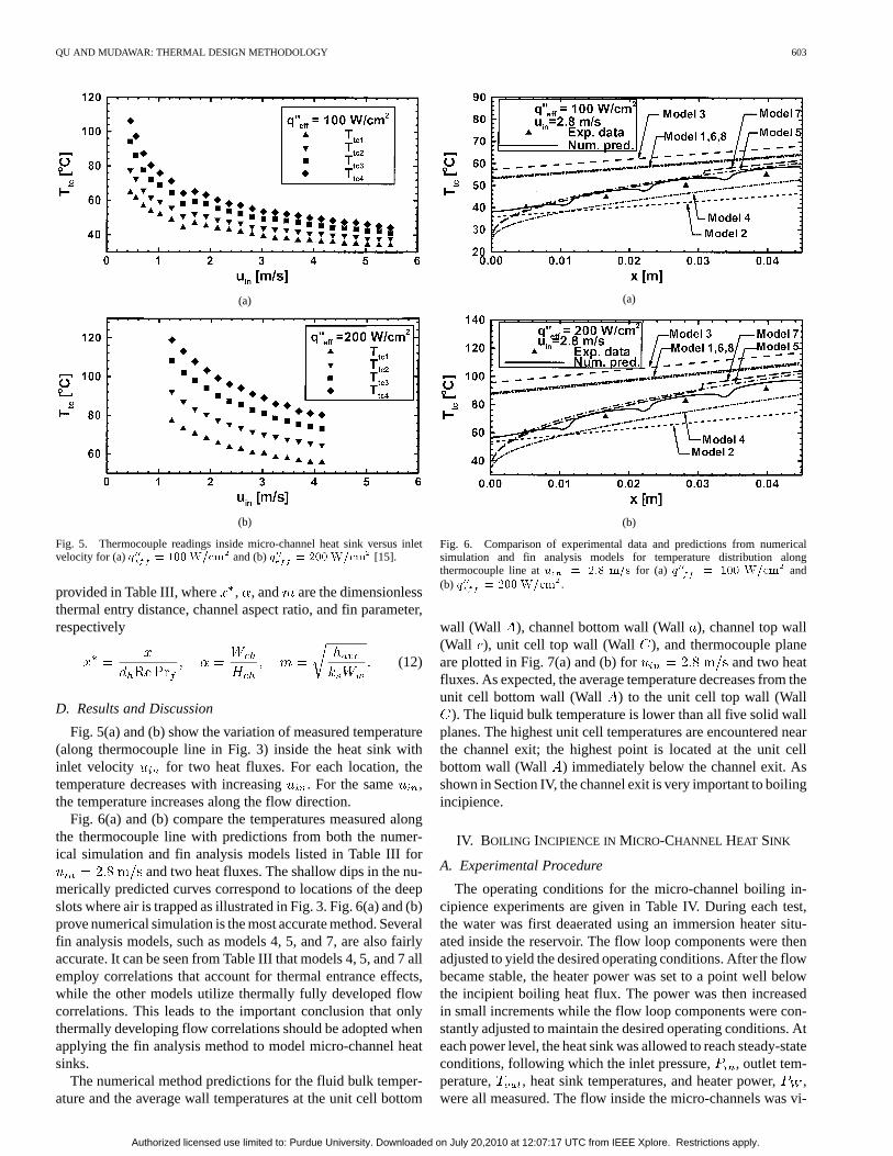
Fig. 5. Thermocouple readings inside micro-channel heat sink versus inletvelocity for (a)q = 100W=cm and (b)q = 200W=cm [15].
provided in Table III, where , , and are the dimensionlessthermal entry distance, channel aspect ratio, and fin parameter,respectively
(12)
D. Results and Discussion
Fig. 5(a) and (b) show the variation of measured temperature(along thermocouple line in Fig. 3) inside the heat sink withinlet velocity for two heat fluxes. For each location, thetemperature decreases with increasing. For the same ,the temperature increases along the flow direction.
Fig. 6(a) and (b) compare the temperatures measured alongthe thermocouple line with predictions from both the numer-ical simulation and fin analysis models listed in Table III for
and two heat fluxes. The shallow dips in the nu-merically predicted curves correspond to locations of the deepslots where air is trapped as illustrated in Fig. 3. Fig. 6(a) and (b)prove numerical simulation is the most accurate method. Severalfin analysis models, such as models 4, 5, and 7, are also fairlyaccurate. It can be seen from Table III that models 4, 5, and 7 allemploy correlations that account for thermal entrance effects,while the other models utilize thermally fully developed flowcorrelations. This leads to the important conclusion that onlythermally developing flow correlations should be adopted whenapplying the fin analysis method to model micro-channel heatsinks.
The numerical method predictions for the fluid bulk temper-ature and the average wall temperatures at the unit cell bottom
(a)
(b)
Fig. 6. Comparison of experimental data and predictions from numericalsimulation and fin analysis models for temperature distribution alongthermocouple line atu = 2:8 m=s for (a) q = 100 W=cm and(b) q = 200 W=cm .
wall (Wall ), channel bottom wall (Wall ), channel top wall(Wall ), unit cell top wall (Wall ), and thermocouple planeare plotted in Fig. 7(a) and (b) for and two heatfluxes. As expected, the average temperature decreases from theunit cell bottom wall (Wall ) to the unit cell top wall (Wall
). The liquid bulk temperature is lower than all five solid wallplanes. The highest unit cell temperatures are encountered nearthe channel exit; the highest point is located at the unit cellbottom wall (Wall ) immediately below the channel exit. Asshown in Section IV, the channel exit is very important to boilingincipience.
IV. BOILING INCIPIENCE INMICRO-CHANNEL HEAT SINK
A. Experimental Procedure
The operating conditions for the micro-channel boiling in-cipience experiments are given in Table IV. During each test,the water was first deaerated using an immersion heater situ-ated inside the reservoir. The flow loop components were thenadjusted to yield the desired operating conditions. After the flowbecame stable, the heater power was set to a point well belowthe incipient boiling heat flux. The power was then increasedin small increments while the flow loop components were con-stantly adjusted to maintain the desired operating conditions. Ateach power level, the heat sink was allowed to reach steady-stateconditions, following which the inlet pressure, , outlet tem-perature, , heat sink temperatures, and heater power,,were all measured. The flow inside the micro-channels was vi-
Authorized licensed use limited to: Purdue University. Downloaded on July 20,2010 at 12:07:17 UTC from IEEE Xplore. Restrictions apply.

604 IEEE TRANSACTIONS ON COMPONENTS AND PACKAGING TECHNOLOGIES, VOL. 26, NO. 3, SEPTEMBER 2003
(a)
(b)
Fig. 7. Numerical predictions of average temperature foru = 2:8 m=s:(a) q = 100W=cm and (b)q = 200W=cm [15].
TABLE IVOPERATING CONDITIONS FORBOILING INCIPIENCETESTS
sually monitored with the aid of the microscope. The effec-tive heat flux measured when the first bubbles appeared insidethe micro-channels was defined as the incipient boiling heatflux, . At boiling incipience, a small number of nucleationsites appeared simultaneously close to the exit of several (typi-cally five to eight) micro-channels; one or two sites were typi-cally activated per micro-channel. After nucleation, bubbles firstgrew to detachment size before being entrained into the liquidflow and deposited into the downstream plenum, where theycollapsed.
B. Mechanistic Model of Incipient Boiling Heat Flux
A new mechanistic model based on bubble departure criteriais developed to predict the incipient boiling heat flux, . Themodel development is based on the following two assumptions:
1) bubble departure will occur when the liquid drag force ex-erted on the bubble overcomes the surface tension force;
2) a bubble will only grow and detach if the lowest temper-ature point along its interface is at least equal to the satu-ration temperature.
(a)
(b)
Fig. 8. Appearance of departing bubble (a) at channel cross section and(b) along flow direction.
The observed bubble activities revealed boiling incipiencestrongly depends on both the hydrodynamic and thermal con-ditions at the micro-channel exit. A two-dimensional analysis istherefore performed on the exit of the unit cell shown in Fig. 3to obtain both the velocity and temperature distributions in theliquid.
1) Mechanical Considerations:According to the firstassumption of the incipience model, the forces acting on adeparting bubble should be in balance. In this model, theassumptions about bubble shape and forces of Al-Hayes andWinterton [26] are adopted and modified to account for thecomplexities of bubble growth in a rectangular micro-channel.Vapor bubbles are grouped into bottom wall bubbles, side-wall bubbles, and corner bubbles. The bubbles are treated astruncated spheres with contact angles at the wall equal to theequilibrium contact angle as illustrated in Fig. 8(a). At thepoint of bubble departure, the liquid drag force and surfacetension forces must balance each other
(13)
The drag force, , is assumed to be proportional to the pro-jected area of the bubble facing the flow and the dynamic pres-sure of the cooling water, and can be evaluated from [26]
(14)
Authorized licensed use limited to: Purdue University. Downloaded on July 20,2010 at 12:07:17 UTC from IEEE Xplore. Restrictions apply.

QU AND MUDAWAR: THERMAL DESIGN METHODOLOGY 605
where , and are the drag coefficient, projected area ofthe bubble, and velocity at a pointhalf-way from the nucle-ation site to the bubble tip, respectively. For bottom wall andsidewall bubbles
(15)
and for corner bubbles
(16a)
(16b)
The drag coefficient is a function of the bubble Reynoldsnumber [26]
(17a)
(17b)
where is employed as the characteristic velocity when eval-uating
(18)
The surface tension force is evaluated as
(19)
where , and are the length of the contact line, recedingcontact angle and advancing contact angle, respectively.in(19) is an empirical coefficient given by [26]
(20)
where is in degrees. For bottom wall and sidewall bubbles
(21)
and for corner bubbles
(22a)
(22b)
and are modified contact angles at the bubble upstreamand downstream stagnation points, respectively, as illustrated inFig. 8(b), which can be calculated from the following correla-tions proposed by Winterton [27] for water
(23a)
(23b)
Substituting (14) and (19) into (13) and rearranging termsyield, for bottom wall and sidewall bubbles
(24)
and for corner bubbles
(25a)
(25b)
The detailed liquid velocity distribution at the micro-channelexit is required to evaluate . Fully-developed single-phaselaminar flow in a rectangular duct is assumed [28] just upstreamof the bubble. Given the velocity field, nucleation site position,and all relevant material properties, the radius of a departingbubble, , can be calculated by solving (24), (25a) or (25b).Once is known, the geometry of the bubble can be easilyspecified.
2) Thermal Considerations:According to the secondassumption of the incipience model, the entire bubble interfacemust be superheated before a bubble can depart. To meet thisrequirement, the lowest temperature along the bubble’s inter-face should be greater than, or at least equal to the saturationtemperature. The temperature distribution around the bubbleinterface should therefore be determined to identify the lowesttemperature point along the interface. This can be accomplishedonce both the geometry of the departing bubble and the liquidtemperature distribution at the channel exit are determined.
The temperature distribution in the liquid can be determinedby solving a two-dimensional conjugate heat transfer problemat the exit of the heat sink unit cell. The following dimensionlessparameters are introduced:
(26)
Assuming fully-developed single-phase laminar flow, the en-ergy equation, (5), corresponding to the different regions of theexit unit cell can be nondimensionalized as
(27)
(28)
(29)
The boundary condition for Wall A of the unit cell is
(30)
and all other unit cell boundaries are assumed adiabatic.A numerical scheme utilizing the finite difference method
was developed to solve (27)–(29) to calculate the dimensionless
Authorized licensed use limited to: Purdue University. Downloaded on July 20,2010 at 12:07:17 UTC from IEEE Xplore. Restrictions apply.

606 IEEE TRANSACTIONS ON COMPONENTS AND PACKAGING TECHNOLOGIES, VOL. 26, NO. 3, SEPTEMBER 2003
Fig. 9. Comparison of experimental results and model predictions for incipientboiling heat flux [16].
temperature field. Detailes concerning the numerical techniquesemployed in this model are available elsewhere [16], [24], [25].
3) Procedure to Predict the Incipient Boiling Heat Flux:First, the force balance calculations are performed. is setto be equal to the inlet velocity due to the small liquiddensity variations along the micro-channel. The velocity fieldat the micro-channel exit is then computed using a formulaprovided in [28]. The bubble departure radius,, is calculatedfor a large number of nucleate sites equidistantly spaced alongthe micro-channel wall by solving (24), (25a), or (25b).
Next, the thermal analysis is performed. The dimensionlesstemperature field, , at the heat sink unit cell exit is determinedby solving (27)–(29) numerically. A small value is then assignedto , and the mean exit temperature, , is determined froma simple energy balance
(31)
The liquid temperature, , field, is determined by substitutingand into the dimensionless temperature,, field.
Given the bubble departure radius and temperature field atchannel exit, the lowest temperature along the bubble interfaceis calculated for each nucleation site along the micro-channelwall.
The value of heat flux, , is then increased and thermalanalysis repeated until the lowest temperature along the inter-face of a bubble just exceeds the saturation temperature. The
value for this condition is the incipient boiling heat flux,, for the micro-channel heat sink.
C. Model Predictions
Fig. 9 shows the measured incipient boiling heat flux, ,increases with increasing inlet velocity, , and decreasinginlet temperature, . Also shown in Fig. 9 are the predictionsbased on the present model. Two different equilibrium contactangles are assumed, 30 and 80, due to the variability ofcontact angle of water on metallic surfaces. Good agreement isshown between the predictions for both angles and the incipientboiling heat flux data, proving the effectiveness of this newmodel for thermal design of two-phase micro-channel heatsinks. The model is not valid below a minimum , which isa function of , for which bubbles approach the size of themicro-channel cross section. Details concerning this limit canbe found in [16].
Fig. 10. Schematic of flow regions in a micro-channel.
V. PRESSUREDROP IN TWO-PHASE MICRO-CHANNEL
HEAT SINK
A. Pressure Drop Model
As shown in Fig. 10, water is supplied into the heat sink sub-cooled . Heat is transferred from the solid heatsink to the water, which results in a stream-wise increase inthe water temperature. Eventually, boiling is initiated inside themicro-channels. The flow from this point to the heat sink exitconsists of a two-phase vapor-liquid mixture. For conveniencein predicting the pressure drop, the total length of the heat sink,
, is divided into two sections based upon the range of ther-modynamic equilibrium quality, . From the subcooled inlet
to the location of is the single-phase length,. The downstream section begins with zero quality and con-
tinues to the heat sink exit , and is referred to asthe two-phase length, . The total pressure drop across themicro-channel heat sink includes the pressure drops from thesingle-phase and two-phase regions
(32)
The two-phase region is characterized by saturated boiling,which is described using the homogeneous equilibrium model.This model is based on the assumption that liquid and vaporphases form a homogeneous mixture with equal and uniformvelocities, and properties are uniform within each phase. Ap-plying conservation of mass, energy, and momentum to the dif-ferential control volume shown in Fig. 10 and rearranging termsyield the following equations [19], [29], respectively, where allliquid and vapor properties are functions of local pressure only,as seen in (33) and (34) shown at the bottom of the next page.The numerator in (34) is the sum of the frictional and accelera-tional components, the latter is the result of heating alone. Thedenominator of (34) can be expressed as , where isthe two-phase Mach number
(35)
Authorized licensed use limited to: Purdue University. Downloaded on July 20,2010 at 12:07:17 UTC from IEEE Xplore. Restrictions apply.

QU AND MUDAWAR: THERMAL DESIGN METHODOLOGY 607
This Mach number expression is the sum of the following terms,from left to right, respectively, for kinetic energy changes, com-pressibility, and flashing.
Pressure drop across the two-phase region, , can be cal-culated by solving the coupled (33) and (34) simultaneously.The fourth-order Runge-Kutta technique is employed to solvethese equations.
Two distinct approaches are generally employed to deter-mine the two-phase friction factor . In the first approach,
is evaluated using standard single-phase friction factorcorrelations with the viscosity term replaced by a two-phasemixture viscosity [29]. Different relationships have beenproposed for the two-phase viscosity as a function of individualphase viscosities and vapor quality. The degree of success ofthese relationships depends upon both channel geometry andtest conditions. Alternatively, can be estimated directlyfrom measured two-phase pressure drop; a value in the rangeof 0.0029 to 0.0033 was suggested for low pressure flashingsteam-water flow [29]. A recent study by Bowers and Mudawar[19] indicated a value of provides excellent agree-ment between predictions of the homogeneous equilibriummodel and their pressure drop data for R-113 flow boiling in aheat sink with circular micro-channels. The value of 0.003 istherefore assumed for in the present study as well.
For the single-phase region of the channel, a fully developedflow is assumed. This may underestimate the single-phase pres-sure drop by neglecting the developing flow pressure drop aswell as the inlet and exit pressure losses. However, the pressuredrop within the single-phase region is much smaller than thetwo-phase region (as will be discussed later), and the error in-troduced is small. Therefore, the pressure drop across the single-phase region can be evaluated from
(36)
where an appropriate single-phase friction factorfor laminarflow in a rectangular channel with smooth walls is employed[28].
B. Results and Discussion
A test case is analyzed here to help illustrate the variousparametric influences for two-phase micro-channel heat sinks.Water is used as the cooling fluid and an inlet velocity of0.34 m/s, inlet pressure of 1.5 bar, and effective heat flux of200 are assumed.
Fig. 11(a) shows the predicted pressure distribution along thetwo-phase micro-channel. The pressure changes are small in the
(a)
(b)
Fig. 11. (a) Pressure drop distribution along micro-channel. (b) Two-phaseMach number distribution along micro-channel.
single-phase region and increase considerably in the two-phaseregion. Further analysis indicates that the larger pressure dropwithin the two-phase region is due mostly to the accelerationaleffect represented by the second term in the numerator of (35).This accelerational effect is the result of a significant increasein flow velocity in the two-phase region caused by the reductionin average density that accompanies the vapor production.
The property variations with pressure also contribute to pres-sure loss within the two-phase region, which accounts for thenonlinear behavior of the pressure gradient. The axial distribu-tion of two-phase Mach number is presented in Fig. 11(b). TheMach number increases monotonically along the flow direction.Fig. 11(b) also shows the individual contributions of kinetic en-ergy changes, compressibility, and flashing to the Mach number.For the conditions studied, compressibility plays the most dom-inant role.
Fig. 12 shows the variation of pressure drop across the heatsink with inlet velocity. Pressure starts increasing with in-creasing velocity for small inlet velocities, then decreases, and
(33)
(34)
Authorized licensed use limited to: Purdue University. Downloaded on July 20,2010 at 12:07:17 UTC from IEEE Xplore. Restrictions apply.

608 IEEE TRANSACTIONS ON COMPONENTS AND PACKAGING TECHNOLOGIES, VOL. 26, NO. 3, SEPTEMBER 2003
Fig. 12. Effects of water inlet velocity and effective heat flux on pressure drop.
eventually increases again. As discussed earlier, pressure dropin the two-phase region is much higher than in the single-phaseregion. With a very small inlet velocity, two-phase flow willprevail over a greater portion of the micro-channel length.The significant vapor production causes large accelerationalpressure losses that are responsible for the initial increasein pressure drop. However, with increasing inlet velocity,the single-phase length begins increasing, and the pressuredrop lowering effect of the single-phase region becomes evenmore dominant. When inlet velocity becomes large, the flowinside the micro-channels is comprised of single-phase liquid,where pressure drop increases rather mildly with increasinginlet velocity. Fig. 12 also shows the pressure drop increasessignificantly in the two-phase region with increasing effectiveheat flux.
The above results prove this model is a simple tool forthermal design of two-phase micro-channel heat sinks. Moreimportantly, it is quite effective at predicting the unique featuresof two-phase pressure drop such as flashing, compressibility,and choking, which few other more complicated modelsare capable of tackling. The model has been successful atpredicting flow boiling pressure drop of R-113 in a heat sinkcontaining 510 circular micro-channels [17], [19]. Onthe other hand, a recent study by Mukherjee and Mudawar[30] revealed several fundamental differences in flow boilingbehavior in micro-channels between water and FC-72; the latteris a fluorochemical coolant with thermophysical propertiesfairly similar to those of R-113. Their results reveal the lowsurface tension and small contact angle of fluorochemicalsproduce bubble departure diameters that are one to two ordersof magnitude smaller than those for water. These new findingspoint to a need to further explore the validity of the homoge-neous equilibrium model with a systematic database for waterflow boiling in micro-channels. Such experiments are the focusof several ongoing studies at PUIECA. A more comprehensiveassessment of the predictive capabilities of different pressuredrop models, including the homogeneous equilibrium model,is available in a separate paper by the authors [31].
VI. CONCLUSION
In this study, several fundamental and practical aspects ofsingle-phase and two-phase micro-channel heat sinks are ad-dressed. Key findings are as follows.
1) The heat transfer characteristics of a single-phase micro-channel heat sink were investigated both experimentallyand theoretically. A comparison between experimental re-sults and predictions based on both numerical simulationand fin analysis models was presented. It is shown that,while numerical simulation offers the most accurate pre-dictions, a few of the simple fin analysis models also pro-vide fairly accurate results. All the successful fin modelsemploy heat transfer correlations that account for thermalentrance effects, while the less successful ones utilizethermally fully developed flow correlations.
2) The incipient boiling heat flux increases with increasinginlet velocity and decreasing inlet temperature. A mech-anistic model was constructed to predict the incipientboiling heat flux. The model is based on a bubble de-parture criterion, which accounts for both force balanceon a bubble and superheat requirement for entire bubbleinterface. This model is capable of predicting the size ofbubbles departing from both the flat surfaces and cornerregions of a rectangular micro-channel, the temperaturefield around the bubble interface, and the location of thefirst bubble to depart. The model predictions are in goodagreement with the incipient boiling heat flux data.
3) An analytical model is developed to predict pressure dropacross a two-phase micro-channel heat sink. The homo-geneous equilibrium model is applied to the two-phaseregion, while fully developed flow is assumed in thesingle-phase region. The pressure changes are small inthe single-phase region and increase considerably inthe two-phase region. The large pressure drop withinthe two-phase region is due mostly to two-phase ac-celeration. Property variations with pressure result in anonlinear variation of pressure gradient in the two-phaseregion, and may result in two-phase choking.
REFERENCES
[1] D. B. Tuckerman and R. F. W. Pease, “High-performance heat sinkingfor VLSI,” IEEE Electron. Devices Lett., vol. EDL-2, pp. 126–129, May1981.
[2] T. Kishimito and T. Ohsaki, “VLSI packaging technique using liquid-cooled channels,”IEEE Trans. Comp., Hybrids, Manufact. Technol., vol.CHMT-9, pp. 328–335, Dec. 1986.
[3] D. Copeland, H. Takahira, W. Nakayama, and B. C. Pak, “Manifold mi-crochannel heat sinks: Theory and experiment,” inAdvances ElectronicPackaging. New York: ASME, 1995, vol. EEP-10, pp. 829–835.
[4] K. Kawano, K. Minakami, H. Iwasaki, and M. Ishizuka, “Micro channelheat exchanger for cooling electrical equipment,” inProc. ASME HeatTransfer Div., vol. HTD-361-3/PID-3, 1998, pp. 173–180.
[5] T. M. Harms, M. J. Kazmierczak, and F. M. Cerner, “Developing convec-tive heat transfer in deep rectangular microchannels,”Int. J. Heat FluidFlow, vol. 20, no. 2, pp. 149–157, Apr. 1999.
[6] W. Qu and I. Mudawar, “Experimental and numerical study of pressuredrop and heat transfer in a single-phase micro-channel heat sink,”Int. J.Heat Mass Transfer, vol. 45, no. 12, pp. 2549–2565, June 2002.
[7] R. J. Phillips, “Micro-channel heat sinks,” inAdvances in Thermal Mod-eling of Electronic Components. New York: ASME Press, 1990, vol.2, pp. 109–184.
[8] R. W. Knight, D. J. Hall, J. S. Goodling, and R. C. Jaeger, “Heat sinkoptimization with application to microchannels,”IEEE Trans. Comp.,Hybrids, Manufact. Technol., vol. 15, pp. 832–842, Oct. 1992.
[9] S. F. Choquette, M. Faghri, M. Charmchi, and Y. Asako, “Optimum de-sign of microchannel heat sinks,” inMicro-Electro-Mechanical Systems(MEMS). New York: ASME, 1996, vol. DSC-59, pp. 115–126.
[10] H. H. Bau, “Optimization of conduits’ shape in micro heat exchangers,”Int. J. Heat Mass Transfer, vol. 41, no. 18, pp. 2717–2723, Sep. 1998.
Authorized licensed use limited to: Purdue University. Downloaded on July 20,2010 at 12:07:17 UTC from IEEE Xplore. Restrictions apply.

QU AND MUDAWAR: THERMAL DESIGN METHODOLOGY 609
[11] D. Y. Lee and K. Vafai, “Comparative analysis of jet impingement andmicrochannel cooling for high heat flux applications,”Int. J. Heat MassTransfer, vol. 42, no. 9, pp. 1555–1568, May 1999.
[12] A. Weisberg, H. H. Bau, and J. N. Zemel, “Analysis of microchannelsfor integrated cooling,”Int. J. Heat Mass Transfer, vol. 35, no. 10, pp.2465–2474, Oct. 1992.
[13] X. Yin and H. H. Bau, “Uniform channel micro heat exchangers,”J.Electron. Packag., vol. 119, no. 2, pp. 89–93, June 1997.
[14] A. G. Fedorov and R. Viskanta, “Three-dimensional conjugate heattransfer in the microchannel heat sink for electronic packaging,”Int. J.Heat Mass Transfer, vol. 43, no. 3, pp. 399–415, Feb. 2000.
[15] W. Qu and I. Mudawar, “Analysis of three-dimensional heat transfer inmicro-channel heat sinks,”Int. J. Heat Mass Transfer, vol. 45, no. 19,pp. 3973–3985, Sept. 2002.
[16] , “Prediction and measurement of incipient boiling heat flux inmicro-channel heat sinks,”Int. J. Heat Mass Transfer, vol. 45, no. 19,pp. 3933–3945, Sept. 2002.
[17] M. B. Bowers and I. Mudawar, “High flux boiling in low flow rate, lowpressure drop mini-channel and micro-channel heat sinks,”Int. J. HeatMass Transfer, vol. 37, no. 2, pp. 321–332, Jan. 1994.
[18] , “Two-phase electronic cooling using mini-channel andmicro-channel heat sinks: Part 1—Design criteria and heat diffusionconstraints,”J. Electron. Packag., vol. 116, no. 4, pp. 290–297, Dec.1994.
[19] , “Two-phase electronic cooling using mini-channel andmicro-channel heat sinks: Part 2—Flow rate and pressure drop con-straints,”J. Electron. Packag., vol. 116, no. 4, pp. 298–305, Dec. 1994.
[20] L. Zhang, J. M. Koo, L. Jiang, S. S. Banerjee, M. Ashegi, K. E.Goodson, J. G. Santiago, and T. W. Kenny, “Measurement and mod-eling of two-phase flow in microchannels with nearly-constant heatflux boundary conditions,”Micro-Electro-Mech. Syst. (MEMS), vol.MEMS-2, pp. 129–135, 2000.
[21] L. Jiang, M. Wong, and Y. Zohar, “Forced convection boiling in a mi-crochannel heat sink,”J. Microelectromech. Syst., vol. 10, no. 1, pp.80–87, Mar. 2001.
[22] X. F. Peng and B. X. Wang, “Forced convection and flow boiling heattransfer for liquid flowing through microchannels,”Int. J. Heat MassTransfer, vol. 36, no. 14, pp. 3421–3427, Sept. 1993.
[23] T. S. Ravigururajan, “Impact of channel geometry on two-phaseflow heat transfer characteristics of refrigerants in microchannel heatexchangers,”J. Heat Transfer, vol. 120, no. 2, pp. 485–491, May 1998.
[24] S. V. Patankar,Numerical Heat Transfer and Fluid Flow. Washington,DC: Hemisphere, 1980.
[25] , “A numerical method for conduction in composite materials, flowin irregular geometries and conjugate heat transfer,” inProc. 6th Inte.Heat Transfer Conf., vol. 3, 1978, pp. 297–302.
[26] R. A. M. Al-Hayes and R. H. S. Winterton, “Bubble diameter in detach-ment in flowing liquids,”Int. J. Heat Mass Transfer, vol. 24, no. 2, pp.223–230, Feb. 1981.
[27] R. H. S. Winterton, “Flow boiling: Prediction of bubble departure,”Int.J. Heat Mass Transfer, vol. 27, no. 8, pp. 1422–1424, Aug. 1984.
[28] R. K. Shah and A. L. London,Laminar Flow Forced Convectionin Ducts: A Source Book for Compact Heat Exchanger AnalyticalData. New York: Academic, 1978.
[29] J. G. Collier and J. R. Thome,Convective Boiling and Condensation,3rd ed. Oxford, U.K.: Oxford Univ. Press, 1994.
[30] S. Mukherjee and I. Mudawar, “Pumpless loop for narrow channel andmicro-channel boiling,”J. Electron. Packag., to be published.
[31] W. Qu and I. Mudawar, “Measurement and prediction of pressure dropin two-phase micro-channel heat sinks,”Int. J. Heat Mass Transfer, vol.46, pp. 2739–2753, 2003.
Weilin Qu received the B.E. and M.S. degrees fromTsinghua University, China, in 1994 and 1997, re-spectively, and is currently pursuing the Ph.D. degreeat Boiling and Two-Phase Flow Laboratory, Schoolof Mechanical Engineering, Purdue University, WestLafayette, IN.
His research concerns experimental study,theoretical modeling, and numerical analysis ofthe various transport phenomena associated withsingle-phase liquid flow and forced convectiveboiling in micro-channels.
Issam Mudawar received the M.S. and Ph.D.degrees from the Massachusetts Institute of Tech-nology, Cambridge, in 1980 and 1984, respectively.
His graduate work involved magnetohydrody-namic (MHD) energy conversion and phase-changewater cooling of turbine blades. He joined the Schoolof Mechanical Engineering, Purdue University, WestLafayette, IN, in 1984, where he established andbecame Director of the Boiling and Two-Phase FlowLaboratory (BTPFL) and Electronic Cooling Re-search Center (ECRC). He also served as Chairman
of the Heat Transfer Area at Purdue University. His work has been focusedon phase change processes, thermal management of electronic and aerospacedevices, intelligent materials processing, and nuclear reactor safety. Histheoretical and experimental research encompasses sensible and evaporativeheating of thin films, pool boiling, flow boiling, jet-impingement cooling, spraycooling, micro-channel heat sinks, heat transfer enhancement, heat transferin rotating systems, critical heat flux, capillary pumped flows, and surfacerewetting. His Electronic Cooling Research Center was renamed in 1998 as thePurdue University International Electronic Cooling Alliance (PUIECA), whereefforts are presently focussed entirely on high-heat-flux cooling schemes. Heis also President of Mudawar Thermal Systems, Inc. (a firm that is dedicated tothe development of thermal solutions to computer and aerospace systems).
Dr. Mudawar received the Best Paper Award in Electronic Cooling at the 1988National Heat Transfer Conference, the Best Paper Award in Thermal Manage-ment at the 1992 ASME/JSME Joint Conference on Electronic Packaging, theJournal of Electronic PackagingOutstanding Paper of the Year Award for 1995,the Solberg Award for Best Teacher in School of Mechanical Engineering (1987,1992 and 1996), the Charles Murphy Award for Best Teacher at Purdue Univer-sity (1997), and the National Society of Black Engineers Professor of the YearAward (1985, 1987). He is a Fellow of the American Society of MechanicalEngineers.
Authorized licensed use limited to: Purdue University. Downloaded on July 20,2010 at 12:07:17 UTC from IEEE Xplore. Restrictions apply.