Thermal Conductivity Measurementssst/teaching/AME60634/lectures/AME60634_F13_ther… · tion of a...
16
AME 60634 Int. Heat Trans. D. B. Go Slide 1 Thermal Conductivity Measurements
Transcript of Thermal Conductivity Measurementssst/teaching/AME60634/lectures/AME60634_F13_ther… · tion of a...

AME 60634 Int. Heat Trans.
D. B. Go Slide 1
Thermal Conductivity Measurements
AME 60634 Int. Heat Trans.
D. B. Go Slide 2
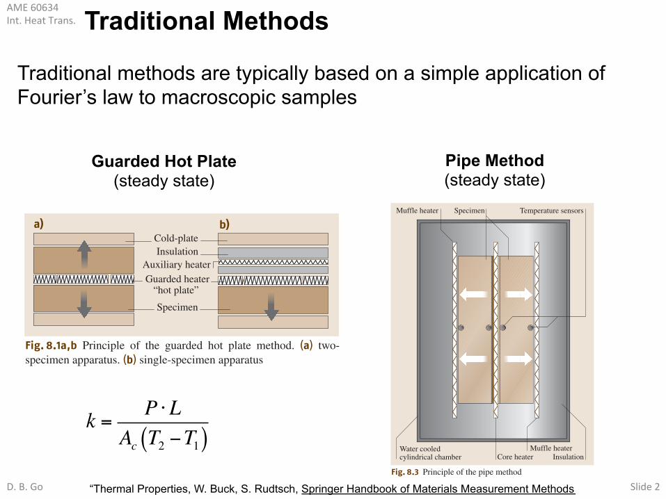
Traditional Methods
Traditional methods are typically based on a simple application of Fourier’s law to macroscopic samples
Guarded Hot Plate (steady state)
402 Part C Measurement Methods for Materials Properties
8.1.1 Steady-State Methods
The principle of (one-dimensional) steady-state methodsfor the determination of the thermal conductivity is de-rived from (8.2) and based on the measurement of a heatflux and a temperature difference according to
! = qdT2 ! T1
= PdA (T2 ! T1)
. (8.7)
In many cases the heat flux q is determined by the meas-urement of a power P released in an electrical heaterdivided by the area A of the sample. The temperaturedifference T2 ! T1 is determined between two oppositesurfaces of the specimen having a separation of d.
The typical sample geometry and the configura-tion of a measurement system for thermal conductivitymeasurements depend most strongly on the magni-tude of the thermal conductivity. When the thermalconductivity of a material is low, the samples are usu-ally flat disks or plates. In the case of a high thermalconductivity the sample geometry is formed by a cylin-der or rod. According to the relationship between thesample geometry (assumed to be cylindrical) and thedirection of the heat flow, axial and radial heat flowmethods of measuring the thermal conductivity are dis-tinguished.
Guarded Hot Plate and Cylinder MethodThe guarded hot plate method can be used for the deter-mination of the thermal conductivity of nonmetals suchas glasses, ceramics, polymers and thermal insulationmaterials but also for liquids and gases in the tempera-ture range between about 80 K and 800 K. The geometryof the sample or sample chamber is a plate or a cylinderwith axial heat flow. Depending on the thermal conduc-tivity and homogeneity of the material under investiga-tion, the sample thickness varies between a few millime-ters and a few decimeters. There are two different types
Guarded heater “hot plate”
Specimen
Cold-plateInsulation
Auxiliary heater
a) b)
Fig. 8.1a,b Principle of the guarded hot plate method. (a) two-specimen apparatus. (b) single-specimen apparatus
of guarded hot plate instruments: the two-specimen andthe single-specimen apparatus shown in Fig. 8.1.
Guarded hot plate instruments consist of one or twocold plates, a hot plate and a system of guard heatersand thermal insulation. The cold plates are liquid-cooledheat sinks, the hot plate is electrically heated. To makesure that the heat released in the hot plate is passed onlythrough the sample, the hot plate is surrounded by guardheaters and thermal insulation. This minimizes the heatlosses from the hot plate and ensures the high accu-racy of this method. With guarded hot plate instrumentsrelative expanded uncertainties of thermal conductiv-ity measurements of about 2% can be achieved. Thereare two main sources of uncertainty in thermal conduc-tivity measurements: the heat flux and the temperaturedifference determination. The major contributions toheat flux errors are heat losses from the hot plate andthe heat exchange between the sample and the sur-rounding medium. With increasing thermal resistanceof the sample (insulation materials) these sources ofuncertainty become dominant.
The advantage of the two-specimen apparatus is thatheat losses from the hot plate can be controlled moreeffectively because of the symmetric specimen arrange-ment. In contrast to the single-specimen method, onlysolid materials can be investigated. This is because of theinfluence of convection on thermal conductivity meas-urements. In order to avoid convection, the sample mustbe heated from the top.
The cylinder method with axial heat flow can beused for thermal conductivity measurements of met-als with thermal conductivities up to 500 W m!1 K!1
in a temperature range between about 4 K and 1000 K.Comparing the principle of operation and the mathe-matical model, the cylinder method and the guarded hotplate method fully agree. The most important differenceis the sample geometry, which is a flat plate or disk forthe guarded hot plate method and a long cylinder or rodfor the cylinder method. This is due to the fact that themain difficulty for measurements of materials with highthermal conductivity (e.g. metals) is the determinationof the temperature difference. In this case the contact re-sistances between the sample and the heater and betweenthe sample and the cold plate must be considered. Theminimization and determination of the resulting temper-ature drop across these thermal contact resistances is themost important criterion for the optimization of this typeof instrument.
Therefore, guarded hot plate and cylinder methodare realizations of the same measurement principle op-timized for different ranges of thermal conductivity.
PartC
8.1
k = P ⋅LAc T2 −T1( )
“Thermal Properties, W. Buck, S. Rudtsch, Springer Handbook of Materials Measurement Methods
Pipe Method (steady state)
404 Part C Measurement Methods for Materials Properties
position. In most cases thermocouples are used becauseof their dual usability as temperature sensors and forvoltage-drop measurements. The result of measurementsby the direct heating method is the product of the thermalconductivity and the specific electric resistivity !"el.
!"el = (U3 !U1)2
4!2T2 ! (T1 + T3)
" . (8.8)
The specific electrical resistivity can be determined fromthe length l and cross-sectional area A of the sample,heating current Ih and voltage drop Uh according to
"el = Uh AIhl
. (8.9)
Pipe and Hot Wire MethodThe characteristic of this class of methods is radial heatflow in a cylindrical sample (diameter d1, length l).Figure 8.3 shows the principle of the pipe method.
A hole on the central axis of the sample containsthe core heater (diameter d2), which is a rod, tube orwire. Depending on the temperature range of interestthe sample is surrounded by a liquid-cooled heat sinkor a combination of muffle heater and water jacket.
Muffle heater Specimen Temperature sensors
Water cooledcylindrical chamber InsulationCore heater
Muffle heater
Fig. 8.3 Principle of the pipe method
Axial heat losses can be minimized by additional endguard heaters or a special sample geometry, i. e. a largelength-to-diameter ratio. The thermal conductivity is de-termined by the measurement of the radial heat flow #and the temperature difference between the inner andthe outer surface of the sample according to
! =# ln
#d2d1
$
2$l (T1 ! T 2). (8.10)
Because of its simple design modified versions of thistechnique have been used for solids covering the ther-mal conductivity range between insulation materials%20 mW m!1 K!1& and metals
%200 W m!1 K!1& for
temperatures between room temperature and 2770 K.Transient modifications to this technique for the simulta-neous determination of thermal conductivity and thermaldiffusivity are of increasing interest (Sect. 8.1.2).
8.1.2 Transient Methods
With the availability of modern computers and dataacquisition systems transient methods have become in-creasingly popular. The advantages of transient methodsare that much less time is needed for the experiments andthat various thermal properties can be determined in thesame measurement cycle. A typical measurement dura-tion of one hour for steady-state methods is reduced toa few minutes or to a subsecond interval for transientmethods. In many cases the temperature measurementat two opposite surfaces of the sample is replaced bya temperature measurement as a function of time at onlyone position. This makes the design of instruments fortransient measurements straightforward in comparisonto steady-state methods and can improve the accuracyof the results.
Transient Hot Wire and Hot Strip MethodMost thermal conductivity measurements of liquids,gases and powders are carried out by means of the tran-sient hot wire method, a modification of the steady-statepipe method with a cylindrical specimen geometry andradial heat flow. The pipe is replaced by a thin plat-inum wire or nickel strip [8.2, 3]. For measurements onsolids the wire is embedded in grooves between twoequally sized specimens. Considerable care is needed inthe sample preparation to achieve sufficiently low ther-mal contact resistances between solid samples and theheating wire. Therefore, the use of a thin metal foil strip(hot strip method) instead of the heating wire has be-come increasingly popular for measurements on solids.
PartC
8.1

AME 60634 Int. Heat Trans.
D. B. Go Slide 3
Traditional Methods
Thermal Properties 8.1 Thermal Conductivity and Specific Heat Capacity 403
Heat Flow Meter and Comparative MethodThe main disadvantage of steady-state methods is thatthey are very time consuming. This is because the wholesystem of specimen and guard heaters must reach ther-mal equilibrium in order to avoid unaccounted heatlosses and deviations from steady-state conditions. Thebasic idea of the heat flow meter and the comparativemethod is the determination of the (axial) heat flux bymeans of the measurement of a temperature drop acrossa thermal resistor. This is in analogy to the determi-nation of a current by the measurement of a voltagedrop across an electrical resistor. The implementation ofthis idea for heat flux measurements is carried out ei-ther by the use of a reference sample with well-known(certified) thermal resistance or by means of a heat fluxsensor. Most heat flux sensors consist of a series con-nection of thermocouples across a thermal resistor, e.g.a thin ceramic or plastic plate. The measured signal isa thermovoltage proportional to the temperature dropacross the plate. Usually a heat flux sensor is calibratedin a steady-state temperature field with well-known heatflux, e.g. in a guarded hot plate apparatus.
The design of a heat flow meter apparatus is verysimilar to that of the single-specimen guarded hot plateinstrument. Instead of the main heater a heat flux sensoris used. In some cases a second heat flux sensor at thecold plate is applied to determine radial heat losses andto reduce the measurement duration. This is of particularadvantage for measurements of insulation materials. Toavoid radial heat losses the lateral surfaces of the sampleare surrounded by thermal insulation or additional guardheaters.
If a reference sample for heat flux measurements isused, the sample and reference samples are piled uponone another in a temperature field (series connection ofthermal resistors). The temperature drops across bothsample and reference sample are measured and com-pared (comparative method). To correct for radial heatlosses two reference samples are mostly used and theinvestigated sample is sandwiched between them. Un-der steady-state conditions the heat flux at each pointof the stack is the same. In that case the ratio of thethermal resistances of the sample and reference sampleis equal to the ratio of the corresponding temperaturedrops. In contrast to the guarded hot plate method theheat flow meter and the comparative method are rel-ative and not absolute methods. The heat flow metermethod is mostly used for insulation materials and poly-mers (! < 0.3 W m!1 K!1), in some cases for glassesand ceramics, i. e. for materials with thermal conduc-tivities less than about 5 W m!1 K!1. In contrast, the
typical application range of the comparative techniqueis the investigation of metals, ceramics and glasses hav-ing thermal conductivities above 1 W m!1 K!1. Typicalupper temperature limits are about 200 "C for the heatflow meter method and about 1300 "C for the compar-ative method. The measurement uncertainties are about3% for insulation materials near room temperature andbetween 10% and 20% at high temperatures.
Direct Heating (Kohlrausch) MethodThe disadvantages of steady-state thermal conductivitymeasurement methods are the long equilibration timeneeded to reach steady-state conditions and the difficultquantification of heat losses, in particular at high tem-peratures. These can be avoided using the direct heatingmethod, although this can only be used for materials withsufficiently high electrical conductivity, such as metals.Typically samples are wires, pipes or rods with a diam-eter d between 0.5 mm and 20 mm and a length l between50 mm and 500 mm. Figure 8.2 shows the schematic ofthe most popular design of the direct heating method.
The sample is placed in a vacuum chamber, clampedbetween two liquid-cooled heat sinks and heated bya sufficiently high electrical current Ih to achieve sampletemperatures in the range 400–3000 K. Temperaturesand voltage drops are measured at three positions; oneposition is in the middle of the rod, while the others areplaced symmetrically at equal distances from the middle
1
2
3
Power supply
Vacuumenclosure
Cylindricalguard heater
Tguard
Specimen
T1, T2, T3
U3 –U1
Fig. 8.2 Principle of the direct heating method
PartC
8.1
Direct Heating
“Thermal Properties, W. Buck, S. Rudtsch, Springer Handbook of Materials Measurement Methods
Run electric current through the sample to heat it by Joule heating: voltage drop (ΔU) and temperature difference (ΔT) across sample related to thermal conductivity and electrical resistivity
kρelec =(U3 −U1)
2
4 2T2 − T1 +T3( )"# $%
ρelec =ΔU ⋅Aci ⋅L

AME 60634 Int. Heat Trans.
D. B. Go Slide 4
Thermal Properties 8.1 Thermal Conductivity and Specific Heat Capacity 401
ity to exchange heat with the environment (thermalimpedance) and is defined according to
e =!
!"cp . (8.6)
Knowing the thermal diffusivity and thermal effusivity,other complementary materials properties, e.g. ! and"cp, can be calculated.
Based on the fundamental laws of heat conduc-tion and storage three different attempts to measurethese thermophysical properties can be distinguished.The first one is the steady-state approach using (8.2)in order to determine the thermal conductivity. Steady-state conditions mean that the temperature at each pointof the sample is constant, i. e. not a function of time.The determination of the thermal conductivity is basedon the measurement of a heat flux and a temperaturegradient, i. e. mostly a temperature difference betweenopposite surfaces of a sample. If the specific heat cap-acity is the property of interest, a calorimetric method
Table 8.1 Comparison of measurement methods for the determination of thermal conductivity and thermal diffusivity
Method Temperature Uncertainty Materials Merit Demeritrange
Guarded hot 80–800 K 2% Insulation materials, High accuracy Long measurement time,plate plastics, glasses large specimen size,
low conductivity materials
Cylinder 4–1000 K 2% Metals Temperature range, Long measurement timesimultaneous determination ofelectrical conductivity andSeebeck-coefficient possible
Heat flow meter !100–200 "C 3–10% Insulation materials, Simple construction Measurement uncertainty,plastics, glasses, and operation relative measurementceramics
Comparative 20–1300 "C 10–20% Metals, ceramics, Simple construction Measurement uncertainty,plastics, plastics and operation relative measurement
Direct heating 400–3000 K 2–10% Metals Simple and fast measurements, only electrically(Kohlrausch) simultaneous determination conducting materials
of electrical conductivity
Pipe method 20–2500 "C 3–20% Solids Temperature range Specimen preparation,long measurement time
Hot wire, 20–2000 "C 1–10% Liquids, gases, low Temperature range, Limited to lowhot strip conductivity solids fast, accuracy conductivity materials
Laser flash !100–3000 "C 3–5% Solids, liquids Temperature range, most Expensive, not forsolids, liquids and powders, insulation materialssmall specimen, fast, accuracyat high temperatures
Photothermal 30–1500 K Not suffi- Solids, liquids, Usable for thin films, Nonstandard, knowledgephotoacoustic ciently gases, thin films liquids and gases about accuracy
known
based on (8.1) is used. In this case, heat is supplied toa sample that is isolated from the surroundings, and thechange of the (mean) sample temperature is measured.The third approach is the simultaneous determinationof both properties by a transient technique. For that pur-pose numerous solutions of the transient heat conductionequation based on one- (8.3), two-, or three-dimensionalgeometries have been derived.
The main experimental problem for all methods forthe determination of thermal properties is that ideal ther-mal conductors or insulators do not exist. In comparisonto electrical transport the ratio of thermal conductivitiesof the best conductors and the best insulators is many or-ders of magnitudes smaller. Therefore, instruments forthe determination of thermal properties are often opti-mized or restricted for a specific class of materials ortemperature range [8.1]. Table 8.1 gives an overview ofthe most important methods used for the measurementof thermal conductivity and thermal diffusivity.
PartC
8.1
“Thermal Properties, W. Buck, S. Rudtsch, Springer Handbook of Materials Measurement Methods

AME 60634 Int. Heat Trans.
D. B. Go Slide 5
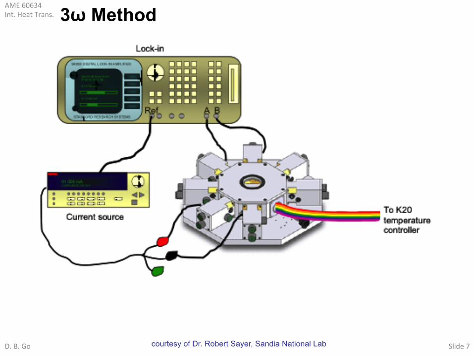
Periodic Heating Approaches • Periodic heating approaches are often favored
– Give rise to periodic thermal response
– Minimize radiation losses (non-steady heating)
– Solve heat equation to determine periodic component (fairly simple)
– Lock-in measurement system to detect periodic component (fairly cheap)
Stanford Research SR830 Lock in Amplifiers

AME 60634 Int. Heat Trans.
D. B. Go Slide 6
3ω Method
Developed for measurement of thermal conductivity of thin films. - use thin metal strip as both heater and thermometer by applying AC signal
substrate thin film
thin metal strip
~ V
AME 60634 Int. Heat Trans.
D. B. Go Slide 7
3ω Method
courtesy of Dr. Robert Sayer, Sandia National Lab
AME 60634 Int. Heat Trans.
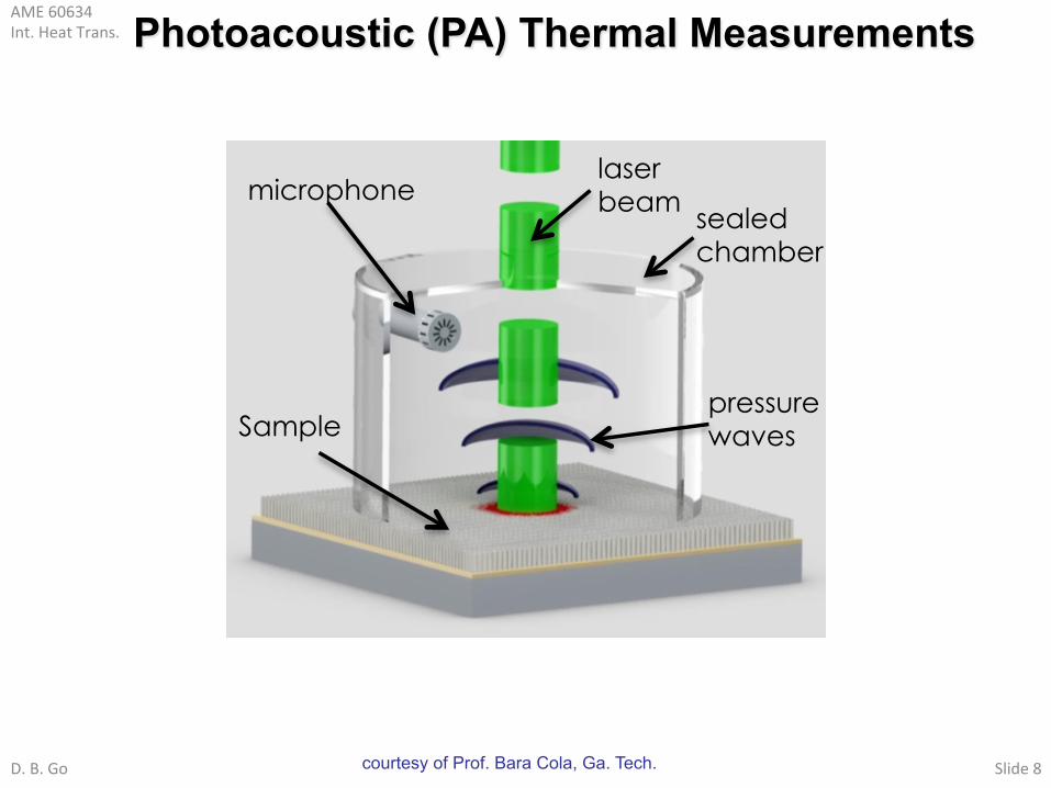
D. B. Go Slide 8 courtesy of Prof. Bara Cola, Ga. Tech.
laser beam microphone
sealed chamber
Sample pressure waves
Photoacoustic (PA) Thermal Measurements

AME 60634 Int. Heat Trans.
D. B. Go Slide 9
Photoacoustic (PA) Thermal Measurements
• Heat equation for multilayer material with modulated incident light:
θi (x,t) = θi ,s
θi =Ti −Tambwhere,
Si wafer
CNT array
80 nm Ti
Laser beam
Layer 3 (N+1)
Layer 2 (N)
Layer 1
Layer 0
He
RSi-Ag
x
Ag foil
θi (x,t) =θi ,t +θi ,s + θi ,s
Solution consist of three parts:
Transient Steady periodic
Steady
Lock-in amplifier only senses the steady periodic solution thus the desired solution is:
!2"i (x,t)!x2
=1
# i
!"i (x,t)!t
$%i Io
2ki& 1+ e j' t( ) & e%i x$ li( ) & exp $%mLm
m= i+1
N
()*+
,-.
courtesy of Prof. Bara Cola, Ga. Tech.

AME 60634 Int. Heat Trans.
D. B. Go Slide 10
φ = Arg(B N+1)−π / 4Phase:
A=pambBN+12TambLgag
Amplitude:
Photoacoustic (PA) Thermal Measurements
dp = pT< θN+1,s >=
pambBN+12TambLgag
e j (ωt−π /4)
Ideal gas relation:
φMeasured −φTheoretical"# $%
2
n = 1
q
∑ q < 0.1°
Least squares regression for q different laser frequencies:
Uncertainty:
Measured signal
+/- 0.2° phase shift (more stable than amplitude)
Thermal contact resistance
+/- 0.5 mm2K/W
θN+1,s = B N+1e−σ N+1xe jωt
• Applying B.C.’s, temperature change in gas layer:
courtesy of Prof. Bara Cola, Ga. Tech.

AME 60634 Int. Heat Trans.
D. B. Go Slide 11
silicon/copper substrates at room temperature
B.A. Cola et al., J. Appl. Phys. 101, 054313 (2007)
courtesy of Prof. Bara Cola, Ga. Tech.
Enhanced Resolution for CNT Interfaces
0
2
4
6
8
10
12
0.1 0.2 0.3 0.4 0.5Pressure (MPa)
Ther
mal
resi
stan
ce (m
m2 K
/W)
1-D reference bar measurementPhotoacoustic measurement
AME 60634 Int. Heat Trans.
D. B. Go Slide 12
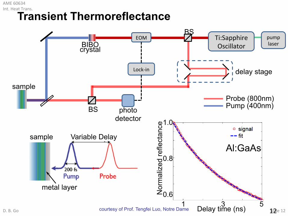
photo detector
Pump (400nm) Probe (800nm)
Ti:Sapphire Oscillator
pump laser
EOM BIBO crystal
Lock-‐in delay stage
BS
BS
sample
sample
metal layer
Al:GaAs
Delay time (ns)
Nor
mal
ized
refle
ctan
ce
1 3 5
Variable Delay
0.6
0.8
1.0
Transient Thermoreflectance
12 courtesy of Prof. Tengfei Luo, Notre Dame
AME 60634 Int. Heat Trans.
D. B. Go Slide 13
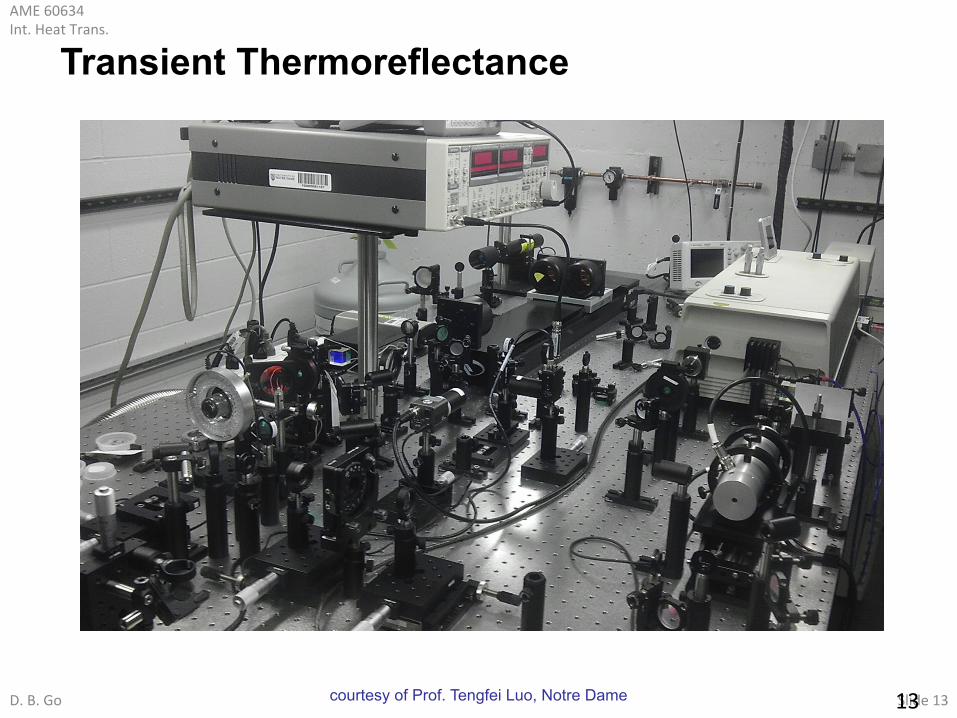
Transient Thermoreflectance
13 courtesy of Prof. Tengfei Luo, Notre Dame

AME 60634 Int. Heat Trans.
D. B. Go Slide 14
Bi-layer Pump-Probe Measurement
Substrate (With Unknown ProperQes)
Al (Metal Transducer Layer)
Pump beam size: 20 – 100 um Probe beam size: 10 – 20 um
14 courtesy of Prof. Tengfei Luo, Notre Dame

AME 60634 Int. Heat Trans.
D. B. Go Slide 15
Tri-layer Pump-Probe Measurement
Glass
Al (Metal Transducer Layer)
Liquid (With Unknown ProperQes)
15 courtesy of Prof. Tengfei Luo, Notre Dame

AME 60634 Int. Heat Trans.
D. B. Go Slide 16
Silicon
Sapphire Quartz
Fused Silica
Water
Hexadecane 0.1
1
10
100
0.1 1 10 100
Measured (W
/mK)
Reference values (W/mK)
MEASURED AND REFERENCE THERMAL CONDUCTIVITY VALUES
16 courtesy of Prof. Tengfei Luo, Notre Dame