Thermal conductivity of some indigenous refractoriesdetermining thermal conductivity of refractory...
8
Thermal conductivity of some indigenous refractories K. C. Ray, P, C. San, N. S. Sarkar Er M. R. K. Rao National Metallurgical Laboratory, Jamshedpur- Introduction An apparatus for determining the thermal conductivity of refractory bricks has been fabricated based on the design of Blakeley & Cobb" in which a blackened brass plate calorimeter is used to determine the heat transmitted through a refractory brick. The brick is In direct contact with heated chro- mium plated copper plate below and the calorimeter above. The blackened calorimeter is heated by the conduction of heat coming through the refractory brick. But since the calorimeter is exposed on the surface to the atmos- phere it also loses heat by convection and by radiation. The heat lost by convection and ty radiation cf this calorimeter is calculatai as per the method used byBlakely & Cobb. This apparatus is simple and can be fabrica- ted Indigenously at a cheaper cost corn_ pared to a more sophisticated expen- sive and elaborate apparatus used for determining thermal conductivity of refractory bricks. The apparatus fabri. cated has Its limitation in that the Maximum hot face temperature Is 1000°C. An apparatus fcr the determination of thermal conductivity of refractory bricks has been described. Thermal conductivities of different types of commercial bricks such as alumina silicates, silica and insulating bricks have been measured. These results are discussed in relation to the porosity and bulk density of the bricks. Description of the apparatus A design2 of the apparatus as per the design of Blakely and Cobb' was fabricated in N. M. L. Tha thermal conductivity app::.ztus consists cf a rectangular mild steel sheet cas. ing open at the to? and nned a:I round with asbestos boar) of i" thickness, A layer of firebrick Is placed at the bottom over which an insulating refrac- tory slab of x 3° grooved for hold- ing Kanthal heating element is placed. The Kanthal wire In coiled form is embeded in the grooves. A chromium plated copper plate 9° x Is placed over the heater such that it covers the heater and the heater grooves are so designed that the copper plate Is uni- 252 ."°` Per ••••••-"- ■
Transcript of Thermal conductivity of some indigenous refractoriesdetermining thermal conductivity of refractory...

Thermal conductivity of some indigenous refractories
K. C. Ray, P, C. San, N. S. Sarkar Er M. R. K. Rao
National Metallurgical Laboratory, Jamshedpur-
Introduction
An apparatus for determining the
thermal conductivity of refractory
bricks has been fabricated based on the
design of Blakeley & Cobb" in which a
blackened brass plate calorimeter is
used to determine the heat transmitted
through a refractory brick. The brick
is In direct contact with heated chro-
mium plated copper plate below and
the calorimeter above. The blackened
calorimeter is heated by the conduction
of heat coming through the refractory
brick. But since the calorimeter is
exposed on the surface to the atmos-
phere it also loses heat by convection
and by radiation. The heat lost by
convection and ty radiation cf this
calorimeter is calculatai as per the
method used byBlakely & Cobb. This
apparatus is simple and can be fabrica-
ted Indigenously at a cheaper cost corn_
pared to a more sophisticated expen-
sive and elaborate apparatus used for
determining thermal conductivity of
refractory bricks. The apparatus fabri.
cated has Its limitation in that the
Maximum hot face temperature Is
1000°C.
An apparatus fcr the determination
of thermal conductivity of refractory
bricks has been described. Thermal
conductivities of different types of
commercial bricks such as alumina
silicates, silica and insulating bricks
have been measured. These results
are discussed in relation to the
porosity and bulk density of the
bricks.
Description of the apparatus
A design2 of the apparatus as per the design of Blakely and Cobb' was
fabricated in N. M. L. Tha thermal
conductivity app::.ztus consists cf a
rectangular mild steel sheet cas.
ing open at the to? and nned a:I round
with asbestos boar) of i" thickness,
A layer of firebrick Is placed at the
bottom over which an insulating refrac-
tory slab of x 3° grooved for hold-
ing Kanthal heating element is placed.
The Kanthal wire In coiled form is
embeded in the grooves. A chromium
plated copper plate 9° x Is placed
over the heater such that it covers the
heater and the heater grooves are so
designed that the copper plate Is uni-
252
."°` Per ••••••-"-■
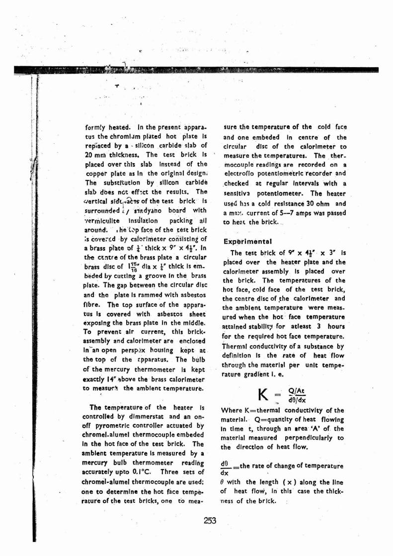
form{y heated. in the present appara-
tus the chromiJm plated hot plate is
rep aced by a - silicon carbide slab of
20 mm thickness. The test brick is
placed over this slab instead of the copper plate as in the original design.
The substitution by silicon carbide
slab does nGt efN.ct the results. The
vertical strtc,,s of the test brick is
surrounded 'A./ sendyano board with
•ermiculite Instilation packing all
around. he L■p face of the test brick
;s coverf:.d by calorimeter consisting of
a brass plate of i thick x 9" x 41". In
the centre of the brass plate a circular
brass disc of dia x t" thick Is em_
beded by cutting a groove in the brass
plate. The gap between the circular disc
and the plate Is rammed with asbestos
fibre. The top surface of the appara-
tus is covered with asbestos sheet exposing the brass plate in the middle. To prevent air current, this brick-
assembly and calorimeter are enclosed
in-an open persp±x housing kept at
the top of the rpparatus. The bulb
of the mercury thermometer is kept
exactly IC above the brass calorimeter to messy." the ambient temperature.
The temperature of the heater is controlled by dimmerstat and an on-
off pyrometric controller actuated by
chromel.alumel thermocouple embeded
In the hot face of the test brick. The
ambient temperature is measured by a mercury bulb thermometer reading accurately upto 0.1°C. Three sets of
chromel-alumel thermocouple are used;
one to determine the hot face tempe-
rature of the test bricks, one to mea-
sure the temperature of the cold face
and one embeded In centre of the
circular disc of the calorimeter to
measure the temperatures. The ther-mocouple readings are recorded on a electroflo potentiometric recorder and
checked at regular intervals with a
sensitive potentiometer. The heater
used has a cold resistance 30 ohm and
a ma;.. current of 5--7 amps was passed
to heat the brick.
Experimental
The test brick of 9" x x 3" is
placed over the heater plate and the
calorimeter assembly is placed over
the brick. The temperatures of the
hot face, cold face of the test brick, the centre disc of the calorimeter and
the ambient temperature were meas-
ured when the hot face temperature
attained stabilly,1 for atleast 3 hours
for the required hot face temperature.
Thermal conductivity of a substance by definition Is the rate of heat flow
through the material per unit tempe-
rature gradient I. e.
Q/At _ dO/dx
Where K=thermal conductivity of the
material. Q=quantity of heat flowing
in time t, through an area 'A' of the
material measured perpendicularly to
the direction of heat flow.
dO —the rate of change of temperature dx
0 with the length ( x ) along the line of heat flow, in this case the thick-
ness of the brick.
253
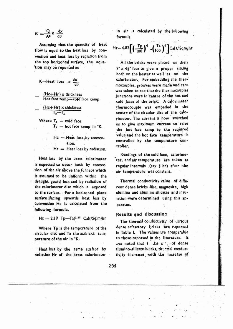
In air is calculated by the following
formula
[__Tp 1
Ta Hr=4.82(
100 7 100 J iCals/Sqm/hr
All the bricks were placed on their
9" x 41" face to give a proper sitting
both on the heater as well as on the
calorimeter. For embedding the ther-
mocouples, grooves were made and care
was taken to see that the thermocouples
junctions were in centre of the hot and
cold faces of the brick. A calorimeter
thermocouple was embeded in the
centre of the circular disc of the calo-
rimeter. The current Is now switched
on to give maximum current to raise
the hot face temp to the required
value and the hot face temperature is
controlled by the temperature con-
troller.
Readings of the cold face, calorime-
ter, and air temperature are taken at
regular intervals (say 1 hr) after the
air temperature was constant.
Thermal conductivity value of diffe-
rent dense bricks like, magnesite, high
alumina and alumino silicates and Insu-
lation were determined using this ap-
paratus.
Results and di3cussior.
The thermal conductivity of ,arlous
dense refractory hicks are r4portc4
in Table I. The values -..re co;aparabie
to those reported In th; literature. It
was noted that I c of dense
alumino-silicate h irks, th; -mai conduc-
tivity Increases with the increase of
254
Qx dx
At dO
Assuming that the quantity of heat
flow is equal to the heat loss by con-
vection and heat loss by radiation from
the top horizontal surface, the equa-
tion may be reported as
K=Heat loss x ddb
(Hc+Hr) x thickness Hot face temp—cold face temp
(Hc-I-Hr) x thickness T2 —
Where T1 = cold face
T2 = hot face temp in °K
Hc = Heat loss by convec-
tion.
Hr = Heat loss by radiation.
Heat loss by the brass calorimeter
Is expected to occur both by convec
tion of the air above the furnace which
Is assumed to be uniform within the
draught guard box and by radiation of
the calorimeter disc which. Is exposed
to the surface. For a horizontal plane
surface !facing upwards heat loss by
convention Hc Is calculated from the
following formula.
Hc = 2.19 Tp—Ta)1.25 Cals/Sq.m/hr
Where Tp is the temperature of the
circular disc and Ta the arabie+.t tem-
perature of the air in K.
Heat loss by the same sat face by
radiation Hr of the brass calorimeter

65 60 70
POROSITY 80 90
0.8
0.7
0.5
w 02
01
alumina content of the brick, apart
from the effects oi Lulk density and
porosity.
Table II illust;.:tes the thermal con-
ductivity, bulk 4ensiti'. and porosity of
the different types of Insulating bricks
made from different raw materials such
as fireclay, silica, vermiculate and wol-
lastonite (calcium silicate). It was ob-
served that the thermal conductivity of porous bricks is directly related to
the porosity or bulk density of the
bricks irrespective of the type of raw
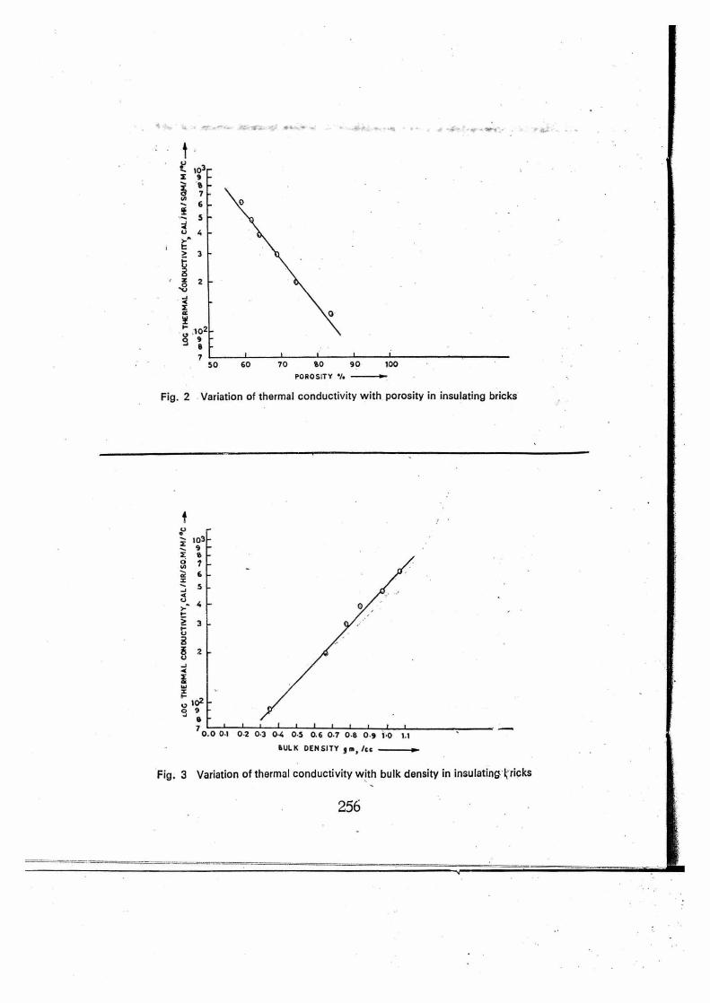
materials from which it was manufac-tured when the porosity of the bricks ara more than 50%. This is illustrated In Fig. I, 2 and 3, The relative depen-dence of the thermal conductivity of
porous Insulating bricks shows that
thermal conductivity decreases as the
porosity of the irsulating brick in-
creases. Fig. .2 illustrates the varia-
tion of log of thermal conductivity
of insulating bricks with porosity.
The logarithm of thermal conductivity
bears straight line relationship with
the porosity ( 50% to 85% ) of the
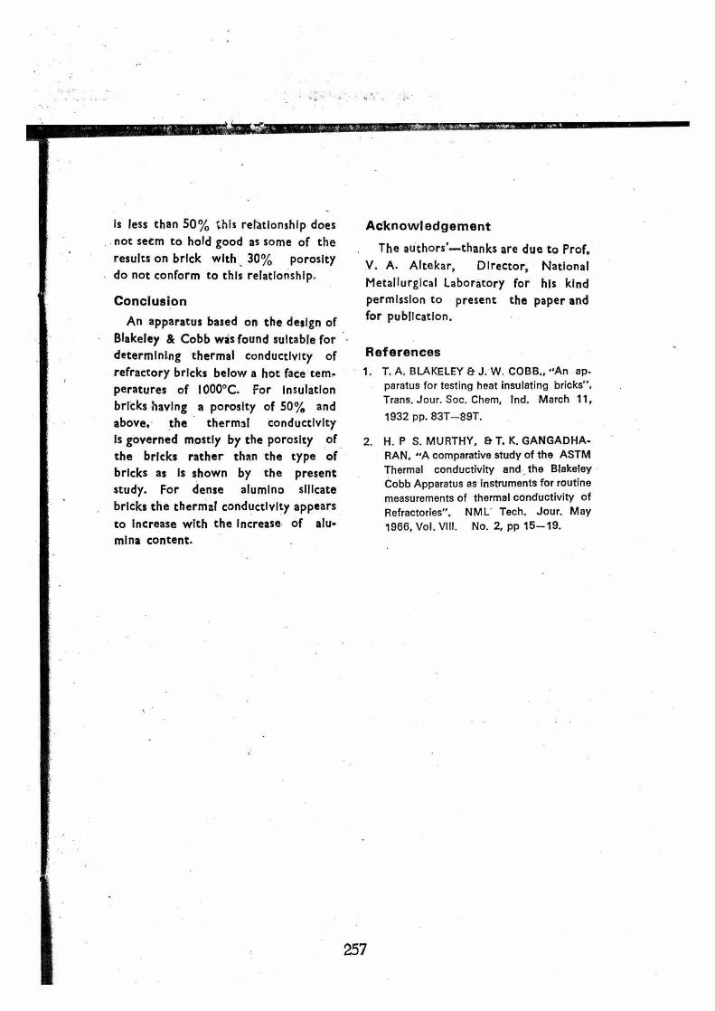
insulating bricks. Similarly Fig. 3
illustrates that the logarithm of thermal
conductivity Increases linearly with the increase in bulk density. It seems that in the case of Insulating bricks of
porosity above 50%, the effect of type
of raw material such as fireclay, silica,
vermiculate etc., have minor influence
on the thermal conductivity values.
However, if the porosity of the brick
Fig. 1 Relationship of thermal conductivity with porosity of Insulating bricks
255
0 z 2
I 03 -... 9 X 0
rc 6 5
>-. 4
3
0 0 0.1 0.2 0.3 0.4 0.5 0.6 0.7 0.5 0.9 1.0 1.1
SULK DENSITY 5 555, /cc
103— X 9
11 N 7
6
5
10
7 50 60 70 90 90 100
POROSITY 1.
Fig. 2 Variation of thermal conductivity with porosity in insulating bricks
Fig. 3 Variation of thermal conductivity with bulk density in insulating kricks
256
Is less than 50% this relationship does
not secm to hold good as some of the
results on brick with 30% porosity
do not conform to this relationship.
Conclusion
An apparatus based on the design of
Blakeley & Cobb was found suitable for
determining thermal conductivity of
refractory bricks below a hot face tern-
peratures of 1000°C. For Insulation
bricks having a porosity of 50% and
above. the thermal conductivity
is governed mostly by the porosity of
the bricks rather than the type of
bricks as is shown by the present
study. For dense alumino silicate
bricks the thermal conductivity appears
to increase with the increase of alu-
mina content.
Acknowledgement
The authors'—thanks are due to Prof.
V. A. Altekar, Director, National
Metallurgical Laboratory for his kind
permission to present the paper and
for publication.
References
1. T. A. BLAKELEY Et J. W. COBB., "An ap-
paratus for testing heat insulating bricks".
Trans. Jour. Soc. Chem, Ind. March 11,
1932 pp. 83T-89T.
2. H. P S. MURTHY, Et T. K. GANGADHA-
RAN, "A comparative study of the ASTM
Thermal conductivity and the Blakeley
Cobb Apparatus as instruments for routine
measurements of thermal conductivity of
Refractories". NML Tech. Jour. May
1966, Vol. VIII. No. 2, pp 15-19.
257

10 11'6
10 CO
c, 10 CO ;1 10 0 p
<V •al to
Hig
h h
eat
dut
y
Hig
h a
lum
ina
50
Hig
h s
ilica
70
0 7+ 0 O "--- = -o -.... • E
u; c., • 43* e .4. - co
co to r. 0) PO C,, CV
/0 CO
cz t-• 5-1 t■ ..Ne
0.1 ...... 03 0 0- 3-- .-e
9 9
ri 1 A E.-
,- -re 4)
O .c in
I-
0 Si
C. e i = • 0 00 ..f. 07 CI CA Cl C1 CA
•
•
tn. d Ci CO Ci C4 CO CO Cg CO
to- < v) >
. 0
1 d .1 CO cl 03 1.4 00
E •-1 M•00 CO
03 01
>,.. 4., 7; O ....0 0) CO 10 1- 0- CO uo C- P-I .111 O 0 CZ 06 C•6 a a . C4 01
a. E i-sv
0 =,0 00 <6 e 0 t- 0) to ■0 10 0
CO 1-1 10 10 CO
0 O 0
.I.. 0 0
, 0. C- ,-I CI C-.. c.4
-= E IC 00 M CO O 0 5,, CO el. CO .1'1
O 4...
O u
O 0
4- O. 0 0 03 0 0
o '" E c, CO 0 CO 0 CO 0 00 0 CO
2r
— O
C
0
0
C C
ti
-13
a.
ci. 0. co
4,)
O
O 0.,
ca
Mark
ing
of
t he b
rick
Aci
d r
esis
tanc
e
Hig
h a
lum
ina
70

02 4
0 '17 .0 0 .0 4.° •1.• 0 C) C
CO CO
2
Ol
co
0 -C
0
0
E O
C.
o.
C O
.0
PL.
0 O
5 U « o E
. 9. 0
E 70.
(9 O . ty
01C
fl'
Ci
6 g
o 2 o..
a. E
c O 2
o to • 0 • a.
E o 0 '0'
o O 0 CO •I■ C. • E O
Wo
last
on
ite in
sula
tio
n
0) C ZS
C
5
Sili
ca ins
ula
tio
n
Fire
clay
insu
latio
n
Hot
fa
ce
insu
lati
on
Wo
llast
on
ite
insu
lati
on
Sili
ca insu
lati
on
Ver
mic
ulite
in
sula
tio
n
.10 00 m n••1° 00 00 00 0 Cl lO m -r co. oo O O;
on N N in P. oo CO
- 6
N ̀"? ev - 06 C•1
co CO co
CO
o
▪
D
7n. ▪ •-• ▪ 10 Cl 111 Cl
0 0
co co oo 0D co Cl
IQ m In O
cCi Io In
0 oo
• LCD CS N e°I
OD
to C