
Thermal Combustion of Rice Husk to Generate …Thermal Combustion of Rice Husk to Generate Product...
15
International Journal of Engineering and Techniques - Volume 4 Issue 2, Mar-Apr 2018 ISSN: 2395-1303 http://www.ijetjournal.org Page 662 Thermal Combustion of Rice Husk to Generate Product Gas for Engine Applications M.Mathanmohan 1 , S.Vivekanandan 2 1 Research Scholar, 2 Associate Professor,Department Of Mechanical Engineering, Annamalai University, Chidambaram– 608002, Tamil Nadu, India Introduction Technology of the gasification has shown a number of ups and downs since its first appearance. It appears that interest in gasification research correlates closely with the relative cost and availability of liquid and gaseous fossil fuels. Gasifiers are of two main types, fixed bed and circulating fluidized bed, with variations with in each type and specific characteristics to determine the need for and extent of feedstock preparation/pre-treatment In the thermal combustion process, solid biomass is broken down to produce a combustible gas by the use of heat in an oxygen starved environment [2]. Heat from gasification is generated through partial combustion of the biomass material. The chemical breakdown of fuel and internal reactions result in a combustible gas usually called "producer gas". The main combustible gases are H 2 and CO, but small amounts of methane, ethane and acetylene are also produced. Gasification efficiency is dependent on the gasifier used, fuel type, fuel moisture content and fuel geometry. Fuel gas from air blown gasifier has low calorific value (around 5MJ/m 3 ) and fuel gas from oxygen fed gasifier has a medium heating value (1020 MJ/m 3 ). This gas can either be used onsite to produce heat and power may converted into substitute like methane and methanol. RESEARCH ARTICLE OPEN ACCESS Abstract: Increasing demand of fuel leads to increases in the fuel rates, due to depletion of the available fossil fuel. So, the need of alternative source of energy to meet the rural/urban demand. The combustible gas from agriculture biomass is plays a major potential sources for energy production. As an agriculture country, India has large biomass resources nearly 40 to 60 percentage of agriculture residues either put to inefficient use. Thermal combustion is a versatile thermo-chemical conversion process which produces a gas mixture of H 2 , CO and CH 4 that can be used for heat and power applications. In this work, a circulating bed gasifier was designed and developed to use rice husk as a feed stock. An investigation was also carried out to evaluate the performance and emission parameters of a CI engine developing rated power of 3.7 kW at a maximum speed of 1500rpm running on a dual fuel operation. The product gas was introduced in the inlet manifold of engine along with air flow rate at 40%, 60% and 80% load condition with respect to the full load. Diesel was injected into the engine as primary fuel and producer gas was injected as secondary fuel. The results obtained from the dual fuel mode were compared with standard primary fuel operation. Results indicated that a decrease in the consumption of diesel was observed upto 14 % when operated on dual fuel mode though there was a reduction in brake thermal efficiency. Oxides of nitrogen was found to be very low in dual fuel operation which is a great advantage over diesel alone, but CO and HC emission for dual fuel mode was found to be higher than diesel. Keywords— Biomass product, producer gas, Fluidized bed, IC engine.
Transcript of Thermal Combustion of Rice Husk to Generate …Thermal Combustion of Rice Husk to Generate Product...

International Journal of Engineering and Techniques - Volume 4 Issue 2, Mar-Apr 2018
ISSN: 2395-1303 http://www.ijetjournal.org Page 662
Thermal Combustion of Rice Husk to Generate
Product Gas for Engine Applications M.Mathanmohan
1, S.Vivekanandan
2
1Research Scholar,
2Associate Professor,Department Of Mechanical Engineering, Annamalai University,
Chidambaram– 608002, Tamil Nadu, India
Introduction
Technology of the gasification has shown a number of ups and downs since its first appearance. It
appears that interest in gasification research correlates closely with the relative cost and availability of
liquid and gaseous fossil fuels. Gasifiers are of two main types, fixed bed and circulating fluidized bed,
with variations with in each type and specific characteristics to determine the need for and extent of
feedstock preparation/pre-treatment
In the thermal combustion process, solid biomass is broken down to produce a combustible gas
by the use of heat in an oxygen starved environment [2]. Heat from gasification is generated through
partial combustion of the biomass material. The chemical breakdown of fuel and internal reactions result
in a combustible gas usually called "producer gas". The main combustible gases are H2 and CO, but small
amounts of methane, ethane and acetylene are also produced. Gasification efficiency is dependent on the
gasifier used, fuel type, fuel moisture content and fuel geometry. Fuel gas from air blown gasifier has low
calorific value (around 5MJ/m3) and fuel gas from oxygen fed gasifier has a medium heating value (1020
MJ/m3). This gas can either be used onsite to produce heat and power may converted into substitute like
methane and methanol.
RESEARCH ARTICLE OPEN ACCESS
Abstract: Increasing demand of fuel leads to increases in the fuel rates, due to depletion of the available fossil fuel.
So, the need of alternative source of energy to meet the rural/urban demand. The combustible gas from
agriculture biomass is plays a major potential sources for energy production. As an agriculture country, India has
large biomass resources nearly 40 to 60 percentage of agriculture residues either put to inefficient use. Thermal
combustion is a versatile thermo-chemical conversion process which produces a gas mixture of H2, CO and CH4
that can be used for heat and power applications. In this work, a circulating bed gasifier was designed and
developed to use rice husk as a feed stock. An investigation was also carried out to evaluate the performance and
emission parameters of a CI engine developing rated power of 3.7 kW at a maximum speed of 1500rpm running
on a dual fuel operation. The product gas was introduced in the inlet manifold of engine along with air flow rate
at 40%, 60% and 80% load condition with respect to the full load. Diesel was injected into the engine as primary
fuel and producer gas was injected as secondary fuel. The results obtained from the dual fuel mode were
compared with standard primary fuel operation. Results indicated that a decrease in the consumption of diesel
was observed upto 14 % when operated on dual fuel mode though there was a reduction in brake thermal
efficiency. Oxides of nitrogen was found to be very low in dual fuel operation which is a great advantage over
diesel alone, but CO and HC emission for dual fuel mode was found to be higher than diesel.
Keywords— Biomass product, producer gas, Fluidized bed, IC engine.

International Journal of Engineering and Techniques - Volume 4 Issue 2, Mar-Apr 2018
ISSN: 2395-1303 http://www.ijetjournal.org Page 663
The thermal efficiency of gasifiers in which producer gas is produced has been found to be less
than 60 percent and that of the gasifier-engine system to be 16-20 percent [3] the problem is more acute
and serious in nature when producer gas is used to run motor vehicles particularly for agricultural
operations. Agriculture based residue such rice husk are rich in sulphur and nickel contents is appreciated
for gasification as a commercial scale [4]. The literature review, reveals the effects of various parameters
on circulating bed gasification efficiency some investigations shows the quality of producer gas, with
respect to temperature, pressure, rate of feeding, equivalence ratio and effect of particle size of biomass
[5] .This works also consists the conversion of diesel engine running on diesel - cum producer gas as dual
fuel mode. Gasification process generate clean gas using Agro-industries residues such as RH run a diesel
engine with minor modification in inlet manifold can be made to operate on dual fuel efficiency [6].
There is insufficient data on the use of different biomass types and conditions to generate
producer gas as a supplementary fuel for diesel engine. Therefore an effort was made to generate
producer gas using rice husk as a studied and evaluating the process parameters with the help of
mathematical models using design matrix.
The major objective in this study was as follows:
• To design and fabricate a circulating bed gasifier.
• To use of rice husk as feed stock.
• To use primary fuel as diesel and secondary fuel as producer gas in a diesel engine.
• To introduce product gas partially with air into the inlet manifold of CI engine and
conduct the performance and emissions of varying loads conditions.
• To evaluate the performance of the above engine with respect to break thermal efficiency,
specific fuel consumption and diesel substitution by using rice husk as biomass.
Biomass gasification technology:
The agro industry biomass such as rice husk with higher volatile matter and heating value
may have high efficiency in thermal combustion. Is a thermo-chemical process by which
carbonaceous (hydrocarbon) materials (coal, petroleum coke, biomass, etc.) can be converted to
a synthesis gas (syngas) or producer gas by means of partial oxidation with air, oxygen, and
steam [7]. Gasifier is a chemical reactor where various physio-chemical processes take place. A
hydrocarbon feedstock (biomass) is fed into a high-pressure, high-temperature chemical reactor
(gasifier) containing steam and a limited amount of O2. The biomass is fed in the reactor where it
gets dried condition, heated, pyrolysed, partially oxidized and reduced. Under these “reducing”
conditions, the chemical bonds in the feedstock are severed by the extreme heat, pressure and
syn gas is formed [8]. The main constituents of the producer gas are hydrogen (H2) and carbon
monoxide (CO). As a whole, the task of gasifier is to paralyze the rice husk biomass to produce
volatile matter, gas and carbon and to convert the volatile into permanent gases, CO, H2 and
CH4. The chemical composition and some of the physical properties of rice husk is given in
Table 1 and 2.
C + O2 ↔CO2, ∆H = −393.5 kJ/mol (i)
C + (1/2) O2 ↔CO, ∆H = −110.5 kJ/mol (ii)
C + CO2 ↔2CO, ∆H = 172.4 kJ/mol (iii)
C + H2O ↔H2 + CO, ∆ H = 131.3 kJ/mol (iv)

International Journal of Engineering and Techniques - Volume 4 Issue 2, Mar-Apr 2018
ISSN: 2395-1303 http://www.ijetjournal.org Page 664
C + 2H2 ↔CH4, ∆H = −74.8 kJ/mol (v)
CO + H2O ↔H2 + CO2, ∆H = 41.1 kJ/mol (vi)
CO + 2H2 ↔CH4 + H2O, ∆ H = 206.1 kJ/mol (vii)
Table 1. Ultimate analysis of feed stock:
Feedstock Carbon
(%)
Hydrogen
(%)
Oxygen
(%)
Nitrogen
(%)
Sulphur
(%)
Rice husk
50.48
6.51
41.40
1.49
0.20
Table 2.Proximate analysis of feedstock:
Components Rice husk
Volatile matter 70.60
Fixed carbon 2.97
Moisture 9.45
Ash 9.10
Heating Value (MJ/kg) 19.81
Circulating bed gasifier:
Circulating bed gasification has been used extensively for coal gasification for many years, its
advantage over fixed bed gasifiers being the uniform temperature distribution achieved in the gasification
zone. The uniformity constant temperature is achieved using a bed of fine grained material into which air
is introduced, fluidizing the bed material and ensuring intimate mixing of the hot bed material, the hot
combustion gas and the biomass feed [9].
The Circulating bed gasifies consist of a vessel with ash grate at the bottom through which air is
introduced. Above the grate is the moving bed of fine-grained material into which the prepared biomass
feed is introduced. To maintain of the bed temperature to 650–950 ºC is controlling by the equivalent
ratio. The biomass is pyrolysis in the hot bed to form a char with gaseous compounds, the high molecular
weight compounds being cracked by contact with the hot bed material, giving a product gas with a low tar
content, typically <1–3 g/Nm3.

International Journal of Engineering and Techniques - Volume 4 Issue 2, Mar-Apr 2018
ISSN: 2395-1303 http://www.ijetjournal.org Page 665
Table 3. Specification of gasifierunit:
Parameters Range
Type Circulating Bed Gasifier
Geometrical dimensions Diameter (Inner) : 108 mm
height: 1400 mm
Type of heating Electric
Cooling system Water
Input capacity 5 to 20 kg / hr.
Feeding type Screw feeding
Gasifying agent Air
Operating temperature 650-950 ºC
Heating rate 1-60°C/min
Main process variables Bed Temperature, Pressure,
Feed rate, Equivalence ratio
and Particle size.
Fuel gas treatments Cyclone, Water scrubber, Dry
filter
Feedstock and bed materials:
To study, rice husk was used as a feed stock for gasification. The biomass were collected from
rice mill located near Chidambaram areas and easily available at large scale. The inside of the bed
materials were used silica and its particle size divided into selected as 0.400 mm using sieve analysis. The
properties of these materials and the procedures followed in finding out physical and chemical properties
are mentioned in detail. Absolute specific gravity of the selected materials was measured using specific
gravity bottle method.
To minimize the complexities, resulting from the non-uniform particle size distribution in the
bed, the average particle diameter was used to represent the particle size. Sieve analysis is commonly
used to predict the particle size distribution of the feed stock having size of 70 – 500µm. The test
material were dried and then sieved in a set of standard sieves and particle size distribution was observed
[10].

International Journal of Engineering and Techniques - Volume 4 Issue 2, Mar-Apr 2018
ISSN: 2395-1303 http://www.ijetjournal.org Page 666
Experimental Work:
A single cylinder water-cooled engine and naturally as pirated DI four stroke engine modification
in inlet manifold to complete a output power of 3.7 kW at 1500 rpm was used for the experimental study.
A detail of engine specification is shown in below the Table 4.
Table 4. Engine specification:
Parameters Specifications Type / model Vertical / kirloskar
Fuel Diesel
No.of.cylinder One
Brake power (kw) 3.7
Rpm 1500
Bore (mm) 87.5
Stroke (mm) 110
Combustion Compression ignition
Cooling system water cooled
Table 5. Design Matrix and Experimental Test Results for Agro- industries residues
Experimental Procedure:
In this work is to find the consequence of pilot fuel quantity on the performance, fuel
consumption and emissions of a diesel engine modified to operate under dual fuel mode. Gasifier is used
as primary fuel as pilot amount of diesel fuel is used as an ignition source. Two sets of measurements are
conducted, the first set is using diesel fuel only and the second one is running under dual fuel mode at
different types of load conditions. Results from this study will be valuable information for improving the
engine performance, fuel consumption and several emission at specific operating conditions under dual
fuel mode.
The IC engine experiments were placed to arrange the experiment on dual-fuel mode. A Kirloskar
make, four-stroke engine, direct injection, water cooled was used for the experimental process. A
fluidized bed gasifier was used for the generation of producer gas using rice husk. This gas is directly
injected in the intake manifold, and using the three types valves for the controlling of supply. The engine
was coupled to a spring load dynamometer, and run at a constant speed of 1500 rpm. The loading on the
Agro-
industries
residues
Input parameters Gas Composition
(%)
Bed
Tempe
rature
(°C)
Pressure
(MPa)
Feed
Rate
(kg/hr)
Equivalent
ratio
Particle
Size (µm) Gas efficiency
Rice husk 875 4 16.25 0.275 177.5 61.63

International Journal of Engineering and Techniques - Volume 4 Issue 2, Mar-Apr 2018
ISSN: 2395-1303 http://www.ijetjournal.org Page 667
engine was varied by 20%, 40%, and 60%. A burette is fixed in the fuel line to measure the fuel
consumption
The rice husk was fed to the gasifier through its screw feeding type. Air enters in the combustion
zone and producer gas at the temperature of about 200-700oC .The hot producer gas permit to cooling by
passing through the water cooler where its temperature was reduced to 50-70oC. The cooled gas with
moisture was then passed through the filter to remove tar and other particles. A valve was supply at the
outlet of filter pipe to control the gas flow. The syn gas and air were mixed in the engine manifold and
enters into the engine. The increase in the gas flow rate decreases the air flow rate to the intake, as the
ratio of air and gas flow rate almost remains constant. For different gas-air ratios, performance, fuel
consumption and emission tests were carried out for different load conditions. The schematic view of
experimental setup shown in fig.1
Fig.1: Schematic view of experimental setup

International Journal of Engineering and Techniques - Volume 4 Issue 2, Mar-Apr 2018
ISSN: 2395-1303 http://www.ijetjournal.org Page 668
(a) Fabricated Circulating bed gasifier (b) picture of engine coupled with gasifier unit
Fig.1 (a): Photographic view of experimental setup
Performance characteristics:
The experiment was carried out in CI engine at constant speed. The engine was run at the idling
condition for a certain period of time. The experiment was conducted by varying the load with properly
fitted mechanical loading arrangement. The speed was kept constant for various load conditions from no
load to the full load condition of the engine as equation 1. [11]
Brake power = Torque X angular velocity
= _ (1)
N = 1500 rpm
Re = Torque arm length= 0. 305m
To evaluate comparatively of performance characteristics of CI engine using diesel and producer
gas for various load conditions as 20%, 40%, 60% and 80% respectively. Moreover, time for fuel
consumption by the engine was also noted to calculate SFC under various load conditions [12]. Volume
of producer gas also varied over wide range with respect to different load conditions. The brake thermal
efficiency, brake specific fuel consumption and exhaust gas temperatures were calculated from equation
2.[13]
Fuel consumption [FC]
= 2(i)
Tavg =Time taken for fuel consumption

International Journal of Engineering and Techniques - Volume 4 Issue 2, Mar-Apr 2018
ISSN: 2395-1303 http://www.ijetjournal.org Page 669
Specific fuel consumption [SFC]
=
Fuel power
Brake thermal efficiency
Results and discussion:
In the present work, the performance and emission tests were conducted on diesel engine in dual
fuel mode i.e. Diesel(DF) as primary fuel and producer gas (PG) at 40%, 60% and 80% as secondary fuel
respectively. The fuel terms are denoted as DF60%+PG40%, DF40%+PG60% and DF20%+PG80%,
where the mass flow rates of producer gas in indicated after PG. The results of the performance and
emission test are described below.
Performance characteristics of diesel engine:
The performance tests were conducted on diesel engine at dual fuel mode i.e. Diesel (DF) as
primary fuel and producer gas (PG) at 40%, 60% and 80% as secondary fuel respectively [14]. The fuel
terms are denoted asDF+PG40%, DF+PG60% and DF+PG80%, where the mass flow rate of producer gas
is indicated after PG. The performance test results are discussed in the subsequent section
The engine performance with diesel fuel (DF) and producer gas (PG) was evaluated in terms of
brake thermal efficiency (BTE), brake specific energy consumption (BSEC) and exhaust gas temperature
(EGT) at no load, 1 kW, 2 kW, 3 kW and 4 kW of brake power [15].
Brake thermal efficiency:
The variation between brake thermal efficiency and brake power for diesel and producer gas on
dual fuel operation is illustrated in Fig. 2. A considerable reduction in brake thermal efficiency is
observed in dual fuel mode as compared to that of DF mode at all loads. The maximum efficiency
achieved by Diesel was 27.5% whereas in dual fuel mode maximum efficiency achieved was 25.5%, 25%
and 24.5% for D+PG40%, D+PG60% and D+PG80% respectively. The reduction in BTE is due to the
lower calorific value of producer gas, which contains more combusted mixture that enters into the engine.
Producer gas evolved from the engine is at higher temperature and therefore density of producer gas is
reduced, which in turn reduces the mass flow rate of producer gas and air required for combustion,
resulting in lowering the oxygen level required for combustion. This insufficient oxygen in the
combustion chamber is the cause of incomplete combustion [16].

International Journal of Engineering and Techniques - Volume 4 Issue 2, Mar-Apr 2018
ISSN: 2395-1303 http://www.ijetjournal.org Page 670
Fig. 2. Effect of B.P. Vs Brake thermal efficiency in dual fuel mode
Brake specific fuel consumption (SFC):
The variation between brake specific energy consumption and brake power is shown in Fig. 3.
Brake specific energy consumption in dual fuel mode was calculated from the fuel consumption and
calorific value of diesel and producer gas. Brake specific energy consumption in dual fuel mode was
found to be higher than that of diesel mode at all load conditions .BSEC is inversely proportional to BTE;
hence as the brake thermal efficiency reduces with producer gas, the BSEC decreases with corresponding
flow rate of producer gas.
Fig. 3. Effect of B.P. Vs SFC in dual fuel mode

International Journal of Engineering and Techniques - Volume 4 Issue 2, Mar-Apr 2018
ISSN: 2395-1303 http://www.ijetjournal.org Page 671
Exhaust gas temperature (EGT):
The variation of exhaust gas temperature with brake power for Diesel and producer gas on dual
fuel operation is portrayed in Fig. 4. The exhaust gas temperature of Diesel at full load is found to be 320
C while the exhaust gas temperature at full load for D+PG40%, D+PG60% and D+PG80% are found to
be 355, 360 and 390 � respectively. It can be observed from the figure that the exhaust gas temperature in
dual fuel mode is always higher than Diesel. This is due to the excess energy supplied to the engine [17].
The exhaust gas temperature can be reduced by increasing the density of fuel mixture for combustion in
engine
Fig 4. Effect of B.P. Vs EGT in dual fuel mode.
Emission characteristics of diesel engine in dual fuel mode:
Emission from the engine to consider the standard of combustion takes place inside the engine.
The various emission parameters analyzed during diesel and dual fuel (D+PG) mode operation are
discussed as follows.
Carbon monoxide (CO) emission:
There are two major causes of formation of CO emission, the first one is the incomplete
combustion due to insufficient amount of oxygen supplied in combustion chamber and the second one is
the poor mixture formation. The variation of CO emission of the engine with DF and dual fuel mode is
depicted in Fig. 5. With increase in load, an increase in CO emission is observed with Diesel and Diesel
with producer gas in dual fuel mode. Much higher values of CO emission are recorded in dual fuel mode
as compared to Diesel mode. The higher concentration of CO emission in the dual fuel mode is due to
incomplete combustion. The mixture of high temperature producer gas and air flow to the engine reduces
the amount of Oxygen required for complete combustion. This creates incomplete combustion and
increases the CO emission.

International Journal of Engineering and Techniques - Volume 4 Issue 2, Mar-Apr 2018
ISSN: 2395-1303 http://www.ijetjournal.org Page 672
Fig. 5 Effect of B.P. Vs CO emission in dual fuel mode
Hydrocarbon (HC) emission:
The variation of unburnt hydrocarbon emission of the engine with Diesel and dual fuel is depicted
in Fig. 6. Unburnt hydrocarbon emissions are the direct result of incomplete combustion. It can be
observed from the figure that the unburnt hydrocarbon emission is the lowest for diesel while it is the
highest for Diesel with producer gas with mass flow rate of80%in dual fuel mode. Also, the unburnt
hydrocarbon emission in all dual fuel mode operation in this study is higher than diesel operation. As
result of the replaced producer gas in the inducted air, more hydrocarbon emission is formed in dual fuel
mode. However, the values of unburnt hydrocarbon for all the tested fuels in different mode in this study
lie below 30ppm only.
Fig. 6. Effect of B.P. Vs HC emission in dual fuel mode

International Journal of Engineering and Techniques - Volume 4 Issue 2, Mar-Apr 2018
ISSN: 2395-1303 http://www.ijetjournal.org Page 673
Oxides of Nitrogen (NOX) emission:
Higher temperature and availability of oxygen are the two main reasons for the formation of
oxides of nitrogen (NOx) in compression ignition engines. Nitrogen is inert at low temperature, but at
temperature higher than 1100 C nitrogen reacts with oxygen and form oxides of nitrogen [11]. From Fig.
7, it can be observed that the NO emission increases with increase in load for all the fuels i.e. Diesel and
D+PG fuel. This is due to the high temperature in combustion chamber obtained at increased load. At low
loads, insignificant difference in NO emission is observed while operating the engine on diesel and dual
fuel mode. As load increases the variation of NO emission increases between Diesel and D+PG fuel. NO
emission is found to be higher in diesel operation than that of dual fuel mode. Also organic nitrogen from
the air causes NOx formation. Producer gas do not have organic nitrogen, it has only atmospheric
nitrogen, which inorganic nitrogen [18].
Fig. 7. Effect of B.P. Vs NOX in dual fuel mode
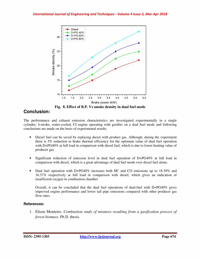
Smoke density:
The cause of smoke is incomplete combustion which may be due to incorrect air-fuel ratio or may
be due to improper mixing of fuel with air. As shown in Fig. 8, significant difference is observed between
smoke density of various fuels at noload and full load, but the change was very insignificant at low load
of the engine. In dual fuel mode of operation, the smoke density is observed to be higher than that of the
DF for all combination of PG. In diesel operation, the smoke density attained a maximum value of 25%
where as it is found to be 32% in dual fuel mode for D+PG80% at full load.
International Journal of Engineering and Techniques - Volume 4 Issue 2, Mar-Apr 2018
ISSN: 2395-1303 http://www.ijetjournal.org Page 674
Fig. 8. Effect of B.P. Vs smoke density in dual fuel mode
Conclusion: The performance and exhaust emission characteristics are investigated experimentally in a single
cylinder; 4-stroke, water-cooled, CI engine operating with gasifier on a dual fuel mode and following
conclusions are made on the basis of experimental results.
• Diesel fuel can be saved by replacing diesel with product gas. Although, during the experiment
there is 5% reduction in brake thermal efficiency for the optimum value of dual fuel operation
with D+PG40% at full load in comparison with diesel fuel, which is due to lower heating value of
producer gas.
• Significant reduction of emission level in dual fuel operation of D+PG40% at full load in
comparison with diesel, which is a great advantage of dual fuel mode over diesel fuel alone.
• Dual fuel operation with D+PG40% increases both HC and CO emissions up to 18.39% and
16.37% respectively at full load in comparison with diesel, which gives an indication of
insufficient oxygen in combustion chamber
.
Overall, it can be concluded that the dual fuel operations of dual-fuel with D+PG40% gives
improved engine performance and lower tail pipe emissions compared with other producer gas
flow rates.
References:
1. Eliseu Monteiro. Combustion study of mixtures resulting from a gasification process of
forest biomass. Ph.D. thesis.

International Journal of Engineering and Techniques - Volume 4 Issue 2, Mar-Apr 2018
ISSN: 2395-1303 http://www.ijetjournal.org Page 675
2. Hernandez J.J., Aranda- Almansa G. and Serrano C., Co-gasification of biomass wastes
and coal- coke blends in an entrained flow gasifier : An experimental study , Energy
Fuels , 24, 2479 -2488 (2010)
3. Salim Ali, Sunil Upadhyay, Devesh Kumar., Experimental Evaluation Of Performance
Variables And Emissions For Producer Gas–Diesel Engine. International Journal For
Technological Research In Engineering Volume 2, Issue 12, pg. 3122-3125
4. Biomass Conversion Technologies, Renewable Energy World, p. 46. (2006)
5. G.N.Tiwari and M.K.Ghosal, Fundamentals of Renewable Energy Sources: Basic
Principles and Applications.Narosa Publishing House, New Delhi, 2007.
6. Juan, J, Hernandez., Guadalupe Aranda-Almsnsa, Bula, A., 2010. Gasification of
biomass wastes in an entrained flow gasifier; effect of the particle size and the residence
time 91(6), pp. 681-692
7. Stassen, H.E.M., Knoef, H.A.M., 1993. Small scale gasification systems, The
Netherlands: Biomass Technology Group, University ofTwente.
8. McKendry, P. Energy production from biomass (part 3): gasification technologies.
Journal of Bioresource Technology 2002; 83: 55-63.
9. Bridgwater, A.V., Evans, G.D. An Assessment of Thermo chemical Conversion Systems
for Processing Biomass and Refuse. Harwell Laboratory, Energy Technology Support
Unit: ETSU B/T1/00207/REP; 1993.
10. Volli, V., Singh, R.K., 2012. Production of bio-oil from de-oiled cakes by thermal
pyrolysis, NIT Rourkela, India.
11. Lin C.L.,Wey M.L. and You S.D.,The effect of particle size distribution on minimum
fluidization velocity at high temperature, power technol.,126,297-301(2002)
12. Roy, M.M., Tomita, E., Kawahara, N., Harad, Y., Sakane, A., 2009. Performance and
emission comparison of a supercharged dual-fuel engine fueled by producer gases with
varying hydrogen content.
13. Das, D.K., Dash, S.P., Ghosal, M.K., 2011. Performance Study of a Diesel Engine by
using producer gas from Selected Agricultural Residues on Dual-Fuel Mode of Diesel-
cum-Producer gas.
14. Deshmukh, Samir J., Bhuyar, Lalit B., Thakre, Shashank B., 2008. Investigation on
Performance and Emission Characteristics of CI Engine Fuelled with Producer Gas and
Esters of Hingan (Balanites) Oil in Dual Fuel Mode.
15. Hassan, S., MohdNor, F., Zainal, Z.A., Miskam, M.A., 2011. Performance and emission
characteristics of supercharged Biomass producer gas-diesel dual fuel engine.
16. Mathur, M.L., Sharma, R.P., 2006. Internal combustion engine, Dhanpatrai publication,
p. 738.
17. Singh, R.N., Singh, S.P., Pathak, B.S., 2007.”Investigations on operation of CI engine
using producer gas and rice bran oil in mixed fuel mode.” Renewable Energy 32, pp.
1565-1580.

International Journal of Engineering and Techniques - Volume 4 Issue 2, Mar-Apr 2018
ISSN: 2395-1303 http://www.ijetjournal.org Page 676
18. Singh, R.N., Singh, S.P., Pathak, B.S., 2007. “Investigation on operation of CI engine
using producer gas and rice bran oil in mixed fuel mode”. Renewable Energy 32, pp.
1565-1580.


