THERMAL CAMERA Model 1950 - Get Electrical Testers · MAINTENANCE ... Thermal Imaging IR Camera...
44
Model 1950 ENGLISH User Manual THERMAL CAMERA
Transcript of THERMAL CAMERA Model 1950 - Get Electrical Testers · MAINTENANCE ... Thermal Imaging IR Camera...
Model 1950
ENGLISH User Manual
THERMAL CAMERA

2
CONTENTS
INTRODUCTION ................................................................................................................................................ 5 Receiving Your Shipment .............................................................................................................................. 5 Ordering Information ...................................................................................................................................... 5
1. GETTING STARTED ...................................................................................................................................... 6 1.1. Safety Precautions ................................................................................................................................. 6 1.2. Battery Installation .................................................................................................................................. 6
1.2.1. Battery Management ...................................................................................................................... 6 1.3. Micro SD Memory Card Installation ........................................................................................................ 7 1.4. Camera Display ...................................................................................................................................... 7
1.4.1. Main Screen ................................................................................................................................... 7 1.5. Configuring the Camera .......................................................................................................................10
1.5.1. Language ...................................................................................................................................... 11 1.5.2. Date and Time ..............................................................................................................................12 1.5.3. Units of Measure (Temperature and Distance) ............................................................................12 1.5.4. Trigger Function ............................................................................................................................12 1.5.5. Automatic Camera Shutdown Time ..............................................................................................13 1.5.6. Screen Brightness ........................................................................................................................13 1.5.7. Image Storage Directory ..............................................................................................................13 1.5.8. Color Palettes ...............................................................................................................................14
2. BASIC OPERATION.....................................................................................................................................15 2.1. Measurement Cursor ............................................................................................................................15
2.1.1. Estimating Measurements Without a Cursor ................................................................................15 2.1.2. Locating Hot and Cold Spots in an Image (MinMax) ....................................................................15 2.1.3. Measuring Temperature at a Point in the Image (Point) ...............................................................16 2.1.4. Measuring Temperatures of a Zone in the Image (Square) .........................................................16 2.1.5. Displaying the Temperature Profile of a Line in the Image (Profile) .............................................16 2.1.6. Displaying Points at the Same Temperature in an Image (Isotherm) ...........................................16
2.2. Freezing Palette Colors ........................................................................................................................16 3. ADVANCED OPERATION WITH MORE PRECISE MEASUREMENTS .....................................................17
3.1. Best Practices .......................................................................................................................................17 3.2. Compensating for Influencing Parameters ...........................................................................................17
3.2.1. Default Compensation Settings ....................................................................................................17 3.2.2. Custom Compensation Settings ...................................................................................................18
3.3. Tripod ....................................................................................................................................................18 4. SAVING AND RECALLING IMAGES ..........................................................................................................19
4.1. Image Files ...........................................................................................................................................19 4.1.1. Naming Conventions ....................................................................................................................19 4.1.2. Directories ....................................................................................................................................19
4.2. Saving an Image ...................................................................................................................................19 4.3. Vocal Message .....................................................................................................................................20
4.3.1. Creating a Vocal Message ...........................................................................................................20 4.3.2. Changing the Vocal Message for an Existing Image ....................................................................20 4.3.3. Playing Back a Vocal Message ....................................................................................................21
4.4. Recalling an Image ...............................................................................................................................21 4.4.1 Derived Files from Recalled Images .............................................................................................22
4.5. Deleting an Image ................................................................................................................................22 4.6. Downloading Images to a Computer ....................................................................................................22
4.6.1. Downloading Directly from the Micro SD Memory Card ...............................................................22 4.6.2. Via USB Cable ..............................................................................................................................23
4.7. CAmReport Image Analysis and Report Generation ............................................................................23 5. SETUP FILES AND RECALLING USER CONFIGURATIONS ...................................................................24
5.1. Creating a Setup File ............................................................................................................................24 5.2. Recalling a Setup File ...........................................................................................................................24 5.3. Deleting a Setup File ............................................................................................................................24 5.4. Restoring Original Default Settings ......................................................................................................25
3
6. BLUETOOTH ................................................................................................................................................26 6.1. Bluetooth Activation/Deactivation .........................................................................................................26
6.1.1. Activating Bluetooth ......................................................................................................................26 6.1.2. Deactivating Bluetooth..................................................................................................................26
6.2. Headset ................................................................................................................................................26 6.2.1. Headset Connection .....................................................................................................................26 6.2.2. Changing Headsets ......................................................................................................................27 6.2.3. Headset Disconnection ................................................................................................................27
6.3. Measurement Devices ..........................................................................................................................27 6.3.1. Peripheral Connection ..................................................................................................................27 6.3.2. Replacing Devices ........................................................................................................................28 6.3.3. Device Polling Period ...................................................................................................................28 6.3.4. Device Measurements Display .....................................................................................................28 6.3.5. Using a Measurement to Compensate for Environmental Factors ..............................................30
7. FIRMWARE UPDATES ................................................................................................................................31 8. TROUBLESHOOTING .................................................................................................................................32
8.1. IR Image is a Single Solid Color ...........................................................................................................32 8.1.1. Color Palette Frozen.....................................................................................................................32 8.1.2. Inconsistent "User" Influencing Parameters .................................................................................32
8.2. Contrast of IR Image is Incorrect ..........................................................................................................32 8.3. Unable to Save Displayed Image .........................................................................................................32 8.4. Slow Opening of Files ...........................................................................................................................32 8.5. Headset Cannot Connect to Camera ...................................................................................................32 8.6. Bluetooth Device Cannot Connect to Camera .....................................................................................32 8.7. Bluetooth Measurements Not Displayed/Refreshed ............................................................................33
9. MAINTENANCE ...........................................................................................................................................34 9.1. Camera Cleaning ..................................................................................................................................34 9.2. Infrared Optics Cleaning .......................................................................................................................34
APPENDIX A: MENU TREE.............................................................................................................................35 APPENDIX B: EMISSIVITY TABLE .................................................................................................................38 APPENDIX C: TECHNICAL SPECIFICATIONS ..............................................................................................39 REPAIR AND CALIBRATION ..........................................................................................................................40 TECHNICAL AND SALES ASSISTANCE .......................................................................................................40 LIMITED WARRANTY ......................................................................................................................................40
Warranty Repairs .........................................................................................................................................41
4
INTRODUCTION
Do not aim the camera at the sun or other sources of powerful thermal radiation.
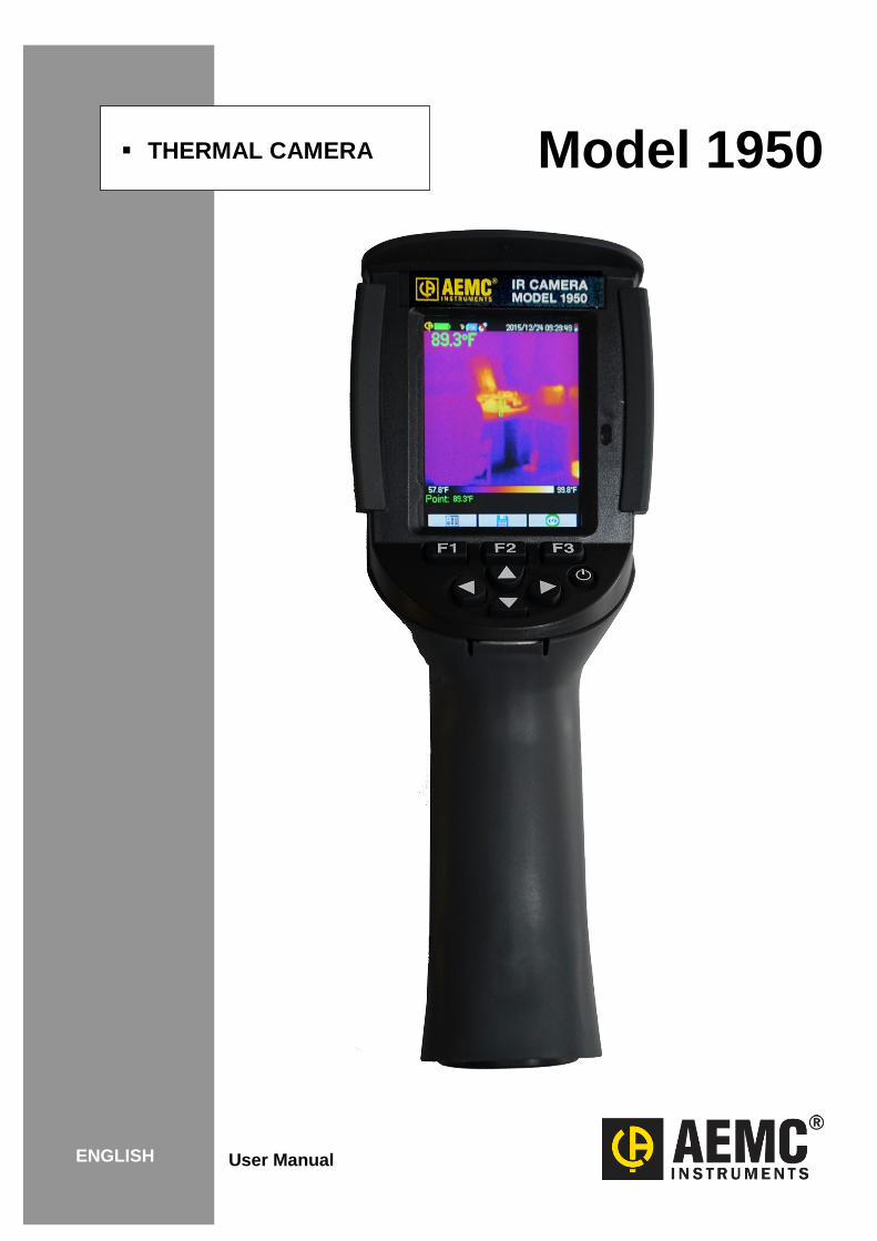
Thank you for purchasing the Thermal Imaging IR Camera Model 1950.
For best results with your camera: Read these operating instructions carefully. Comply with the precautions for use.
Symbols:
WARNING: Risk of damage to the instrument.
Information or useful tip.
The CE marking indicates compliance with the European "Low Voltage" and "Electromagnetic Compatibility" directives (2006/95/EC and 2004/108/EC).
In the European Union, this product is subject to selective collection and recycling at end-of-life as waste electrical and electronic equipment under directive 2002/96/EC (WEEE). Neither this equipment nor its batteries are to be treated as ordinary household waste. Spent batteries must be taken to an appropriate collection facility for recycling.
This product is designed to allow recovery and recycling of most of its constituents.
Receiving Your Shipment Upon receiving your shipment, make sure that the contents are consistent with the packing list. Notify your distributor of any missing items. If the equipment appears to be damaged, file a claim immediately with the carrier and notify your distributor at once, giving a detailed description of any damage. Save the damaged packing container to substantiate your claim.
Ordering Information Thermal Imaging IR Camera Model 1950…………………………………………………………...... Cat. #2121.40 Includes carrying case, eUSB cable, four NiMh rechargeable batteries, micro SD card with adaptor, Bluetooth headset, quick start guide, and a USB thumb drive containing the user manual, CAmReport software, and software manual.
Replacement Parts:
Case – Carrying Case with Foam Insert ..................................................................................... …Cat. #2121.60
Cable – USB (Type A to 5-pin Mini-B) ............................................................................................ Cat. #2126.49
The rechargeable batteries supplied with the camera can be charged with any commercially available AA charger.
5
1. GETTING STARTED
1.1. Safety Precautions Never aim the camera at the sun or other strong source of thermal radiation. This can impair
camera operation and/or damage its infrared sensor. To avoid accidental exposure, close the lens flapwhen the camera is not in use.
Avoid exposure to dust with the lens flap open. Dust on the lens can absorb thermal flux and causeartificial diffusion. It can also degrade image sharpness. To clean the lens, refer to § 9.2.
Do not touch the lens with your fingers. Acids from human skin can damage the lens and its coatings.
Avoid jolting or dropping the camera.
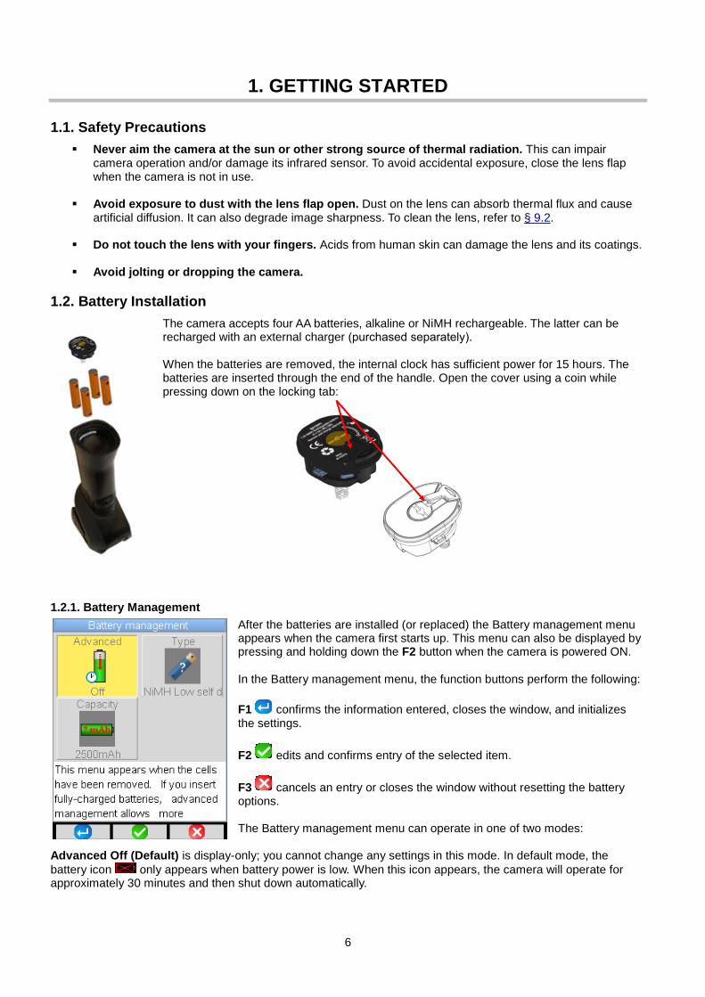
1.2. Battery Installation The camera accepts four AA batteries, alkaline or NiMH rechargeable. The latter can be recharged with an external charger (purchased separately).
When the batteries are removed, the internal clock has sufficient power for 15 hours. The batteries are inserted through the end of the handle. Open the cover using a coin while pressing down on the locking tab:
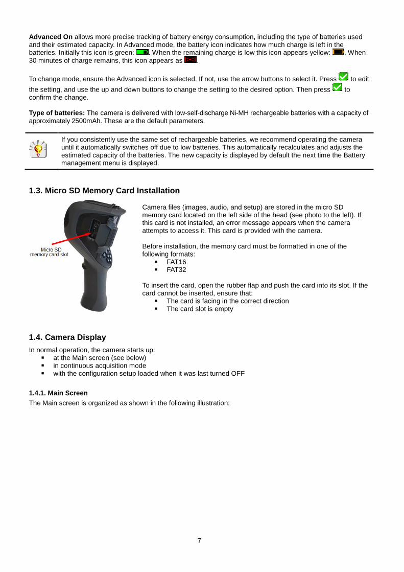
1.2.1. Battery Management After the batteries are installed (or replaced) the Battery management menu appears when the camera first starts up. This menu can also be displayed by pressing and holding down the F2 button when the camera is powered ON.
In the Battery management menu, the function buttons perform the following:
F1 confirms the information entered, closes the window, and initializes the settings.
F2 edits and confirms entry of the selected item.
F3 cancels an entry or closes the window without resetting the battery options.
The Battery management menu can operate in one of two modes:
Advanced Off (Default) is display-only; you cannot change any settings in this mode. In default mode, the battery icon only appears when battery power is low. When this icon appears, the camera will operate for approximately 30 minutes and then shut down automatically.
6
Advanced On allows more precise tracking of battery energy consumption, including the type of batteries used and their estimated capacity. In Advanced mode, the battery icon indicates how much charge is left in the batteries. Initially this icon is green: . When the remaining charge is low this icon appears yellow: . When 30 minutes of charge remains, this icon appears as . To change mode, ensure the Advanced icon is selected. If not, use the arrow buttons to select it. Press to edit the setting, and use the up and down buttons to change the setting to the desired option. Then press to confirm the change. Type of batteries: The camera is delivered with low-self-discharge Ni-MH rechargeable batteries with a capacity of approximately 2500mAh. These are the default parameters.
If you consistently use the same set of rechargeable batteries, we recommend operating the camera until it automatically switches off due to low batteries. This automatically recalculates and adjusts the estimated capacity of the batteries. The new capacity is displayed by default the next time the Battery management menu is displayed.
1.3. Micro SD Memory Card Installation
Camera files (images, audio, and setup) are stored in the micro SD memory card located on the left side of the head (see photo to the left). If this card is not installed, an error message appears when the camera attempts to access it. This card is provided with the camera. Before installation, the memory card must be formatted in one of the following formats:
FAT16 FAT32
To insert the card, open the rubber flap and push the card into its slot. If the card cannot be inserted, ensure that:
The card is facing in the correct direction The card slot is empty
1.4. Camera Display In normal operation, the camera starts up:
at the Main screen (see below) in continuous acquisition mode with the configuration setup loaded when it was last turned OFF
1.4.1. Main Screen The Main screen is organized as shown in the following illustration:
7
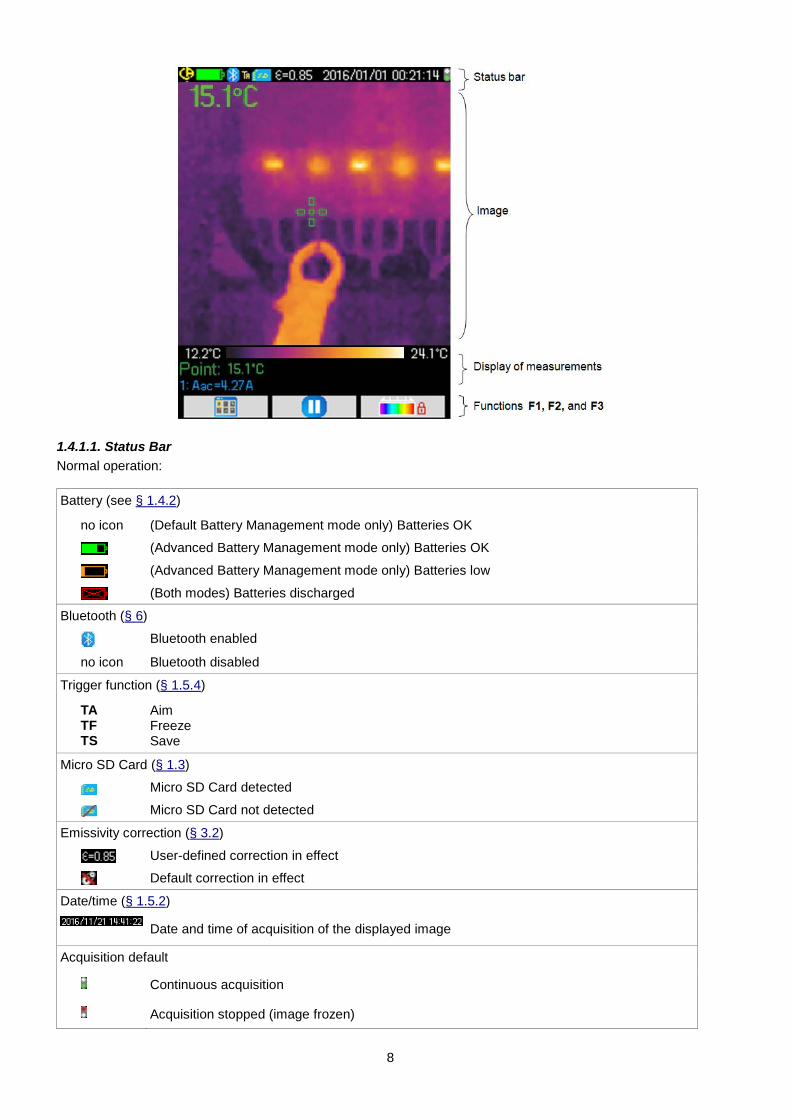
1.4.1.1. Status Bar Normal operation: Battery (see § 1.4.2)
no icon (Default Battery Management mode only) Batteries OK
(Advanced Battery Management mode only) Batteries OK
(Advanced Battery Management mode only) Batteries low
(Both modes) Batteries discharged
Bluetooth (§ 6)
Bluetooth enabled
no icon Bluetooth disabled
Trigger function (§ 1.5.4)
TA TF TS
Aim Freeze Save
Micro SD Card (§ 1.3)
Micro SD Card detected
Micro SD Card not detected
Emissivity correction (§ 3.2)
User-defined correction in effect
Default correction in effect
Date/time (§ 1.5.2)
Date and time of acquisition of the displayed image
Acquisition default
Continuous acquisition
Acquisition stopped (image frozen)
8
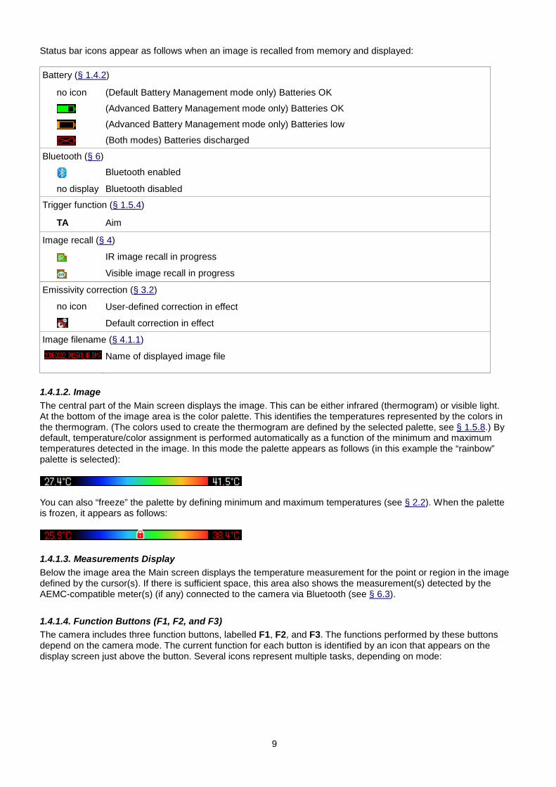
Status bar icons appear as follows when an image is recalled from memory and displayed: Battery (§ 1.4.2)
no icon (Default Battery Management mode only) Batteries OK
(Advanced Battery Management mode only) Batteries OK
(Advanced Battery Management mode only) Batteries low
(Both modes) Batteries discharged
Bluetooth (§ 6)
Bluetooth enabled
no display Bluetooth disabled
Trigger function (§ 1.5.4)
TA Aim
Image recall (§ 4)
IR image recall in progress
Visible image recall in progress
Emissivity correction (§ 3.2)
no icon User-defined correction in effect
Default correction in effect
Image filename (§ 4.1.1)
Name of displayed image file
1.4.1.2. Image The central part of the Main screen displays the image. This can be either infrared (thermogram) or visible light. At the bottom of the image area is the color palette. This identifies the temperatures represented by the colors in the thermogram. (The colors used to create the thermogram are defined by the selected palette, see § 1.5.8.) By default, temperature/color assignment is performed automatically as a function of the minimum and maximum temperatures detected in the image. In this mode the palette appears as follows (in this example the “rainbow” palette is selected):
You can also “freeze” the palette by defining minimum and maximum temperatures (see § 2.2). When the palette is frozen, it appears as follows:
1.4.1.3. Measurements Display Below the image area the Main screen displays the temperature measurement for the point or region in the image defined by the cursor(s). If there is sufficient space, this area also shows the measurement(s) detected by the AEMC-compatible meter(s) (if any) connected to the camera via Bluetooth (see § 6.3).
1.4.1.4. Function Buttons (F1, F2, and F3) The camera includes three function buttons, labelled F1, F2, and F3. The functions performed by these buttons depend on the camera mode. The current function for each button is identified by an icon that appears on the display screen just above the button. Several icons represent multiple tasks, depending on mode:
9
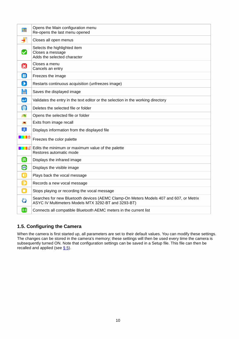
Opens the Main configuration menu Re-opens the last menu opened
Closes all open menus
Selects the highlighted item Closes a message Adds the selected character
Closes a menu Cancels an entry
Freezes the image
Restarts continuous acquisition (unfreezes image)
Saves the displayed image
Validates the entry in the text editor or the selection in the working directory
Deletes the selected file or folder
Opens the selected file or folder
Exits from image recall
Displays information from the displayed file
Freezes the color palette
Edits the minimum or maximum value of the palette Restores automatic mode
Displays the infrared image
Displays the visible image
Plays back the vocal message
Records a new vocal message
Stops playing or recording the vocal message
Searches for new Bluetooth devices (AEMC Clamp-On Meters Models 407 and 607, or Metrix ASYC IV Multimeters Models MTX 3292-BT and 3293-BT)
Connects all compatible Bluetooth AEMC meters in the current list
1.5. Configuring the Camera When the camera is first started up, all parameters are set to their default values. You can modify these settings. The changes can be stored in the camera’s memory; these settings will then be used every time the camera is subsequently turned ON. Note that configuration settings can be saved in a Setup file. This file can then be recalled and applied (see § 5).
10
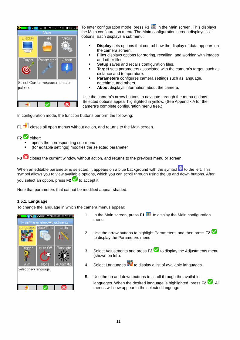
To enter configuration mode, press F1 in the Main screen. This displays the Main configuration menu. The Main configuration screen displays six options. Each displays a submenu:
Display sets options that control how the display of data appears on the camera screen.
Files displays options for storing, recalling, and working with images and other files.
Setup saves and recalls configuration files. Target sets parameters associated with the camera’s target, such as
distance and temperature. Parameters configures camera settings such as language,
date/time, and others. About displays information about the camera.
Use the camera’s arrow buttons to navigate through the menu options. Selected options appear highlighted in yellow. (See Appendix A for the camera’s complete configuration menu tree.)
In configuration mode, the function buttons perform the following:
F1 closes all open menus without action, and returns to the Main screen. F2 either:
opens the corresponding sub-menu (for editable settings) modifies the selected parameter
F3 closes the current window without action, and returns to the previous menu or screen. When an editable parameter is selected, it appears on a blue background with the symbol to the left. This symbol allows you to view available options, which you can scroll through using the up and down buttons. After you select an option, press F2 to accept it. Note that parameters that cannot be modified appear shaded.
1.5.1. Language To change the language in which the camera menus appear:
1. In the Main screen, press F1 to display the Main configuration menu.
2. Use the arrow buttons to highlight Parameters, and then press F2 to display the Parameters menu.
3. Select Adjustments and press F2 to display the Adjustments menu (shown on left).
4. Select Languages to display a list of available languages.
5. Use the up and down buttons to scroll through the available languages. When the desired language is highlighted, press F2 . All menus will now appear in the selected language.
11
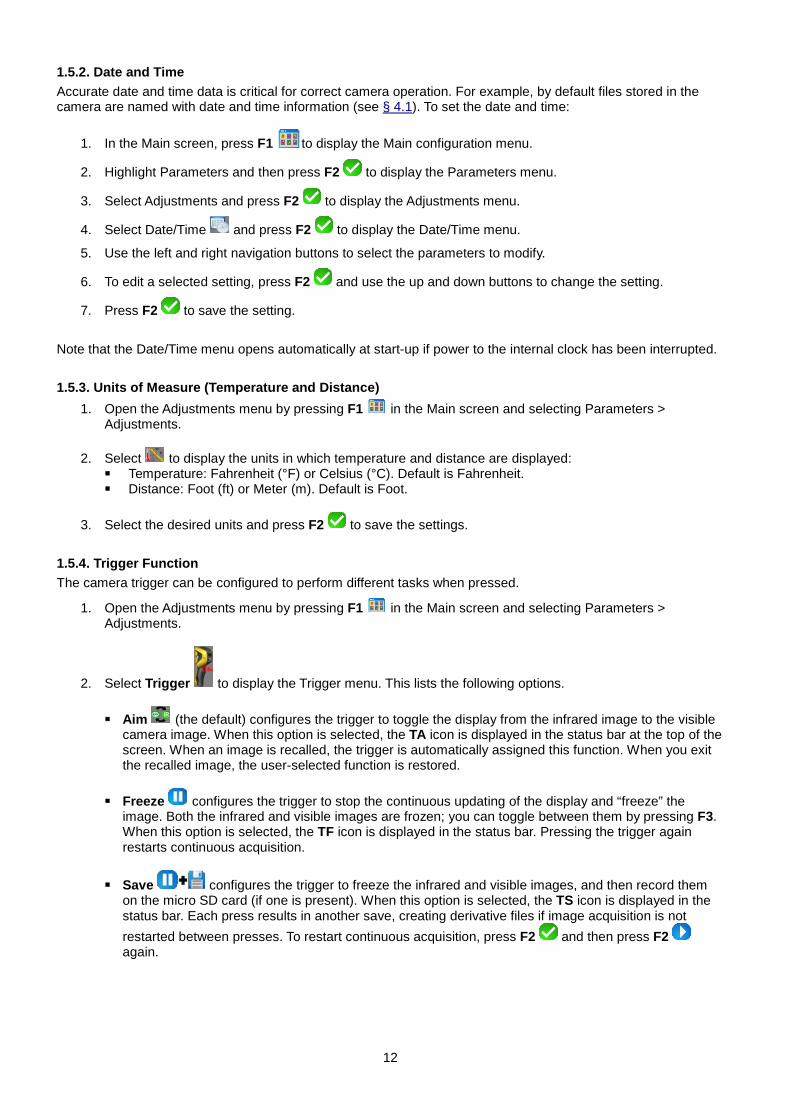
1.5.2. Date and Time Accurate date and time data is critical for correct camera operation. For example, by default files stored in the camera are named with date and time information (see § 4.1). To set the date and time:
1. In the Main screen, press F1 to display the Main configuration menu.
2. Highlight Parameters and then press F2 to display the Parameters menu.
3. Select Adjustments and press F2 to display the Adjustments menu.
4. Select Date/Time and press F2 to display the Date/Time menu.
5. Use the left and right navigation buttons to select the parameters to modify.
6. To edit a selected setting, press F2 and use the up and down buttons to change the setting.
7. Press F2 to save the setting.
Note that the Date/Time menu opens automatically at start-up if power to the internal clock has been interrupted. 1.5.3. Units of Measure (Temperature and Distance)
1. Open the Adjustments menu by pressing F1 in the Main screen and selecting Parameters > Adjustments.
2. Select to display the units in which temperature and distance are displayed: Temperature: Fahrenheit (°F) or Celsius (°C). Default is Fahrenheit. Distance: Foot (ft) or Meter (m). Default is Foot.
3. Select the desired units and press F2 to save the settings.
1.5.4. Trigger Function The camera trigger can be configured to perform different tasks when pressed.
1. Open the Adjustments menu by pressing F1 in the Main screen and selecting Parameters > Adjustments.
2. Select Trigger to display the Trigger menu. This lists the following options. Aim (the default) configures the trigger to toggle the display from the infrared image to the visible
camera image. When this option is selected, the TA icon is displayed in the status bar at the top of the screen. When an image is recalled, the trigger is automatically assigned this function. When you exit the recalled image, the user-selected function is restored.
Freeze configures the trigger to stop the continuous updating of the display and “freeze” the image. Both the infrared and visible images are frozen; you can toggle between them by pressing F3. When this option is selected, the TF icon is displayed in the status bar. Pressing the trigger again restarts continuous acquisition.
Save configures the trigger to freeze the infrared and visible images, and then record them on the micro SD card (if one is present). When this option is selected, the TS icon is displayed in the status bar. Each press results in another save, creating derivative files if image acquisition is not restarted between presses. To restart continuous acquisition, press F2 and then press F2 again.
12
1.5.5. Automatic Camera Shutdown Time To save battery power, the camera automatically turns OFF after a period of inactivity. The duration of this period can be set to between 15 (default) and 60 minutes. This feature can also be disabled. To change this setting:
1. Open the Adjustments menu by pressing F1 in the Main screen and selecting Parameters > Adjustments.
2. Select to display the shutdown time setting.
3. Use the up and down buttons to change settings. You can also select None to disable automatic shutdown. When None is selected, the camera turns off only when battery power is too low to continue operation.
4. When the desired setting is displayed, press F2 .
1.5.6. Screen Brightness You can adjust the screen brightness level to ensure good visibility in varying lighting conditions. By default, the camera is configured in Automatic mode: a brightness sensor adjusts the lighting level at all times. To change this:
1. Open the Adjustments menu by pressing F1 in the Main screen and selecting Parameters > Adjustments.
2. Select to display the screen brightness setting. Use the up and down buttons to change this setting. Options are Automatic (the camera automatically adjusts the screen brightness), or a percentage of full screen brightness (15%, 25%, 50%, 75%, or 100%).
3. When the desired setting is displayed, press F2 to select it.
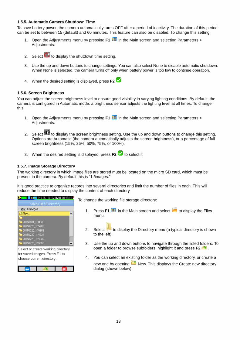
1.5.7. Image Storage Directory The working directory in which image files are stored must be located on the micro SD card, which must be present in the camera. By default this is "1:/images." It is good practice to organize records into several directories and limit the number of files in each. This will reduce the time needed to display the content of each directory.
To change the working file storage directory:
1. Press F1 in the Main screen and select to display the Files menu.
2. Select to display the Directory menu (a typical directory is shown to the left).
3. Use the up and down buttons to navigate through the listed folders. To open a folder to browse subfolders, highlight it and press F2 .
4. You can select an existing folder as the working directory, or create a new one by opening New. This displays the Create new directory dialog (shown below):
13
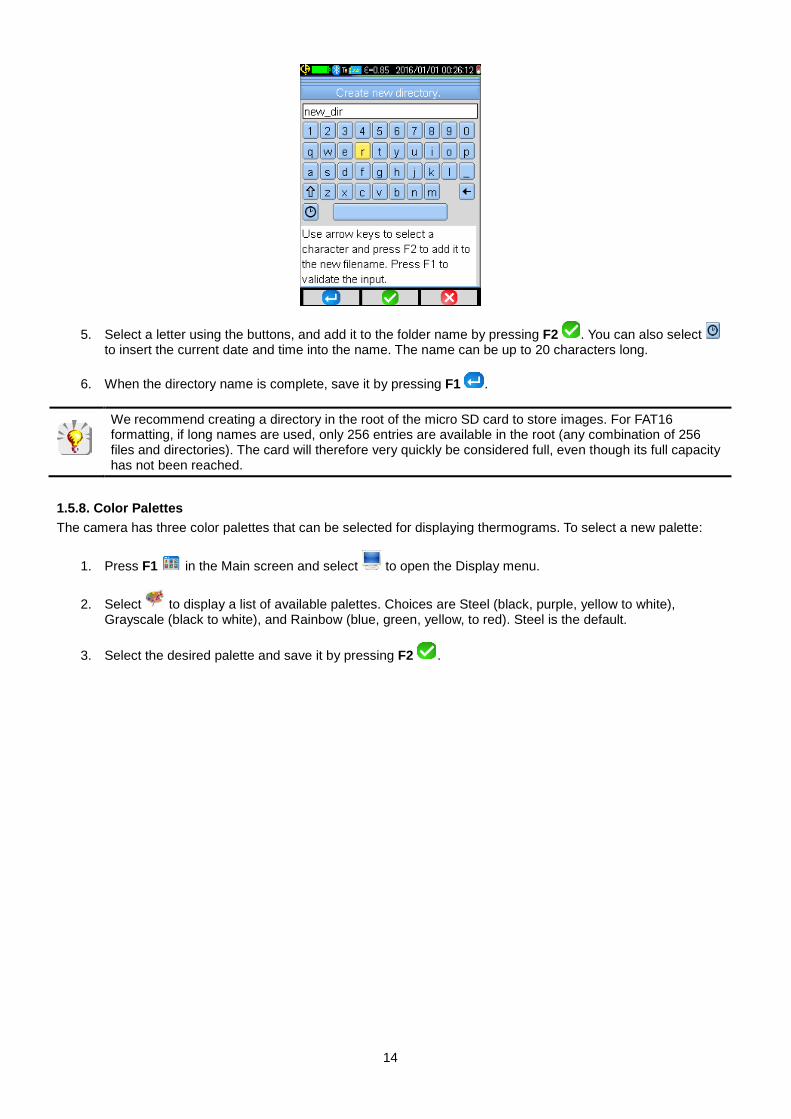
5. Select a letter using the buttons, and add it to the folder name by pressing F2 . You can also selectto insert the current date and time into the name. The name can be up to 20 characters long.
6. When the directory name is complete, save it by pressing F1 .
We recommend creating a directory in the root of the micro SD card to store images. For FAT16 formatting, if long names are used, only 256 entries are available in the root (any combination of 256 files and directories). The card will therefore very quickly be considered full, even though its full capacity has not been reached.
1.5.8. Color Palettes The camera has three color palettes that can be selected for displaying thermograms. To select a new palette:
1. Press F1 in the Main screen and select to open the Display menu.
2. Select to display a list of available palettes. Choices are Steel (black, purple, yellow to white), Grayscale (black to white), and Rainbow (blue, green, yellow, to red). Steel is the default.
3. Select the desired palette and save it by pressing F2 .
14
2. BASIC OPERATION
To display a thermal image (thermogram), ensure the camera’s lens flap is in the up position, uncovering the IR lens. Then turn ON the camera and point it at the target object. The thermogram appears in the camera’s main screen (see § 1.4.1). When default settings are in effect, to stop data acquisition and freeze the image on the display, press F2 . When the image is frozen, the F2 button function becomes . Press this button to unfreeze the image and resume data acquisition.
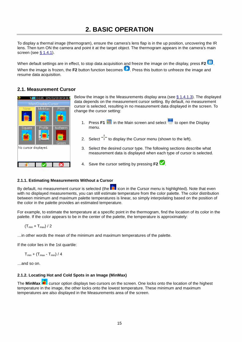
2.1. Measurement Cursor Below the image is the Measurements display area (see § 1.4.1.3). The displayed data depends on the measurement cursor setting. By default, no measurement cursor is selected, resulting in no measurement data displayed in the screen. To change the cursor setting:
1. Press F1 in the Main screen and select to open the Display menu.
2. Select to display the Cursor menu (shown to the left).
3. Select the desired cursor type. The following sections describe what measurement data is displayed when each type of cursor is selected.
4. Save the cursor setting by pressing F2 .
2.1.1. Estimating Measurements Without a Cursor
By default, no measurement cursor is selected (the icon in the Cursor menu is highlighted). Note that even with no displayed measurements, you can still estimate temperature from the color palette. The color distribution between minimum and maximum palette temperatures is linear, so simply interpolating based on the position of the color in the palette provides an estimated temperature. For example, to estimate the temperature at a specific point in the thermogram, find the location of its color in the palette. If the color appears to be in the center of the palette, the temperature is approximately:
(Tmin + Tmax) / 2 …in other words the mean of the minimum and maximum temperatures of the palette. If the color lies in the 1st quartile:
Tmin + (Tmax - Tmin) / 4 …and so on.
2.1.2. Locating Hot and Cold Spots in an Image (MinMax)
The MinMax cursor option displays two cursors on the screen. One locks onto the location of the highest temperature in the image, the other locks onto the lowest temperature. These minimum and maximum temperatures are also displayed in the Measurements area of the screen.
15
2.1.3. Measuring Temperature at a Point in the Image (Point)
The Point cursor option displays a single cursor along with the temperature at the current cursor location. You can move the cursor with the up, down, left, and right directional buttons to display the temperature at different points in the thermogram.
2.1.4. Measuring Temperatures of a Zone in the Image (Square)
The Square cursor option displays a square on the screen, with the maximum and minimum temperatures within the square also displayed. Use the directional buttons to move the square on the screen. You can also resize the square by pressing the up and left buttons simultaneously to reduce the size, or down and right to increase the size.
2.1.5. Displaying the Temperature Profile of a Line in the Image (Profile)
The Profile cursor option displays the temperature profile of a user-selectable horizontal line defined by the cursor on the screen. The profile is displayed as a graph in the lower part of the screen. This cursor also identifies a point on this line and indicates its temperature.
2.1.6. Displaying Points at the Same Temperature in an Image (Isotherm)
The Isotherm cursor option displays all points that fall within the same temperature range in the same color within a certain tolerance. When you choose this icon, you are prompted to choose the color (green, red, or brown) to display the points. After you press F2 to save the color selection, the screen displays the thermogram. You are then prompted to enter the reference temperature (via the up and down buttons) and tolerance size (via the left and right buttons). Both the reference temperature and the temperature range (defined as ± the tolerance setting) are displayed at the bottom of the screen. In addition, the palette graphically displays the temperature range. All points in the image whose temperature falls within this defined range are displayed in the selected color.
2.2. Freezing Palette Colors By default, thermogram colors are calculated for each image (based on the highest and lowest temperatures in the image) and assigned accordingly. As a result, the same color may not represent the same temperature in different images. You can “freeze” the palette to ensure each color represents the same temperature in all images. When the palette is frozen, a red padlock appears on the palette. The minimum and maximum values are also displayed in red. To enter frozen palette mode, do either of the following:
Press F2 or F3 when this button’s function is displayed as . Press F1 in the Main screen and select Parameters. Then select the icon and choose the
Manual option. When you enter frozen palette mode, the minimum temperature displayed on the left end of the palette enters edit mode for 2 seconds (highlighted in blue with the symbol) so you can increase or decrease this value using the up and down buttons. To modify the maximum temperature setting, press the right button when the minimum setting is in edit mode. This highlights the maximum value, which remains in edit mode for 2 seconds. Use the up and down buttons to increase or decrease this value. If you do not press a button within 2 seconds, edit mode is disabled. To re-edit these values, press F3 when the icon is displayed (or select in the Parameters menu) to enable edit mode for the minimum value. To exit frozen palette mode, do one of the following:
Not in edit mode: press F2 or F3 twice while the icon is displayed. Edit mode: Press F2 or F3 once while the icon is displayed. Open the Parameters menu and select . Then select Automatic.
16
3. ADVANCED OPERATION WITH MORE PRECISE MEASUREMENTS
3.1. Best Practices Make the measurement in the central zone of the screen.
Aim straight on, not at an angle.
Measure targets that are as large as possible. Avoid point-like targets.
If the ambient temperature changes significantly, allow the camera to stabilize.
If batteries have warmed up during charging, wait for them to cool down to ambient before putting them back in the camera.
3.2. Compensating for Influencing Parameters Measurements can be influenced by:
emissivity of the target object
temperature of the environment
distance to the target
relative humidity of the air
Emissivity is the most crucial factor. This defines the efficiency with which a material radiates infrared energy. Different materials have different emissivity values. A perfect “blackbody” has an emissivity of 1.00 (the theoretical maximum), while a material that emits no infrared energy has an emissivity of 0.00. Black electrical tape has an emissivity of 0.95 and is suitable as a reference target. The higher the relative humidity and the greater the distance, the larger the effect relative humidity has on the measurement. The relative humidity, ambient temperature, and distance are likely to vary more significantly outdoors. The camera default settings may not be suitable for the present environmental factors, resulting in possible measurement errors. In these situations, we recommend adjusting the camera settings to compensate for these factors. These are set through the Target menu (see below).
Incorrect settings can produce results less accurate than results obtained with the default settings.
3.2.1. Default Compensation Settings
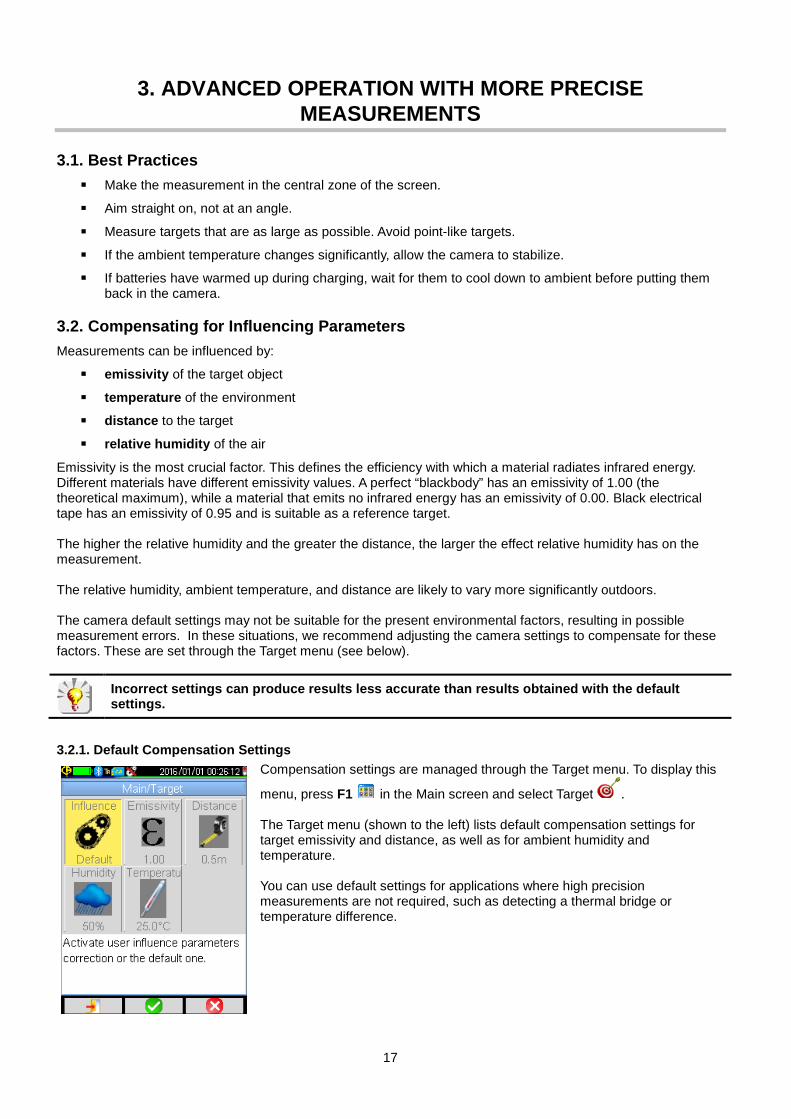
Compensation settings are managed through the Target menu. To display this
menu, press F1 in the Main screen and select Target . The Target menu (shown to the left) lists default compensation settings for target emissivity and distance, as well as for ambient humidity and temperature. You can use default settings for applications where high precision measurements are not required, such as detecting a thermal bridge or temperature difference.
17
3.2.2. Custom Compensation Settings Influencing parameters should be adjusted from their defaults when:
Environmental conditions are significantly different from default settings for emissivity, relative humidity, temperature, and distance
High measurement accuracy is required
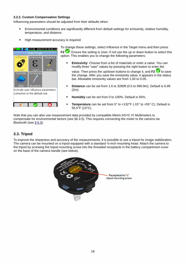
To change these settings, select Influence in the Target menu and then press F2 . Ensure the setting is User; if not use the up or down button to select this option. This enables you to change the following parameters:
Emissivity: Choose from a list of materials or enter a value. You can modify three “user” values by pressing the right button to enter the value. Then press the up/down buttons to change it, and F2 to save the change. After you save the emissivity value, it appears in the status bar. Allowable emissivity values are from 1.00 to 0.05.
Distance can be set from 1.6 to 3280ft (0.5 to 999.9m). Default is 6.6ft (2m).
Humidity can be set from 0 to 100%. Default is 55%.
Temperature can be set from 5° to +132°F (-15° to +55° C). Default is 55.5°F (13°C).
Note that you can also use measurement data provided by compatible Metrix ASYC IV Multimeters to compensate for environmental factors (see §6.3.5). This requires connecting the meter to the camera via Bluetooth (see § 6.3).
3.3. Tripod To improve the sharpness and accuracy of the measurements, it is possible to use a tripod for image stabilization. The camera can be mounted on a tripod equipped with a standard ¼-inch mounting head. Attach the camera to the tripod by screwing the tripod mounting screw into the threaded receptacle in the battery compartment cover on the base of the camera handle (see below).
18
4. SAVING AND RECALLING IMAGES
When the micro SD memory card is inserted into the camera (see § 1.3), you can store and later recall the displayed image and measurements.
4.1. Image Files 4.1.1. Naming Conventions The camera has two objective lenses, one for infrared images and the other for visible light images. When an image is saved, two files are created. The infrared image is saved using the filename convention:
yyyymmdd_hhmmss_IR.BMP …where “yyyymmdd_hhmmss” is the date and time the image was acquired. The visible image is saved using the same naming convention, but without the “IR” designation (yyyymmdd_hhmmss.BMP). This naming convention requires accurate date/time settings (see § 1.5.2). An audio file can also be included with the two images. This allows you to record a description and other information relevant to the images. This requires a Bluetooth headset connected to the camera (see § 6.2). This file is given the same name as the associated IR image, with the extension .WAV instead of .BMP (for example yyyymmdd_hhmmss_IR.WAV). After you save an image, you can create copies of it (with palette changes, additions of cursors, and so on) by:
Saving the same frozen image multiple times Recalling the original saved image from the camera’s memory and saving it again (see § 4.4.1)
These copies are called “derived” images. To differentiate derived image files (which all have the same date of acquisition) an index letter is added after the date (for instance 20141020_131254a_IR.BMP). When all letters from "a" to "z" have been used, the letter "z" is re-used and the existing file with this name is overwritten. Note that a visible image is not created for the derived file, since the visible image associated with the original file also applies to the derived file.
When erasing visible images other than through the camera's file manager, take care not to create “orphan” IR images for which no corresponding visible light image exists.
4.1.2. Directories Image files are saved in the working directory defined in the Directory menu (see § 1.5.7). The working directory must be located on the micro SD card installed in the camera. If the card is missing, an error message appears when you attempt to save an image.
4.2. Saving an Image You can save an image when a micro SD memory card is inserted into the camera. To save a new image file:
If the trigger function setting is Aim or Freeze (see § 1.5.4), you must first stop acquisition. If the trigger function is Aim, press F2 to freeze the image and then press F3 . If the trigger function is Freeze, press the trigger and then press F2 . In either case the displayed image is saved in the working directory.
If the trigger function is Save, each press freezes the image (if it is not already frozen) and saves it in memory.
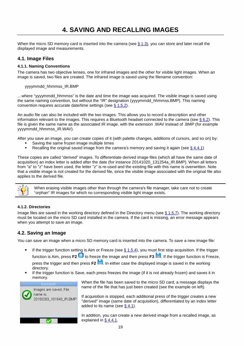
When the file has been saved to the micro SD card, a message displays the name of the file that has just been created (see the example on left). If acquisition is stopped, each additional press of the trigger creates a new "derived" image (same date of acquisition), differentiated by an index letter added to its name (see § 4.1). In addition, you can create a new derived image from a recalled image, as explained in § 4.4.1.
19
Depending on the situation, 1, 2, or 3 files are saved: 1 file is created when you save a derived image with no headset connected. The visible image associated with the derived image already exists, so only an IR file is created. 2 files are created when saving:
An original file with no headset attached (the IR image and its visible image). A derived image with a headset attached, and you create a voice recording (§ 4.3) for the derived image.
3 files are created when you save a new image with the headset attached, and you create a voice recording (IR image, visible image, and voice).
4.3. Vocal Message 4.3.1. Creating a Vocal Message
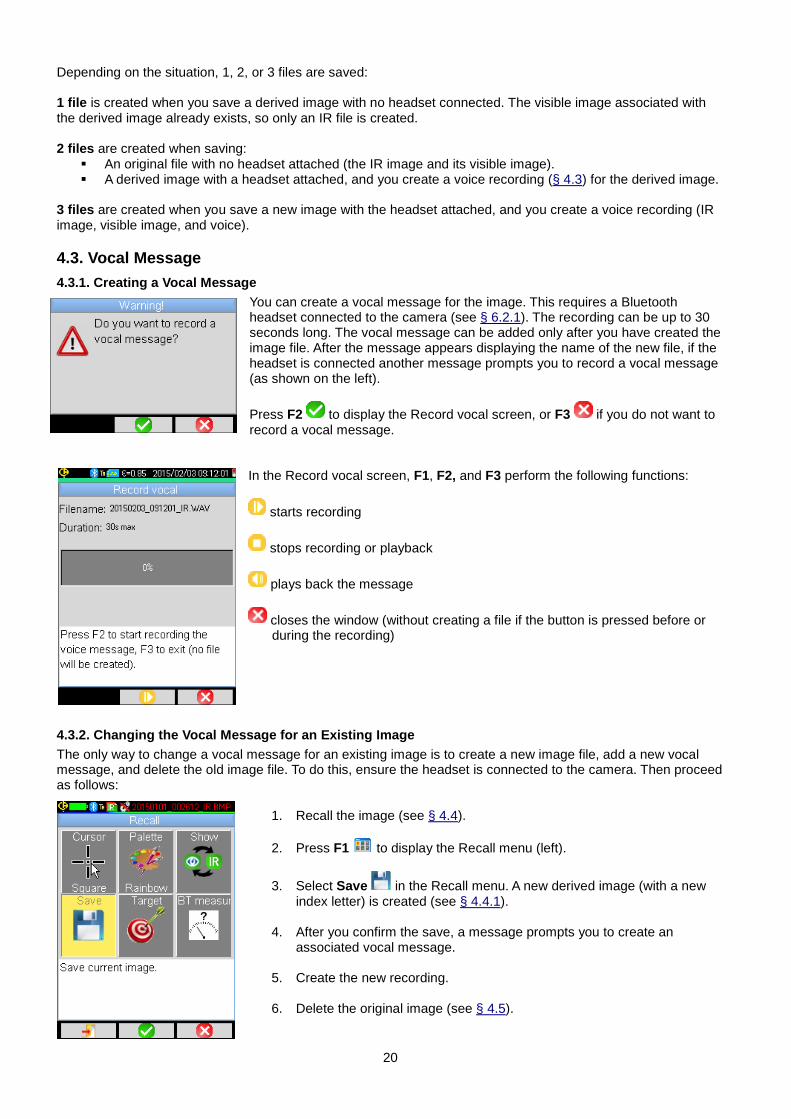
You can create a vocal message for the image. This requires a Bluetooth headset connected to the camera (see § 6.2.1). The recording can be up to 30 seconds long. The vocal message can be added only after you have created the image file. After the message appears displaying the name of the new file, if the headset is connected another message prompts you to record a vocal message (as shown on the left). Press F2 to display the Record vocal screen, or F3 if you do not want to record a vocal message.
In the Record vocal screen, F1, F2, and F3 perform the following functions:
starts recording
stops recording or playback
plays back the message
closes the window (without creating a file if the button is pressed before or during the recording)
4.3.2. Changing the Vocal Message for an Existing Image The only way to change a vocal message for an existing image is to create a new image file, add a new vocal message, and delete the old image file. To do this, ensure the headset is connected to the camera. Then proceed as follows:
1. Recall the image (see § 4.4).
2. Press F1 to display the Recall menu (left).
3. Select Save in the Recall menu. A new derived image (with a new
index letter) is created (see § 4.4.1).
4. After you confirm the save, a message prompts you to create an associated vocal message.
5. Create the new recording. 6. Delete the original image (see § 4.5).
20
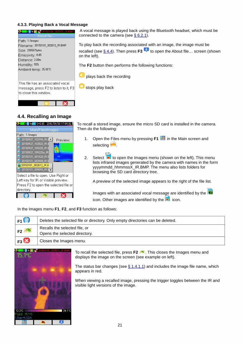
4.3.3. Playing Back a Vocal Message A vocal message is played back using the Bluetooth headset, which must be connected to the camera (see § 6.2.1). To play back the recording associated with an image, the image must be recalled (see § 4.4). Then press F3 to open the About file… screen (shown on the left). The F2 button then performs the following functions:
plays back the recording
stops play back
4.4. Recalling an Image To recall a stored image, ensure the micro SD card is installed in the camera. Then do the following:
1. Open the Files menu by pressing F1 in the Main screen and selecting .
2. Select to open the Images menu (shown on the left). This menu lists infrared images generated by the camera with names in the form yyyymmdd_hhmmssX_IR.BMP. The menu also lists folders for browsing the SD card directory tree. A preview of the selected image appears to the right of the file list.
Images with an associated vocal message are identified by the icon. Other images are identified by the icon.
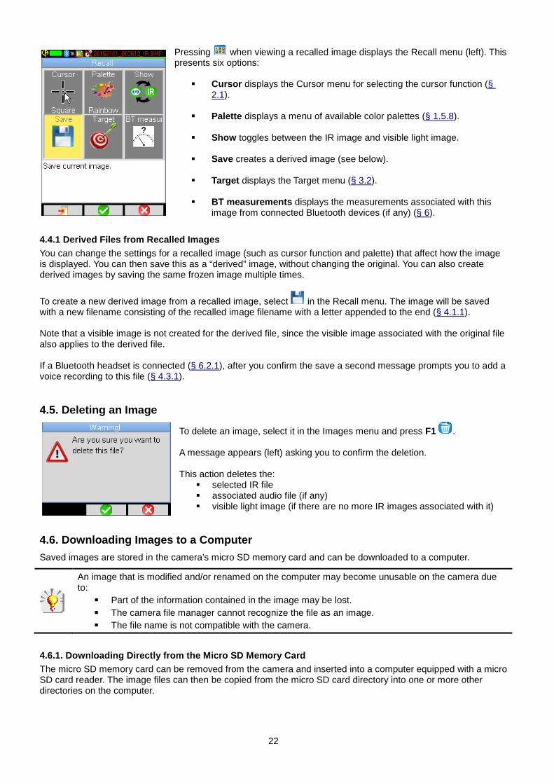
In the Images menu F1, F2, and F3 function as follows:
F1 Deletes the selected file or directory. Only empty directories can be deleted.
F2 Recalls the selected file, or Opens the selected directory.
F3 Closes the Images menu. To recall the selected file, press F2 . This closes the Images menu and displays the image on the screen (see example on left). The status bar changes (see § 1.4.1.1) and includes the image file name, which appears in red. When viewing a recalled image, pressing the trigger toggles between the IR and visible light versions of the image.
21
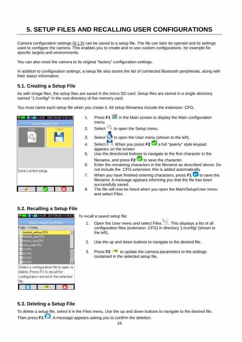
Pressing when viewing a recalled image displays the Recall menu (left). This presents six options:
Cursor displays the Cursor menu for selecting the cursor function (§ 2.1).
Palette displays a menu of available color palettes (§ 1.5.8).
Show toggles between the IR image and visible light image.
Save creates a derived image (see below).
Target displays the Target menu (§ 3.2).
BT measurements displays the measurements associated with this image from connected Bluetooth devices (if any) (§ 6).
4.4.1 Derived Files from Recalled Images You can change the settings for a recalled image (such as cursor function and palette) that affect how the image is displayed. You can then save this as a “derived” image, without changing the original. You can also create derived images by saving the same frozen image multiple times.
To create a new derived image from a recalled image, select in the Recall menu. The image will be saved with a new filename consisting of the recalled image filename with a letter appended to the end (§ 4.1.1). Note that a visible image is not created for the derived file, since the visible image associated with the original file also applies to the derived file. If a Bluetooth headset is connected (§ 6.2.1), after you confirm the save a second message prompts you to add a voice recording to this file (§ 4.3.1).
4.5. Deleting an Image
To delete an image, select it in the Images menu and press F1 . A message appears (left) asking you to confirm the deletion. This action deletes the:
selected IR file associated audio file (if any) visible light image (if there are no more IR images associated with it)
4.6. Downloading Images to a Computer Saved images are stored in the camera’s micro SD memory card and can be downloaded to a computer.
An image that is modified and/or renamed on the computer may become unusable on the camera due to:
Part of the information contained in the image may be lost. The camera file manager cannot recognize the file as an image. The file name is not compatible with the camera.
4.6.1. Downloading Directly from the Micro SD Memory Card The micro SD memory card can be removed from the camera and inserted into a computer equipped with a micro SD card reader. The image files can then be copied from the micro SD card directory into one or more other directories on the computer.
22
4.6.2. Via USB Cable 1. Turn ON the camera.
2. Connect one end of a USB cable to the camera and the other to a computer. The USB slot on the camerais next to the micro SD card slot.
3. If this is the first time you have connected the camera to the computer, wait until the drivers are loaded (amessage appears on the screen informing you when this process is complete).
4. The camera should now be listed among the computer’s drives. Copy the image file(s) you want to storeon the computer, and paste them into the appropriate folder(s) on the computer.
Note the following:
If the Images menu on the camera is open and the computer modifies the content of the micro SD card,the Images menu must be re-opened before any changes are applied to the menu.
Conversely, any modifications done on the camera requires disconnection/reconnection of the USB cableto force an update on the computer.
4.7. CAmReport Image Analysis and Report Generation CAmReport Image Analysis software is included and enables you to analyze and create reports of saved images.
For instructions on how to use CAmReport, consult the software User Manual.
23
5. SETUP FILES AND RECALLING USER CONFIGURATIONS
Camera configuration settings (§ 1.5) can be saved to a setup file. The file can later be opened and its settings used to configure the camera. This enables you to create and re-use custom configurations, for example for specific targets and environments. You can also reset the camera to its original “factory” configuration settings. In addition to configuration settings, a setup file also stores the list of connected Bluetooth peripherals, along with their status information.
5.1. Creating a Setup File As with image files, the setup files are saved in the micro SD card. Setup files are stored in a single directory named "1:/config/" in the root directory of the memory card. You must name each setup file when you create it. All setup filenames include the extension .CFG.
1. Press F1 in the Main screen to display the Main configuration menu.
2. Select to open the Setup menu.
3. Select to open the User menu (shown to the left). 4. Select . When you press F2 a full “qwerty” style keypad
appears on the screen 5. Use the directional buttons to navigate to the first character in the
filename, and press F2 to save the character. 6. Enter the remaining characters in the filename as described above. Do
not include the .CFG extension; this is added automatically. 7. When you have finished entering characters, press F1 to save the
filename. A message appears informing you that the file has been successfully saved.
8. The file will now be listed when you open the Main/Setup/User menu and select Files.
5.2. Recalling a Setup File To recall a saved setup file:
1. Open the User menu and select Files . This displays a list of all configuration files (extension .CFG) in directory 1:/config/ (shown to the left).
2. Use the up and down buttons to navigate to the desired file.
3. Press F2 to update the camera parameters to the settings contained in the selected setup file.
5.3. Deleting a Setup File To delete a setup file, select it in the Files menu. Use the up and down buttons to navigate to the desired file. Then press F1 . A message appears asking you to confirm the deletion.
24
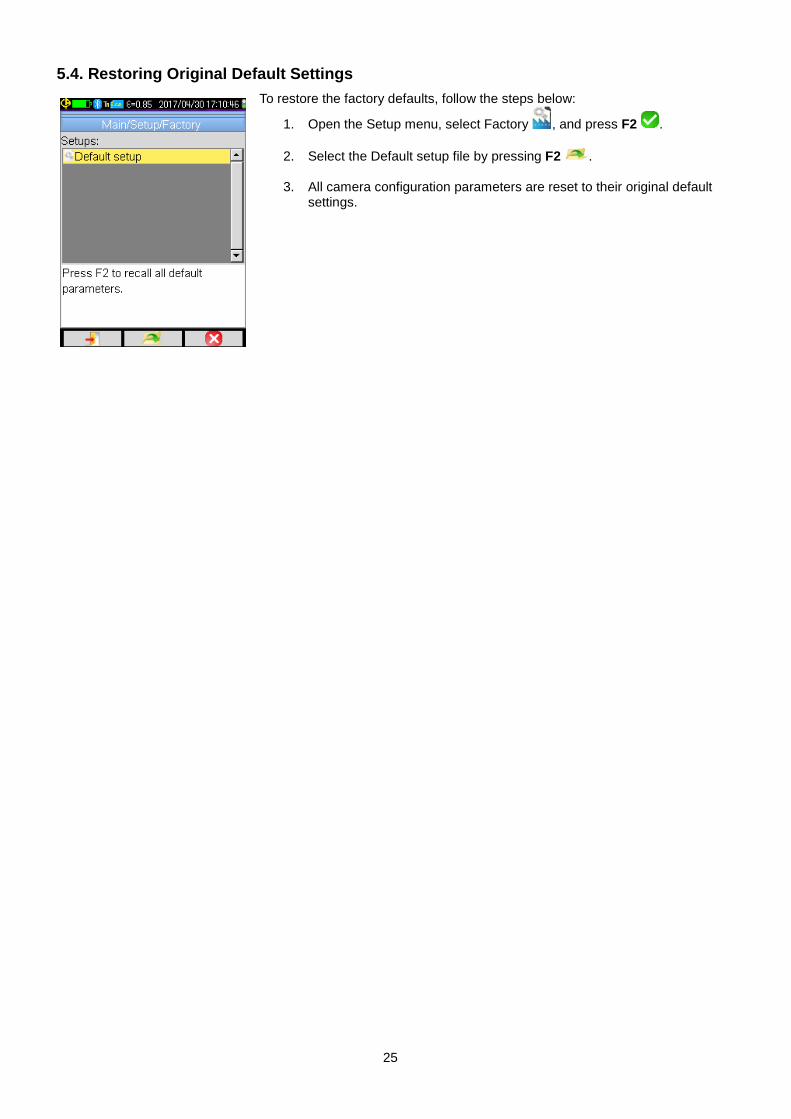
5.4. Restoring Original Default Settings To restore the factory defaults, follow the steps below:
1. Open the Setup menu, select Factory , and press F2 .
2. Select the Default setup file by pressing F2 .
3. All camera configuration parameters are reset to their original default settings.
25
6. BLUETOOTH
6.1. Bluetooth Activation/Deactivation The camera uses Bluetooth to wirelessly communicate with the headset and compatible AEMC measurement instruments.
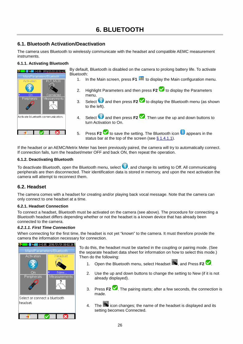
6.1.1. Activating Bluetooth By default, Bluetooth is disabled on the camera to prolong battery life. To activate Bluetooth:
1. In the Main screen, press F1 to display the Main configuration menu.
2. Highlight Parameters and then press F2 to display the Parameters menu.
3. Select and then press F2 to display the Bluetooth menu (as shown to the left).
4. Select and then press F2 . Then use the up and down buttons to turn Activation to On.
5. Press F2 to save the setting. The Bluetooth icon appears in the status bar at the top of the screen (see § 1.4.1.1).
If the headset or an AEMC/Metrix Meter has been previously paired, the camera will try to automatically connect. If connection fails, turn the headset/meter OFF and back ON, then repeat the operation.
6.1.2. Deactivating Bluetooth
To deactivate Bluetooth, open the Bluetooth menu, select , and change its setting to Off. All communicating peripherals are then disconnected. Their identification data is stored in memory, and upon the next activation the camera will attempt to reconnect them.
6.2. Headset The camera comes with a headset for creating and/or playing back vocal message. Note that the camera can only connect to one headset at a time.
6.2.1. Headset Connection To connect a headset, Bluetooth must be activated on the camera (see above). The procedure for connecting a Bluetooth headset differs depending whether or not the headset is a known device that has already been connected to the camera. 6.2.1.1. First Time Connection When connecting for the first time, the headset is not yet “known” to the camera. It must therefore provide the camera the information necessary for connection.
To do this, the headset must be started in the coupling or pairing mode. (See the separate headset data sheet for information on how to select this mode.) Then do the following:
1. Open the Bluetooth menu, select Headset , and Press F2 .
2. Use the up and down buttons to change the setting to New (if it is not already displayed).
3. Press F2 . The pairing starts; after a few seconds, the connection is made.
4. The icon changes; the name of the headset is displayed and its setting becomes Connected.
26
6.2.1.2. Headset is a Known Device If the headset is known, there is no need for pairing; simply power up the headset. Then open the Bluetooth
menu, select , and select Connect. The headset should connect after a few seconds (the icon status is displayed as Connected). If connection fails, switch the headset off and back on and repeat the operation.
If the name of the headset does not appear in the title of the icon, pairing has failed and you must try again.
6.2.2. Changing Headsets To change headsets, switch OFF the currently connected headset. Then connect the new headset as an unknown device, as instructed in § 6.2.1.
6.2.3. Headset Disconnection The procedure for disconnecting a headset depends on whether or not other Bluetooth devices are connected to the camera:
Measurement devices are connected to your camera and you want to leave them connected. The simplest solution is to switch off the headset. You can also disconnect it via the Bluetooth menu by changing the status to Disconnect.
No other device is connected to your camera. We recommend deactivating Bluetooth as explained in § 6.1.2. Deactivating Bluetooth significantly reduces energy consumption and prolongs battery life.
6.3. Measurement Devices In addition to the headset, you can simultaneously connect up to three AEMC measurement devices to the camera via Bluetooth. The following AEMC meters are supported:
Metrix ASYC IV Multimeters Models MTX 3292-BT and 3293-BT (1 measurement read) AEMC Power Clamp-on Meter Model 607 (3 measurements read) AEMC Power Clamp-on Meter 407 (3 measurements read)
Measurement data from connected devices can be displayed on the screen, and saved along with the image. They can be viewed when the image file is recalled (see § 4.4). Measurement data can also be used to compensate for environmental factors. To maintain consistency between the Bluetooth measurements and the displayed image, measurements are refreshed continuously during image acquisition. The refresh frequency is defined by the measurement polling period setting (see below). When you freeze the image, displayed measurements also freeze.
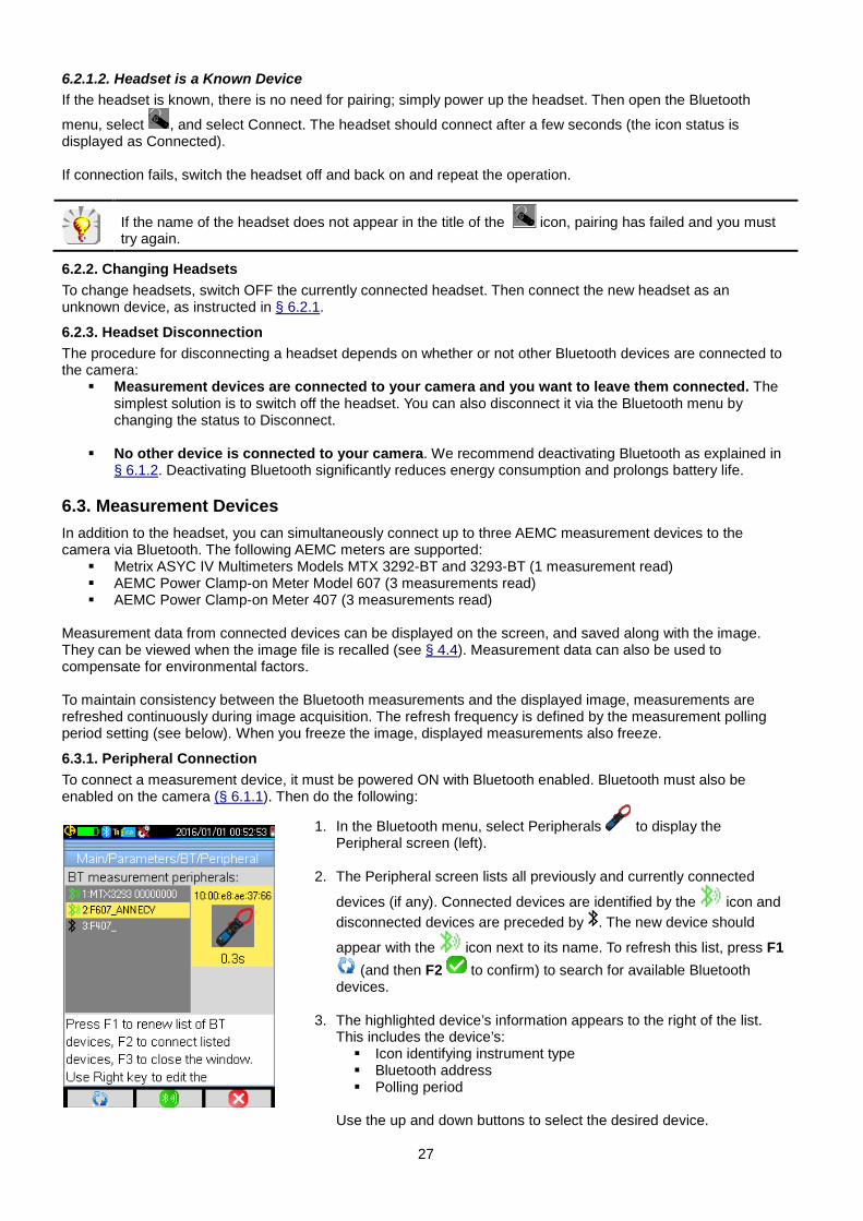
6.3.1. Peripheral Connection To connect a measurement device, it must be powered ON with Bluetooth enabled. Bluetooth must also be enabled on the camera (§ 6.1.1). Then do the following:
1. In the Bluetooth menu, select Peripherals to display the Peripheral screen (left).
2. The Peripheral screen lists all previously and currently connected
devices (if any). Connected devices are identified by the icon and disconnected devices are preceded by . The new device should
appear with the icon next to its name. To refresh this list, press F1 (and then F2 to confirm) to search for available Bluetooth
devices.
3. The highlighted device’s information appears to the right of the list. This includes the device’s: Icon identifying instrument type Bluetooth address Polling period
Use the up and down buttons to select the desired device.
27
F1, F2, and F3 in this screen function as follows:
F1 Search for Bluetooth devices. Devices already connected remain on the list. Those having the highest signal levels are added and connected until the three connected devices maximum is reached.
F2 Reconnect all devices in the list.
F3 Close the Peripheral screen.
If the screen is frozen when you connect a device, measurements from the device will not appear in the Measurements screen until you unfreeze the image and start the next image acquisition.
6.3.2. Replacing Devices 1. Disconnect the device to be removed by turning it OFF.
2. Wait until the disconnection takes effect on the camera (a message appears informing you of this).
3. Turn ON the new device to be connected.
4. With the Peripherals screen displayed, start a new search by pressing F1 . This overwrites the list
(currently connected devices remain). The new device should be included in this list.
6.3.3. Device Polling Period The polling period defines the frequency with which the camera “polls” the device for measurement data. To change this:
1. In the Peripherals screen, select the device in the list and press the right button. The polling period is highlighted in blue, with the symbol indicating that it can be changed.
2. Use the up and down buttons to select a new polling period. Options range from 0.3s up to 50 minutes.
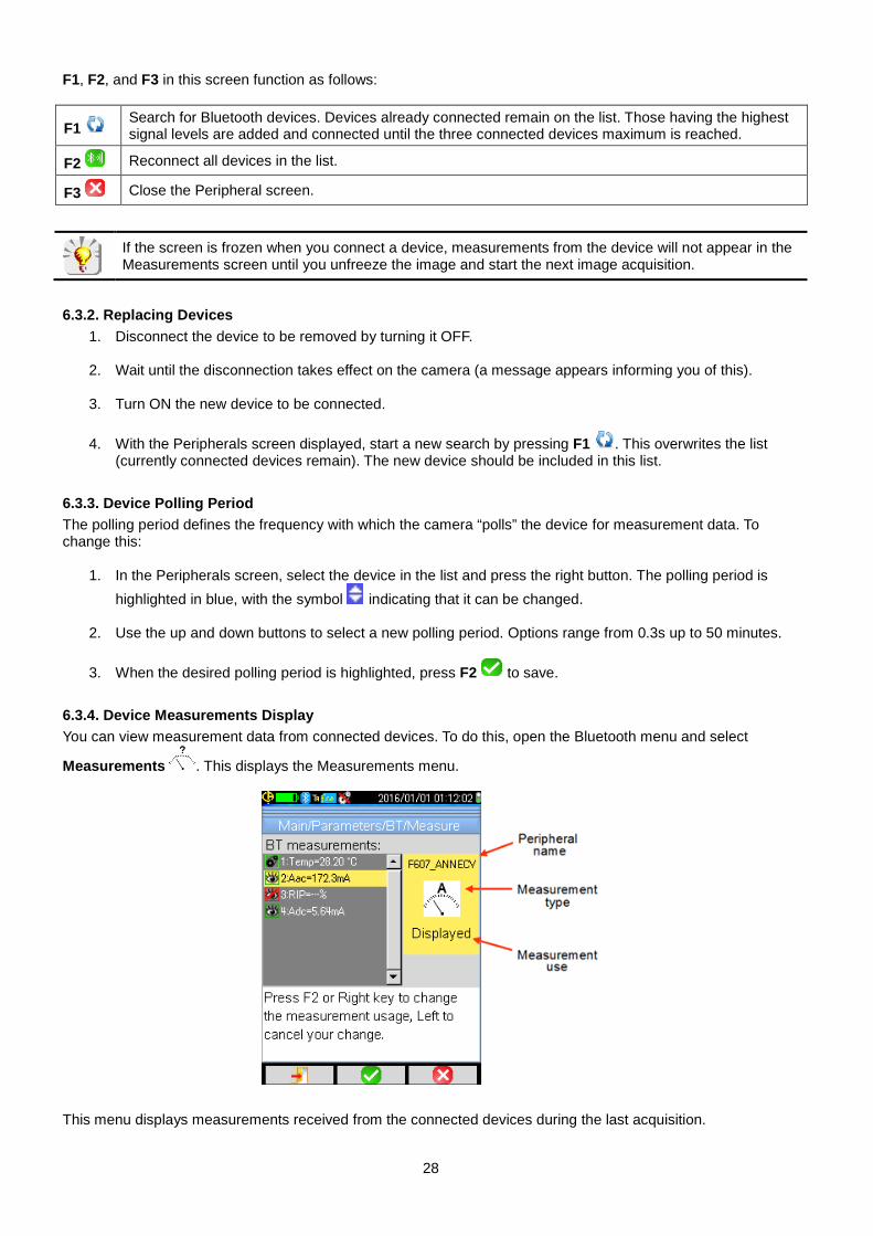
3. When the desired polling period is highlighted, press F2 to save. 6.3.4. Device Measurements Display You can view measurement data from connected devices. To do this, open the Bluetooth menu and select
Measurements . This displays the Measurements menu.
This menu displays measurements received from the connected devices during the last acquisition.
28
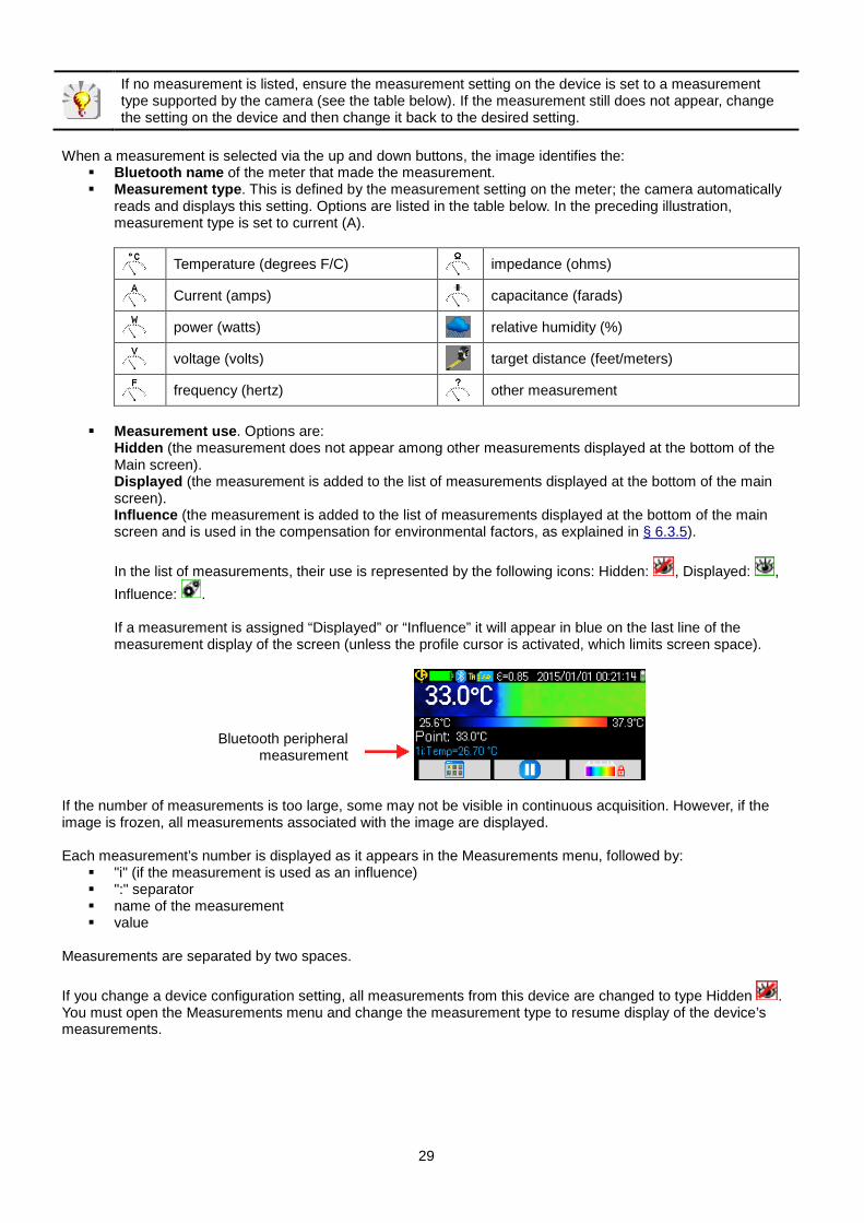
If no measurement is listed, ensure the measurement setting on the device is set to a measurement type supported by the camera (see the table below). If the measurement still does not appear, change the setting on the device and then change it back to the desired setting.
When a measurement is selected via the up and down buttons, the image identifies the:
Bluetooth name of the meter that made the measurement. Measurement type. This is defined by the measurement setting on the meter; the camera automatically
reads and displays this setting. Options are listed in the table below. In the preceding illustration, measurement type is set to current (A).
Temperature (degrees F/C) impedance (ohms)
Current (amps) capacitance (farads)
power (watts) relative humidity (%)
voltage (volts) target distance (feet/meters)
frequency (hertz) other measurement
Measurement use. Options are: Hidden (the measurement does not appear among other measurements displayed at the bottom of the Main screen). Displayed (the measurement is added to the list of measurements displayed at the bottom of the main screen). Influence (the measurement is added to the list of measurements displayed at the bottom of the main screen and is used in the compensation for environmental factors, as explained in § 6.3.5). In the list of measurements, their use is represented by the following icons: Hidden: , Displayed: , Influence: . If a measurement is assigned “Displayed” or “Influence” it will appear in blue on the last line of the measurement display of the screen (unless the profile cursor is activated, which limits screen space).
Bluetooth peripheral measurement
If the number of measurements is too large, some may not be visible in continuous acquisition. However, if the image is frozen, all measurements associated with the image are displayed. Each measurement’s number is displayed as it appears in the Measurements menu, followed by:
"i" (if the measurement is used as an influence) ":" separator name of the measurement value
Measurements are separated by two spaces. If you change a device configuration setting, all measurements from this device are changed to type Hidden . You must open the Measurements menu and change the measurement type to resume display of the device’s measurements.
29
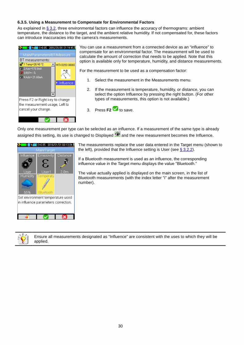
6.3.5. Using a Measurement to Compensate for Environmental Factors As explained in § 3.2, three environmental factors can influence the accuracy of thermograms: ambient temperature, the distance to the target, and the ambient relative humidity. If not compensated for, these factors can introduce inaccuracies into the camera’s measurements.
You can use a measurement from a connected device as an “influence” to compensate for an environmental factor. The measurement will be used to calculate the amount of correction that needs to be applied. Note that this option is available only for temperature, humidity, and distance measurements. For the measurement to be used as a compensation factor:
1. Select the measurement in the Measurements menu.
2. If the measurement is temperature, humidity, or distance, you can select the option Influence by pressing the right button. (For other types of measurements, this option is not available.)
3. Press F2 to save.
Only one measurement per type can be selected as an influence. If a measurement of the same type is already assigned this setting, its use is changed to Displayed and the new measurement becomes the Influence.
The measurements replace the user data entered in the Target menu (shown to the left), provided that the Influence setting is User (see § 3.2.2). If a Bluetooth measurement is used as an influence, the corresponding influence value in the Target menu displays the value "Bluetooth.” The value actually applied is displayed on the main screen, in the list of Bluetooth measurements (with the index letter "i" after the measurement number).
Ensure all measurements designated as “Influence” are consistent with the uses to which they will be applied.
30
7. FIRMWARE UPDATES
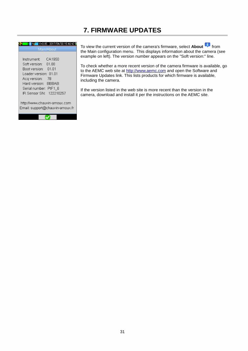
To view the current version of the camera's firmware, select About from the Main configuration menu. This displays information about the camera (see example on left). The version number appears on the "Soft version:" line. To check whether a more recent version of the camera firmware is available, go to the AEMC web site at http://www.aemc.com and open the Software and Firmware Updates link. This lists products for which firmware is available, including the camera. If the version listed in the web site is more recent than the version in the camera, download and install it per the instructions on the AEMC site.
31
8. TROUBLESHOOTING
8.1. IR Image is a Single Solid Color 8.1.1. Color Palette Frozen Ensure the low and high temperature limits of your palette are consistent with the temperature range in your environment. To check this, unlock the palette (see § 2.2).
8.1.2. Inconsistent "User" Influencing Parameters An incorrect emissivity value can result in measurement errors. Check the influencing parameters in the Target menu (see § 3.2). If you question any of the settings, restore the default parameters (see § 3.2.1).
8.2. Contrast of IR Image is Incorrect Ensure that Isotherm measurement is not activated (see § 2.1.6).
If the palette is frozen, ensure that the low and high temperature limits are consistent with the
temperature range in your environment. To check this, unlock the palette (see § 2.2).
If the temperature range of the image is very large (hot and cold points are very far apart), the linear distribution of the colors between the minimum and maximum temperatures will be in large steps. This impairs the image contrast. To address this, do one of the following: - Freeze the palette and set the limits to the temperature range of highest interest. - Keep the hot or cold point of lower interest outside the field of view of the camera, to reduce the
temperature range of the image.
8.3. Unable to Save Displayed Image Ensure that the micro SD card is correctly inserted in its slot, and that the status bar indicates the card is
present (see § 1.4.1.1).
Check the micro SD card to see if it is full (with FAT16 formatting, check the number of entries in the root; see § 1.5.7).
Ensure the micro SD card is not corrupted and that you can read/modify its content on a computer via the USB cable or a card reader (see § 4.6).
8.4. Slow Opening of Files The access time to the micro SD card is relatively long. To shorten it, you can create new directories to store images and limit the number of files per directory. We suggest regularly uploading your images to a host computer via the USB cable or a card reader.
8.5. Headset Cannot Connect to Camera Ensure the headset is powered ON and that it is not connected to another instrument with which you
have already paired it.
Switch the headset OFF and repeat the connection procedure described in § 6.2.1.
If the problem persists, deactivate Bluetooth on the camera (see § 6.1.2), re-activate it, and then attempt to connect.
8.6. Bluetooth Device Cannot Connect to Camera Ensure the device is powered ON with Bluetooth activated, and not already used by another instrument.
Turn OFF the device and repeat the connection procedure (see § 6.3).
If the problem persists, deactivate the Bluetooth function on the camera (see § 6.1.2), re-activate it, and
then attempt to connect.
32
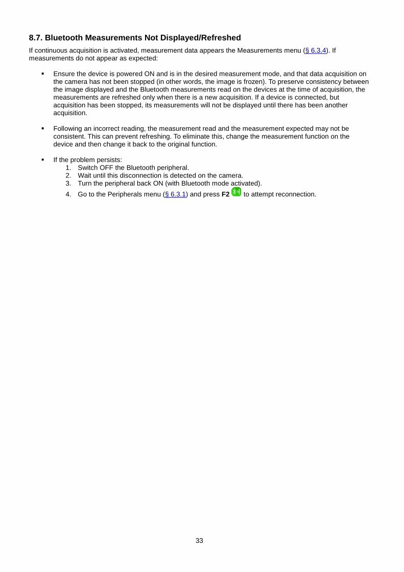
8.7. Bluetooth Measurements Not Displayed/Refreshed If continuous acquisition is activated, measurement data appears the Measurements menu (§ 6.3.4). If measurements do not appear as expected:
Ensure the device is powered ON and is in the desired measurement mode, and that data acquisition on the camera has not been stopped (in other words, the image is frozen). To preserve consistency between the image displayed and the Bluetooth measurements read on the devices at the time of acquisition, the measurements are refreshed only when there is a new acquisition. If a device is connected, but acquisition has been stopped, its measurements will not be displayed until there has been another acquisition.
Following an incorrect reading, the measurement read and the measurement expected may not be consistent. This can prevent refreshing. To eliminate this, change the measurement function on the device and then change it back to the original function.
If the problem persists: 1. Switch OFF the Bluetooth peripheral. 2. Wait until this disconnection is detected on the camera. 3. Turn the peripheral back ON (with Bluetooth mode activated). 4. Go to the Peripherals menu (§ 6.3.1) and press F2 to attempt reconnection.
33
9. MAINTENANCE
9.1. Camera Cleaning
WARNING! The camera is not waterproof.
Housing: To avoid any spattering on the lens, close the camera's lens protection flap. To clean, use acloth moistened with soapy water or with alcohol.
Screen: To avoid scratching, use a soft, lint-free cloth.
9.2. Infrared Optics Cleaning
WARNING! The infrared lens coating is very fragile.
Avoid leaving fingerprints on the lens.
Avoid rubbing the lens unnecessarily.
If there is dust on the lens, if possible use non-contact cleaning methods such as compressed drynitrogen, an air bulb, and so on.
If you must wipe the lens, first use air to blow away as much dust as possible. Then clean the lens with asoft, absorbent, lint-free optical lens cleaning paper such as KIMWIPE.
34
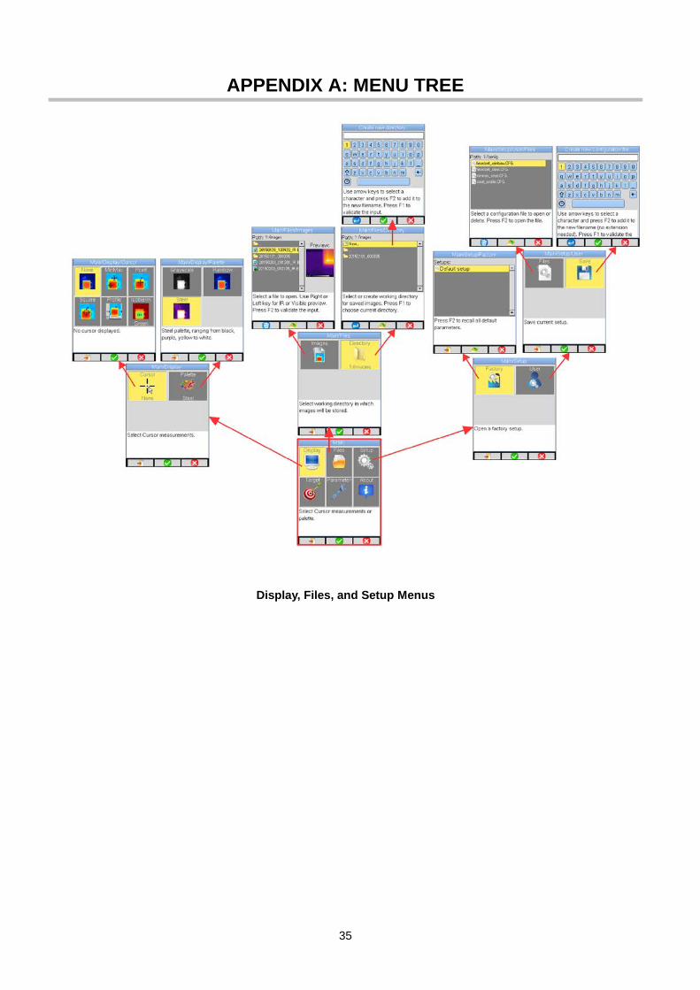
APPENDIX A: MENU TREE
Display, Files, and Setup Menus
35
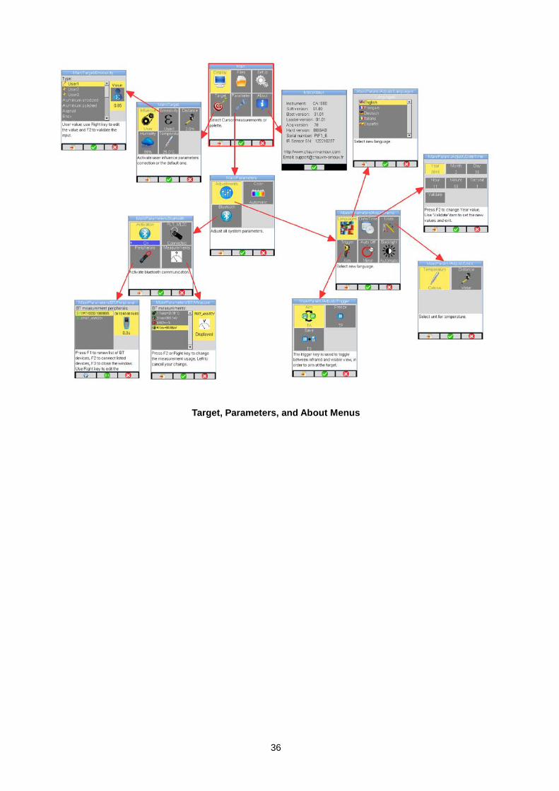
Target, Parameters, and About Menus
36
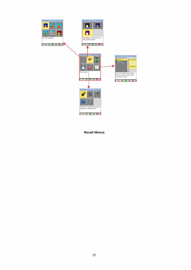
Recall Menus
37
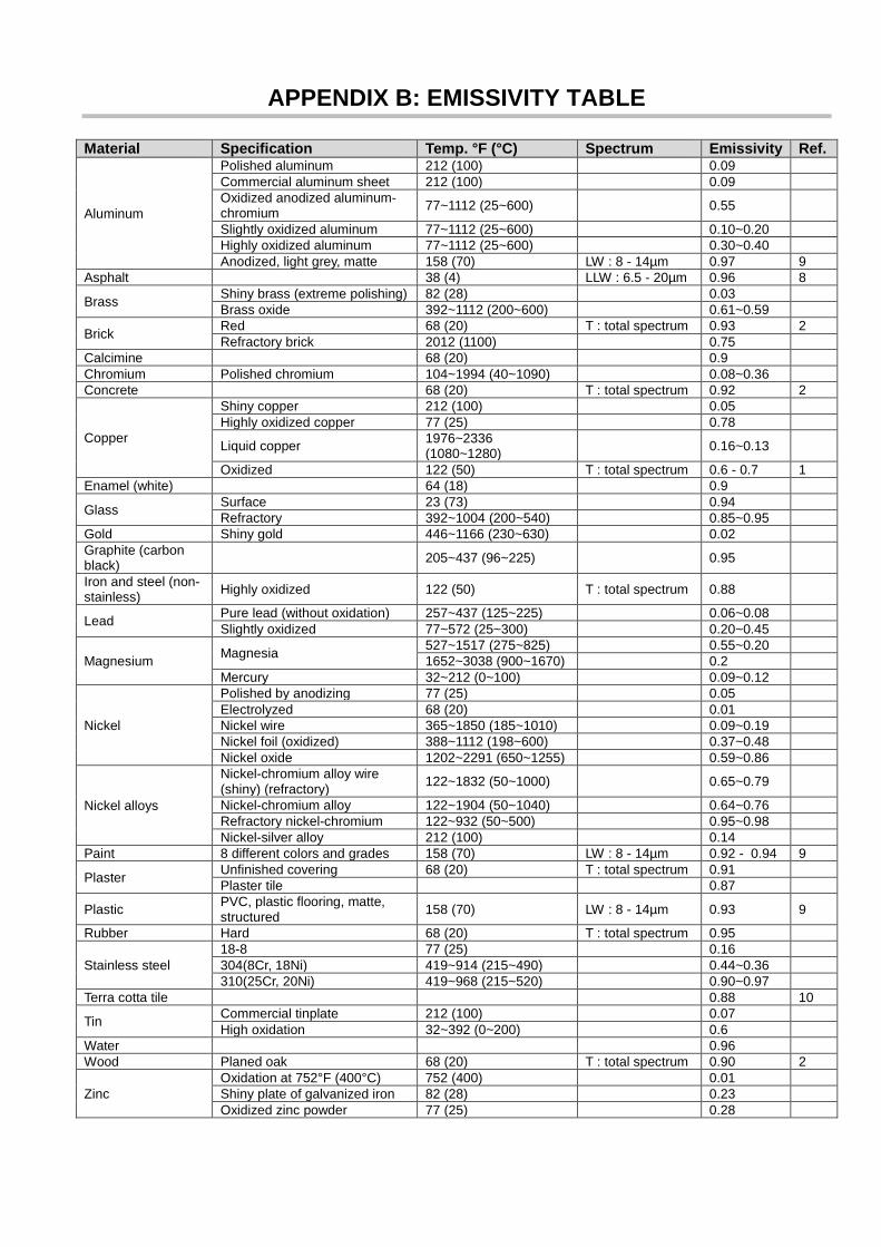
APPENDIX B: EMISSIVITY TABLE
Material Specification Temp. °F (°C) Spectrum Emissivity Ref.
Aluminum
Polished aluminum 212 (100) 0.09 Commercial aluminum sheet 212 (100) 0.09 Oxidized anodized aluminum-chromium 77~1112 (25~600) 0.55
Slightly oxidized aluminum 77~1112 (25~600) 0.10~0.20 Highly oxidized aluminum 77~1112 (25~600) 0.30~0.40 Anodized, light grey, matte 158 (70) LW : 8 - 14µm 0.97 9
Asphalt 38 (4) LLW : 6.5 - 20µm 0.96 8
Brass Shiny brass (extreme polishing) 82 (28) 0.03 Brass oxide 392~1112 (200~600) 0.61~0.59
Brick Red 68 (20) T : total spectrum 0.93 2 Refractory brick 2012 (1100) 0.75
Calcimine 68 (20) 0.9 Chromium Polished chromium 104~1994 (40~1090) 0.08~0.36 Concrete 68 (20) T : total spectrum 0.92 2
Copper
Shiny copper 212 (100) 0.05 Highly oxidized copper 77 (25) 0.78
Liquid copper 1976~2336 (1080~1280) 0.16~0.13
Oxidized 122 (50) T : total spectrum 0.6 - 0.7 1 Enamel (white) 64 (18) 0.9
Glass Surface 23 (73) 0.94 Refractory 392~1004 (200~540) 0.85~0.95
Gold Shiny gold 446~1166 (230~630) 0.02 Graphite (carbon black) 205~437 (96~225) 0.95
Iron and steel (non-stainless) Highly oxidized 122 (50) T : total spectrum 0.88
Lead Pure lead (without oxidation) 257~437 (125~225) 0.06~0.08 Slightly oxidized 77~572 (25~300) 0.20~0.45
Magnesium Magnesia 527~1517 (275~825) 0.55~0.20 1652~3038 (900~1670) 0.2
Mercury 32~212 (0~100) 0.09~0.12
Nickel
Polished by anodizing 77 (25) 0.05 Electrolyzed 68 (20) 0.01 Nickel wire 365~1850 (185~1010) 0.09~0.19 Nickel foil (oxidized) 388~1112 (198~600) 0.37~0.48 Nickel oxide 1202~2291 (650~1255) 0.59~0.86
Nickel alloys
Nickel-chromium alloy wire (shiny) (refractory) 122~1832 (50~1000) 0.65~0.79
Nickel-chromium alloy 122~1904 (50~1040) 0.64~0.76 Refractory nickel-chromium 122~932 (50~500) 0.95~0.98 Nickel-silver alloy 212 (100) 0.14
Paint 8 different colors and grades 158 (70) LW : 8 - 14µm 0.92 - 0.94 9
Plaster Unfinished covering 68 (20) T : total spectrum 0.91 Plaster tile 0.87
Plastic PVC, plastic flooring, matte, structured 158 (70) LW : 8 - 14µm 0.93 9
Rubber Hard 68 (20) T : total spectrum 0.95
Stainless steel 18-8 77 (25) 0.16 304(8Cr, 18Ni) 419~914 (215~490) 0.44~0.36 310(25Cr, 20Ni) 419~968 (215~520) 0.90~0.97
Terra cotta tile 0.88 10
Tin Commercial tinplate 212 (100) 0.07 High oxidation 32~392 (0~200) 0.6
Water 0.96 Wood Planed oak 68 (20) T : total spectrum 0.90 2
Zinc Oxidation at 752°F (400°C) 752 (400) 0.01 Shiny plate of galvanized iron 82 (28) 0.23 Oxidized zinc powder 77 (25) 0.28
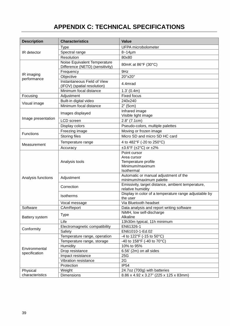
APPENDIX C: TECHNICAL SPECIFICATIONS
Description Characteristics Value
IR detector Type UFPA microbolometer Spectral range 8~14µm Resolution 80x80
IR imaging performance
Noise Equivalent Temperature Difference (NETD) (sensitivity) 80mK at 86°F (30°C)
Frequency 9Hz Objective 20°x20° Instantaneous Field of View (IFOV) (spatial resolution) 4.4mrad
Minimum focal distance 1.3’ (0.4m) Focusing Adjustment Fixed focus
Visual image Built-in digital video 240x240 Minimum focal distance 2” (5cm)
Image presentation Images displayed Infrared image
Visible light image LCD screen 2.8” (7.1cm) Display colors Pseudo-colors, multiple palettes
Functions Freezing image Moving or frozen image Storing files Micro SD and micro SD HC card
Measurement Temperature range 4 to 482°F (-20 to 250°C) Accuracy ±3.6°F (±2°C) or ±2%
Analysis functions
Analysis tools
Point cursor Area cursor Temperature profile Minimum/maximum Isothermal
Adjustment Automatic or manual adjustment of the minimum/maximum palette
Correction Emissivity, target distance, ambient temperature, relative humidity
Isotherms Display in color of a temperature range adjustable by the user
Vocal message Via Bluetooth headset Software CAmReport Data analysis and report writing software
Battery system Type NiMH, low self-discharge Alkaline
Life 13h30m typical, 11h minimum
Conformity Electromagnetic compatibility EN61326-1 Safety EN61010-1-Ed.02
Environmental specification
Temperature range, operation -4 to 122°F (-15 to 50°C) Temperature range, storage -40 to 158°F (-40 to 70°C) Humidity 10% to 95% Drop resistance 6.56’ (2m) on all sides Impact resistance 25G Vibration resistance 2G Protection IP54
Physical characteristics
Weight 24.7oz (700g) with batteries Dimensions 8.86 x 4.92 x 3.27” (225 x 125 x 83mm)
39

REPAIR AND CALIBRATION
To ensure your instrument meets factory specifications, we recommend that it be scheduled to be sent back to our factory Service Center at one-year intervals for recalibration, or as required by other standards or internal procedures. For instrument repair and calibration: You must contact our Service Center for a Customer Service Authorization Number (CSA#). This will ensure that when your instrument arrives, it will be tracked and processed promptly. Please write the CSA# on the outside of the shipping container. If the instrument is returned for calibration, we need to know if you want a standard calibration, or a calibration traceable to N.I.S.T. (Includes calibration certificate plus recorded calibration data). Ship To: Chauvin Arnoux®, Inc. d.b.a. AEMC® Instruments 15 Faraday Drive • Dover, NH 03820 USA Phone: (800) 945-2362 (Ext. 360) (603) 749-6434 (Ext. 360) Fax: (603) 742-2346 or (603) 749-6309 E-mail: [email protected] (Or contact your authorized distributor.) Costs for repair, standard calibration, and calibration traceable to N.I.S.T. are available. NOTE: You must obtain a CSA# before returning any instrument.
TECHNICAL AND SALES ASSISTANCE
If you are experiencing any technical problems, or require any assistance with the proper operation or application of your instrument, please call, fax, or e-mail our technical support team:
Chauvin Arnoux®, Inc. d.b.a. AEMC® Instruments Phone: (800) 343-1391 • (508) 698-2115 Fax: (508) 698-2118 E-mail: [email protected]
LIMITED WARRANTY
The IR Camera Model 1950 is warranted to the owner for a period of two years from the date of original purchase against defects in manufacture. This limited warranty is given by AEMC® Instruments, not by the distributor from whom it was purchased. This warranty is void if the unit has been tampered with, abused or if the defect is related to service not performed by AEMC® Instruments. Full warranty coverage and product registration is available on our website at: www.aemc.com/warranty.html. Please print the online Warranty Coverage Information for your records. If a malfunction occurs within the warranty period, you may return the instrument to us for repair, provided we have your warranty registration information on file or a proof of purchase. AEMC® Instruments will, at its option, repair or replace the faulty material. REGISTER ONLINE AT: www.aemc.com.
40

Warranty Repairs What you must do to return an Instrument for Warranty Repair: First, request a Customer Service Authorization Number (CSA#) by phone or by fax from our Service Department (see address below), then return the instrument along with the signed CSA Form. Please write the CSA# on the outside of the shipping container. Return the instrument, postage or shipment pre-paid to: Ship To: Chauvin Arnoux®, Inc. d.b.a. AEMC® Instruments
15 Faraday Drive • Dover, NH 03820 USA Phone: (800) 945-2362 (Ext. 360)
(603) 749-6434 (Ext. 360) Fax: (603) 742-2346 or (603) 749-6309 E-mail: [email protected]
Caution: To protect yourself against in-transit loss, we recommend you insure your returned material. NOTE: You must obtain a CSA# before returning any instrument.
41

NOTES:
42

NOTES:
43

99-MAN 100432 v3 08/18
Chauvin Arnoux®, Inc. d.b.a. AEMC® Instruments 15 Faraday Drive • Dover, NH 03820 USA • Phone: (603) 749-6434 • Fax: (603) 742-2346
www.aemc.com