
Thermal Behaviour Analysis of Permanent Magnet Motors · Thermal Behaviour Analysis of Permanent...
49
Thermal Behaviour Analysis of Permanent Magnet Motors Magnetic Materials in Electrical Machines Applications Pori, Finland, 6 November 2009 Mircea Popescu Motor Design Ltd. U.K.
Transcript of Thermal Behaviour Analysis of Permanent Magnet Motors · Thermal Behaviour Analysis of Permanent...

Thermal Behaviour Analysis of Permanent Magnet Motors
Magnetic Materials in Electrical Machines Applications
Pori, Finland, 6 November 2009
Mircea PopescuMotor Design Ltd. U.K.

Topics
1. Motor Design Ltd
2. Importance of Thermal Analysis in PM Motors
3. Traditional and Modern Thermal Design Methods
2
3. Traditional and Modern Thermal Design Methods
4. Thermal networks for PM motors
5. Examples of thermal analysis of PM motors

Motor Design Ltd
• Motor-CAD Developers
• Distributors in UK– SPEED Software– Motor-CAD– FLUX– Portunus
3
• Contact details
Lloyds Bank Chambers4 Scotland Street, Ellesmere,ShropshireSY12 0EG, U.K.+44 (0) 1691 623305www.motor-design.com

Importance ofImportance ofThermal Analysis in PM MotorsThermal Analysis in PM Motors
44

Importance of Thermal Analysis in PM Motors
• Increased competition giving requirement for improved design capabilities
• There is a strong requirement for more energy efficient motors
5
efficient motors – Improved thermal design can lead to a cooler machine
with reduced losses• Copper loss is a function of winding resistance and so temperature• Permanent magnet flux reduces with increased temperature
• Requirement to have a good match between motor and load for complex duty cycle applications

Importance of Thermal Analysis in PM Motors
• motor size is ultimately dependant upon thermal rating
• the component with the limitingtemperature may be the:
• wire or slot liner/impregnation• bearings (life)• magnet (loss of flux and
demagnetiation withstand)
6
demagnetiation withstand)• plastic cover• encoder• housing (safety limit)
• the temperature of the windinginsulation has a large impact on thelife of the machine
• many companies use curves suchas that shown to estimate motor life– very important in some industries

Importance of Thermal Analysis in PM Motors
Example of duty cycle:
7
• Magnets are usually isolated from the main heat sources.– Somewhat protected from severe transient overloads– Rare earth magnets (SmCo, sintered NdFeB) exhibit local eddy-
current losses as heat source– Difficult to estimate or measure losses– Longer time constant for magnet compared to winding– Essential to know magnet temperature for transient and
demagnetization calculation

Traditional and ModernTraditional and ModernThermal Design MethodsThermal Design Methods
• Rules of thumb• Lumped circuit analysis
88
• Lumped circuit analysis• Numerical analysis

Traditional Thermal Sizing Methods
• Sizing based on single parameter– thermal resistance– housing heat transfer coefficient– winding current density– specific electric loading
• Thermal data from– simple rules of thumb
TwindingTambient
RTH [oC/W]P [W]
Thermal Resistance
9
– simple rules of thumb• 5 A/mm2, 12 W/m2/C etc.
– tests on existing motors– competitor catalogue data
• Can be inaccurate– single parameter fails to describe
complex nature of motor cooling
• Poor insight of where to concentrate design effort
h [W/(m2.oC)]
Heat Transfer Coefficient

Rules of Thumb (Examples)• Air Natural Convection
h = 5-10 W/(m2.C)• Air Forced Convection
h =10-300 W/(m2.C)• Liquid Forced Convection
h = 50-20000 W/(m2.C)
10
• Wide range of possible values makes past experience very important• the design might not be correctly sized• problems if there is not enough experience on design type being investigated• more detailed mathematical modelling approach makes rules of thumb less important

Modern Thermal Design Techniques
Thermal Design Options Available:
• Lumped Circuit Analysis (Network Analysis)
11
• Numerical Analysis
– Finite Element Analysis
– Computational Fluid Dynamics (CFD)

Thermal Lumped Circuit Models
• Similar to electrical network so easy to understand by electrical engineers
– thermal resistances rather than electrical resistances
– power sources rather than current sources
12
current sources
– thermal capacitances rather than electrical capacitors (not shown here)
– nodal temperatures rather than voltages
– power flow through resistances rather than current

• Thermal resistances placed in the circuit to model heat transfer paths in the machine
– conduction (R = L/kA)• path area (A) and length (L) from geometry, thermal conductivity (k) of material
• complexity in composite component such as the winding
– convection (R = 1/hA)• heat transfer coefficient (h – W/m2.C) from empirical dimensionless analysis
formulations (correlations)
Thermal Lumped Circuit Models
13
formulations (correlations)
– proven correlations for all kinds of geometry in heat transfer technical literature –just select most appropriate formulation
– radiation (R = 1/hA)• h = σ ε1 F1-2 (T1
4 – T24)/ (T1 – T2)
• emissivity (ε1) & view factor (F1-2) from surface finish & geometry
• power input at nodes where losses occur• thermal capacitances for transient analysis
– Capacitance = Weight × Specific Heat Capacity of material

Numerical Thermal Analysis• Two basic types available:
– finite element analysis (FEA)• useful to accurately calculate conduction heat
transfer
– computational fluid dynamics (CFD)• automatically calculates fluid flow
CFD
14
• automatically calculates fluid flow
FEACFD CFD

Computational Fluid Dynamics (CFD)• the expected accuracy is not as
great as with electromagnetic FEA – due to complexities of geometry and
turbulent fluid flow
• often impossible to model actual geometry perfectly and difficult to account for imperfections
15
to account for imperfections such as interface gaps
• can be very time consuming to construct a model and then calculate (especially transient)– Computation time can take several
weeks/months
• best use of results to calibrate analytical formulations

Thermal Networks for PM MotorsThermal Networks for PM Motors
1616

Thermal networksExample of Input
17
Example of Output

Cooling TypesThermal networks include proven models for an extensive range of cooling types
– Natural Convection (TENV)• many housing design types
– Forced Convection – (TEFC)• many fin channel design types
– Through Ventilation• rotor and stator cooling ducts
– Open end-shield cooling– Water Jackets
18
– Water Jackets • many design types (axial and circumferential ducts)• stator and rotor water jackets
– Submersible cooling– Wet Rotor & Wet Stator cooling– Spray Cooling– Direct conductor cooling
• Slot water jacket
– Conduction • Internal conduction and the effects of mounting
– Radiation• Internal and external

Selection the Cooling Method
• Fins– Radial– Axial
• Shaft Cooling– Hollow– Spiral Groove
• Water Jackets– Radial Fluid Flow
• Fluid Down Gap– Wet Rotor
19
– Radial Fluid Flow– Axial Fluid Flow– Serpentine Flow– Rotor water jacket– Slot water jacket, etc
– Wet Rotor– Wet Stator
• Spray• Mounting –
conduction
• Radiation

Housing Types
20
• Many housing designs can be modeled and optimized– the designer selected a housing type that is appropriate for the cooling type to be used and
then optimizes the dimensions, e.g. axial fin dimensions and spacing for a TEFC machine

Surface and Interior Permanent Magnet Geometries
21
• E.g. SMPM and IPM with V shaped magnets and servo housing

Radial & Axial Cross-Section• Geometry has to be
described using the dedicated radial & axial cross-section editors
– input the dimensions of the design under consideration
– both the radial and axial cross-section are defined because end effects such
22
because end effects such as gaps around the end winding can have a significant impact on cooling

Water Jackets
23
• Spiral grove and zig-zag housing jackets with choice on parameters such as channel dimensions, parallel paths, inlet and out positions, etc.

Rotor Water Jacket
• Rotor water jacket may be useful in some specialist BPM applications– air/fluid between the magnets
24

Slot Water Jacket
• A slot water jacket may be useful in very highly loaded machines (fluid in the slot)
25

BPMOR Rotor Mounting
• The outer rotor BPM machine is often embedded inside equipment, i.e. wheel
26
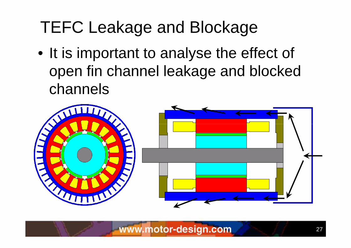
TEFC Leakage and Blockage
• It is important to analyse the effect of open fin channel leakage and blocked channels
27

Through Ventilation Model• Both the heat transfer and flow network analysis circuits may be
calculated for through ventilated machine
• The designer has to define the air flow paths according to the
stator and rotor ducting designs
28

Internal Radiation
• internal radiation can be very important in space applications or in wind power generation
29

Motor Mounting
30
• Mounting can have a significant impact on thermal behavior• 35% - 50% of total loss can be dissipated through the flange in
servo motor designs• NEMA rating test method for flange/foot mounted motors
allows the motor to be attached to a plate• The mounting can also be modeled using a fixed temperature
of a component or an amount of power input at a node

Losses• Losses are segregated into
the following components:– copper losses– iron losses– windage losses– bearings losses– magnet losses– proximity losses– stray losses
31
• Accuracy of temperature prediction depends on accuracy of loss prediction
• Algorithms need to model the loss variation with temperature, speed and load

Material Thermal Properties
32

Fluid Database
• Fluid property variation with temperature
• Windage loss variation with
33
variation with fluid properties has to be calculated

Interface Gaps• Used to investigate the
effect of interface gaps between components on thermal performance
– modeled as an effective airgap so giving physical insight to the user
– extensive testing has been done to validate thermal
Interface between two components with microscopic rough surfaces
34
done to validate thermal networks approach
• Using sensitivity analysis the designer can quickly and easily quantify the effect of manufacturing options and tolerances on the thermal performance

Manufacturing Uncertainties• The main difficulty in setting up an accurate thermal model
is in thermal network components that are influenced by manufacturing uncertainties, e.g. air in the winding impregnation, how good a fit there is between the stator lamination and housing, etc.– Measurements are necessary– Calibration using test can be used to give better absolute accuracy– The process of calibration and comparing parameters gives an
indication of how good the machine is constructed
35
indication of how good the machine is constructed – Sensitivity analysis is recommended to gain an in-depth
understanding of the main restrictions to cooling for a given design

Node Temperatures• Node temperature data give a quick
and easy method of visualizing the temperature distribution in the machine
36

Examples of thermal analysis of PM motors
3737

Segmented Motor MiniaturizationExisting Motor:
– 50mm active length– 130mm long housing– traditional lamination– overlapping winding
New Motor:– 50mm active length– 100mm long housing
38
– 100mm long housing– 34% more torque for same temperature rise– segmented lamination– non-overlapping winding
• In order to optimize the new design an iterative mix of electromagnetic and thermal analysis was performed
• Extensive thermal modeling input

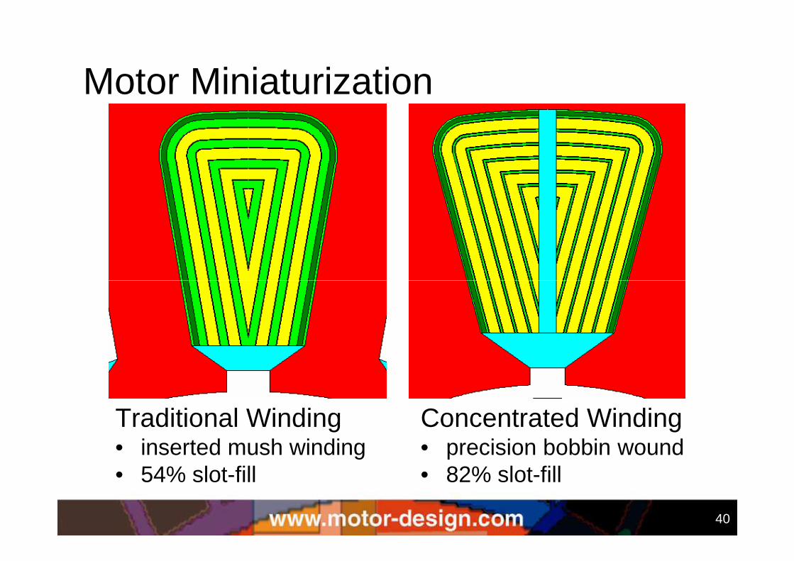
Motor Miniaturization
39
Traditional Winding• 80mm diameter• 18-slots, 6-poles• overlapping winding
Concentrated Winding• 80mm diameter• 12-slots, 8-poles• non-overlapping winding
Motor Miniaturization
40
Traditional Winding• inserted mush winding• 54% slot-fill
Concentrated Winding• precision bobbin wound• 82% slot-fill

Improved Impregnation
• Potting/impregnation materials was possible
41
• Potting/impregnation materials was possible– have k = 1W/m/C (and higher, but > 1 can be expensive)– previous materials have k = 0.2W/m/C– above design show 6%-8% reduction in temperature
• Above potted end-winding design showed a 15% reduced temperature compared to non-potted design

Improved Impregnation
42
• Vacuum impregnation can eliminate air pockets– above design shows 9% decrease in temperature in perfectly
impregnated motor compared to one with 50% impregnation

Servo Motor Fin Optimization
optimum fin spacing
oCNm
effect of flange cooling
43
• sophisticated analytical convection calculation formulations mean that CFD is NOT required to optimize the flow and heat transfer of the fins and fin channels
• small fin spacing has large surface area but reduced air flow• large fin spacing has maximum air flow but reduced surface area• as the motor is mounted to a flange cooling plate this has a significant
influence on the cooling of the short machine (machine has incremental 4 stack length variations)
spacing stack length

Automotive PMDC (Test/Calc)
20
40
60
80
100
120
140
160
180
200
220
Tem
pera
ture
[°C
]
Twinding [Test]Trotor [Test]Tmagnet [Test]Tcomm [Test]Thousing [Test]Twinding [Calc]Trotor [Calc]Tmagnet [Calc]Tcomm [Calc]Thousing [Calc]
44
• ICEM 2008 – electro-hydraulic brake• Optimisation impregnation process and
slot liner• Two transients shown
• Same load of 20A locked rotor• One has Nomex liner and the
other a powder liner • Powder liner takes much longer to
heat up
20
0 2 4 6 8 10time [min]
20
40
60
80
100
120
140
160
180
200
220
0 2 4 6 8 10 12 14 16 18time [min]
Tem
pera
ture
[°C
]
Twinding [Test]Trotor [Test]Tmagnet [Test]Tcomm [Test]Thousing [Test]Twinding [Calc]Trotor [Calc]Tmagnet [Calc]Tcomm [Calc]Thousing [Calc]

Servo Motor Duty Cycle Analysis
45

BPMOR Example 1• IECON 2006
– Water jacket– Modelled in thermal networks and FEA
• Similar results are obtained
46

BPMOR Example 2
• Wheel motor– Bristol University Project
47

BPMOR Example 2• Axle mounting has a significant influence on
the cooling
48

Thank You For Your AttentionThank You For Your Attention
Questions and AnswersQuestions and Answers
4949
Questions and AnswersQuestions and Answers


