THERMAL AND HYDRAULIC MACHINES LAB
34
THERMAL AND HYDRAULIC MACHINES LAB STUDENT REFERENCE MANUAL DEPARTMENT OF ELECTRICAL AND ELECTRONICS ENGINEERING
Transcript of THERMAL AND HYDRAULIC MACHINES LAB

THERMAL
AND
HYDRAULIC MACHINES LAB
STUDENT REFERENCE MANUAL
DEPARTMENT OF ELECTRICAL AND ELECTRONICS
ENGINEERING

PREFACE
.
The objective of this manual is to familiarize the students with practical skills,
measurement techniques and interpretation of results. It is intended to make this
manual self contained in all respects, so that it can be used as a laboratory manual. In
all the experiments, the relevant theory and general guidelines for the procedure to be
followed have been given. Tabular sheets for entering the observations have also been
provided in each experiment while graph sheets have been included wherever
necessary.
It is suggested that the students should complete the computations, is the
laboratory itself. However the students are advised to refer to the relevant text before
interpreting the results and writing a permanent discussion. The questions provided at
the end of each experiment will reinforce the students understanding of the subject and
also help them to prepare for viva-voce exams.

GENERAL INSTRUCTIONS TO STUDENTS
The purpose of this laboratory is to reinforce and enhance your understanding of
the fundamentals of Thermal and Hydraulic machines. The experiments here are
designed to demonstrate the applications of the basic fluid mechanics principles
and to provide a more intuitive and physical understanding of the theory. The main
objective is to introduce a variety of classical experimental and diagnostic
techniques, and the principles behind these techniques.. Read the lab manual and any background material needed before you come to the
lab. You must be prepared for your experiments before coming to the lab. In many
cases you may have to go back to your fluid mechanics textbooks to review the
principles dealt with in the experiment. Actively participate in class and don’t hesitate to ask questions. Utilize the teaching
assistants. You should be well prepared before coming to the laboratory,
unannounced questions may be asked at any time during the lab. Carelessness in personal conduct or in handling equipment may result in serious
injury to the individual or the equipment. Do not run near moving machinery.
Always be on the alert for strange sounds. Guard against entangling clothes in
moving parts of machinery. Students must follow the proper dress code inside the laboratory. To protect
clothing from dirt, wear a lab apron. Long hair should be tied back. Calculator, graph sheets and drawing accessories are mandatory.
In performing the experiments, proceed carefully to minimize any water spills,
especially on the electric circuits and wire. Make your workplace clean before leaving the laboratory. Maintain silence, order
and discipline inside the lab. cell phones are not allowed inside the laboratory. Any injury no matter how small must be reported to the instructor immediately. Wish you a nice experience in this lab!

NAME OF EXPERIMENTS
1. . TO STUDY AND SKETCH ABOUT THE PRINCIPLE AND
WORKING OF TWO STROKE DIESEL ENGINE
2. TO STUDY AND SKETCH ABOUT THE PRINCIPLE AND
WORKING OF TWO STROKE I.C. ENGINE OR PETROL
ENGINE
3. TO STUDY AND SKETCH ABOUT THE PRINCIPLE OF
WORKING OF FOUR STROKE I.C. ENGINE OR PETROL
ENGINE AND DIESEL ENGINE
4. EXPERIMENT ON CENTRIFUGUAL PUMP
5. EXPERIMENT ON REXIPROCATING PUMP
6. TURBINE EXPERIMENT ON PELTON TURBINE
7. TURBINE EXPERIMENT ON FRANCIS TURBINE
8. TURBINE EXPERIMENT ON KAPLAN TURBINE
9. IMPACT OF JET EXPERIMENT

EXPERIMENT-1
AIM-To Study and sketch about the principle and working of two stroke
Diesel Engine
INTRODUCTION:
The fuel is supplied with the help of fuel injection pump and the injection to the
cylinder. The working of diesel engine is similar to two stroke S.I Engine
except that only air is induced into the crank case in case of C.I Engine in place
of mixture of fuel and air.
MAIN PARTS OF THE C.I ENGINE:
1) Cylinder-
It is hollow cylinder, one side of which is closed by cylinder head and is
made of cast iron. Cylinder head usually contains both the valves and fuel
injector or Spark Plug. The internal diameter of cylinder is called Bore.
2) Piston-
The Piston is made of cylindrical casting of iron or aluminium alloy. The
main function of the piston is to transmit the force created by combustion
products to the connecting rod.
3) Piston Rings-
It is made of grey cast iron.
4) Connecting Rod-
The function of connecting rod is to convert the reciprocating motion of the
piston into rotary motion of crankshaft. It is made of forged steel.
5) Crank shaft-
It controls the motion of piston and is made of forged alloy steel or carbon’s
steel.
WORKING OF THE C.I ENGINE:
The fuel is supplied with the help of fuel injection pump and the injector to
the cylinder. The working of diesel engine is similar to two stroke S.I
Engine except that only air is induced into the crank case in case of C.I
Engine in place of mixture of fuel and air. Consider the piston at T.D.C
when piston moves down, the hot gases expand. During its downward
motion, the piston firstly uncovers the exhaust port and a little later it
uncovers the transfer port.


The air compressed during the previous stroke in the crankcase is
transferred into the cylinder via the transfer port. This incoming air
pushes out the burnt gases while passing over the deflection. This
process of sweeping out the burnt gases is called Scavenging
The piston moves upwards i.e. from B.D.C to T.D.C. It first closes
the transfer port and a little later the exhaust port.
The air transfer earlier into the cylinder is now compressed with
further movement of piston upwards.
Before the end of compression stroke, the fuel is injected and the
atomized fuel burns due to high temperature of air called Auto-
ignition.
The resultant hot gases will again expand, thus completing a cycle.
APPLICATIONS:
1. I.C Engines are used in all road vehicles
2. I.C Engines are widely used in rail road, aviation, marine etc.
3. I.C Engines are extensively used in lawn movers, motor boats,
concrete mixing equipment etc.

EXPERIMENT-2
AIM-To Study and sketch about the principle and working of two stroke I.C. Engine
or Petrol Engine
INTRODUCTION:
The internal combustion engine is a heat engine in which the energy of fuel air mixture
is released by combustion in the engine cylinder itself. The heat energy increases the
pressure and temperature of the cylinder gas and subsequent expansion of the gas
converts the heat energy into mechanical work.
MAIN PARTS OF THE I.C ENGINE OR PETROL ENGINE
1) Cylinder:
It is hollow cylinder, one side of which is closed by cylinder head and is made
of cast iron. The fuel is burnt inside of the cylinder and power is developed due
to reciprocating motion of the piston.
2) Piston:
The piston is made of cylindrical casting of iron or aluminium alloy. The piston
is accurately machined to running fit in the cylinder bore and is provided with
several grooves into which piston rings are fitted.
3) Piston Rings:
The piston is made of cylindrical casting of iron or aluminium alloy. The
function of the piston rings is to prevent any leakage of gas past the piston and
to prevent the wear of the piston.
4) Connecting Rod:
The Connecting Rod connects the piston and crank pin. The function of
connecting rod is to convert the reciprocating motion off the piston into rotary
motion of crankshaft.
5) Crank Shaft:
The crankshaft is the principle rotating part of the engine. It serves to convert
the forces applied by the connecting rod into rotational force.
WORKING OF TWO STROKE PETROL ENGINE:
In this type of engine the valves of the four stroke engine are
replaced by ports which are three in number namely, transfer port, inlet or
induction port and exhaust port.
When the piston moves from TDC to BDC, the burnt gases expand and
develop the motive power. When the piston moves downwards during its
expansion stroke, the piston first covers the inlet port and compresses the fresh
charge held in the crank case. After the completion of about 80% expansion
stroke, the piston uncovers the exhaust port and some of the products of
combustion escape to atmosphere.

On further motion of the piston, the piston uncovers the transfer port and
allows the slightly compressed charge from the crank case to be admitted into
the cylinder via the transfer port.
The top of the piston usually has a deflector. The fresh charge
sweeps out the remainder of the burnt gases while passing over the deflector.
During the upward motion of the piston from BDC to TDC, the piston first
uncovers the inlet port allowing the fresh charge to be admitted into the crank
case due to the partial vacuum created in the crank case & then it uncovers the
transfer and exhaust ports. The cycle is now again repeated.
I. IGNITION OR INDUCTION:
The piston is almost at the T.D.C position when the air or mixture of air and
fuel is in compressed form. In Petrol Engine Spark occurs and ignition
takes place. But in case of Diesel Engine, the fuel is injected and
combustion takes place automatically.
II. EXPANSION AND PARTIAL COMPRESSION:
Due to combustion of the charge, the pressure increases which pushes the
piston down, the expansion of gas takes place and work is done.

III. EXHAUST AND TRANSFERENCE:
After completing of about 4/5th
of the power, the exhaust port is uncovered
by the piston and the products of combustion starts leaving the cylinder
through the exhaust port. When the piston is approaching at the B.D.C
position, the exhaust port is still open and transfer port is uncovered by the
piston. As soon as the piston reaches B.D.C, it moves upward. In this
position both inlet port and exhaust port are closed and the compression of
the charge begins in the cylinder till the piston reaches at T.D.C. Thus
during the two stroke of the piston, there is one power stroke.
APPLICATIONS:
4. I.C Engines are used in all road vehicles
5. I.C Engines are widely used in rail road, aviation, marine etc.
6. I.C Engines are extensively used in lawn movers, motor boats,
concrete mixing equipment etc.

EXPERIMENT-3
AIM-To Study and sketch about the principle of working of four stroke I.C. Engine
or Petrol Engine and Diesel Engine
INTRODUCTION:
The internal combustion engine is a heat engine in which the energy of fuel air mixture
is released by combustion in the engine cylinder itself. The heat energy increases the
pressure and temperature of the cylinder gas and subsequent expansion of the gas
converts the heat en de c ergy into mechanical work.
MAIN PARTS OF THE I.C ENGINE OR PETROL ENGINE
1) Cylinder:
It is hollow cylinder, one side of which is closed by cylinder head and is made
of cast iron. The fuel is burnt inside of the cylinder and power is developed due
to reciprocating motion of the piston. Cylinder head usually contains both the
valves and fuel injector or spark plug. The internal diameter of cylinder is
called Bore.
2) Piston:
The piston is made of cylindrical casting of iron or aluminium alloy. The piston
is accurately machined to running fit in the cylinder bore and is provided with
several grooves into which piston rings are fitted. The main function of piston
is to transmit the force created by combustion products to the connecting rod.
3) Piston Rings:
The piston is made of cylindrical casting of iron or aluminium alloy. The
function of the piston rings is to prevent any leakage of gas past the piston and
to prevent the wear of the piston.
4) Connecting Rod:
The Connecting Rod connects the piston and crank pin. The function of
connecting rod is to convert the reciprocating motion of the piston into rotary
motion of crankshaft. It is made up of forged steel.
5) Crank Shaft:
The crankshaft is the principle rotating part of the engine. It serves to convert
the forces applied by the connecting rod into rotational force. It controls the
motion of piston and is made of forged alloy steel or carbon steel.
6) Valves:
There are two valves for every cylinder. One is the inlet valve which admits air
or mixture of air and fuel in the suction stroke. The other is the exhaust valve
through which the product of combustion after doing work on the piston
escapes to the atmosphere.
7) Cams and Camshaft:
Each valve requires a cam to open and close it, at the proper point in engine
cycle. The cams are mounted on a shaft known as camshaft, which is driven by
crank shaft through gears.
8) Crankcase:
The crankcase holds together the cylinder, piston and crankshaft.
9) Carburetor:
It is used in petrol engines to atomize, vaporize and mixing the fuel with air in
required proportion at all loads and speed before entering to the engine
cylinder.
10) Fuel Pump and Injector Unit:
It is used in diesel engine to supply the fuel under high pressure to atomizer or
injector which consists of one or more orifices through which the fuel is
sprayed into cylinder.
11) Spark Plug:
It petrol engine a spark plug is located at the top of cylinder and initiates
combustion.
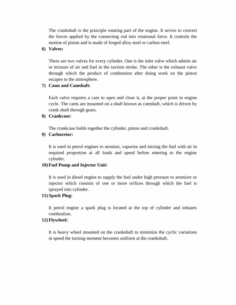
12) Flywheel:
It is heavy wheel mounted on the crankshaft to minimize the cyclic variations
in speed the turning moment becomes uniform at the crankshaft.

WORKING OF FOUR STROKE PETROL ENGINE:
Petrol Engine operates on a four stroke cycle.
I. INTAKE OR SUCTION STROKE:
During suction stroke intake valve is opened and the exhaust valve is
closed and the piston moves down, due to rotation of crankshaft either
getting energy from the flywheel or from a motor starter. As the piston
moves the pressure in the cylinder drops below atmospheric pressure.
The high pressure on carburetor or air filter side thrust the air to rush
towards cylinder. The suction process continues till the piston moves
from the top dead centre position to the bottom dead centre.
II. COMPRESSION STROKE:
During this stroke both the valve are closed and piston moves from
B.D.C to T.D.C. The air is compressed upto a compression ratio. There
is reduction of volume of air or charge which results in an increase of
pressure and the temperature of the cylinder contents. In petrol engines
the compression ratio varies from 5 to 10.5 and pressure and
temperature at the end of compression are 7 to 14 bars and 250°C to
500°C respectively. For Diesel engines the compression ratio is 12 to 20
and the pressure and temperature at the end of compression are 28 to 59
bars and 600°C to 700°C respectively.
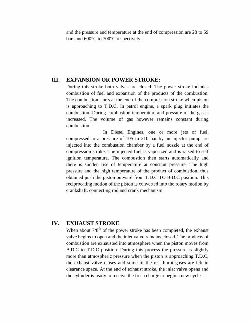
III. EXPANSION OR POWER STROKE:
During this stroke both valves are closed. The power stroke includes
combustion of fuel and expansion of the products of the combustion.
The combustion starts at the end of the compression stroke when piston
is approaching to T.D.C. In petrol engine, a spark plug initiates the
combustion. During combustion temperature and pressure of the gas is
increased. The volume of gas however remains constant during
combustion.
In Diesel Engines, one or more jets of fuel,
compressed to a pressure of 105 to 210 bar by an injector pump are
injected into the combustion chamber by a fuel nozzle at the end of
compression stroke. The injected fuel is vaporized and is raised to self
ignition temperature. The combustion then starts automatically and
there is sudden rise of temperature at constant pressure. The high
pressure and the high temperature of the product of combustion, thus
obtained push the piston outward from T.D.C TO B.D.C position. This
reciprocating motion of the piston is converted into the rotary motion by
crankshaft, connecting rod and crank mechanism.
IV. EXHAUST STROKE
When about 7/8th
of the power stroke has been completed, the exhaust
valve begins to open and the inlet valve remains closed. The products of
combustion are exhausted into atmosphere when the piston moves from
B.D.C to T.D.C position. During this process the pressure is slightly
more than atmospheric pressure when the piston is approaching T.D.C,
the exhaust valve closes and some of the rest burnt gases are left in
clearance space. At the end of exhaust stroke, the inlet valve opens and
the cylinder is ready to receive the fresh charge to begin a new cycle.
APPLICATIONS:
7. I.C Engines are used in all road vehicles
8. I.C Engines are widely used in rail road, aviation, marine etc.
9. I.C Engines are extensively used in lawn movers, motor boats,
concrete mixing equipment etc.

EXPERIMENT-4
EXPERIMENT ON CENTRIFUGAL PUMP
Learning Objectives:
At the end of this experiment, the student will be able to:
Know the operation of centrifugal pump.
Draw the characteristic curves of centrifugal pump at constant speed.
Aim: To conduct performance test on a centrifugal pump at rated speed.
Model:
Fig. Component parts of Centrifugal Pump
**

Theory: A centrifugal pump consists of an impeller rotating inside a casing .The impeller
has a number of curved vanes. Due to the centrifugal head impressed by the rotation of
the impeller, the water enter at the Centre and flows outwards to the periphery.Then it is
collected in a gradually increasing passage in the casing known as volute chamber which
serves to convert a part of the velocity head into pressured head. For a higher heads multi stage centrifugal pumps having two or more impellers in series
will have to be used. This single stage centrifugal pump of size (50mm x 50mm) is
coupled to 3 HP capacity Squirrel cage induction motor. The suction side is 50mm dia
and delivery side is 50mm dia.An energy meter is provided to measure the input to the
motor and collecting tank to measure the discharge. A pressure gauge and vacuum gauge
are fitted in delivery and suction sides to measure the head of water. The pump must be
full of water upto delivery valve before starting. For this reason it should not be allowed
water to drain and hence a foot valve is provided. But after the long run the leather valve
in the foot valve becomes useless and so the foot valve becomes leaky.In this case the pump
should be primed by pouring water.
Tools required: Stop watch, measuring scale and Energy meter etc.
Procedure:
1. Check the pressure gauges. Make sure both of them show atmospheric pressure. 2. Observe the suction and delivery pipe diameters. Measure the dimensions of
collecting tank. Measure the difference in elevation between the suction and delivery pressure tapings.
3. Prime the centrifugal pump. Keep the delivery valve fully closed.
4. Start the pump.
5. Open the delivery valve slightly. Observe the pressure gauge readings.
6. Measure the discharge using the collecting tank stopwatch setup.
7. Note the time for n revolutions of the energy meter disk. 8. Open the delivery valve gradually to maximum. Repeat the above observations
for different discharges. 9. Tabulate the readings. Draw the performance characteristics; H Vs. Q, Pbhp
10. Vs. Q and h Vs. Q.
Observations:
1. Size of the collecting tank = l b h
2. Diameter of the suction pipe, ds = 50 mm
3. Diameter of the delivery pipe, dd = 50 mm 4. Energy meter constant, N = 400 rev / KWH
**

5. Difference in the levels of pressure and vacuum gauges, X = 43cm.
Model Calculations:
1. Actual discharge : Q = AR/t (m3/s)
Where
A: Cross-sectional area of collecting tank = l b R: Rise of water column in collecting tank in meters
t: Time taken for ‘R’ units rise of water column in seconds
Q = m3/s
2. Pressure gauge reading in metres of water column (Hg)
Hg = (Pg 104 9.81)/ 9810 m
Pg = Pressure gauge reading in kg/cm2
Hg =
3. Vacuum gauge reading in meters of water column (Hv)
Hv = (hv 10-3
x 13.6) m of water
Hv = Vacuum gauge reading
4. Velocity head in delivery pipe (Vd2 / 2g)
Vd : Velocity of flow in delivery pipe = Q/(/4 dd2)
(Vd2 / 2g) =
5. Velocity head in suction pipe (Vs2/ 2g)
Vs : Velocity of flow in suction pipe = Q/(/4ds2)
(V2s / 2g) =
6. Total head in the pump (H)
H : Hg + Hv + X
7. Output of the pump (O/P)
Out Put = .Q.H Watts
8. Input to the pump (I/P)
I/P = (3600 n) / (N T)
7

n : Number of revolutions of energy meter
N : Energy meter constant rev/ kWh
T : Time for ‘n’ revolutions of energy meter in sec.
9. Overall efficiency (o)
o = Output/Input Observation Table Graph: H Vs Q at constant speed
Q/p Vs Q at constant speed
I/p Vs Q at constant speed Vs Q at constant speed
Result:
Review Questions:
1. What is priming? What is use of foot valve?
2. What is manometric head?
3. What is the function of the casing used in centrifugal pump?
4. What is NPSH?
5. What is the minimum starting speed of a centrifugal pump?
6. Hydraulic efficiency of centrifugal pump is defined as. 7. The centrifugal pump should be so installed above the water level in the sump
why?

EXPERIMENT-5
EXPERIMENT ON RECIPROCATING PUMP
Learning Objectives:: At the end of this experiment, the student will be able to:
Know the operation of reciprocating pump.
Draw the characteristic curves of reciprocating pump.
Aim: To determine the efficiency of reciprocating pump at a constant speed.
Model:
Fig. Reciprocating pump with air vessel Principle: Reciprocating pump is a positive displacement pump, which causes a fluid to move by trapping a fixed amount of it then displacing that trapped volume into the discharge pipe. The fluid enters a pumping chamber via an inlet valve and is pushed out via a outlet valve by the action of the piston or diaphragm. They are either single acting; independent suction and discharge strokes or double acting; suction and discharge in both directions. Reciprocating
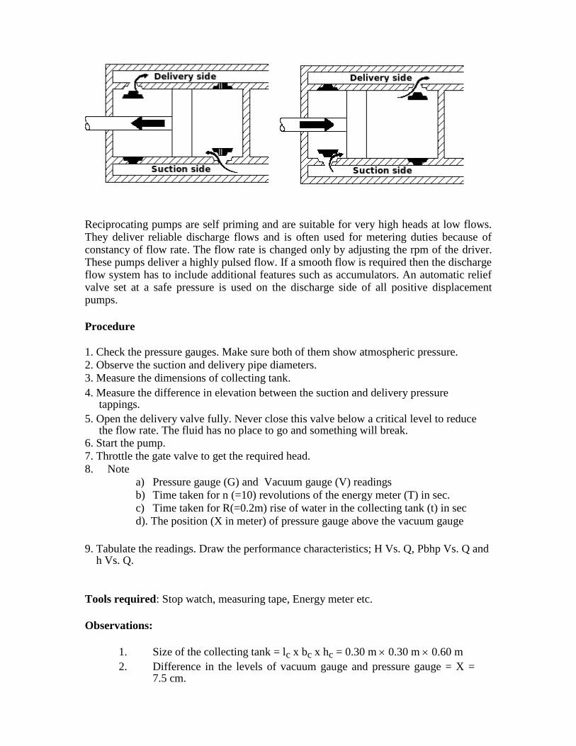
Reciprocating pumps are self priming and are suitable for very high heads at low flows. They deliver reliable discharge flows and is often used for metering duties because of constancy of flow rate. The flow rate is changed only by adjusting the rpm of the driver. These pumps deliver a highly pulsed flow. If a smooth flow is required then the discharge flow system has to include additional features such as accumulators. An automatic relief valve set at a safe pressure is used on the discharge side of all positive displacement pumps.
Procedure 1. Check the pressure gauges. Make sure both of them show atmospheric pressure.
2. Observe the suction and delivery pipe diameters.
3. Measure the dimensions of collecting tank. 4. Measure the difference in elevation between the suction and delivery pressure
tappings. 5. Open the delivery valve fully. Never close this valve below a critical level to reduce
the flow rate. The fluid has no place to go and something will break. 6. Start the pump.
7. Throttle the gate valve to get the required head.
8. Note
a) Pressure gauge (G) and Vacuum gauge (V) readings
b) Time taken for n (=10) revolutions of the energy meter (T) in sec.
c) Time taken for R(=0.2m) rise of water in the collecting tank (t) in sec
d). The position (X in meter) of pressure gauge above the vacuum gauge
9. Tabulate the readings. Draw the performance characteristics; H Vs. Q, Pbhp Vs. Q and
h Vs. Q.
Tools required: Stop watch, measuring tape, Energy meter etc.
Observations:
1. Size of the collecting tank = lc x bc x hc = 0.30 m 0.30 m 0.60 m
2. Difference in the levels of vacuum gauge and pressure gauge = X = 7.5 cm.

3. Energy meter constant, N = 800 rev/kwh
Model Calculations:
1. Actual discharge Q = AR/t m3/s
A: Cross-sectional area of collecting tank = 1c bc (0.30 m 0.30 m) R: Rise of water column in collecting tank t: Time taken for ‘R’ units rise of water column
2. Pressure gauge reading in water (Hg
meters) Pg = W. Hg
Therefore Hg = Pg / W = Pg 104 9.81
------------------- m 9810
Where PG = Pressure gauge reading in Kg/cm2
3. Vacuum gauge reading in water (Hv meters )
Pv = W. Hv
Pv 104 9.81
Therefore Hv = Pv /W = ------------------ m
9810 Where
Pv = Vacuum gauge reading in Kg/Cm2
4. Velocity head in the suction pipe (Vs2 / 2g)
Where Vs: Velocity of flow in suction pipe = Q/As = Q / (/4ds2)
5. Velocity head in the delivery pipe (Vd2 / 2g)
Where Vd: Velocity of flow in delivery pipe = Q/Ad = Q / (/4 dd2)
6. Total head on the pump (H)
H = Hg + Hv + (Vd2 / 2g - Vs
2 / 2g ) + X
7. Output from the pump (O/P)
O/P = W. Q. H Watts
Where W: Specific weight of liquid being pumped = 9810
N/m3 Q: Actual Discharge
H: Total Head on the pump
Input to the pump (I/P)
I/P = 3600 n/NT

N T
Where n: Number of revolutions of the energy meter
N: Energy meter constant (rev/kWh)
T: Time taken for ‘n’ revolutions of energy meter
9. Overall efficiency of the pump ( )
=IP/OP *100
Observation Table
Sl Press.Gauge Vacuum Height Total Time for Time Actual Out Input Effi-
No Readings Gauge of Head 0.2 m for 10 Disch- put kw ciency
Readings Pressure ‘h’ rise in rev. in arge kw
gauge in m collecting energy Qa in
above tank meter T m3/S
vacuum T seconds
gauges seconds
(x .m.)
1
2
3
4
Graph: See page No.1122 of FM & HM by Modi & Seth for
operating characteristics curves
Also for fig see page No.1094 of the above text book
Result:
**

EXPERIMENT 6
TURBINE EXPERIMEENT ON PELTON WHEEL
Learning Objectives: At the end of this experiment, the student will be able to: e
Know the working of a Pelton wheel.
Draw the characteristic curves of Pelton turbine under constant head and constant speed.
Aim: To determine the characteristic curves of Peloton wheel under constant
head and constant speed.
Model: Stop watch and measured weights etc.

Tools required: Pelton Turbine, Pressure gauges, Tachometer and
Manometer
Procedure for constant speed:
1. Keeps the nozzle opening at the required position i.e. full opening or 3/4th
opening?
2. Start the pump
3. Allow water to the turbine, then the turbine rotates
4. Adjust the gate valve such that the required head is achieved.
5. Note the speed of the turbine
6. Take readings in manometer
7. Note down the pressure of water in the pressure gauge
8. Load the turbine by putting weights.
9. Note down the dead weight T1 and spring weight T2 10. Note down the head. 11. Repeat the experiment for different loadings
12. Tabulate the readings
Procedure for variable speed:
1. Fix the guide vane opening as 4/8
2. Prime the pump
3. Allow water into turbine by starting the pump
4. Vent the cocks of manometer 5. Allow the water into the runner such that the speed of the turbine runner is at
required constant speed using tachometer. 6. Note down the readings of left limb and right limb of differential manometer
7. Note down the pressure gauge reading
8. Note down the spring weight and dead weight on the hanger
9. Add weight to the hanger of brake drum and repeat the steps from 5 to 8.
10. Repeat the experiment steps from 5 to 10 for different guide vane openings.
Observations:
To find discharge the venturimeter and the manometer have been calibrated.
Venturimeter: d/D = 0.6, D = 0.065 m, Q a = 0.0055√ H1 m3/s
The height of mercury column in left arm = h1 m
The height of mercury column in right arm = h2 m
Difference of levels = h1 – h2 = h
Equivalent water column = (Sm/S –1)h = (13.6/1-1)h = 12.6h = H1
Model Calculations:
1. Calculation of IP:
Discharge = Q m3/s
Head = H m
IP = QH
**

2. Calculation of BP:
Dead weight (T1) = Kg
Spring weight (T2) = Kg Weight of hanger (To) = Kg
Resultant load (T) =T1-T2+To = Kg Speed (N) = rpm Dia. of brake drum = 0.40 m
Thickness of rope = 0.015 m.
Resultant dia., D = 0.415 m
BP = 2NT/60
3. Efficiency of the turbine, η = BP
IP
Observation Table
Sl.No. Head Manometer Discharge Speed T1 T2 T BP IP Efficiency
(m) (h) m m3/s rpm
Result:
Review Questions:
1. What are main components of Pelton turbine?
2. Draw velocity diagrams (at inlet and outlet) for Pelton blade
3. Why is Pelton turbine suitable for high heads?
4. What is the function of spear mechanism?
5. What is the normal range of specific speed of a Pelton turbine
6. What are the characteristics of Pelton wheel? What are their uses?
7. After the nozzle water has atmospheric pressure through out, then why is a
casing provided to the wheel?
8. Why not Pelton wheels are suitable for low heads?
9. What are the methods available to govern the turbine?

EXPERIMENT 7
TURBINE EXPERIMEENT ON FRANCIS TURBINE
Learning Objectives: At the end of this experiment, the student will be able to:
Know the working of a Francis turbine.
Draw the characteristic curves of Francis turbine. Aim: a) To study the constant head characteristics of Francis turbine
b) To study the operating characteristics of Francis turbine.
c) To determine the specific speed
Model:
Fig. Francis Turbine
Tools required: Francis Turbine, Pressure gauges, Tachometer and

Manometer
Procedure for constant head operation of turbine:
1. Fix the guide vane opening as 4/8.
2. Prime the pump
3. Allow water in the turbine by starting the pump
4. Vent the cocks of manometer 5. Adjust the gate valve such that the sum of the pressure gauge and vacuum
gauge is as required constant head. 6. Note down the pressure gauge and vacuum gauge readings.
7. Note down the left limb and right limb of the differential manometer.
8. Note down the spring weight and dead weight on hanger.
9. Measure the speed of the turbine using tachometer.
10. Repeat the experiment by adding loads on the brake drum
11. Repeat the steps from 1 to 10 for different guide vane opening.
Procedure for variable speed head operation of turbine:
1. Fix the guide vane opening as 4/8.
2. Prime the pump
3. Allow water into turbine by starting the pump
4. Vent the cocks of manometer. 5. Allow the water into the runner such that the speed of the turbine runner is at
required constant speed using tachometer.
6. Note down the left limb and right limb of differential manometer.
7. Note down the pressure gauge and vacuum gauge readings.
8. Note down the spring weight and dead weight on the hanger.
9. Add weight to the hanger of brake drum repeat the steps from 5 to 8.
10. Repeat the experiment steps from 5 to 9 for different guide vane openings.
Model Calculations:
a) Discharge formula for venturimeter Q=0.031√H1
Where H1=12.6h.
h = difference in the levels of manometer.
b) Total head H = G+V
Where G= pressure head
V=Vaccum head
c) Input to the turbine IP = Q H
d) Output

Brake drum diameter = 0.3 m
Pipe diameter = 0.015 m.
Equivalent drum diameter = 0.315 m
Hanger weight To= 1 kg.
Load weight = T1 kg.
Spring weight = T2 Kg.
Resultant load T= (T1+T0-T2) kg. Speed of turbine = N rpm. BP = 2 NT/60
e) Efficiency (o) = Output = BHP Input IHP
f) Specific speed: It may be defined as the speed of geometrically similar
turbine which will develop one unit power under unit head.
Ns = N √P
H5/4
Result:
Review Questions:
1. What is the function of draft tube?
2. What is the function of guide vanes?
3. Can you locate the portion in Francis turbine where cavitations likely to
occur?
4. What is the advantage of draft tube divergent over a cylindrical of uniform
diameter along its length?
5. What are fast, medium by slow runners?

EXPERIMENT 8
TURBINE EXPERIMEENT ONKAPLAN TURBINE Learning Objectives: At the end of this experiment, the student will be able to:
Know the working of a Kaplan turbine.
Draw the characteristic curves of Kaplan turbine.
Aim: To draw the performance characteristic curves and determine the overall efficiency.
Model:
Fig. Kaplan Turbine
Tools required: Kaplan Turbine, Pressure gauges, Tachometer and
Manometer
Procedure:
1. Keep the guide vane at 2/8 opening
2. Keep the runner vane at 3/8 opening
3. Prime the pump and close the gate valve
4. Start the pump
5. Open the gate valve slowly
6. Note down the pressure gauge reading G.
7. Note down the vacuum gauge reading V.
8. Vent the gauges of venturimeter
9. Note down the readings of pressure gauge (G1) and vacuum gauge (V1) 10. Measure the speed of the turbine by tachometer. 11. Load the turbine by placing dead weight and take all readings. 12. Experiment can be repeated for different guide and runner vane openings.
**

Observations:
Hanger weight (T0) =
Brake drum resultant dia. =
Model Calculations:
1. Discharge equation of venturimeter Q= 0.082H1 m3/sec.
Where H1= (G1+V1) m
2. Head: H = G + V
Where G= Pressure gauge reading in meters
V= Vacuum gauge reading in meters.
3. Input to the turbine IP = QH
4. Output:
Brake drum diameter = 0.30 m.
Rope diameter = 0.015 m Equivalent drum diameter D = 0.315 m
Dead weight T1=
Hanger weight To =
Spring weight T2 =
Resultant load T =T1-T2+To = Speed of the turbine N = BP = 2NT/60 =
5. Efficiency = Output /Input = BP/IP
Observation Table:
Sl. Guide Gauge reading of Gauge reading of Spring Dead Speed
No and venturimeter kaplan turbine weight weight runner
runner
T1 T2 N
G1 V1 G2 V2
vane (Kg/m2) (Kg/m
2) (Kg/m
2) (Kg/m
2) (rpm)
opening
1
2
3
4
5
**

Graphs:
1) % of full load Vs o
2) N u Vs Q u or Pu or o
Result:
Review Questions:
1. What are suitable conditions for erection of Kaplan turbine
2. Why is the number of blades of Kaplan turbine restricted to 4 to 6?
3. Is this turbine axial flow or mixed flow?
4. Port load efficiency of Kaplan turbine is high, why?
5. What is the minimum pressure that can be maintained at the exit of the reaction
turbine?

EXPERMENT 9
IMPACT OF JET EXPERIMENT
Learning Objectives:
At the end of this experiment, the student will be able to:
Derive the expression for impact of jet on flat and hemispherical plates.
Calculate the co-efficient of impact.
Aim: To find the co-efficient of impact (C i) for flat and hemi
spherical plates.
Tools required: Experimental setup of impact of jet with flat and
Hemispherical plates set of weights, stop watch and scale.
Procedure:
1. The lever is kept horizontal by adjusting counter weight on the left hand side
weigh the plate is fixed opposite to the jet. 2. A weight of 100gm is placed on the right hand side pan.
3. Water is jet is allowed to strike plate and discharge is so adjusted
4. The lever retains equilibrium position.
5. The pressure gauge reading is noted and time taken for H cm rise in
6. The collecting tank is also noted.
7. The weight on the right hand side pan is increased and procedure
8. Repeated for five such different weights.
9. Then the plate is changed and another plate is fixed and the whole
10. Experiment is repeated.
Model Calculations:
Fact = W Y/X
Y = X =
F t h = PQV
Q = AH/t m3/sec.
V = Velocity of jet
= √ 2g x (p/γ –z)
Where γ = 9.81 x 10³ N/m
3
ρ = Z =
C i = Fact /Ft h

Observation Table:
Graph:
Q a Vs. C i for flat and hemi spherical plates
Result:
Co-efficient of impact for
Flat plate =
Hemi spherical plate =
Review Questions:
1. What is an expression for impact of jet on fixed flat plate?
2. What is an expression for impact of jet on moveable flat plate? 3. What is an expression for impact of jet on fixed inclined plate? 4. What is an expression for impact of jet on fixed curved plate?

![49242764 Hydraulic Machines Textbook[1]](https://static.fdocuments.net/doc/165x107/5453ec4fb1af9f14058b4b92/49242764-hydraulic-machines-textbook1.jpg)