THERM+ H-I/H-V TC timber connector Static dimensioning … · 6 2015 THERM+ TC timber connector...
22
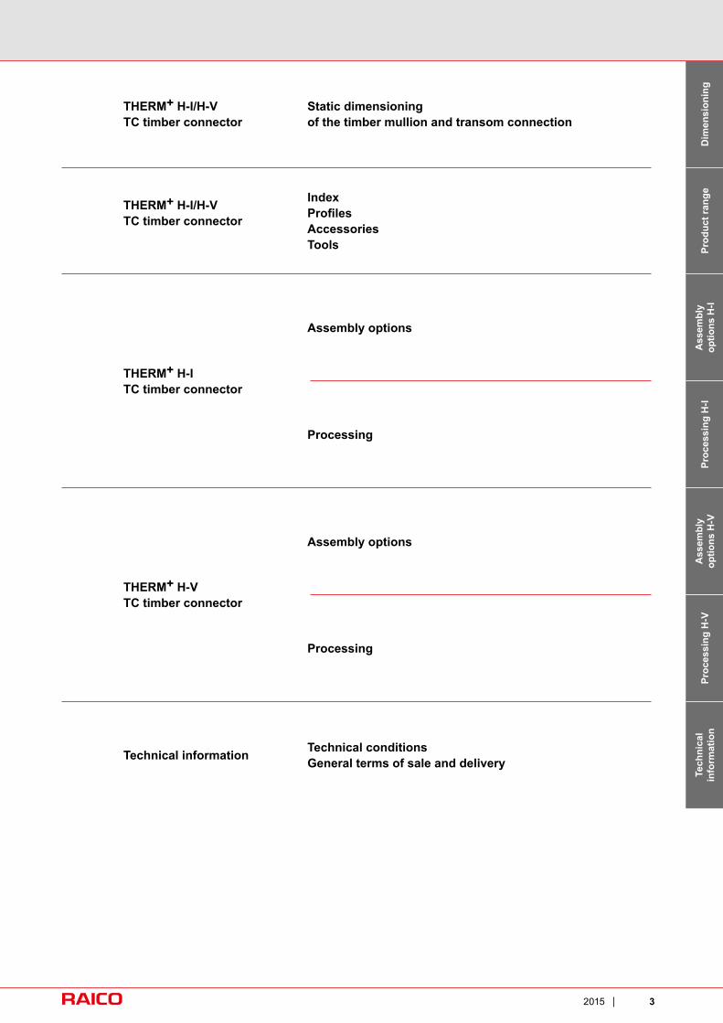
3 2015 Assembly options THERM + H-I TC timber connector Processing Assembly options Technical conditions General terms of sale and delivery Technical information Technical information Assembly options H-V Processing H-I Assembly options H-I Static dimensioning of the timber mullion and transom connection THERM + H-I/H-V TC timber connector Index Profiles Accessories Tools THERM + H-I/H-V TC timber connector Product range Dimensioning THERM + H-V TC timber connector Processing Processing H-V
-
Upload
duongkhanh -
Category
Documents
-
view
226 -
download
1
Transcript of THERM+ H-I/H-V TC timber connector Static dimensioning … · 6 2015 THERM+ TC timber connector...
32015
Assembly options
THERM+ H-ITC timber connector
Processing
Assembly options
Technical conditions General terms of sale and delivery Technical information
Tech
nica
lin
form
atio
nA
ssem
bly
optio
ns H
-VPr
oces
sing
H-I
Ass
embl
yop
tions
H-I
Static dimensioning of the timber mullion and transom connection
THERM+ H-I/H-VTC timber connector
IndexProfi lesAccessoriesTools
THERM+ H-I/H-VTC timber connector
Prod
uct r
ange
Dim
ensi
onin
g
THERM+ H-VTC timber connector
Processing
Proc
essi
ng H
-V

4 2015

52015
THERM+ TC timber connectorSystem benefi ts
Timber curtain wall 50/56/76/96 mmTechnology in detail
■ Technical information – The mullion and transom connection is extremely
important for the quality and structural stability of a glass façade.The glass loads on the timber structure and the resulting torsion forces in the transom must be safely dispersed and reliably transferred to the supporting structure, taking into account wind pressure- and wind suction loads. The RAICO timber connector system – invisible when installed – has been particularly developed for these requirements.
– The basic SOLO version consists of three compo-nents which are screwed laterally to the mullions and to the front face of the transoms. They are secured after fitting the transom with special nail screws.
– All timber connector variants are assembled with minimal effort and in simple steps. The integrated longitudinal stop and the transom contact pressure over the entire length produce a perfect T-connection.
– The European Technical Approval (ETA)-tested SOLO and KOMBI RAICO connectors provide the right solution for all timber and glass façades.
– Tested at infi ll thicknesses of up to 64 mm. – Straightforward and simple to install. – Simplifi ed connection to the transom.

6 2015
THERM+ TC timber connectorSystem benefi ts
Timber curtain wall 50/56/76/96 mmVariants
■ SOLO – Tensioned with nail screws. – Safe and tested dispersal of glass weights. – Inserted invisibly between mullion and transom. – Tested according to ETA-13/0765. – Safe dispersal of the glass loads and resulting
torsion forces via the timber structure. – Seven installation depths for transom depths from
60 to 300 mm. – Installation in a few simple steps and minimum
processing. – Integrated longitudinal stop and transom contact pres-
sure over the entire depth for a perfect T-connection.
■ KOMBI – Tensioned with nail screws through the transom
base profile. – Safe and tested dispersal of glass weights. – Inserted invisibly between mullion and transom. – Tested according to ETA-13/0765. – Safe dispersal of the glass loads and resulting
torsion forces via the timber structure. – Seven installation depths for transom depths from
60 to 300 mm. – Installation in a few simple steps and minimum
processing. – Integrated longitudinal stop and transom contact pres-
sure over the entire depth for a perfect T-connection.
■ Super-simple installation – Highly efficient and time-saving. – All machining is in transoms. – Few special screws required for maximum
load-bearing capacity. – Stable connection for high glass loads. – Extremely fast construction site assembly:
Push in transoms and screw together. – Transoms can be dismantled at any time. – No adjustment needed thanks to the
automatically flush stop.

72015
THERM+ TC timber connectorSystem benefi ts
Timber curtain wall 50/56/76/96 mmVariants
■ High loading capacity on european standard The new timber connector is tested according to the current guideline ETAG 015 and certified with the european technical approval
ETA-13/0765. In comparison to the previous timber connector now the infill thickness of 64 mm is tested and also part of the afore-mentioned approval. Due to detail improvements the new timber connector which is available in the versions SOLO and KOMBI characterises a much more rational and technical superior assembly.
– Static calculation possible on the base of the Eurocodes. – The denoted loads of the connector are based on a minimum apparent density of 350 kg/m³, with the use of timber or derived
timber products with a higher apparent density the loads can be increase up to an apparent density of 500 kg/m³.
Admissible loads in consideration of the apparent density TC SOLO
Apparent density
Type of connector
350 kg/m3 380 kg/m3 400 kg/m3 450 kg/m3 500 kg/m3
Maximum glass load* per transom in kg*it is imperative to respect the ETA-13/0765
TC 60 SOLO 116 119 120 124 126TC 80 SOLO 138 141 143 147 151
TC 100 SOLO 162 167 170 176 182
TC 120 SOLO 182 188 191 198 205TC 160 SOLO 218 225 229 239 248TC 200 SOLO 250 258 263 274 286TC 240 SOLO 276 285 291 305 317
Admissible loads in consideration of the apparent density TC KOMBI
Apparent density
Type of connector
350 kg/m3 380 kg/m3 400 kg/m3 450 kg/m3 500 kg/m3
Maximum glass load* per transom in kg*it is imperative to respect the ETA-13/0765
TC 60 KOMBI 253 256 257 260 263TC 80 KOMBI 274 278 279 284 288
TC 100 KOMBI 367 372 375 381 387
TC 120 KOMBI 388 393 396 403 410TC 160 KOMBI 423 430 434 444 453TC 200 KOMBI 455 463 468 480 491TC 240 KOMBI 481 490 496 510 523

8 2015
THERM+ TC timber connectorSystem benefi ts
Timber curtain wall 50/56/76/96 mmProfi le overview
■ Pressure and cover profi les for façades and roofs
– Extensive range of shapes for all system widths.
– Individual project solutions available in short time-scales.
– Particularly attractive flat pressure profile with just 4 mm glass overlap.
– Special accessory for optimum sealingof intersection point.
– Clip-on timber cover profile available.
■ Base profi les – To fit all system variants. – Improved screw channel for optimised
thermal insulation. – Special seal holder for easy insertion
of silicon-free EPDM internal seal. – Punched slot for integrated expansion
compensation. – With or without foot.
92015
THERM+ TC timber connectorSystem benefi ts
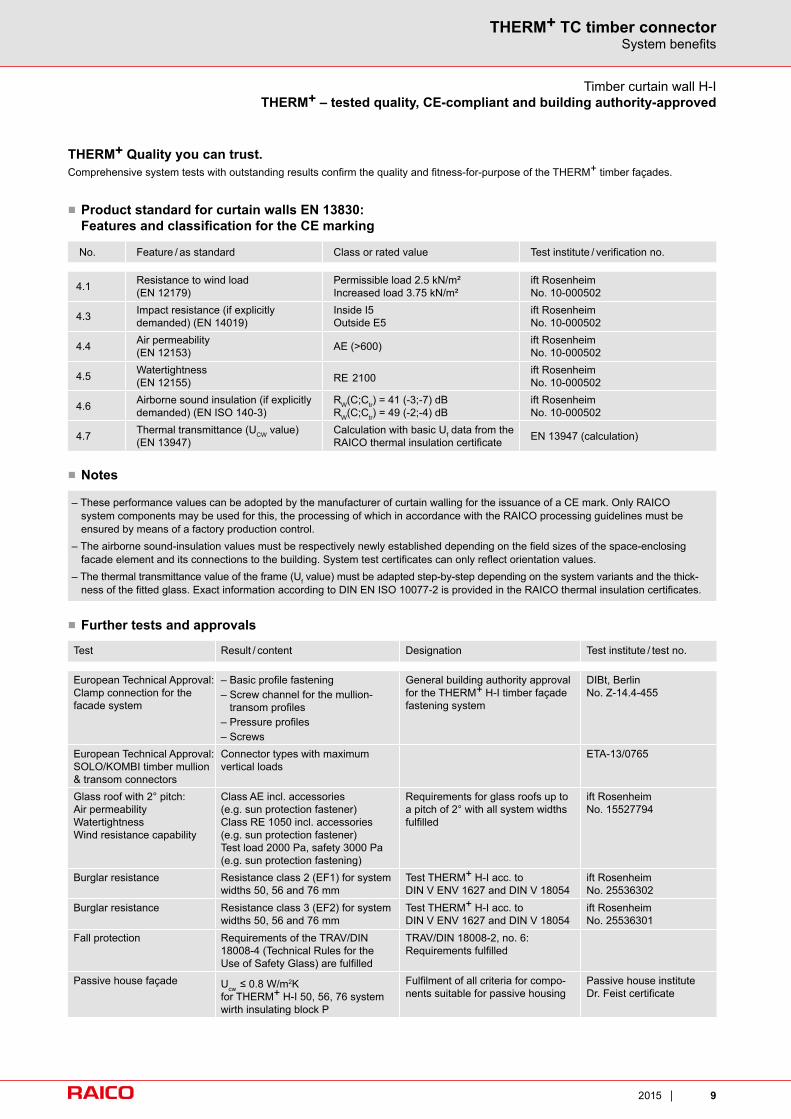
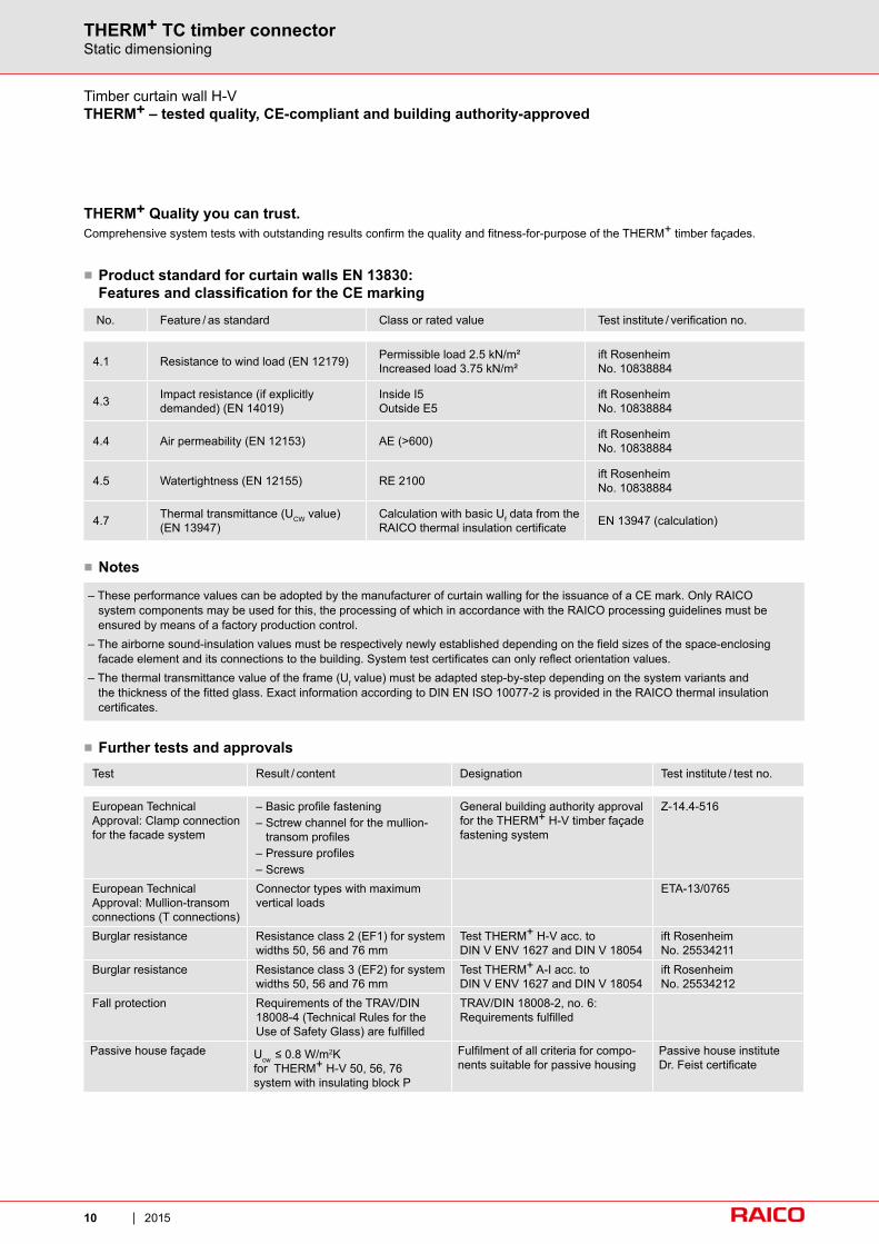
– These performance values can be adopted by the manufacturer of curtain walling for the issuance of a CE mark. Only RAICO system components may be used for this, the processing of which in accordance with the RAICO processing guidelines must be ensured by means of a factory production control.
– The airborne sound-insulation values must be respectively newly established depending on the field sizes of the space-enclosing facade element and its connections to the building. System test certificates can only reflect orientation values.
– The thermal transmittance value of the frame (Uf value) must be adapted step-by-step depending on the system variants and the thick-ness of the fitted glass. Exact information according to DIN EN ISO 10077-2 is provided in the RAICO thermal insulation certificates.
■ Notes
■ Product standard for curtain walls EN 13830: Features and classifi cation for the CE marking
No. Feature / as standard Class or rated value Test institute / verification no.
4.1 Resistance to wind load (EN 12179)
Permissible load 2.5 kN/m²Increased load 3.75 kN/m²
ift RosenheimNo. 10-000502
4.3 Impact resistance (if explicitly demanded) (EN 14019)
Inside I5Outside E5
ift RosenheimNo. 10-000502
4.4 Air permeability (EN 12153) AE (>600) ift Rosenheim
No. 10-000502
4.5 Watertightness (EN 12155) RE 2100
ift RosenheimNo. 10-000502
4.6 Airborne sound insulation (if explicitly demanded) (EN ISO 140-3)
RW(C;Ctr) = 41 (-3;-7) dBRW(C;Ctr) = 49 (-2;-4) dB
ift RosenheimNo. 10-000502
4.7 Thermal transmittance (UCW value)(EN 13947)
Calculation with basic Uf data from the RAICO thermal insulation certificate EN 13947 (calculation)
Test Result / content Designation Test institute / test no.
European Technical Approval:Clamp connection for the facade system
– Basic profile fastening– Screw channel for the mullion-
transom profiles– Pressure profiles– Screws
General building authority approval for the THERM+ H-I timber façade fastening system
DIBt, BerlinNo. Z-14.4-455
European Technical Approval:SOLO/KOMBI timber mullion & transom connectors
Connector types with maximum vertical loads
ETA-13/0765
Glass roof with 2° pitch:Air permeabilityWatertightnessWind resistance capability
Class AE incl. accessories(e.g. sun protection fastener)Class RE 1050 incl. accessories(e.g. sun protection fastener)Test load 2000 Pa, safety 3000 Pa (e.g. sun protection fastening)
Requirements for glass roofs up to a pitch of 2° with all system widths fulfilled
ift RosenheimNo. 15527794
Burglar resistance Resistance class 2 (EF1) for system widths 50, 56 and 76 mm
Test THERM+ H-I acc. toDIN V ENV 1627 and DIN V 18054
ift RosenheimNo. 25536302
Burglar resistance Resistance class 3 (EF2) for system widths 50, 56 and 76 mm
Test THERM+ H-I acc. toDIN V ENV 1627 and DIN V 18054
ift Rosenheim No. 25536301
Fall protection Requirements of the TRAV/DIN 18008-4 (Technical Rules for the Use of Safety Glass) are fulfilled
TRAV/DIN 18008-2, no. 6:Requirements fulfilled
Passive house façade Ucw ≤ 0.8 W/m2K for THERM+ H-I 50, 56, 76 systemwirth insulating block P
Fulfilment of all criteria for compo-nents suitable for passive housing
Passive house institute Dr. Feist certificate
■ Further tests and approvals
THERM+ Quality you can trust.Comprehensive system tests with outstanding results confirm the quality and fitness-for-purpose of the THERM+ timber façades.
Timber curtain wall H-ITHERM+ – tested quality, CE-compliant and building authority-approved
10 2015
THERM+ TC timber connectorStatic dimensioning
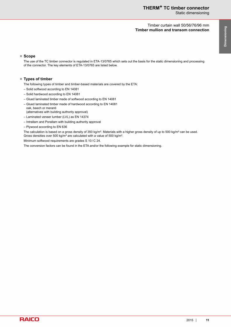
– These performance values can be adopted by the manufacturer of curtain walling for the issuance of a CE mark. Only RAICO system components may be used for this, the processing of which in accordance with the RAICO processing guidelines must be ensured by means of a factory production control.
– The airborne sound-insulation values must be respectively newly established depending on the field sizes of the space-enclosing facade element and its connections to the building. System test certificates can only reflect orientation values.
– The thermal transmittance value of the frame (Uf value) must be adapted step-by-step depending on the system variants and the thickness of the fitted glass. Exact information according to DIN EN ISO 10077-2 is provided in the RAICO thermal insulation certificates.
■ Notes
■ Product standard for curtain walls EN 13830:Features and classifi cation for the CE marking
No. Feature / as standard Class or rated value Test institute / verification no.
4.1 Resistance to wind load (EN 12179) Permissible load 2.5 kN/m²Increased load 3.75 kN/m²
ift RosenheimNo. 10838884
4.3 Impact resistance (if explicitly demanded) (EN 14019)
Inside I5Outside E5
ift RosenheimNo. 10838884
4.4 Air permeability (EN 12153) AE (>600) ift RosenheimNo. 10838884
4.5 Watertightness (EN 12155) RE 2100 ift RosenheimNo. 10838884
4.7 Thermal transmittance (UCW value)(EN 13947)
Calculation with basic Uf data from the RAICO thermal insulation certificate EN 13947 (calculation)
Test Result / content Designation Test institute / test no.
European Technical Approval: Clamp connection for the facade system
– Basic profile fastening– Sctrew channel for the mullion-
transom profiles– Pressure profiles– Screws
General building authority approval for the THERM+ H-V timber façade fastening system
Z-14.4-516
European Technical Approval: Mullion-transom connections (T connections)
Connector types with maximum vertical loads
ETA-13/0765
Burglar resistance Resistance class 2 (EF1) for system widths 50, 56 and 76 mm
Test THERM+ H-V acc. toDIN V ENV 1627 and DIN V 18054
ift RosenheimNo. 25534211
Burglar resistance Resistance class 3 (EF2) for system widths 50, 56 and 76 mm
Test THERM+ A-I acc. toDIN V ENV 1627 and DIN V 18054
ift Rosenheim No. 25534212
Fall protection Requirements of the TRAV/DIN 18008-4 (Technical Rules for the Use of Safety Glass) are fulfilled
TRAV/DIN 18008-2, no. 6:Requirements fulfilled
Passive house façade Ucw ≤ 0.8 W/m2K for THERM+ H-V 50, 56, 76 system with insulating block P
Fulfilment of all criteria for compo-nents suitable for passive housing
Passive house institute Dr. Feist certificate
■ Further tests and approvals
THERM+ Quality you can trust.Comprehensive system tests with outstanding results confirm the quality and fitness-for-purpose of the THERM+ timber façades.
Timber curtain wall H-VTHERM+ – tested quality, CE-compliant and building authority-approved
112015
THERM+ TC timber connectorStatic dimensioning
Dim
ensi
onin
g
■ Scope The use of the TC timber connector is regulated in ETA-13/0765 which sets out the basis for the static dimensioning and processing
of the connector. The key elements of ETA-13/0765 are listed below.
■ Types of timber The following types of timber and timber-based materials are covered by the ETA: – Solid softwood according to EN 14081 – Solid hardwood according to EN 14081 – Glued laminated timber made of softwood according to EN 14081 – Glued laminated timber made of hardwood according to EN 14081
oak, beech or meranti (alternatives with building authority approval)
– Laminated veneer lumber (LVL) as EN 14374 – Intrallam and Porallam with building authority approval – Plywood according to EN 636 The calculation is based on a gross density of 350 kg/m³. Materials with a higher gross density of up to 500 kg/m³ can be used.
Gross densities over 500 kg/m³ are calculated with a value of 500 kg/m³. Minimum softwood requirements are grades S 10 / C 24. The conversion factors can be found in the ETA and/or the following example for static dimensioning.
Timber curtain wall 50/56/76/96 mmTimber mullion and transom connection

12 2015
THERM+ TC timber connectorStatic dimensioning
■ Services classesThe RAICO TC timber connector can only be used in buildings in the service classes 1 + 2 according to Eurocode 5. These categories are differentiated as follows:
Timber curtain wall 50/56/76/96 mmTimber mullion and transom connection
Table NA.6 – equilibrium moisture content of timber structural materialsExtract from DIN-EN 1995-1-1/NA:2010-12
Service class 1 2 3Equilibrium moisture content (5 to 15) %a (10 to 20) %b (12 to 24) %c
a In most softwoods in service class 1 the average equilibrium moisture content does not exceed 12 %.b In most softwoods in service class 2 the average equilibrium moisture content does not exceed 20 %.c Service class 3 also includes structures in which higher equilibrium moisture contents are permitted.
Table 1-15 Service classes (NKL) according to DIN 1052: 2008-12, 7.1.1.1)
Extract from DIN 1052
Service class
Moisture content in timber construction ma-terials, corresponds to an ambient climate of
Timber moisture w in timber construction
materials after a period of acclimatisation
Examples of ambient climate
1 T = 20° Cφ = 65 % 2) Up to around 12 % 3) all-round enclosed and
heated structures
2 T = 20° Cφ = 85 % 2) Up to around 20 % 3) roofed, open structures
3
Climatic conditions which lead to greater timber moistures than service
class 2
around > 20 % Outdoor structures exposed to the weather
1) Equilibrium moisture content of timber construction materials, see Tables 1 – 18.2) Relative humidities which are exceeded for only a few weeks per year.3) In most softwoods in this service class, the specifi ed timber moistures as average equilibrium moistures
are not exceeded.

132015
THERM+ TC timber connectorStatic dimensioning
Dim
ensi
onin
gTimber curtain wall 50/56/76/96 mmTimber mullion and transom connection
■ Dimensioning concept according to EUROCODEMullion and transom façades are dimensioned according to– EUROCODE 0 – Basis of structural design– EUROCODE 1 – Effect on structures– EUROCODE 5 – Design, calculation and dimensioning of timber buildings– EN 13830 – Product standard for curtain wall façades
(This standard regulates the deflection limits for mullion and transom components of façades)
Dimensioning is carried out according to the semi-probabilistic safety concept which substitutes admissible values with characteristic values and specifies different partial safety factors as fixed values. The mullion and transom components are dimensioned in accordance with the EUROCODES in this concept.The TC timber connectors from RAICO Bautechnik, have– reduced edge distances– end-grain screw fasteners– custom components and so fall into the standard category of "non-regulated components". Regulation is according to ETA-13/0765 dated 25.06.2013. This ETA rules the usability and load-bearing capacity of the T-connector in the following loading directions:
■ Description of the loads / direction of the loadF45 = inherent weight load caused by a filling element such as glass or metal panel. With average force transmission the tested clamping thickness is max. 65 mm. In the case of asymmetric force transmission this clamping thickness should be reduced. Please get in contact with us to discussF1 = centric tensile load on the transom. This can result from
– wind load in the region of corner glazing– replacement of mullions and continuous transoms.
In this case the corresponding proportion of the glass load of the adjacent fields is considered.F2, F3 = right-angled load on mullion- and transom axis. Loads in this direction can be e.g.
– Wind suction loads– Wind pressure loads– Balustrade loads
ETA-13/0765 breaks down the directions of loads as follows:
F2 = load in the wind pressure direction
F3 = load in the wind suction direction

14 2015
THERM+ TC timber connectorStatic dimensioning
Please note:The basis for structural dimensioning is always the European Technical Approval.– ETA-13/0765– EUROCODES 0, 1, 5 as well as national appendices– Product standard EN 13830 for curtain wall façades– Requirements from the structure– the national appendices the Eurocodes and/or
national regulations must be observed.
The T-connections of façades may only be exposed to loads and deformations listed in the ETA and in the above documents.Avoid distortions in the façades or prevent with suitable measures.Construction specifications e.g. final distances in the region of the connection points are not regulated in this permission.The specifications of EUROCODE 5 – Dimensioning and construction of timber buildings (DIN EN 1995) apply.
Timber curtain wall 50/56/76/96 mmTimber mullion and transom connection
152015
THERM+ TC timber connectorStatic dimensioning
Dim
ensi
onin
gTimber curtain wall 50/56/76/96 mmTimber mullion and transom connection
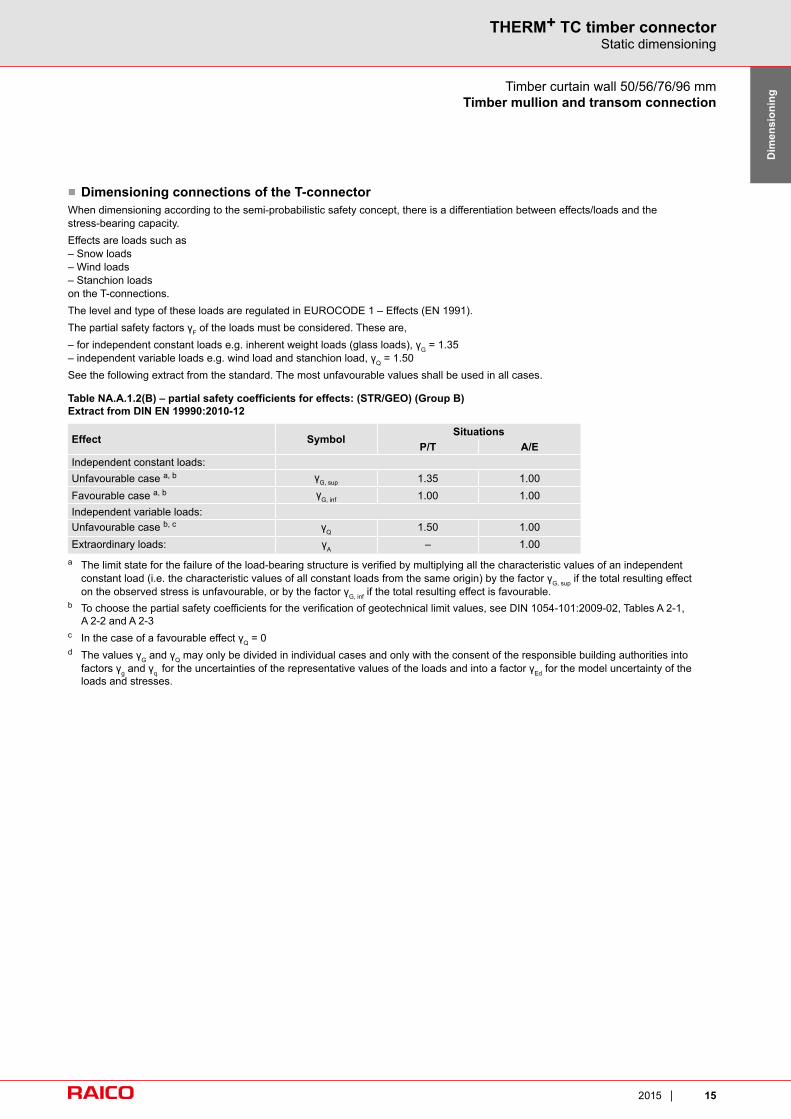
■ Dimensioning connections of the T-connectorWhen dimensioning according to the semi-probabilistic safety concept, there is a differentiation between effects/loads and the stress-bearing capacity.Effects are loads such as– Snow loads– Wind loads– Stanchion loadson the T-connections.The level and type of these loads are regulated in EUROCODE 1 – Effects (EN 1991).The partial safety factors γF of the loads must be considered. These are,– for independent constant loads e.g. inherent weight loads (glass loads), γG = 1.35– independent variable loads e.g. wind load and stanchion load, γQ = 1.50See the following extract from the standard. The most unfavourable values shall be used in all cases.
Table NA.A.1.2(B) – partial safety coefficients for effects: (STR/GEO) (Group B)Extract from DIN EN 19990:2010-12
Effect SymbolSituations
P/T A/EIndependent constant loads:Unfavourable case a, b γG, sup 1.35 1.00Favourable case a, b γG, inf 1.00 1.00Independent variable loads:Unfavourable case b, c γQ 1.50 1.00Extraordinary loads: γA – 1.00
a The limit state for the failure of the load-bearing structure is verified by multiplying all the characteristic values of an independent constant load (i.e. the characteristic values of all constant loads from the same origin) by the factor γG, sup if the total resulting effect on the observed stress is unfavourable, or by the factor γG, inf if the total resulting effect is favourable.
b To choose the partial safety coefficients for the verification of geotechnical limit values, see DIN 1054-101:2009-02, Tables A 2-1, A 2-2 and A 2-3
c In the case of a favourable effect γQ = 0d The values γG and γQ may only be divided in individual cases and only with the consent of the responsible building authorities into
factors γg and γq for the uncertainties of the representative values of the loads and into a factor γEd for the model uncertainty of the loads and stresses.

16 2015
THERM+ TC timber connectorStatic dimensioning
Timber curtain wall 50/56/76/96 mmTimber mullion and transom connection
The probability that all simultaneously occurring effects are at their maximum in one stress direction is extremely slim.In this case, so-called combination rules are applied, in which a variable load is taken into account with its maximum value and all other variable loads are reduced by so-called combination factors.The relevant load case combination is the one with the higher value which is used in mullion and transom façades, e.g. in the case of wind load (wind pressure, wind suction) and stanchion load.The combination factors can be taken from EUROCODE 0. An extract is given below:
Table NA.A.1.1 – Numerical values for combination coefficients in civil engineeringExtract from DIN EN 1990:NA2010-12 – Germany
Effect Ψ0 Ψ1 Ψ2
Payloads in civil engineering (categories see EN 1991-1-1) a
– Category A: Living rooms and staff rooms 0.7 0.5 0.3– Category B: Offi ces 0.7 0.5 0.3– Category C: Conference rooms 0.7 0.7 0.6– Category D: Sales rooms 0.7 0.7 0.6– Category E: Storage rooms 1 0.9 0.8– Category F: Thoroughfares, vehicle load ≤ 30 kN 0.7 0.7 0.6– Category G: Thoroughfares, 30 kN ≤ vehicle load ≤ 160 kN 0.7 0.5 0.3– Category H: Roofs 0 0 0Snow and ice loads, see DIN EN 1991-1-3– Locations up to sea level + 1000 m 0.5 0.2 0Locations above sea level + 1000 m 0.7 0.5 0.2Wind loads, see DIN EN 1991-1-4 0.6 0.2 0Temperature effects (not fi re), see DIN EN 1991-1-5 0.5 0.5 0Construction site settlement, see DIN EN 1997 1 1 1Other effects: b, c 0.8 0.7 0.5
a Reduction coefficients for payloads in multi-storey buildings see DIN EN 1991-1-1.b Fluid pressure is generally treated as a variable load for which the Ψ-coefficients are defined site-specifically. Fluid pressure whose
value is limited by geometrical constraints may be treated as a constant load wherein all Ψ-coefficients should be set to 1.0.c ΨΨ coefficients for machine loads should be defined with respect to the operation.

172015
THERM+ TC timber connectorStatic dimensioning
Dim
ensi
onin
g
■ The stress-bearing capacity/resistance of the T-connectionThe stress-bearing capacity/resistance of the T-connection is regulated in ETA-13/0765.The characteristic strength of the connection at a gross density (gross density of mullions and transoms must be lower) of ρL = 350 kg/m³ can be taken from the following table.
Timber curtain wall 50/56/76/96 mmTimber mullion and transom connection
Table C.1 – Effective quantity nj, nef, 1, nef, 45 and characteristic values F1, RK, F2, RK, F3, RK, F45, RKfor a characteristic gross density of 350 kg/m³
RAICO T-connector nef, 1 F1, RK [kN] nJ
F2, RK [kN]Wind
pressure
F3, RK [kN]Wind
suctionnef, 45 F45, RK [kN] F45, in, RK [kN]
SOLO 60 1.60 3.1 2 3.4 3.4 0.42 1.7 1.0SOLO 80 2.41 4.7 3 5.1 5.1 0.60 2.0 1.0SOLO 100 2.97 5.8 3 5.1 5.1 0.82 2.4 1.0SOLO 120 2.63 5.2 4 6.8 5.8 0.99 2.7 1.0SOLO 160 2.36 4.6 4 6.8 5.8 1.30 3.2 1.0SOLO 200 3.85 7.5 5 7.0 5.8 1.57 3.7 1.0SOLO 240 3.30 6.5 5 7.0 5.8 1.80 4.0 1.0KOMBI 60 1.60 3.1 2 3.4 3.4 0.42 3.7 3.0KOMBI 80 2.41 4.7 3 5.1 5.1 0.60 4.0 3.0KOMBI 100 2.97 5.8 3 5.1 5.1 0.82 5.4 4.0KOMBI 120 2.63 5.2 4 6.8 5.8 0.99 5.7 4.0KOMBI 160 2.36 4.6 4 6.8 5.8 1.30 6.2 4.0KOMBI 200 3.85 7.5 5 7.0 5.8 1.57 6.7 4.0KOMBI 240 3.30 6.5 5 7.0 5.8 1.80 7.0 4.0
At higher gross densities the characteristic strengths are calculated according to the following equations. The forces F1, F2 and F3 always act in the centre of the connector. The force F45 has an eccentricity which corresponds to a maximum infill thickness of 65 mm (based on a symmetrical glass construction; the infill thickness should be reduced for asymmetrical glass constructions). The maximum gross density may not exceed 500 kg/m³. The minimum gross density may not be less than 350 kg/m³.
F45, RK – characteristic value for inherent weight stressF45, RK = 1693 x nef45 x (ρK/350)0.5 + F45,in,RK [N]
F1, RK – characteristics value for tensile stress on the transomF1, RK = nef1 x 1958 x (ρK/350)0.8 [N]
F2, RK – characteristic value in the wind pressure direction
F2, RK = min.
F3, RK – the characteristic value in the wind suction direction
F3, RK = min.
nef, 1 = effective no. of screws for stress direction F1 nef, 45 = effective no. of screws for stress direction F45
nj = no. of screws in the transomPK = gross density in the mullion/transom in kg/m³. The lower value should be used for the dimensioning.F45,in,RK = additional load-bearing capacity in the loading directionThese characteristic values apply only for connectors in pairs for load directions F1, F2, F3 and F45The specified values apply per connection.
s nj x 1693 x (ρK/350)0.5 [N] 7000 N
s nj x 1693 x (ρK/350)0.5 [N] 5800 N

18 2015
THERM+ TC timber connectorStatic dimensioning
Timber curtain wall 50/56/76/96 mmTimber mullion and transom connection
The following should be considered when determining the stress-bearing capacity/resistance of the connection:– Partial safety value for individual materials in timber constructions γM = 1.30 (Germany – national requirements must be taken into account)
Modification coefficient kmod according to EUROCODE 5
Table NA.2 – Partial safety coefficients γM for strength- and stiffness properties in constant and temporary dimensioning situationsExtract from DIN EN 1995-1-1/NA:2010-12 – Germany
Building material γM
Solid wood, chipboards, hard fi breboards, medium hard fi bre-boards, MDF fi breboards, soft fi breboards, laminated veneer lumber, plywood, OSB, laminated timber
1.3
Steel in connections– for bending-stressed dowel-type fasteners 1.3– for tension or shear-stressed parts in verifi cation of resist-
ance to yield stress in the net cross section 1.3
– Board proof of load-bearing capacity for nail boards 1.25
Load effect duration class
Order of magnitude of the accumulated duration of the characteristic load effect
medium 1 week – 6 monthsshort shorter than a weekvery short shorter than a minute
Note: Examples for assignment to duration of load effect classes can be found in Table 2.2. Climate-related load effects (snow, wind) vary in magnitude in different countries so the national appendix is used for assignment to load effect duration classes.

192015
THERM+ TC timber connectorStatic dimensioning
Dim
ensi
onin
g
Table NA.1 – Breakdown of loads according to DIN 1055-1, DIN 1055-3, DIN 1055-4, DIN 1055-5, DIN 1055-9, DIN 1055-10 and DIN 1055-100 in load effect duration classes (KLED)Extract from DIN EN 1995-1-1-2010-12 – Germany
Effect KLEDSpecifi c weights and surface loads according to DIN 1055-1 constant
Perpendicular payloads DIN 1055-3A Top ground, living- and staff rooms mediumB Offi ce surfaces, working surfaces, corridors mediumC Rooms, conference rooms and surfaces which may be used
for gatherings (with exception of categories defi ned under A, B, D and E)
short
D Sales rooms mediumE Factories and workshops, sheds, storage surfaces and
accesses, surfaces with considerable footfall long
F Roads and parking surfaces for lightweight vehicles (total load ≤ kN), access ramps to these surfaces
mediumshort
G Surfaces for operation with counterweight stackers mediumH Non weight-bearing roofs, except for typical maintenance
or repair short
K Helicopter normal loads shortT Staircases and stair landings shortZ Accesses, balconies and similar short
Horizontal payloads according to DIN 1055-3Horizontal payloads from persons on balustrades, landings and the constructions used as barriers short
Horizontal payloads for achieving adequate longitudinal and transverse rigidity
a
Horizontal loads for helicopter landing pads on fl at roofs– for horizontal payloads– for rollover protection
shortvery short
Wind loads according to DIN 1055-4 short/very short b
Snow load and ice load according to DIN 1055-5Height of construction site above sea level < 1000 m shortHeight of construction site above sea level > 1000 m medium
Impact loads according to DIN 1055-9 very shortHorizontal loads from crane and machine operation according to DIN 1055-10 short
a Corresponding to the associated loads.b For wind, kmod the average of short and very short can be used.
Timber curtain wall 50/56/76/96 mmTimber mullion and transom connection

20 2015
THERM+ TC timber connectorStatic dimensioning
Table NA.4 – Calculated values for modification coefficients kmod for timber, timber- and plaster materialsExtract from DIN EN 1995-1-1/NA:2010-12 – Germany
Load effect duration class
Building material Standard Service class constant effect long effect medium
effect short effect very short effect
Laminated beams, cross-laminated timber, solid timber boards
1 0.60 0.70 0.80 0.90 1.10
2 0.60 0.70 0.80 0.90 1.10
Gypsum boards (types GKB, GKF, GKBI and GKFI), gypsum fi bre boards
DIN 18180, DIN EN 15283-2
1 0.20 0.40 0.60 0.80 1.10
2 0.15 0.30 0.45 0.60 0.80
Cement bonded chipboards
1 0.30 0.45 0.65 0.85 1.102 0.20 0.30 0.45 0.60 0.80
Please note that the table is taken from the national appendix (D) of the Eurocode. If used in other countries the correspondingly applicable values must be used.Example:Glass loads = inherent weight load = constant effect, kmod = 0.6Wind loads = average value of short and very short effect kmod = 1.0Impact loads = very short effect, kmod = 1.10
To dimension the connector, the effects are compared with the load-bearing capacity of the connector.In this case the following applies:
FED / FRD ≤ 1 wherein
FED = design value of force resulting from the stress
FRD = design value of the load-bearing capacity of the fastener resulting from the admissible values, taking into account coefficients.
In the event of load case combinations these are superimposed according to the calculation formula (B1.5), see ETA-13/0765 as follows:
(F1,ED / F1,RD)² + (F23,ED / F23,RD)² + (F45,ED / F45,RD)² ≤ 1
Timber curtain wall 50/56/76/96 mmTimber mullion and transom connection

Feldbreite
oben
Feldhöhe
unten
Feldhöhe
212015
THERM+ TC timber connectorStatic dimensioning
Dim
ensi
onin
g
Stress surface Aw■ Example of calculation on the basis of the façade element shownField width = 2.3 mField height upper = 2.6 mField height lower = 0.9 mTotal glass thickness = 16 mmStanchion load = 1.0 kN/m (cat B)Wind load suction + pressure = 0.5 KN/m²
The inherent weight of the transom is not taken into account in this calculation.Gross density of laminated timber = 350 kg/m³Use: Hotel
EffectsInherent weight load = glass load on the transomGlass weight = 2.3 x 2.6 x 16 x 2.5 ≈ 212 kg = 2.12 KNPartial safety factor of the effectϒG = 1.35 for independent constant loadsF45,ED = 2.12 KN x 1.35 = 2.86 KN
Load surfaces for wind load/stanchion load:The wind suction load case is relevant in this case because it acts in the same direction as the stanchion load. In the case of type 1: Aw = = = 1.32 m2
In the case of type 2: Aw = –
= – = 0.83 m2
Total stress surface = 1.32 m² + 0.83 m² = 2.15 m²
Calculating of wind load on the transom:Total wind load = 2.15 m² x 0.5 kN/m² = 1.08 KN
Partial safety factor of the effect γQ = 1.50
FW,ED = 1.08 x 1.50 = 1.62 KN
Stanchion load FH = transom length x stanchion load
= 2.3 m x 1.0 KN/m = 2.3 KN
FH,ED = 2.30 x 1.50 = 3.45 KN
Superimposition of the wind load and stanchion load:
ψO = 0.6 for wind loads / 0.8 for other loads (Germany)
LFK1: F3,ED = FW,ED + FH,ED x 0.8
= 1.62 + 3.45 x 0.8 = 4.38 KN
LFK2: F3,ED = FH,ED + FW,ED x 0.6
= 3.45 + 1.62 x 0.6 = 4.42 KN
Load case combination 2 is relevant.
Field width x field width4
Timber curtain wall 50/56/76/96 mmTimber mullion and transom connection
2.3 m x 2.3 m4
Field width x field height lower2
Field height lower x field height lower4
2.3 m x 0.9 m2
0.9 m x 0.9 m4
field width
field
hei
ght
field
hei
ght
uppe
rlo
wer
AW type 1: Triangular loadField height > field width
AW type 2: Trapezoidal loadField height < field width

22 2015
THERM+ TC timber connectorStatic dimensioning
Resistance of the connector:
SOLO 143 connector is used.
On the basis of the gross density, the values from Table C1 – ETA-13/0765 can be used.
These are:
F1,RK = 4.6 KNF3,RK (wind suction) = 5.8 KNF45,RK = 3.2 KN
Please note that these values apply per connection and in the following calculation for a transom they are multiplied by a factor of 2.
Resistance of the T-connectors in direction F45 – glass load
Kmod for BSH service class 2 = 0.6
Safety factor γM for BSH = 1.30
F45,RD+ = F45,RK x (2 x 0.6 / 1.30) = 2.95 KN
Resistance of the T-connection in direction F3 – wind suction
Kmod for BSH service class 1 + 2 = 1.0 for wind loads = 1.10 for stanchion loads
Because of the different Kmod the lower value of 1.0 is used for the calculation.
Safety factor γM for BSH = 1.30
F3,RD = = 8.92 KN The load F1 is not taken into account.
Proof for F45
= = 0,97 Proof for F3
= = 0,5
Proof for combined load:
(F1,ED / F1,RD)² + (F3,ED / F3,RD)² + (F45,ED / F45,RD)² < 1
(0 / 0)² + 0.5² + 0.97² = 0 + 0.24 + 0.94 = 1.19
F3,RK x 2 x 1.01.3
F45,ED F45,RD
F3,ED F3,RD
2.86 2.95
4.42 8.92
Timber curtain wall 50/56/76/96 mmTimber mullion and transom connection

232015
THERM+ TC timber connectorStatic dimensioning
Dim
ensi
onin
g
■ Result The connector cannot sustain the loads imposed.A lower connector or a KOMBI type connector must be used.In the case of the KOMBI 143, while maintaining the values, the following load-bearing capacities are obtained on the basis of the following values:
F1,RK = 4.6 KNF3,RK (wind suction) = 5.8 KNF45,RK = 6.2 KN
F45,RD = = 5.72 KN F3,RD = = 8.92 KN Verification for combined loads with the KOMBI type connector:
(F1,ED / F1,RD)² + (F3,ED / F3,RD)² + (F45,ED / F45,RD)² =
(0 / 0)² + (4.42 / 8.92)² + (2.86 / 5.72)² =
0 + 0.5² + 0.52 = 0.5
This verification is satisfied; the load-bearing capacity of the connector is adequate.
The following table provides orientation for the design width of the SOLO and KOMBI T-connectors taking into account the following factors:
Gross density timber = 350 kg/m³Kmod = 0.6 for load type F45Kmod = 1.0 for load type F2.3Kmod = 0.6 for load type F1
Partial safety factor of material γM= 1.30Partial safety factor of constant load γG = 1.35Partial safety factor of variable load γQ = 1.50
6.2 x 2 x 0.61.3
5.8 x 2 x 1.01.3
Design value for maximum glass load in direction F45 per transom (load case combinations shall be superimposed)
SOLO KOMBITC60 116 kg 253 kgTC80 138 kg 274 kgTC100 162 kg 367 kgTC120 182 kg 388 kgTC160 218 kg 423 kgTC200 250 kg 455 kgTC240 276 kg 481 kg
Design value for maximum wind pressure-/suction load in direction F2,3 per transom(load case combinations shall be superimposed)
F2 – wind pressure F3 – wind suction
TC SOLO/KOMBI 60 3.47 KN 3.47 KNTC SOLO/KOMBI 80 5.21 KN 5.21 KNTC SOLO/KOMBI 100 5.21 KN 5.21 KNTC SOLO/KOMBI 120 6.95 KN 5.95 KNTC SOLO/KOMBI 160 6.95 KN 5.95 KNTC SOLO/KOMBI 200 7.18 KN 5.95 KNTC SOLO/KOMBI 240 7.18 KN 5.95 KN
Timber curtain wall 50/56/76/96 mmTimber mullion and transom connection

24 2015