Theory of XRDwebsite.ppt - Prolab Systems Jeddah... · Theory of XRD The principles behind X-ray...
75
Theory of XRD The principles behind X-ray diffraction 16 April 2012 Ing. Bas ter Mull Area Business Manager
Transcript of Theory of XRDwebsite.ppt - Prolab Systems Jeddah... · Theory of XRD The principles behind X-ray...

Theory of XRD
The principles behind X-ray diffraction 16 April 2012Ing. Bas ter MullArea Business Manager

Overview
• Introduction• XRD versus XRF• What is diffraction ?• XRD analysis • Focusing optics• Detectors
4/14/2012 2Workshop XRF & XRD, Abu Dhabi

States of matter
SOLID LIQUID GAS
Note: XRD can only measure the solid ! ! !
4/14/2012 3Workshop XRF & XRD, Abu Dhabi

Matter in solid stateCrystalline Amorphous
Single crystal Polycrystalline
4/14/2012 4Workshop XRF & XRD, Abu Dhabi
Overview
• Introduction• XRD versus XRF• What is diffraction ?• XRD analysis • Focusing optics• Detectors• Products
4/14/2012 5Workshop XRF & XRD, Abu Dhabi

The difference of XRD to XRF
• Let us have a look to the analysis of a Limestone– …from an XRF point of view
– … and from an XRD point of view
4/14/2012 6Workshop XRF & XRD, Abu Dhabi

The difference of XRD to XRF
The real questions on these results from XRD perspective are:
Is all Ca really represented with Calcite (CaCO3) ?Is the calculated oxide for Si the right number?Is SiO2 Quartz or is it Cristoballite or is it perhaps amorphous SiliconOxide? Is the Magnesite present? (MgCO3)Is this MgCO3 calculation right?
Analyte Compound Concentrationformula (%)
Mg MgCO3 2.91Al Al2O3 0.39Si S iO2 1.16P P2O5 0.01S SO3 0.01K K2O 0.06Ca CaCO3 95.16Ti TiO2 0.02Mn MnO 0.01Fe FeCO3 0.20Sr SrO 0.06Zr ZrO2 0.01Cl Cl 0.00
Results obtained by XRF analysis
4/14/2012 7Workshop XRF & XRD, Abu Dhabi

The difference of XRD to XRF
• The results on the limestone obtained by XRD - Rietveld analysis
– CaCO3 Calcite: 86.3 %
– CaMg(CO3)2 Dolomite: 12.6 %
– SiO2 Quartz: 1.1 %
– No Magnesite (MgCO3)!
Analyte Compound Concentrationformula (%)
Mg MgCO3 2.91Al Al2O3 0.39Si S iO2 1.16P P2O5 0.01S SO3 0.01K K2O 0.06Ca CaCO3 95.16Ti TiO2 0.02Mn MnO 0.01Fe FeCO3 0.20Sr SrO 0.06Zr ZrO2 0.01Cl Cl 0.00
Results obtained by XRF analysis
4/14/2012 8Workshop XRF & XRD, Abu Dhabi

Overview
• Introduction• XRD versus XRF• What is diffraction ?• XRD analysis • Focusing optics• Detectors
4/14/2012 9Workshop XRF & XRD, Abu Dhabi

XRD
Scattering is the interaction of waves with matter
– Electromagnetic radiation is scattered at atoms, molecules and ions
– Scattering of visible light in gases (Raleigh-scattering in the atmosphere)
• …. and in crystals ?
4/14/2012 10Workshop XRF & XRD, Abu Dhabi

XRD
• A single particle scatters in all directions
• In crystals an incident single wavelength is scattered into distinct directions. This is caused by interference of the scattered beams.
• The directions and intensity of the beams depend on the distances and on the type of the building blocks (atoms, ions, molecules) the crystal lattice is made of; and on the wavelength.
• An ideal powder sample represents all possible orientations of a crystal in space.
4/14/2012 11Workshop XRF & XRD, Abu Dhabi

XRDX-ray diffraction is used for:
• Fingerprinting - (qualitative) characterization of crystalline solids
• Quantitative determination of phases in mixtures
• --------------------------------------------------------------• High resolution diffraction of epitaxial thin films (semiconductors...)
• Reflectometry (Δ density, thickness, roughness)
• Determination of the structure of (single) crystals
• Texture, orientation distribution function
• Stress, determination of the lattice strain
• High-throughput screening, crystallization experiments (solvates, solvents)
• -------------------------------------------------------------
X-ray diffraction is the most important characterization tool used in mineralogy, solid state chemistry and material science !!!
4/14/2012 12Workshop XRF & XRD, Abu Dhabi

X-rays: electromagnetic radiation with a wavelength from 0.1 Å to 100 Å (0.01 nm to about 10 nm).
What are X-rays?
4/14/2012 13Workshop XRF & XRD, Abu Dhabi

Generation of X-rays
• Electrons are emitted by a hot filament
• High voltage accelerates electrons
• Electrons bombard anode material at high speed
• Kinetic energy of electrons largely transferred into heat and X-ray radiation
Current (mA)
Voltage (kV)
4/14/2012 14Workshop XRF & XRD, Abu Dhabi

Generation of X-rays
Continuous radiation: caused by deceleration of electrons when passing the positively charged nuclei in the anode or when colliding with electrons of the anode atoms.
KL
M
Radiation (Bremsstrahlung)
Decelerated electron
4/14/2012 15Workshop XRF & XRD, Abu Dhabi

KL
M
Knocked-out electron
Decelerated electron
Generation of X-rays
Characteristic radiation: When an atom is bombarded with sufficiently high energy electrons (E > Ec ) electrons can be knocked out from their shell.
4/14/2012 16Workshop XRF & XRD, Abu Dhabi

Characteristic radiation: An electron from a higher shell takes the place of the knocked-out electron. The energy difference between both shells is released in the form of X-ray radiation of a specific wavelength.
KL
M
Characteristic radiation
KαKβ
Generation of X-rays
4/14/2012 17Workshop XRF & XRD, Abu Dhabi

Generation of X-rays
L-shell
III
III
Kα2 Kα1
K-shell
Generation of X-rays
Kα1 and Kα2 radiation:
Kα radiation comprises two wavelengths: Kα1 and Kα2.
The wavelengths correspond to the transitions from the L-shell to the K-shell. The L-shell has three energy levels from which level I is empty.
4/14/2012 18Workshop XRF & XRD, Abu Dhabi

NaCl - Sodium Chloride
A Simple Crystal Structure
4/14/2012 19Workshop XRF & XRD, Abu Dhabi

A crystal is constructed by the ‘infinite’ repetition in space of identical ‘building blocks’.
Grid system
Building block
Crystal+
b
a
The Crystalline State
4/14/2012 20Workshop XRF & XRD, Abu Dhabi

Building block describes arrangement of groups of atoms
Grid system describes how building block repeat in space
The lattice parameters describe the ‘infinite repetition’ unit. A volume element whose edges are successive grid lines.
The Crystalline State
4/14/2012 21Workshop XRF & XRD, Abu Dhabi

The (111) planes
Lattice Planes
4/14/2012 22Workshop XRF & XRD, Abu Dhabi

d100
c
b
ad200
Lattice Planes
(100) (200) (110)
(110) (111) (102)
4/14/2012 23Workshop XRF & XRD, Abu Dhabi

X-ray diffraction
λ 2λ 3λ
First order Second order Third order
d
θ θC
D
B
B’
A
A’
λλ
d
A C
B
B'
B"
C'
C"
A'
A"
θ
Bragg’s law:
nλ=2dsinθConstructive interference is
detected when the path-length difference is equal to an
integer number of wavelengths
4/14/2012 24Workshop XRF & XRD, Abu Dhabi

Technique 2d sin θ
XRF Unknown Fixed Variable
XRD Fixed Unknown Variable
n λ
XRD versus XRF
4/14/2012 25Workshop XRF & XRD, Abu Dhabi

X-ray diffraction experiment
2d
Incident beam
Lattice plane 1
4/14/2012 26Workshop XRF & XRD, Abu Dhabi

X-ray diffraction experiment
2d
Incident beam
Lattice plane 2
4/14/2012 27Workshop XRF & XRD, Abu Dhabi

X-ray diffraction experiment
2d
Incident beam
Lattice plane 3
4/14/2012 28Workshop XRF & XRD, Abu Dhabi

This is later the result: A diffraction pattern ! ! !
4/14/2012 29Workshop XRF & XRD, Abu Dhabi

Structure
• The d-spacings of lattice planes depend on the size of the unit cell and determine the position of the peaks.
• The intensity of each peak is caused by the crystallographic structure, i.e. the position of the atoms within the unit cell and their thermal vibration.
• The line width and shape of the peaks may be derived from conditions of measuring and properties - like particle size - of the sample material.
4/14/2012 30Workshop XRF & XRD, Abu Dhabi

XRD is a 3D phenomina
4/14/2012 31Workshop XRF & XRD, Abu Dhabi

3D picture of powdser and poly crystalline samples
4/14/2012 32Workshop XRF & XRD, Abu Dhabi

3D picture of powdser and poly crystalline samples
4/14/2012 33Workshop XRF & XRD, Abu Dhabi

Overview
• Introduction• XRD versus XRF• What is diffraction ?• XRD analysis • Focusing optics• Detectors• Products
4/14/2012 34Workshop XRF & XRD, Abu Dhabi
XRD… How does it work and what information can it deliver
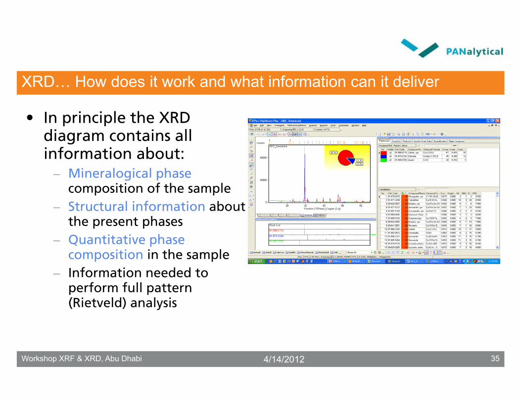
• In principle the XRD diagram contains all information about:
– Mineralogical phasecomposition of the sample
– Structural information about the present phases
– Quantitative phase composition in the sample
– Information needed to perform full pattern (Rietveld) analysis
4/14/2012 35Workshop XRF & XRD, Abu Dhabi

XRD… How does it work and what information can it deliver
What sort of information ispresent in this picture?
4/14/2012 36Workshop XRF & XRD, Abu Dhabi
XRD… How does it work and what information can it deliver
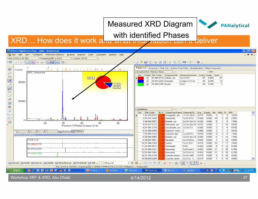
Measured XRD Diagramwith identified Phases
4/14/2012 37Workshop XRF & XRD, Abu Dhabi

XRD… How does it work and what information can it deliver
Identified Phases
4/14/2012 38Workshop XRF & XRD, Abu Dhabi

XRD… How does it work and what information can it deliver
List of possible candidatesderived from ICDD database
4/14/2012 39Workshop XRF & XRD, Abu Dhabi

XRD… How does it work and what information can it deliver
Mineralogical (database) and semi – quantitative info
about the identified Phases
4/14/2012 40Workshop XRF & XRD, Abu Dhabi

XRD
- RIR- Calibration- Rietveld
Structure and Microstructure Analysis
Qualitative Quantitative
Phase Analysis
X-Ray Powder DiffractionApplications
4/14/2012 41Workshop XRF & XRD, Abu Dhabi

Overview
• Introduction• XRD versus XRF• What is diffraction ?• XRD analysis • Focusing optics• Detectors
4/14/2012 42Workshop XRF & XRD, Abu Dhabi

X-ray tube
Soller slit Soller slit
Anti-scatter slit
Receiving slit
Monochr.
Divergence slit
Sample stage
Mask
Detector
Goniometer
Classical Powder Diffractometer
4/14/2012 43Workshop XRF & XRD, Abu Dhabi

Element Symbol Kαλ [nm] Application Chromium Cr 0.2291 large unit cells (clays, organic
materials, zeolites), steel (residual stress)
Iron Fe 0.1937 matrix effects of Fe and Cr Cobalt Co 0.1791 ferro materials Copper Cu 0.1542 standard tube Molybdenum Mo 0.0710 single crystal, small unit cells (metals) Silver Ag 0.0561 high absorbing materials Tungsten W 0.0211 Laue camera (continuum needed)
X-ray Operation Conditions
Anode material = choice of wavelength
4/14/2012 44Workshop XRF & XRD, Abu Dhabi

line focus
pointfocus
Point•micro-diffraction•texture•psi-stress
Line•general•phase analysis•omega-stress
X-ray Operation Conditions
Focus orientation: line focus and point focus
4/14/2012 45Workshop XRF & XRD, Abu Dhabi

divergence slit anti-scatter slit
Divergence Slit & Anti-scatter Slit
Divergence slit & anti-scatter slit: determining illuminated and observed length
4/14/2012 46Workshop XRF & XRD, Abu Dhabi

Influence of divergence slit
opening
Divergence Slit & Anti-Scatter Slit
4/14/2012 47Workshop XRF & XRD, Abu Dhabi

tube focus receiving slit
Tube Focus and Receiving Slit
Tube focus and receiving slit: determining instrument resolution
4/14/2012 48Workshop XRF & XRD, Abu Dhabi

Receiving slit settings (6º take-off angle)
Tube Focus and Receiving Slit
4/14/2012 49Workshop XRF & XRD, Abu Dhabi

Soller slit Soller slit
Soller Slits
Soller slits: limiting axial divergence
4/14/2012 50Workshop XRF & XRD, Abu Dhabi

Soller Slits
• Soller slits consist of large numbers of parallel plates in the plane of diffraction.
• Soller slits limit the spread of the incident and diffracted X-ray beam out of the plane of diffraction: 0.02, 0.04 and 0.08 rad.
– large effect on intensities
– moderate effect on resolution (low/high 2θ)
• It is good practice to place similar Soller slits in the incident and diffracted beam.
4/14/2012 51Workshop XRF & XRD, Abu Dhabi

Effect of Soller Slits
Soller Slits
4/14/2012 52Workshop XRF & XRD, Abu Dhabi

β-filter & Monochromator
diffracted beam
monochromator
Possible places β-filter
β-filter & Monochromator
β-filter or monochromator: removing
unwanted radiation
4/14/2012 53Workshop XRF & XRD, Abu Dhabi

β-filter & Monochromator
• The β-filter and the diffracted beam monochromator remove unwanted wavelengths like the Kβ-line and continuous radiation.
• The β-filter selectively absorbs radiation.
• Monochromators select radiation by means of diffraction.
4/14/2012 54Workshop XRF & XRD, Abu Dhabi

Sup
pre
ssio
n
Wavelength
Cu
Kα
W L
αC
u K
β
Ni filter
β-filter & Monochromator
Use filter material with absorption edgein between Kα and Kβline.
For example:Cu-radiation
Ni filter• Intensity Cu Kα : 50 %• Intensity Cu Kβ : 1%
4/14/2012 55Workshop XRF & XRD, Abu Dhabi

Element Symbol
β-filter
Thickness [μm]
Kβ reductio
n
Kα reductio
n Chromium Cr V 13 98 45 Cobalt Co Fe 16 99 51 Copper Cu Ni 20 99 58 Molybdenum Mo Zr 75 97 54
β-filter & Monochromator
Anode materials and corresponding β-filters
4/14/2012 56Workshop XRF & XRD, Abu Dhabi

receiving slit
Curved graphite diffractedbeam monochromator
detector entrance slit
λ > λCu
λ < λCu
β-filter & Monochromator
Only X-ray waves with correct wavelength pass the entrance slit of the detector.
Others do not focus in the entrance slit of the detector.
4/14/2012 57Workshop XRF & XRD, Abu Dhabi

Diffracted Beam Monochromator
Anti scatter slit
Detector
Curved crystalmonochromator(Graphite)
Receiving slit
Polycrystalline sample
Soller slits
X-ray tube(line focus)
Divergence slit
Soller slits
Beam mask
4/14/2012 58Workshop XRF & XRD, Abu Dhabi

Overview
• Introduction• XRD versus XRF• What is diffraction ?• XRD analysis • Focusing optics• Detectors
4/14/2012 59Workshop XRF & XRD, Abu Dhabi

Detection of X-rays
• Gas filled proportional detectors
• Linear Detectors– X’Celerator
– PIXcel
4/14/2012 60Workshop XRF & XRD, Abu Dhabi
Detection of X-rays
• Gas Filled Proportional Detectors– For wavelengths longer than Cu Kα or lower energy
than 8 keV
– Filled with a mixture of gasses: argon-methane, xenon-methane or neon-methane
– X-rays ionize the gas in the detector
4/14/2012 61Workshop XRF & XRD, Abu Dhabi

X-rays ionize the gas, the ions are drawn to the wire by the high tension. At the wire they cause a dip in the high voltage which is counted as a pulse.
Detection of X-rays
Gas Filled Detector +HT
C
A
X-rays in
Time
V
4/14/2012 62Workshop XRF & XRD, Abu Dhabi
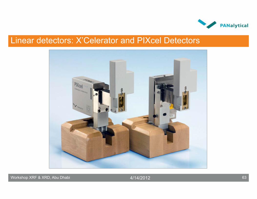
Linear detectors: X’Celerator and PIXcel Detectors
4/14/2012 63Workshop XRF & XRD, Abu Dhabi

X’Celerator and PIXcel Detector
• Fast collection of diffraction data through many individual detectors in a row
• No compromise in resolution for powders and other polycrystalline materials
• Easy to use - no re-calibration, gas flow or cooling water
4/14/2012 64Workshop XRF & XRD, Abu Dhabi

Point detectors in Bragg – Brentano mode
Receiving slit + detector
Polycrystalline sample
Line focus
Divergence slit
Scan directionScan direction
Classical geometry (Bragg-Brentano)
4/14/2012 65Workshop XRF & XRD, Abu Dhabi

Polycrystalline sample
active length
Scanning Mode
Each strip acts as an individual detector
4/14/2012 66Workshop XRF & XRD, Abu Dhabi

What is RTMS Technology ?
Polycrystalline sample
X’Celerator
Line focus
Divergence slit
Scan directionScan direction
4/14/2012 67Workshop XRF & XRD, Abu Dhabi

What is RTMS Technology ?
Polycrystalline sample
X’Celerator
Line focus
Divergence slit
Scan directionScan direction
4/14/2012 68Workshop XRF & XRD, Abu Dhabi

What is RTMS Technology ?
Polycrystalline sample
X’Celerator
Line focus
Divergence slit
Scan directionScan direction
4/14/2012 69Workshop XRF & XRD, Abu Dhabi

PIXcel
• the PIXcel detector: the One
4/14/2012 70Workshop XRF & XRD, Abu Dhabi

What is the PIXcel Detector?
• The PIXcel is a solid state detector that comprises more than 65,000 pixels, each 55 x 55 microns in size.
• Each pixel has its own circuitry, giving rapid readout time and high dynamic range: more than 13 million counts per second per pixel row.
4/14/2012 71Workshop XRF & XRD, Abu Dhabi

PIXcel: Count Rate Linearity per Pixel Row
PIXcel count rate linearity
0.0E+00
1.0E+07
2.0E+07
3.0E+07
0.0E+00 1.0E+07 2.0E+07 3.0E+07
Incident intensity (cps)
Mea
sure
d in
tens
ity (c
ps)
PIXcel detectorIdeal line
4/14/2012 72Workshop XRF & XRD, Abu Dhabi

PIXcel Detector Versus X’Celerator Detector
• For scanning applications only, a PIXcel collects similar data as an X’Celerator
• It is up to 150 % faster
• It has the smallest channel width
• Possibilities for static measurements
• Possibilities for high dynamic range point detector measurements
• Maintenance-free detector (even no cooling fan needed)
4/14/2012 73Workshop XRF & XRD, Abu Dhabi

PIXcel Applications: Static Measurements
• PIXcel offers static measurements– Possible to take snapshots with a time resolution of
only few seconds
• Useful for several applications– Non-ambient measurements (phase transitions)– Also for nano-materials
• Use of special interface that allows to put the detector closer to the sample
4/14/2012 74Workshop XRF & XRD, Abu Dhabi

2D X-ray diffractionIn a 2D 2theta scan the 2Ddetector intercepts a number of diffraction cones resulting in Debye rings at different 2thetapositions
4/14/2012 75Workshop XRF & XRD, Abu Dhabi