
Theory of Linac
13
Accelerator Magnets Theory Page 1 of 13 file://C:\My Documents\Kholid\radiotherapy\linac\Linac Basics-2.htm 6/8/06 I. Accelerator Magnet Theory A. Electricity and Magnetism background. In order to keep the accelerated beam within the confines of a circular accelerator, it is necessary to modify the trajectory of the beam . This is accomplished by electromagnets in most cases. In order to more fully understand how the this is done, a short survey of the concepts of electricity and magnetism as they apply to the various magnet systems will be presented. The following discussion will focus primarily on the magnetic aspects of Maxwell's equations as well as the force equation. In review, the four Maxwell Equations in a vacuum are: and the force equation, In the following discussions, it would be helpful to layout the type of coordinate system that will be used for this chapter, and many other discussions of particle trajectories. The coordinate system is a right-handed cartesian system with the z-axis pointing along the direction of the design orbit path, the x axis pointing radially outward, and the y axis pointing vertically upward as in the diagram below. As a help in understanding the configurations of magnetic fields that an operator may see used in the accelerators, a slight digression will be made here to show how an arbitrary magnetic field can be described in terms of a basic field configurations. In other words, a magnetic field can be described by combining basic field patterns of various amplitudes to describe a complex system. This would be akin to describing an AC square wave as a superposition of various sine and cosine waves. To begin with, consider an arbitrary magnetic field distribution along a fixed line in space. If this magnetic field is described by a function then a Taylor series expansion can be made of this function about the origin, and will have the form below.
-
Upload
wilda-amananti -
Category
Documents
-
view
27 -
download
0
description
BFB
Transcript of Theory of Linac

Accelerator Magnets Theory Page 1 of 13
file://C:\My Documents\Kholid\radiotherapy\linac\Linac Basics-2.htm 6/8/06
I. Accelerator Magnet TheoryA. Electricity and Magnetism background.
In order to keep the accelerated beam within the confines of a circular accelerator, it is necessary to modify the trajectory of the beam . This is accomplished by electromagnets in most cases. In order to more fully understand how the this is done, a short survey of the concepts of electricity and magnetism as they apply to the various magnet systems will be presented. The following discussion will focus primarily on the magnetic aspects of Maxwell's equations as well as the force equation. In review, the four Maxwell Equations in a vacuum are:
and the force equation,
In the following discussions, it would be helpful to layout the type of coordinate system that will be used for this chapter, and many other discussions of particle trajectories. The coordinate system is a right-handed cartesian system with the z-axis pointing along the direction of the design orbit path, the x axis pointing radially outward, and the y axis pointing vertically upward as in the diagram below.
As a help in understanding the configurations of magnetic fields that an operator may see used in the accelerators, a slight digression will be made here to show how an arbitrary magnetic field can be described in terms of a basic field configurations. In other words, a magnetic field can be described by combining basic field patterns of various amplitudes to describe a complex system. This would be akin to describing an AC square wave as a superposition of various sine and cosine waves. To begin with, consider an arbitrary magnetic field distribution along a fixed line in space. If this magnetic field is described by a function then a Taylor series expansion can be made of this function about the origin, and will have the form below.

Accelerator Magnets Theory Page 2 of 13
file://C:\My Documents\Kholid\radiotherapy\linac\Linac Basics-2.htm 6/8/06
Throughout the rest of this chapter, various magnet types will be presented as well as their relationship to the equation form above. B. Bend magnets.The purpose of an accelerator is to accelerate charged particles. In our case the charged particles are either H- ions, protons or antiprotons, depending on the accelerator. The acceleration of the charged particles is accomplished with RF cavities. The design of the Linac, for instance, has been such that it has the necessary number of RF cavities to accelerate beam to 400 MeV with the beam passing through the RF cavities only once. As the energy of the accelerator increases, it becomes impractical to rely on the beam making a single pass through the RF cavities to get the necessary boost. This is because either the number of RF cavities is impractical, or the resulting length of the linear accelerator would be prohibitive, or the electric fields necessary in the RF cavities would be unattainable. For high energy machines, the acceleration process must rely on multiple passes through the accelerating cavities, thereby effectively multiplying the number of RF cavities in the accelerator. In order to accomplish the multiple pass scheme, the beam must travel in a large circle, with the RF cavities located in one arc of the circle. If a region had only a uniform magnetic field, then from the force equation above, a charged particle will follow a circular trajectory while passing through this region.
Initially accelerators called Betatrons would use the above principle with a very large uniform field area, and have the particle trace out a circular path within the field region. Unfortunately, there were limitations to the size of such machines as well as the uniformity of the field. A better system was to have a string of magnets distributed around in a ring, thereby creating a uniform field region confined to an annulus of the required radius.
The ring is made up of electromagnets with a uniform field region. This is produced by having coils of copper piping or bus within the magnets, and using the permeability of the iron of which the magnets are constructed to help shape the field lines. Below is a cross-section of a bend magnet.
The bend magnet produces a vertical magnetic field that in turn produces a radial force on the charged particle causing the particle to follow a radial path. If the current in the coils of the magnet tracks the energy of the charged particle, it is possible to keep the particle
Accelerator Magnets Theory Page 3 of 13
file://C:\My Documents\Kholid\radiotherapy\linac\Linac Basics-2.htm 6/8/06
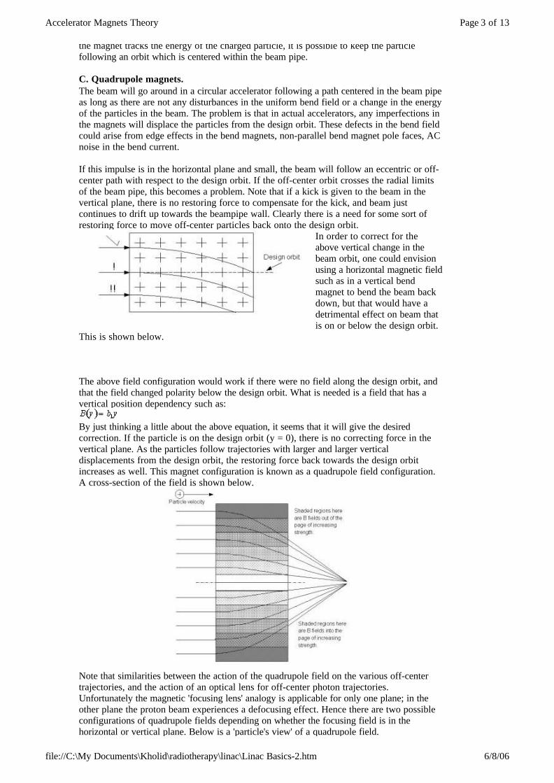
the magnet tracks the energy of the charged particle, it is possible to keep the particle following an orbit which is centered within the beam pipe. C. Quadrupole magnets.The beam will go around in a circular accelerator following a path centered in the beam pipe as long as there are not any disturbances in the uniform bend field or a change in the energy of the particles in the beam. The problem is that in actual accelerators, any imperfections in the magnets will displace the particles from the design orbit. These defects in the bend field could arise from edge effects in the bend magnets, non-parallel bend magnet pole faces, AC noise in the bend current. If this impulse is in the horizontal plane and small, the beam will follow an eccentric or off-center path with respect to the design orbit. If the off-center orbit crosses the radial limits of the beam pipe, this becomes a problem. Note that if a kick is given to the beam in the vertical plane, there is no restoring force to compensate for the kick, and beam just continues to drift up towards the beampipe wall. Clearly there is a need for some sort of restoring force to move off-center particles back onto the design orbit.
In order to correct for the above vertical change in the beam orbit, one could envision using a horizontal magnetic field such as in a vertical bend magnet to bend the beam back down, but that would have a detrimental effect on beam that is on or below the design orbit.
This is shown below. The above field configuration would work if there were no field along the design orbit, and that the field changed polarity below the design orbit. What is needed is a field that has a vertical position dependency such as:
By just thinking a little about the above equation, it seems that it will give the desired correction. If the particle is on the design orbit (y = 0), there is no correcting force in the vertical plane. As the particles follow trajectories with larger and larger vertical displacements from the design orbit, the restoring force back towards the design orbit increases as well. This magnet configuration is known as a quadrupole field configuration. A cross-section of the field is shown below.
Note that similarities between the action of the quadrupole field on the various off-center trajectories, and the action of an optical lens for off-center photon trajectories. Unfortunately the magnetic 'focusing lens' analogy is applicable for only one plane; in the other plane the proton beam experiences a defocusing effect. Hence there are two possible configurations of quadrupole fields depending on whether the focusing field is in the horizontal or vertical plane. Below is a 'particle's view' of a quadrupole field.

Accelerator Magnets Theory Page 4 of 13
file://C:\My Documents\Kholid\radiotherapy\linac\Linac Basics-2.htm 6/8/06
The categorizing of quadrupole fields as either being focusing or defocusing is a common theme in the discussion of accelerators with the horizontal field being the plane used for the definition. In other words, a quadrupole with a horizontal restoring force field is referred to as a focusing quadrupole (an F quad) whereas a quadrupole with a vertical restoring force field is referred to as a defocusing quadrupole (a D quad). 1. Defocusing quads.Looking at the equation given above, there is a focusing or restoring force in the Y axis on the protons going through this field. Consequently there is a defocusing effect on the protons in the X axis, causing them to spread out. This is the effect of a defocusing quadrupole field. 2. Focusing quads.The above example addressed a restoring force in the vertical plane. But what about the horizontal plane? As discussed above, there is no need for corrections as long as the orbit impulses are small, but one cannot count on the effects of small impulses to cancel one another. Therefore there is a need for a restoring force in the horizontal plane. So there needs to be a magnetic field that depends on x analogous to the above equation:
This will, by symmetry, share the same attributes as the vertical correcting force above.The table below will summarize the two types of quadrupole magnets and their effects on particle beams.
D. Combined function magnets.Not all of the accelerators at Fermilab use a system of separate magnets for the bending and the focusing of beam. Booster is a prime example. The main magnets used in Booster are what are known as combined function magnets. What this means is that instead of having bend magnets and quadrupole magnets around the ring, a different type of magnet is used that can produce the combined field of a dipole and quadrupole, so the magnet both bends beam in an arc, as well as providing a focusing force. Below is a cross section of both a focusing and defocusing magnet.
Quadrupole name Plane of focusing Effect on beam
Focusing quad Horizontal Reduces horizontal beam size, but increases vertical beam size.
Defocusing quad Vertical Reduces vertical beam size, but increases horizontal beam size.

Accelerator Magnets Theory Page 5 of 13
file://C:\My Documents\Kholid\radiotherapy\linac\Linac Basics-2.htm 6/8/06
The easiest way to see how this field bends beam and focuses it is by breaking the field lines into their x and y components. From there, one can compare the component lines with those of the bend field and quadrupole field shown in the previous sections. E. The concept of LatticeThe location of the bend magnets and quadrupole magnets are not done haphazardly, but are laid out in a systematic fashion. The Main Ring, for instance, has two quadrupole and eight dipole magnets making up it's basic structure. This repeating structure is called a lattice. The main ring lattice is a focusing quadrupole magnet followed by four dipole magnets followed by a defocusing quadrupole magnet followed by four dipole magnets. A shorter way of saying the above statement is to say that the Main Ring has a FODO lattice (pronounced 'foe-doe'). The 'O' locations denote bend magnets or drift spaces. Booster, on the other hand, has a FOFDOOD lattice. Another important accelerator concept, the tune, will be briefly introduced at this time as it is intimately connected with the layout and spacing of the lattice elements. As the beam traverses the lattice, their trajectories are constantly corrected by the focusing and defocusing quadrupoles. This produces an oscillatory motion akin to a simple harmonic oscillator about the design orbit, with the quadrupoles providing the restoring force. These oscillations are known as betatron oscillations. The number of betatron oscillations that the beam undergoes as it traverses the circumference of the accelerator is defined as the tune. F. Higher-order magnet systemsBesides the bend magnets, quadrupole magnets, or combined function magnets, an accelerator usually has a number of different types of magnets. This section will cover the various type of correction elements, and their effect on the beam. This will necessitate the mentioning of some accelerator terms that up to this point have not been defined. These terms will be mentioned here, but the definitions will be deferred until the Lattice section. Dipole correction elementsIn an accelerator, beam is designed to follow the design orbit, which usually follows the center of the beam pipe, and hence is centered in the fields of the magnets discussed above. The assumption above relies on the fact that the magnets are all of the same strength and that there are no deviations from the design orbit due to things such as mis-aligned magnets, etc. In order to correct for this, it would be nice to have individually controlled bend magnets to make small corrections to the orbit to compensate for alignment errors. In fact, this is what is done. The dipole correction element is a small dipole magnet powered by an individually controlled power supply. These correction elements inpart a small bend to the particle beam in order to move it to the desired location. Correction elements of this type are usually found at regular intervals around the ring and throughout the beamlines between accelerators. Quadrupole correction elementsThe quadrupole correction elements play the same role as the main quadrupole magnets mentioned above. They are used to control the tune of circular accelerators to maintain beam size for linear accelerators and beam lines. There are special uses of them as well. Booster uses a set of quadrupoles to change the lattice of the accelerator during a portion of the accelerating cycle to help reduce beam losses. There is another type of quadrupole magnet that is used in some of the accelerator systems. These magnets are known as skew quadrupole due to the fact that the magnet magnetic field is rotated or ÔskewedÕ by about 45 degrees. The use of the skew quadrupoles is to control the coupling of the horizontal and vertical tunes. If the tunes are coupled, then when a change is made to one plane, the tune of the other plane will change as well, which is not desirable. Sextupole correction elementsIn looking back to the multipole expansion that was given above, we have so far dealt with the constant term representing dipole fields and the first order term in x representing the quadrupole field. The sextupole magnet is represented by the third term in the Taylor series,

Accelerator Magnets Theory Page 6 of 13
file://C:\My Documents\Kholid\radiotherapy\linac\Linac Basics-2.htm 6/8/06
quadrupole field. The sextupole magnet is represented by the third term in the Taylor series, the term in second order in x:
The sextupole magnet is made up of six pole faces generating a field represented in the diagram below.
The effect of the sextupole field is to reduce the tune spread due to the fact that some particles have a positional offset from the design orbit which causes the beam to go through the quadrupoles off-center. Changing the strength of sextupole magnets is known as changing the chromaticity. There are three different type of sextupole fields, horizontal, vertical, and skew. The horizontal and vertical sextupoles are used to control the tune spread in the horizontal and vertical planes, respectively. The skew sextupole is used to control the coupling of the chromaticity in the X and Y planes. Octupole correction elements The next term in the multipole expansion is the fourth order term,
and this represents the octupole term. The field is shown top of next page.
Octupole magnets are powered by individual power supplies. The action of the octupole is to correct for tune shifts in the beam due to large transverse beam oscillations. As the beam travels through the accelerator at large distances from the design orbit, the beam encounters fringe fields in the magnets. These
regions contain non-linear field components that affect the beam. G. Special magnets.There are other elements that can be found in an accelerator tunnel. This section will describe some of the common elements that may be found in an accelerator tunnel. Some of these will not be magnets in the strictest sense, but are included here for completeness. 1. LambertsonThe Lambertson magnet is a special type of magnet used where beam is injected or kicked out of an accelerator. A Lambertson magnet is powered by a separate power supply or, in the case of the Tevatron, the regular dipole bus supplies.

Accelerator Magnets Theory Page 7 of 13
file://C:\My Documents\Kholid\radiotherapy\linac\Linac Basics-2.htm 6/8/06
The magnet consists of a dipole field region and a field-free region, both of which exist simultaneously.Using the extraction process as an example, the goal is to get the beam that is circulating in one accelerator into an extraction beam line. Typically the injection/extraction process occurs in straight regions of the accelerator. So, in actual fact, the accelerator is not a circular machine, but more of a polygon with long curved corners. During the normal accelerating process, beam travels through the lambertson magnet in the field free region. Once the extraction process has begun, the beam is given an oscillation. Such that on it's next pass through the lambertson, the beam will not pass through the field-free region, but will jump the separation between the two regions and will pass through the field region. Once in this region, the dipole field present here will modify the trajectory of the beam steering further away from the circulating beam trajectory. For the injection process, the beam enters the lambertson from a trajectory that has an angle to the design orbit trajectory. The dipole field in the Lambertson helps to reduce this angle so that when beam leaves the lambertson, it is nearly parallel to the design orbit. Further downstream, there is a kicker that will move beam onto the design orbit. When the beam reaches the injection point again, it will be traveling through the field-free region and will continue to do so until the beam is extracted at a different straight section. 2. Kickers Kicker magnets are used to disturb proton beam from it's design orbit by introducing an oscillation. They are typically used in the injection/extraction process along with Lambertson magnets (discussed above). The kicker consists of a high voltage power supply, a capacitor, a pulse forming network, and the actual kicker.
The kicker itself consists of two conductive plates parallel to the design orbit. When the capacitor discharges through the pulse forming network (PFN), a waveform close to a square wave is created. This is sent to the parallel kicker plates and the produced electric field provides a distortion to the beam orbit. In the injection scheme, the kicker is used to reduce the beam oscillations by producing a kick to damp them out. In the extraction scheme, the kick produced creates an oscillation which propagates around the ring, placing the beam in the extraction channel of the Lambertson. A Kicker is a fast acting device providing a kick to the beam with a duration typically on the order of the revolution time (microseconds). Of course, once the beam is disturbed, the orbit remains distorted. 4. Septaa. ElectrostaticSepta provide a way of modifying beam trajectory using an electrostatic or magnetic field. An analysis of the electrostatic septa will be given first followed by the magnetic septa case.

Accelerator Magnets Theory Page 8 of 13
file://C:\My Documents\Kholid\radiotherapy\linac\Linac Basics-2.htm 6/8/06
b. MagneticThe magnetic septa are used as a fast way to deflect beam into a beam line. They are used in the high energy end of Linac for extraction, Booster for injection and extraction, as well as in the Antiproton source for injection and extraction. The magnetic septa can be thought of as a magnet with a single turn winding. A large charging circuit discharges through this single coil winding, and the resulting magnetic field deflects the beam. The duration of the field is very short, so from the standpoint of effect, the magnetic septa is akin to a kicker. II. Accelerator Beam characteristicsThere are a number of terms that are used to describe the various aspects of the quality of the beam as well as specific traits. The purpose of this chapter is to define these terms and give the new operator a feeling as to what is meant by these terms. A. Transverse phase spaceA particle's trajectory around the accelerator can be defined in terms of a positional displacement from the design orbit in the X-Y plane and the angle of the trajectory with the design orbit. Confining our discussion to one dimension, these two coordinates are defined as x and xÕ. The equations of motion governing these two variables will be covered in the Lattice section of this book.
Due to the design of the circular accelerator, there is a relationship between the variables x and x'. By plotting x vs. x' on a cartesian coordinate system for successive revolutions at a specific location in an accelerator, one ends up with a phase space plot. This plot is similar to the phase space plots that are sometimes used in mechanics. The principle behind a phase space plot is that by plotting the two canonically conjugate variables (in this case x and xÕ) one can define a region in phase space that will encapsulate all of the possible stable trajectories that a particle could undergo. The area of the region in phase space that contains all of the possible trajectories will remain fixed, as long as the system is undisturbed.
Relating the above statements to a proton traveling through an accelerator, all of the possible stable position and trajectory values that a proton could have at one location in an accelerator will be contained in a region on the phase space plot. The area of that region will remain fixed as beam circulates in the accelerator as long as any changes to the beam is

Accelerator Magnets Theory Page 9 of 13
file://C:\My Documents\Kholid\radiotherapy\linac\Linac Basics-2.htm 6/8/06
remain fixed as beam circulates in the accelerator as long as any changes to the beam is done very slowly. This will be explained more fully below. B. EmittanceThe area of the region of phase space occupied by beam is related to the parameter called emittance. One can talk of the longitudinal (along the beam trajectory) or transverse (perpendicular to the trajectory) emittance. Emittance can be thought of as relating to the transverse or longitudinal density of the beam. If the beam is densely packed, then the emittance is said to be low. Whereas beam that is somewhat spread out or fuzzy has high emittance. Low emittance is good because the particles are closely packed and have a less tendency to spread out. High emittance beam usually can cause loss problems because the beam is large and the fringe areas of the beam may come in contact with aperture restrictions in the beam pipe. The emittance of beam may increase due to an obstruction in the beam path, such as diagnostic multiwires, flying wires, or even a large number of air molecules due to a region of poor vacuum. On the other hand, it is somewhat difficult to reduce the emittance of proton beam. One of the techniques available to reduce the transverse emittance is to scrape off the particles that are on the fringe regions of the beam. Which also reduces the intensity of the beam. Another technique that is used in the antiproton source is to stochastically cool the beam. This time-consuming process consists of picking off a signal of particles with large emittances and then applying this signal to kickers in order to reduce the large oscillations. As an aside, in electron synchrotrons, the electrons radiate energy in the form of synchrotron radiation. In doing so, the transverse oscillations of the particles are reduced, thereby reducing their emittance. As mentioned in the phase space section above, the emittance of beam is constant (The phase space area is conserved) as long as any action to the beam is done a diabatically. The term ÔadiablaticÕ is a thermodynamics term, and it essentially means to make a change to a ÔsystemÕ slowly enough that you donÕt really change the energy of the system.C. TunesThis term has already been superficially treated in the magnet section. The tune is simply the number of betatron oscillations that a particle will undergo during one revolution in the accelerator. What this means, as well as the implications of certain tunes, will be covered in this section.As the beam circulates around the accelerator, the beam oscillates transversely, somewhat like a simple harmonic oscillator. The motion is more complex than this simplified view, but it will suffice for now. Therefore, one can refer to a vertical as well as a horizontal tune. Below is an intuitive way to visualize what certain tunes mean. If the tune of the accelerator was a simple integer, say 1, then a particle (assuming a simple one particle accelerator) will follow the same beam path on every revolution. At a point on the circumference of the accelerator designated as point 'A', the beam displacement from the design orbit would be a positive maximum, whereas on the opposite side of the ring, the orbit would have a negative maximum displacement.
If the tune was .5, during the first revolution, the position at point 'A' would be a positive maximum and during the second revolution, the displacement at point 'A' would be a negative maximum. The diagram below will illustrate this.

Accelerator Magnets Theory Page 10 of 13
file://C:\My Documents\Kholid\radiotherapy\linac\Linac Basics-2.htm 6/8/06
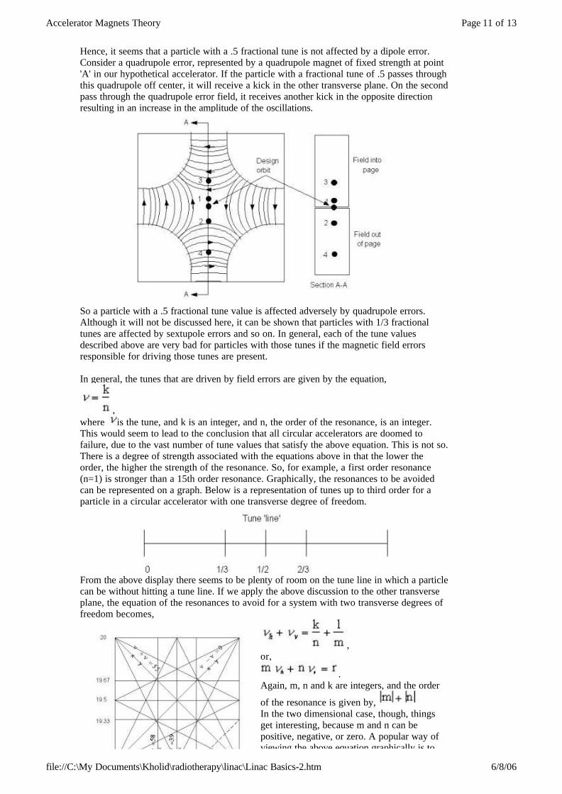
For those with electronics experience, the above diagrams may closely resemble Lissajous figures.The tune of a circular accelerator is a design parameter determined by the location and number of quadrupoles. This fixes a natural tune of the accelerator, but does not necessarily fix the tune that the accelerator will operate at, but only defines a region in which the tune can be varied. For example, the Tevatron during collider run typically has a horizontal tune of 19.58. By using the quadrupole trim magnets, the tune can be varied over a large range. The Tevatron, for instance, can not run with a tune of 4.8. So, in summary, the design of an accelerator determines a horizontal and vertical tune which can be varied over a small range by trim quadrupoles. The above discussion would incorrectly lead one to assume that a circular accelerator can run at any tune value near the natural tune of the accelerator. This is in fact not true. There are fractional tune values that are not allowed due to an additive effect. An example will illustrate this effect. Assume that the tune of our hypothetical accelerator was an integer, so that the particle path traced the same path on every revolution. If a small kick from a dipole field error was present at point 'A', then after passing point 'A', the amplitude of the transverse oscillations would be larger. On successive passes past point 'A', the amplitude of the transverse oscillations would grow until the particle would hit the beampipe wall of the accelerator. So, one can surmise that having an integer value for the tune is not a good idea unless there are no dipole field errors in the whole accelerator, of which there are always some. Lets look at this dipole error scenario with an accelerator running at a tune of .5.
If a particle has a tune of fractional tune value of .5, then the same trajectory is traced out every other revolution in the accelerator. If there is a dipole error at point 'A', then on one revolution of the particle, it will see a kick to increase the oscillation, however on the next pass through the region, the kick would tend to reduce the oscillation.
Hence, it seems that a particle with a .5 fractional tune is not affected by a dipole error.
Accelerator Magnets Theory Page 11 of 13
file://C:\My Documents\Kholid\radiotherapy\linac\Linac Basics-2.htm 6/8/06
Hence, it seems that a particle with a .5 fractional tune is not affected by a dipole error. Consider a quadrupole error, represented by a quadrupole magnet of fixed strength at point 'A' in our hypothetical accelerator. If the particle with a fractional tune of .5 passes through this quadrupole off center, it will receive a kick in the other transverse plane. On the second pass through the quadrupole error field, it receives another kick in the opposite direction resulting in an increase in the amplitude of the oscillations.
So a particle with a .5 fractional tune value is affected adversely by quadrupole errors. Although it will not be discussed here, it can be shown that particles with 1/3 fractional tunes are affected by sextupole errors and so on. In general, each of the tune values described above are very bad for particles with those tunes if the magnetic field errors responsible for driving those tunes are present. In general, the tunes that are driven by field errors are given by the equation,
,where is the tune, and k is an integer, and n, the order of the resonance, is an integer.This would seem to lead to the conclusion that all circular accelerators are doomed to failure, due to the vast number of tune values that satisfy the above equation. This is not so. There is a degree of strength associated with the equations above in that the lower the order, the higher the strength of the resonance. So, for example, a first order resonance (n=1) is stronger than a 15th order resonance. Graphically, the resonances to be avoided can be represented on a graph. Below is a representation of tunes up to third order for a particle in a circular accelerator with one transverse degree of freedom.
From the above display there seems to be plenty of room on the tune line in which a particle can be without hitting a tune line. If we apply the above discussion to the other transverse plane, the equation of the resonances to avoid for a system with two transverse degrees of freedom becomes,
,or,
.Again, m, n and k are integers, and the order
of the resonance is given by, In the two dimensional case, though, things get interesting, because m and n can be positive, negative, or zero. A popular way of viewing the above equation graphically is to

Accelerator Magnets Theory Page 12 of 13
file://C:\My Documents\Kholid\radiotherapy\linac\Linac Basics-2.htm 6/8/06
viewing the above equation graphically is to create a two dimensional version of the tune line above. This is known as a tune diagram. Above is a tune diagram showing up to third order resonances.
It is left for the reader to determine why the dotted line in the above figure does NOT show up on the third order resonance tune diagram as a resonance line. So far the discussion of tune dealt primarily with one particle. In actuality, the accelerators accommodate billions of particles in a single acceleration cycle. What is meant then by the tune of such a large number of particles is the weighted average of the tunes. This is analogous to the distribution of kinetic energy of gas molecules in a room. It is easier to think of the tune distribution as a Gaussian distribution, although this may not always be the case.
With this spread in tune for a many particle system, the region in the tune diagram in which the accelerator will
be operated (the operating point) becomes very important. It is not feasible to place the operating point very close to a resonance line because of the finite 'width' of the tune.
The control of this tune width is the topic of the next section. In summary,
D. ChromaticityAs beam travels through the accelerator, there is a certain spread in the momentum of the beam, and hence a spread in the horizontal position of the beam. As this beam travels through the quadrupoles, the beam on the design orbit sees no focusing effect. Beam that is further from the design orbit experiences a stronger focusing effect. The result of this is that different particles see a different restoring force from the quadrupoles. This results in a different focusing force, and hence a different tune for particles with different momenta. This is analogous to the bending of white light through a lens or a prism. The different wavelengths of light get bent at different angles, resulting in different focal points. For the
Order (n) Tune
1 integer
2 1/2
3 1/3
4 1/4

Accelerator Magnets Theory Page 13 of 13
file://C:\My Documents\Kholid\radiotherapy\linac\Linac Basics-2.htm 6/8/06
wavelengths of light get bent at different angles, resulting in different focal points. For the beam, this results in a spread in tune due to a spread in momenta. To control this width, one can change the sextupole magnets in the accelerator, or more commonly called changing the chromaticity. The sextupole magnets control the tune spread by adjusting the spread in momentum that the beam has. Reducing the momentum spread will also reduce the tune spread. Note that although it might seem at first glance to be very desirable to have a very narrow tune spread, this is not the case. Consider beam with a narrow distribution of tunes. If the average tune of this distribution drifts over a resonance line, then there will be a greater number of particles that will be affected by the resonance line, and -- depending on the strength of the line -- a large amount of beam may be lost. On the other hand, it is notdesirable to have a large tune spread either. The reason for this can be seen when another concept called the 'operating point' is considered.Ideally, one would want to have the tune of the beam to occupy a region of 'tune space' that is void of strong resonance lines. If the tune spread is too large, then some of the beam will straddle a resonance line and will be lost.