THEORY OF COUPLED-MODE SELF-EXCITED VIBRATION OF TAINTER · PDF fileTHEORY OF COUPLED-MODE...
30
678 THEORY OF COUPLED-MODE SELF-EXCITED VIBRATION OF TAINTER GATES Keiko Anami 1 , Noriaki Ishii 2 * and Charles W Knisely 3 *Corresponding Author: Noriaki Ishii, [email protected] The theoretical analysis of coupled-mode self-excited vibration of hydraulic gates is developed in the present paper. The theory is applied to the 87-ton Tainter gate at the Folsom Dam, which according to eyewitness testimony, experienced flow-induced vibrations and failed in l995. In its original design, the Folsom Tainter gate possessed two significant vibration modes. One mode was a whole gate rotation around the trunnion pin, while the second mode was a streamwise bending vibration of the skinplate. For certain upstream water levels, these two modes can couple with each other through hydrodynamic forces and inertia torques, producing self-excited vibration. The equations of motion for the small amplitude coupled-mode vibration are derived in non-dimensional form, revealing the non-dimensional parameters governing the vibrations and the hydrodynamic forces. The characteristics of this coupled-mode self-excited vibration are obtained through approximate numerical solutions, derived by iterative numerical calculations of the equations of motion. In addition, examination and physical explanations for vibration trajectories and energy transfer from the fluid motion to the gate vibration are presented. The theory, along with measured in-air frequencies, mode shapes and damping ratios, is used to generate stability diagrams of the original Folsom gate design. Keywords: Vibration, Flow-induced, Tainter gate, Coupled-mode, Self-excited, Equations of motion INTRODUCTION Tainter gates (also known as radial gates) are used frequently as crest gates on dam spillways for water level regulation. The design of these Tainter gates is such that the resultant ISSN 2278 – 0149 www.ijmerr.com Vol. 3, No. 4, October 2014 © 2014 IJMERR. All Rights Reserved Int. J. Mech. Eng. & Rob. Res. 2014 1 Department of Mechanical Engineering, Ashikaga Institute of Technology, 268, Omae-cho, Ashikaga, Tochigi 326-8558, Japan. 2 Department of Mechanical Engineering, Osaka Electro-Communication University, 18-8, Hatsu-chou, Neyagawa, Osaka 572-8530, Japan. 3 Department of Mechanical Engineering, Bucknell University, Lewisburg, PA 17837, USA. hydraulic load due to pressure exerted on the skinplate usually passes through the trunnion pin. In this manner, the hydraulic load is usually borne by the trunnion pin as shown in Figure 1. The effect of mechanical friction in Tainter Research Paper
Transcript of THEORY OF COUPLED-MODE SELF-EXCITED VIBRATION OF TAINTER · PDF fileTHEORY OF COUPLED-MODE...

678
Int. J. Mech. Eng. & Rob. Res. 2014 Keiko Anami et al., 2014
THEORY OF COUPLED-MODE SELF-EXCITEDVIBRATION OF TAINTER GATES
Keiko Anami1, Noriaki Ishii2* and Charles W Knisely3
*Corresponding Author: Noriaki Ishii, [email protected]
The theoretical analysis of coupled-mode self-excited vibration of hydraulic gates is developedin the present paper. The theory is applied to the 87-ton Tainter gate at the Folsom Dam, whichaccording to eyewitness testimony, experienced flow-induced vibrations and failed in l995. In itsoriginal design, the Folsom Tainter gate possessed two significant vibration modes. One modewas a whole gate rotation around the trunnion pin, while the second mode was a streamwisebending vibration of the skinplate. For certain upstream water levels, these two modes cancouple with each other through hydrodynamic forces and inertia torques, producing self-excitedvibration. The equations of motion for the small amplitude coupled-mode vibration are derived innon-dimensional form, revealing the non-dimensional parameters governing the vibrations andthe hydrodynamic forces. The characteristics of this coupled-mode self-excited vibration areobtained through approximate numerical solutions, derived by iterative numerical calculationsof the equations of motion. In addition, examination and physical explanations for vibrationtrajectories and energy transfer from the fluid motion to the gate vibration are presented. Thetheory, along with measured in-air frequencies, mode shapes and damping ratios, is used togenerate stability diagrams of the original Folsom gate design.
Keywords: Vibration, Flow-induced, Tainter gate, Coupled-mode, Self-excited, Equations ofmotion
INTRODUCTIONTainter gates (also known as radial gates) areused frequently as crest gates on damspillways for water level regulation. The designof these Tainter gates is such that the resultant
ISSN 2278 – 0149 www.ijmerr.comVol. 3, No. 4, October 2014
© 2014 IJMERR. All Rights Reserved
Int. J. Mech. Eng. & Rob. Res. 2014
1 Department of Mechanical Engineering, Ashikaga Institute of Technology, 268, Omae-cho, Ashikaga, Tochigi 326-8558, Japan.2 Department of Mechanical Engineering, Osaka Electro-Communication University, 18-8, Hatsu-chou, Neyagawa, Osaka 572-8530,
Japan.3 Department of Mechanical Engineering, Bucknell University, Lewisburg, PA 17837, USA.
hydraulic load due to pressure exerted on theskinplate usually passes through the trunnionpin. In this manner, the hydraulic load is usuallyborne by the trunnion pin as shown in Figure1. The effect of mechanical friction in Tainter
Research Paper

679
Int. J. Mech. Eng. & Rob. Res. 2014 Keiko Anami et al., 2014
gates is much less than in the other type ofgate, such as vertical lift gates, and a portionof the gate weight is also carried by thetrunnion pin, permitting the use of a relativelya small capacity hoisting motor and smoothoperation of the gate. For this reason, Taintergates are well suited for larger installations.
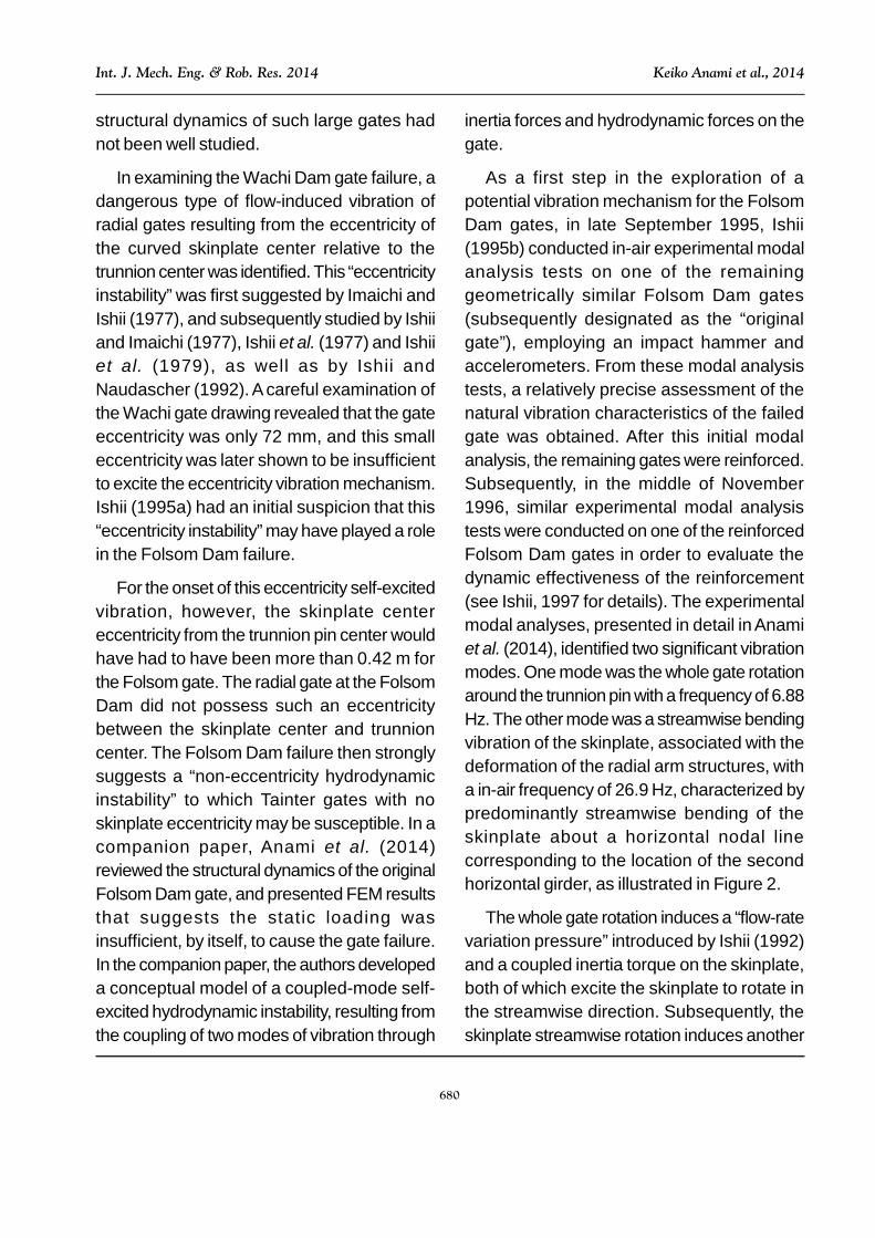
A drawing of a Tainter gate, previouslyinstalled at the Folsom Dam on the AmericanRiver near Sacramento, California is shownin Figure 1. The gate has a height of 15.5 m, awidth of 12.8 m and the curved skinplate radiusof 14.33 m. The whole gate mass is 87.03 ×10³ kg. According to an eyewitness account,one of these massive Tainter gatesexperienced flow-induced vibrations andfailed, early in the morning of July 17, 1995.The gate operator was on the catwalk justabove the gate to opening the gate. He said
he felt a small steady vibration starting up,initially very light, but then quickly intensifying.Upon his initial observation, the operatorpushed the stop button, thinking to close thegate. As he turned from the control panel, hesaw the one side of the gate moving slowly inthe downstream direction, rotating about theother side of the gate, like a large hingedgarage door, as detailed by Ishii (1995a).
In an earlier case, a Tainter gate, with aheight of 12 m, a width of 9 m, a radius of 13m and a mass of 37 × 103 kg at the WachiDam in Japan failed and was sweptdownstream about 140 m on July 2, 1967 (Ishiiet al., 1980). More than 30 years ago, thereview team for this gate failure in Japansuggested that flow-induced vibrations as apossible cause. However, at that time therewas no known vibration mechanism and the
Figure 1: Side View of the 87-ton Tainter Gate from the Folsom Dam in California,Showing Two Predominant Natural Vibration Modes
680
Int. J. Mech. Eng. & Rob. Res. 2014 Keiko Anami et al., 2014
structural dynamics of such large gates hadnot been well studied.
In examining the Wachi Dam gate failure, adangerous type of flow-induced vibration ofradial gates resulting from the eccentricity ofthe curved skinplate center relative to thetrunnion center was identified. This “eccentricityinstability” was first suggested by Imaichi andIshii (1977), and subsequently studied by Ishiiand Imaichi (1977), Ishii et al. (1977) and Ishiiet al. (1979), as well as by Ishii andNaudascher (1992). A careful examination ofthe Wachi gate drawing revealed that the gateeccentricity was only 72 mm, and this smalleccentricity was later shown to be insufficientto excite the eccentricity vibration mechanism.Ishii (1995a) had an initial suspicion that this“eccentricity instability” may have played a rolein the Folsom Dam failure.
For the onset of this eccentricity self-excitedvibration, however, the skinplate centereccentricity from the trunnion pin center wouldhave had to have been more than 0.42 m forthe Folsom gate. The radial gate at the FolsomDam did not possess such an eccentricitybetween the skinplate center and trunnioncenter. The Folsom Dam failure then stronglysuggests a “non-eccentricity hydrodynamicinstability” to which Tainter gates with noskinplate eccentricity may be susceptible. In acompanion paper, Anami et al. (2014)reviewed the structural dynamics of the originalFolsom Dam gate, and presented FEM resultsthat suggests the static loading wasinsufficient, by itself, to cause the gate failure.In the companion paper, the authors developeda conceptual model of a coupled-mode self-excited hydrodynamic instability, resulting fromthe coupling of two modes of vibration through
inertia forces and hydrodynamic forces on thegate.
As a first step in the exploration of apotential vibration mechanism for the FolsomDam gates, in late September 1995, Ishii(1995b) conducted in-air experimental modalanalysis tests on one of the remaininggeometrically similar Folsom Dam gates(subsequently designated as the “originalgate”), employing an impact hammer andaccelerometers. From these modal analysistests, a relatively precise assessment of thenatural vibration characteristics of the failedgate was obtained. After this initial modalanalysis, the remaining gates were reinforced.Subsequently, in the middle of November1996, similar experimental modal analysistests were conducted on one of the reinforcedFolsom Dam gates in order to evaluate thedynamic effectiveness of the reinforcement(see Ishii, 1997 for details). The experimentalmodal analyses, presented in detail in Anamiet al. (2014), identified two significant vibrationmodes. One mode was the whole gate rotationaround the trunnion pin with a frequency of 6.88Hz. The other mode was a streamwise bendingvibration of the skinplate, associated with thedeformation of the radial arm structures, witha in-air frequency of 26.9 Hz, characterized bypredominantly streamwise bending of theskinplate about a horizontal nodal linecorresponding to the location of the secondhorizontal girder, as illustrated in Figure 2.
The whole gate rotation induces a “flow-ratevariation pressure” introduced by Ishii (1992)and a coupled inertia torque on the skinplate,both of which excite the skinplate to rotate inthe streamwise direction. Subsequently, theskinplate streamwise rotation induces another

681
Int. J. Mech. Eng. & Rob. Res. 2014 Keiko Anami et al., 2014
large hydrodynamic force producing asignificant added mass effect, and the inertiatorque is fed back to excite the whole gaterotation. The pressure loading, correspondingto the large hydrodynamic force producing theadded mass effect, has been called the “push-and-draw pressure” by Anami and Ishii(1998a).
With the gate motion in each modegenerating a driving force for the other mode,the two vibration modes couple very effectivelywith each other through the hydrodynamicforces and inertia torques, resulting in a violentcoupled-mode self-excited vibration undercertain conditions. It is emphasized that thismechanism may potentially excite any Taintergate, even those with zero eccentricitybetween the trunnion center and the skinplatecenter.
Theoretical analysis of this potentiallydisastrous coupled-mode self-excitedvibration requires the calculation of the push-and-draw pressure induced by a streamwiserotation of the skinplate. The methodology forthis calculation was introduced by Anami andIshii (1998a). It was later carried outspecifically for the Folsom gate by Anami etal. (2012a). Subsequently, the theoreticaldevelopment requires a method to calculatethe in-water natural vibration frequency of theskinplate rotation. Such a method wasdocumented in Anami and Ishii (1998b). In alater publication, Anami et al. (2012b) providethe calculation of the in-water natural frequencyfor the skinplate of the Folsom Dam. Basedon the measured in-air natural frequency of26.9 Hz, Anami et al. (2012b) find the in-waternatural vibration frequency of the skinplate
Figure 2: Schematic View of Tainter Gate Low Frequency Skinplate Bending Mode in theStreamwise Vertical Direction, and 1/2 Wave-Length Mode in the Spanwise Direction

682
Int. J. Mech. Eng. & Rob. Res. 2014 Keiko Anami et al., 2014
bending mode for the Folsom Dam gate to be6.46 Hz under the conditions at the time offailure. The significant reduction in the bendingmode frequency stems directly from the hugeadded mass effect, and produces a relativelytight frequency coherence between theskinplate bending mode and the whole gaterotational vibration around the trunnion pin ata frequency of 6.88 Hz.
In this study, previously developedexpressions for push-and-draw pressure andflow-rate-variation pressure are applied to thecoupled-mode vibration of the Folsom DamTainter gate to derive the equations of motionassuming small amplitudes. The equations ofmotion are reduced to a non-dimensional form.The non-dimensional equations provideguidance on the appropriate non-dimensionalparameters, such as a reduced added mass,reduced fluid damping and excitationcoefficients for hydrodynamic forces, as wellas the water-to-gate mass ratio and themoment-of-inertia ratio for vibrations.Ultimately, based on the derived equations ofmotion, a closed energy cycleis presented,which predicts the susceptibility of the FolsomDam Tainter gate to the coupled-mode self-excited instability under the conditionsprevailing at the time of failure.
EQUATIONS OF MOTIONCoupled Torque of InertiaFigure 2 provides a three-dimensionalillustration of the skinplate bending vibration.In the streamwise vertical plane, the skinplateexhibits a low-frequency bending mode,essentially performing a rotational vibrationaround a horizontal nodal line, termed the“streamwise-rotation center line.” The counter-
clockwise rotation of the skinplate along thespanwise center line, as shown in Figure 2 withthe upstream reservoir to the right, isrepresented by. In the spanwise horizontalplane, the skinplate exhibits a half-wave-lengthbending mode shape with nodes at each end.Therefore, z, the rotational angle of theskinplate at a given spanwise distance Z fromthe spanwise center, can be approximated by
2/1/sin 0 WZz ...(1)
where W0 is the spanwise length of theskinplate, as shown in Figure 2.
A schematic view of the skinplate elementwith a small spanwise length of dZ is shown inFigure 3, where the element performs arotation around the trunnion pin, representedby , in addition to the streamwise counter-clockwise-rotation represented by z, with acounter clockwise rotation defined as positive.
These two rotational vibrations can veryeffectively couple with each other through theinertia forces on the skinplate, that is, throughthe so-called “coupled inertia torque.” Thecoupled inertia torque around the skinplaterotation center due to the whole gate rotationalvibration around the trunnion pin is representedby dM, while the coupled inertia torquearound the trunnion pin due to the skinplatestreamwise rotational vibration is denoted bydM. Each differential coupled inertia torquecan be obtained by integrating the moment dueto the inertia forces on the infinitesimalskinplate element.
A small cross-section of the skinplate isindicated by the small black differentialelement in Figure 3. The mass of thisdifferential element per the unit span is denotedby dm and the mass for the differential element

683
Int. J. Mech. Eng. & Rob. Res. 2014 Keiko Anami et al., 2014
with span dZ is dmdZ. Multiplying the massby the tangential accelerations R and zR
yields the tangential inertia forces(–dmdZ R ) and (–dmdZ zR ), which areshown as vectors in Figure 3. Here, R and R
represent the radii of rotation for eachvibration, that is, the distance from the trunnionpin and from the skinplate rotation center tothe skinplate differential element, respectively.The present analysis assumes small vibrations,and hence the centrifugal forces can beneglected as second order relative to thetangential forces.
The tangential inertia force due to the vibration has an arm length of R* from theskinplate rotation center, while the tangentialinertia force due to the vibration has an armlength of R /2 from the trunnion pin. Multiplying
each differential tangential inertia force by themoment arm to the center of rotation for thecomplementary vibration and then integratingeach differential tangential inertial momentover the whole skinplate with a spanwise lengthdZ yields the streamwise and up-and-downcoupled inertia torques dM and dM givenby the following expressions:
m
RRdmdZdM *
or dZWI
dM
0
...(2)
m
z
RRdmdZdM
2
or
dZWI
dM z
02
...(3)
The subscript “m”on the integral representsintegration over the spanwise-unit-length of the
Figure 3: Cross-Sectional View of Skinplate Performing Counterclockwise (Streamwise)Bending and Counterclockwise (Upward) Rigid-Body Rotational Vibrations
684
Int. J. Mech. Eng. & Rob. Res. 2014 Keiko Anami et al., 2014
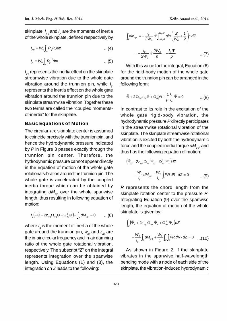
skinplate. I and I are the moments of inertiaof the whole skinplate, defined respectively by
m
dmRRWI *0 ...(4)
m
dmRWI 20 ...(5)
I represents the inertia effect on the skinplatestreamwise vibration due to the whole gatevibration around the trunnion pin, while I
represents the inertia effect on the whole gatevibration around the trunnion pin due to theskinplate streamwise vibration. Together thesetwo terms are called the “coupled moments-of-inertia” for the skinplate.
Basic Equations of MotionThe circular-arc skinplate center is assumedto coincide precisely with the trunnion pin, andhence the hydrodynamic pressure indicatedby P in Figure 3 passes exactly through thetrunnion pin center. Therefore, thehydrodynamic pressure cannot appear directlyin the equation of motion of the whole gaterotational vibration around the trunnion pin. Thewhole gate is accelerated by the coupledinertia torque which can be obtained byintegrating dM over the whole spanwiselength, thus resulting in following equation ofmotion:
02 2 Zaaa dMI ...(6)
where I is the moment of inertia of the wholegate around the trunnion pin, a and za arethe in-air circular frequency and in-air dampingratio of the whole gate rotational vibration,respectively. The subscript “Z” on the integralrepresents integration over the spanwiselength. Using Equations (1) and (3), theintegration on Z leads to the following:
/2W
/2W 00z
0
0
dZ21
WZsin
2WI
dM
I2W2WI 0
0...(7)
With this value for the integral, Equation (6)for the rigid-body motion of the whole gatearound the trunnion pin can be arranged in thefollowing form:
012 2
II
aaa ...(8)
In contrast to its role in the excitation of thewhole gate rigid-body vibration, thehydrodynamic pressure P directly participatesin the streamwise rotational vibration of theskinplate. The skinplate streamwise rotationalvibration is excited by both the hydrodynamicforce and the coupled inertia torque dM, andthus has the following equation of motion:
dZzazaaz 22
000 R dZdRPRI
WdMI
W
...(9)
R represents the chord length from theskinplate rotation center to the pressure P.Integrating Equation (9) over the spanwiselength, the equation of motion of the wholeskinplate is given by:
dZZ
zazaaz 22
000 Z RZdZdRPR
IWdM
IW
...(10)
As shown in Figure 2, if the skinplatevibrates in the spanwise half-wavelengthbending mode with a node of each side of theskinplate, the vibration-induced hydrodynamic

685
Int. J. Mech. Eng. & Rob. Res. 2014 Keiko Anami et al., 2014
pressure is naturally influenced by the half-wavelength bending vibration. Therefore, theintegration with respect to Z can be carriedout for all terms except for the hydrodynamicpressure term, resulting in the followingexpression:
22 aaa
022
2/
2/
0
0
dRPRdZII
IR
W
W
...(11)
where Equation (2) was substituted intoEquation (10).a and a represent the in-aircircular frequency and in-air damping ratio ofthe skinplate streamwise natural vibration,respectively.
Hydrodynamic PressureWhen the whole gate performs rotation aroundthe trunnion pin, the flow-rate beneath the gatevaries, producing the “flow-rate variationpressure”, Pr. When the circular-arc skinplateperforms streamwise rotational vibrations, theupstream water is pushed and drawn by thestreamwise movement of the boundary, thusproducing the “push-and-draw pressure”, Pb.If the movement of the lower edge of theskinplate is not in the tangential direction ofthe dam crest curve, as shown in Figure 3, anadditional flow-rate variation is induced by thestreamwise rotation of the skinplate,producing the “additional flow-rate-variation-pressure”, Pr. On these pressure terms, thesubscripts “r” and “b” represent the flow-ratevariation under the gate and the flow-boundarymovement due to skinplate vibration,respectively. The second subscripts, “ ” and“”, represent the upward rotation of the wholegate and the streamwise rotation of theskinplate, respectively. Assuming small
amplitude vibrations for both of the skinplatestreamwise rotational vibration and whole gaterotational vibration around the trunnion pin, andusing the superposition principle, the resultanthydrodynamic pressure fluctuation P due toboth vibrations occurring simultaneously isgiven by the summation of these pressurecomponents:
P = Pb + Pr + Pr ...(12)
Since the vibration amplitude in the half-wavelength mode is far smaller than thespanwise length of the skinplate, it is assumedhere that the hydrodynamic pressurecomponents are simply proportional to thestreamwise and tangential vibrationamplitudes of the lower-end of the skinplate.Each pressure component was analyzed, byapplying the potential theory developed byRayleigh (1945) for dissipative-wave radiationproblems (Ishii, 1992; and Anami et al.,2012b). The potential theory yields values ofpressure fluctuations that agree well withexperimental results (Anami et al., 2012b).The three hydrodynamic pressure componentscan, therefore, be reduced to the followingexpressions:
)2/1/(sin
/
00
WZRgP
ps
bb ...(13a)
02/
cf
rr Rc
gPp ...(13b)
)2/1/(sin2
/
00
WZkRcgP
psf
rr
(where k = –sins0) ...(13c)
Note thats0 is the angle of the streamwisevibration direction relative to the tangent to thedam crest, as shown in Figure 3; k is the press-

686
Int. J. Mech. Eng. & Rob. Res. 2014 Keiko Anami et al., 2014
2
FFp
FFpp a
rpa
rsr ...(14c)
In Equation (14b), p is the pressurecorrection coefficient that accounts for theinclination of the circular-arc skinplate relativeto the channel bed. The value of p can beobtained by model experiments, as describedin Anami et al. (2012b). In the presentformulation, the in-air vibration period 1/a ofthe whole gate vibration around the trunnionpin is adopted as the representative time scalefor non-dimensionalizing the time T; further, therotating angular amplitudes 0 and 0 areadopted as amplitude scales to reducevibration amplitudes, respectively:
00 /;/; Tt a ...(15)
F and Fa represent the Froude number andthe basic Froude number, defined by thefollowing expressions:
wgdF 0 and aa g
dF 0 ...(16)
which characterize the fluctuating flow fieldassociated with vibrations at circularfrequencies ofw in water anda in air. Theskinplate submergence depth is representedby d0.
The dimensionless pressure amplitudesrepresented by prs, prp, pbs and pbp in Equation(14) have been formulated as seriessummations (Ishii, 1992; and Anami et al.,2012b) as functions of the Froude number F,and the reduced height of the streamwise-rotation center, rs, defined by
rs = RS/d0 ...(17)
Subscripts “s” and “p” on the pressureamplitudes in Equation (14) represent the
shut coefficient, which takes on a negativevalue for a press-open device (as the skinplatemoves downward, the gate openingincreases), and a positive value for a press-shut device (as the skinplate movesdownward, the gate opening decreases). Thesymbol cf represents the instantaneous flow-rate-variation coefficient. In Equations (13), thewater head of each pressure fluctuation isdivided by a corresponding representativelength. The length used for the flow-rate-variation pressure [Equation (13b)] was themagnitude of the change in the gate-openingheight. For the push-and-draw pressure[Equation (13a)] and the additional flow-rate-variation pressure [Equation (13c)]), thecharacteristic length is the streamwisevibration amplitude of the skinplate at itsbottom end, since both depend on theskinplate rotation. The amplitudes of andare represented by 0 and 0, respectively.The radius of the skinplate is represented byRa. The length Rc is the rotation radius ofskinplate lower end about the trunnion pin, asshown in Figure 3. The length RS is rotationradius of the lower end of the skinplate aboutits horizontal streamwise-rotation center.
The dimensionless pressure fluctuationsdefined by Equations (13) can be ultimatelyreduced to summations of components inphase with the respective velocities andaccelerations, as given by the followingexpressions:
2
FFp
FFpp a
rpa
rsr ...(14a)
F
FpF
Fpp abp
abspb
2
...(14b)

687
Int. J. Mech. Eng. & Rob. Res. 2014 Keiko Anami et al., 2014
standing and progressive pressurecomponents, respectively.
Reduced Equations of MotionUsing the non-dimensional parametersintroduced in Equation (15), the equation ofmotion of the whole gate rotational vibrationaround the trunnion pin, given by Equation (8),can be reduced to the following form:
012*
Ia ...(18)
where * represents the angular amplituderatio of the whole gate rotational vibrationaround the trunnion pin to the skinplatestreamwise rotational vibration:
00* / ...(19)
In addition, using the hydrodynamicpressures given by Equations (12) and (13),as well as the non-dimensional variablesintroduced by Equation (15), the equation ofmotion for the skinplate streamwise rotationalvibration, Equation (11), can be written in thefollowing form:
*2
22 Ia
dyr
ypF s
ba
0
1
*2
11
dyr
ypFr
cs
rasa
f
0
12*1112
2
01120
12
dy
ryp
Fkc
sr
af
...(20)
where represents the in-air natural vibrationfrequency ratio of the skinplate streamwiserotational vibration to the whole gaterotational vibration around the trunnion pin:
aa / ...(21)
Further, I represents the ratio of thecoupled moment-of-inertia I to the skinplatemoment-of-inertia I, and rsa represents therotation radius ratio, defined respectively as
III / and cSsa RRr / (22)
In addition, is the mass ratio of therepresentative water mass to the skinplatemass given by:
20
20
/ SRIWd
...(23)
By substituting the non-dimensionalhydrodynamic pressures in the form given byEquations (14) into the equation of motion,Equation (20), one can arrive at the followingexpression:
mkcm fp 221
2212
affa F
ckc
asaf
safI Fr
cc
rm
c 222*
...(24)
where f represents the wave-radiationdamping ratio, as defined by
a
pf F
c2
...(25)
The symbols m and c are theequivalent added mass and the wave-radiationdamping coefficient due to the skinplatestreamwise rotational vibration, respectively.They are given as

688
Int. J. Mech. Eng. & Rob. Res. 2014 Keiko Anami et al., 2014
dyy0,pr
y11F1FΔm bs
0
1 s2ψ
...(26a)
dyypr
y11F1FΔc bp
0
1 sψ
...(26b)
The symbolsm andc are the equivalentadded mass and the fluid-excitation coefficientdue to the whole gate rotational vibration,respectively. They are given as
dypr
y11F1
2Δm rp
0
1 s2θ
...(27a)
dypr
yF
c rss
0
1
1112
...(27b)
In Equation (24), the equation of motion forthe skinplate streamwise rotational vibration,the second term on the right-hand side, the oneproportional to velocity, is most significant forstability. This term results from the flow-ratevariation and drives the coupled-mode self-excited vibration. The parameter f in thesecond term on the left-hand side representsthe wave-radiation damping effect due todissipative waves and is dependant upon thedissipative wave-radiation dampingcoefficient c. As the Froude numberincreases, the dissipative wave-radiationdamping coefficient c decreases rapidlyand takes on an almost zero value for largeFroude number. The parameter m in thefirst term on the left-hand side represents theadded mass effect of the fluid, whichsignificantly reduces the in-air natural vibrationfrequency when the gate vibrates in water.
The calculated values for the flow-inducedfactors m, c, m, and c are shown inFigure 4. All of these flow-induced factors arefunctions of the Froude number. As the Froudenumber increases, the reduced added mass
m decreases rapidly and is nearly zero forFroude numbers F larger than about 2. As aresult, the reduced added mass effect due tothe whole gate rotational vibration around thetrunnion pin has no effect on neither the wholegate vibration nor on the skinplate streamwiserotational vibration. When the Froude numberF is larger than about 10, the dissipative wave-radiation damping coefficient c alsoapproaches zero. In contrast, the fluidexcitation coefficient c increases rapidlyfrom zero and asymptotically approaches acomparatively large value, signifying acomparatively large fluid-excitation effect forsufficiently large Froude numbers. This is thesignificant factor which drives the self-excitedvibration of the coupled-mode vibrationsystem. In addition, the reduced added massm also increases rapidly from zero, andapproaches an asymptotic value at largeFroude numbers resulting in a significantfrequency reduction for the streamwiserotational vibration relative to its in-air value.
The equation of motion, Equation (24), forthe skinplate streamwise rotational vibrationwhen arranged in standard form with thecoefficient of '' equal to 1.0 becomes:
mkcm
Fc
kc
fp
affa
221
2
2
mkcm fp
221
2
mkcm
Frc
cr
mc
fp
asaf
safI
221
222
*
...(28)

689
Int. J. Mech. Eng. & Rob. Res. 2014 Keiko Anami et al., 2014
The coefficient of gives the in-water to in-air vibration frequency ratio nw in the followingform:
mkcm fpa
nwnw
221
...(29)
The denominatora represents the in-airvibration frequency of the whole gate rotationalvibration around the trunnion pin, which takeson essentially the same value as the in-waternatural vibration frequency, since no addedmass effect arises due to the whole gatevibration around the trunnion pin.
Using the in-air vibration frequency ratio aa / defined by Equation (22), nw
can also be expressed as follows:
nwnw ...(30)
where nw is the in-water to in-air vibrationfrequency ratio of the skinplate streamwisevibration:
mkcm fpa
nwnw
221
1
...(31)With these vibration frequency ratios, the
equation of motion for the skinplate, Equation(28), can be ultimately arranged as follows:
222 nwa
ffanwnw Fc
kc
asaf
safInw Fr
cc
rm
c 222
2*
...(32)
Figure 4: Equivalent Added Mass Coefficients, m and m, Wave-Radiation DampingCoefficient, c and Fluid-Excitation Coefficient, c, for Skinplate Vibration in the 1/2
Wave-Length Transverse (Horizontal) Bending Mode
690
Int. J. Mech. Eng. & Rob. Res. 2014 Keiko Anami et al., 2014
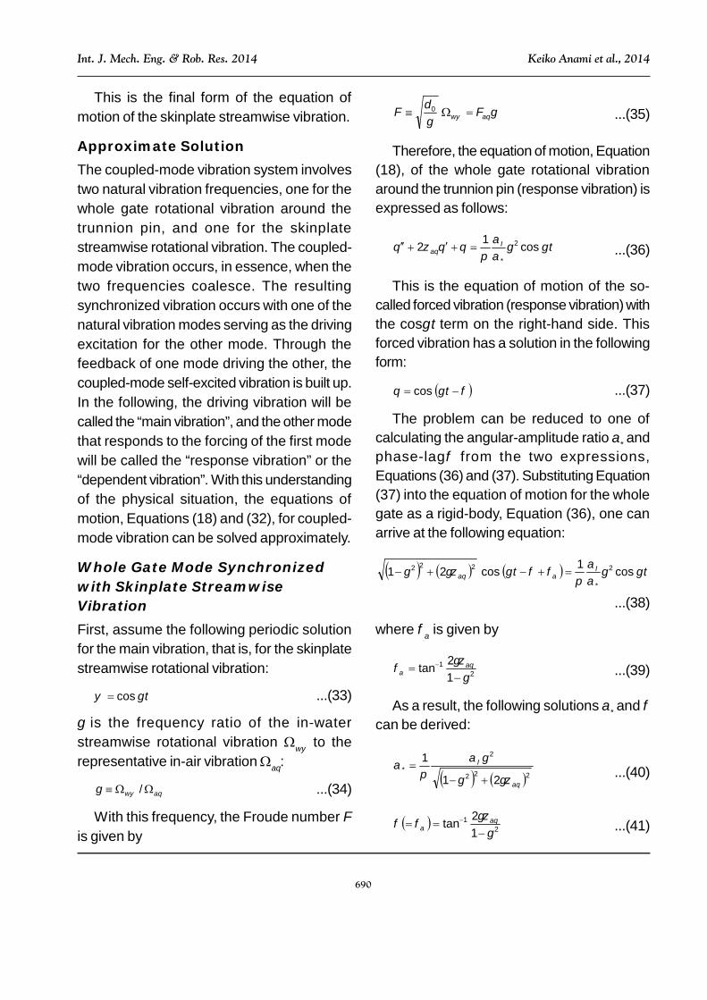
This is the final form of the equation ofmotion of the skinplate streamwise vibration.
Approximate SolutionThe coupled-mode vibration system involvestwo natural vibration frequencies, one for thewhole gate rotational vibration around thetrunnion pin, and one for the skinplatestreamwise rotational vibration. The coupled-mode vibration occurs, in essence, when thetwo frequencies coalesce. The resultingsynchronized vibration occurs with one of thenatural vibration modes serving as the drivingexcitation for the other mode. Through thefeedback of one mode driving the other, thecoupled-mode self-excited vibration is built up.In the following, the driving vibration will becalled the “main vibration”, and the other modethat responds to the forcing of the first modewill be called the “response vibration” or the“dependent vibration”. With this understandingof the physical situation, the equations ofmotion, Equations (18) and (32), for coupled-mode vibration can be solved approximately.
Whole Gate Mode Synchronizedwith Skinplate StreamwiseVibrationFirst, assume the following periodic solutionfor the main vibration, that is, for the skinplatestreamwise rotational vibration:
t cos ...(33)
is the frequency ratio of the in-waterstreamwise rotational vibration w to therepresentative in-air vibrationa:
aw / ...(34)
With this frequency, the Froude number Fis given by
aw FgdF 0 ...(35)
Therefore, the equation of motion, Equation(18), of the whole gate rotational vibrationaround the trunnion pin (response vibration) isexpressed as follows:
tIa
cos12 2
*
...(36)
This is the equation of motion of the so-called forced vibration (response vibration) withthe cos t term on the right-hand side. Thisforced vibration has a solution in the followingform:
tcos ...(37)
The problem can be reduced to one ofcalculating the angular-amplitude ratio * andphase-lag from the two expressions,Equations (36) and (37). Substituting Equation(37) into the equation of motion for the wholegate as a rigid-body, Equation (36), one canarrive at the following equation:
tt Ia
cos1cos21 2
*
222
...(38)
where is given by
21
12tan
a ...(39)
As a result, the following solutions * and can be derived:
222
2
*
21
1
a
I
...(40)
21
12tan
a ...(41)
691
Int. J. Mech. Eng. & Rob. Res. 2014 Keiko Anami et al., 2014
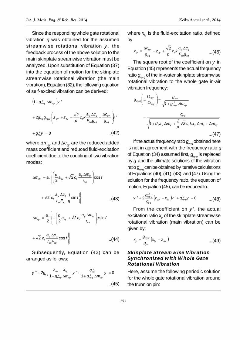
Since the responding whole gate rotationalvibration was obtained for the assumedstreamwise rotational vibration , thefeedback process of the above solution to themain skinplate streamwise vibration must beanalyzed. Upon substitution of Equation (37)into the equation of motion for the skinplatestreamwise rotational vibration (the mainvibration), Equation (32), the following equationof self-excited vibration can be derived:
mnw21
cF
ckc
affanwnw
22
02 nw ...(42)
where m and c are the reduced addedmass coefficient and reduced fluid-excitationcoefficient due to the coupling of two vibrationmodes:
cos22*
safI r
mcm
sin12asa
f Frc
c ...(43)
sin2
22*
safI r
mcc
cos2asa
f Frc
c ...(44)
Subsequently, Equation (42) can bearranged as follows:
011
2 2
2
2
mm nw
nw
nw
fa
...(45)
where f is the fluid-excitation ratio, definedby
a
fff Fc
kcc
2...(46)
The square root of the coefficient on inEquation (45) represents the actual frequencyratio w of the in-water skinplate streamwiserotational vibration to the whole gate in-airvibration frequency:
Δm1 2nw
nw
a
ww
ΔmΔmkc22Δm1 fp
...(47)If the actual frequency ratio w obtained here
is not in agreement with the frequency ratio of Equation (34) assumed first, w is replacedby , and the ultimate solutions of the vibrationratio w can be obtained by iterative calculationsof Equations (40), (41), (43), and (47). Using thesolution for the frequency ratio, the equation ofmotion, Equation (45), can be reduced to:
02 22
wfa
w...(48)
From the coefficient on ’, the actualexcitation ratio of the skinplate streamwiserotational vibration (main vibration) can begiven by:
af
w ...(49)
Skinplate Streamwise VibrationSynchronized with Whole GateRotational VibrationHere, assume the following periodic solutionfor the whole gate rotational vibration aroundthe trunnion pin:

692
Int. J. Mech. Eng. & Rob. Res. 2014 Keiko Anami et al., 2014
t cos ...(50)
where is the frequency ratio of in-waterrotational vibration around the trunnion pinw
to the representative in- air vibrationa:
aw / ...(51)
Using the in-water vibration frequencyw,the Froude number F is given by
aw FgdF 0 ...(52)
Using Equation (50), the right-hand side ofthe equation of motion, Equation (32), for theskinplate streamwise vibration can bearranged as follows:
Right-hand-side
tcos
rΔm
c22
2
safI
2nw*
tsinFrΔc
c2asa
f
0* cos tf ...(53)
where f and the phase-lag 0 are givenrespectively by
2
2 222
asaf
2
safInw Fr
cc
rm
cf
...(54)
safI
asaf
rm
c
Frc
c
22
2tan 1
0 ...(55)
Substituting Equation (53) into the right-hand side of the equation of motion, Equation(32), the following equation of motion for the
forced vibration (the response vibration) canbe obtained:
affanwnw F
ckc22
0*2 cos tfnw ...(56)
The solution of this forced vibration can beassumed to be of the following form:
0cos t ...(57)
where the angular-amplitude ratio * andphase-lag are given by
2
222*
221
affanwnwnw F
ckc
f
...(58)
221
22tan
nw
affanwnw F
ckc
...(59)
Since the responding skinplate streamwisevibration was obtained for the main wholegate vibration , it is necessary to analyze thefeedback process to the main whole gatevibration. Representing ” in the equation ofmotion, Equation (18), of the main whole gatevibration in terms of ” and ’, respectively,the following equation of motion for the self-excited vibration system can be derived:
0sincos12 00*
Ia
...(60)
which can be reduced ultimately to the followingexpression:
021 cm a ...(61)

693
Int. J. Mech. Eng. & Rob. Res. 2014 Keiko Anami et al., 2014
where m and c are the reduced addedmass and the reduced dissipative wave-radiation damping coefficient due to thecoupling of two vibration modes:
0*
cos1 Im ...(62)
0*
sin21 Ic ...(63)
Therefore, the equation of motion, Equation(61), can be arranged as follows:
01
11
2
mmfa ...(64)
where f is the fluid-excitation ratio:
cf ...(65)
The square root of the coefficient of inEquation (64) gives the in-water to in-airvibration frequency ratio w for the whole gaterotation around the trunnion pin:
ma
ww
11
...(66)
If this frequency ratio w is not inagreement with the frequency ratio whichwas first assumed in Equation (51), w isreplaced by , and the ultimate solution of thevibration ratio w can be obtained by iterativecalculations of Equations (58), (59), (62), and(66). Using the solution of frequency ratio, theequation of motion, Equation (64), can beexpressed in the following form:
02 22 wfaw ...(67)
From the coefficient on ’, the actualexcitation ratio of the whole gate rotationalvibration (main vibration) can be obtained asfollows:
afw ...(68)
Finally, the dynamic stability criteria can begiven by the following conditions that forcethe actual excitation ratio and to benegative:
a>f (when synchronized with theskinplate streamwise vibration) ...(69)
a>f (when synchronized with the wholegate rotational vibration) ...(70)
where a and a are the damping ratiosnecessary for the skinplate streamwisevibration and for the whole gate rotation to bedynamically stable, respectively.
Characteristics of Coupled-ModeSelf-Excited VibrationThe approximate solutions are calculatedspecifically for the case of Folsom Dam Taintergate. The major specifications of FolsomTainter gate at the time of failure are shown inTable 1. The average gate opening B was0.762 m, 5.7% of the water depth d0 of 13.26m, and hence it can be treated as a small gateopening. The moment of inertia of the gate wascalculated from the mass and dimensions ofeach component. The spanwise (i.e.,horizontal) nodal line of the skinplate, that is,the skinplate streamwise rotation center heightRS was 9.6 m. Values of the followingparameters were obtained from theexperimental modal analyses on a survivingoriginal Folsom gate (see Ishii et al., 2010 fordetails): the damping ratios of the whole gatevibration and the skinplate streamwisevibration, 0.012 and 0.002; the press-openangle of the lower end of the skinplate, 8.5°;and, the natural frequency of the skinplatestreamwise vibration, 26.9 Hz.

694
Int. J. Mech. Eng. & Rob. Res. 2014 Keiko Anami et al., 2014
The corresponding non-dimensional factorsfor the Folsom gate are shown in Table 2. Thegate inclination coefficient is a value obtainedfrom model tests for the gate inclined at 20° inthe downstream direction. The instantaneousflow-rate coefficient cf is a value also obtainedfrom the model tests. The press-shut coefficient
k was calculated from Equation (13). Thewater-to-gate mass ratio was 113,evidencing the light-weight design of the gate.The fluid-excitation coefficient c and theadded mass m are values obtained fromFigure 4, where it was assumed that theFroude number takes a value larger than about
10, which is generally true forfull-scale gates.
Calculated results for theapproximate solutions ofequations of motion are shownin Figure 5. It was assumed thatthe whole gate in-air vibrationfrequency a was unknown,while the skinplate streamwisein-air vibration frequency a
has been given as 26.9 Hz. In allfigures, the abscissa is the
Table 1: Major Specifications of Folsom Dam Tainter Gate
depth of upstream channel dr 14.02 m
gate opening B 0.762 mdepth over the gate bolttom d0 13.26 m
inclination angle of gate bottom to water surface Θs 9.5°
in-air natural vib. freq. of upward vib. Ωaθ 6.88 Hz
in-air natural vib. freq. of streamwise vib. Ωaψ 26.9 Hz
in-air damping ratio for upward vib ζaθ 0.012
in-air damping ratio for streamwise vib. ζaψ 0.002
rotation center height RS 9.6 m
press-open angle Θs0 8.5°
rotation rasius of skinplate lower end Rc 13.4 m
Fieldtest
conditions
gate height ― 15.5 m
spanwise length of skinplate W0 12.8 m
radius of skinplate Ra 14.33 m
gate mass ― 87 ton
whole gate around trunnion pin Iθ 1.31×10⁷ kgm2
skinplate around its rotation center Iψ 1.61×10⁶ kgm2
product of inertia of skinplate Iψ θ 1.27×10⁶ kgm2
Gatedimensionsand mass
Momentof
inertia
depth ratio (β*≡dr/d0) β* 1.01
reduced rotation center height (rs≡RS/d0) rs 0.72
rotation radius ratio (rsa≡RS/Rc) rsa 0.77
moment-of-inertia ratio (αI≡Iψ/Iθ) αI 0.123
moment-of-inertia ratio of skinplate (αIψ≡Iψ θ/Iψ) αIψ 0.79
water to gate mass ratio (αψ≡ρd02W0/(Iψ/RS
2)) αψ 129
instantaneous flow-rate-coefficient cf 0.72
pressure correction coefficient δp 1.0
basic Froude number Faψ 196 g/dF aa 02
Table 2: Non-Dimensional Factors for Calculations

695
Int. J. Mech. Eng. & Rob. Res. 2014 Keiko Anami et al., 2014
Figure 5: Approximate Solutions for Coupled-Mode Self-Excited Vibration of FolsomDam Tainter Gate: (a) Vibration Frequency Ratio; (b) Fluid Excitation Ratio;
(c) Phase-Lag; (d) Vibration Angle Amplitude Ratio; (e) Press-Shut Trajectories;(f) Press-Open Trajectories
696
Int. J. Mech. Eng. & Rob. Res. 2014 Keiko Anami et al., 2014
frequency ratio nw(=nw/a) of the in-waterstreamwise natural vibration of the skinplateto the in-air whole gate vibration around thetrunnion pin. When this frequency ratio takeson a value of 1.0, the in-water coupled-modevibrations of the skinplate streamwise andwhole gate vibrations are in resonance.
Figure 5a shows the in-water to in-airfrequency ratio w (= w/a) of the wholegate vibration around the trunnion pin and thefrequency ratio w(=w/a) of the skinplatestreamwise in-water vibration to the wholegate in-air vibration around the trunnion pin.The ratio w takes on a value of about 1.0,which indicates that the in-water frequency issame as the in-air frequency for the whole gatevibration around the trunnion pin, because ofno added mass effect on this mode of vibration.In contrast, w takes on almost the samevalue as nw of the abscissa, that is, theskinplate streamwise in-water vibration occursat its in-water natural vibration frequency. Itshould be noted here that the vibrationssynchronize with the skinplate streamwisevibration natural frequency in the abscissarange of nw<1.0 as shown by the solid line,while for nw>1.0 the vibrations synchronize withthe whole gate natural vibration frequency. Bothof the frequency ratios w and w show atendency to decrease slightly near theresonance state at nw=1.0.
Figure 5b shows the fluid-excitation ratiosf and f, representing the dynamic instability.If the fluid-excitation ratio is a positive value,energy flows to the structural vibration, resultingin a dynamically unstable state. When theabscissa is smaller than 1.0 (nw<1.0; nw
<a), f takes on positive values (solid line),while f takes on negative values (dashed
line). Since the press-open angle s0 waspositive, f takes negative value with smallnw. Because of these excitation ratio values,the self-excited vibration synchronizes with theskinplate streamwise rotational vibration. Asa result, the vibration frequency synchronizeswith the lower in-water inherent frequency (w
=nw), and hence the frequency ratio w
takes the same value as the in-water naturalvibration frequency ratio nw of abscissa, asshown by the solid line in Figure 5a.
In contrast, when the abscissa value islarger than 1.0 (nw>1.0; nw>a), f takesnegative values (dashed line), while f takeson positive values (solid line). In this case, theself-excited vibration synchronizes with thewhole gate rotational vibration. As a result, thevibration frequency synchronizes with the lowerin-water inherent frequency (w=a), andhence the frequency ratio w always takes ona value of 1.0, as shown by the solid line inFigure 5a.
Special attention should be given to thefollowing aspects of Figure 5b:
• When the vibration frequency ratio on theabscissa is slightly different from theresonant state (slightly higher or lower than1.0), a large dynamic instability appears,
• Especially, when the vibration frequencyratio on the abscissa takes on a value ofabout 0.96 (slightly smaller than 1.0), anintense dynamic instability appears.
The dynamic instability characteristics,shown in Figure 5b, can be explained bydrawing the coupled-mode vibrationtrajectories. The calculated phase-lag andangular amplitude ratio * are shown inFigures 5c and 5d, respectively. The phase-

697
Int. J. Mech. Eng. & Rob. Res. 2014 Keiko Anami et al., 2014
lag, , is the phase-lag of the up-and-downvibration (taken as positive upward) at thebottom of the skinplate bottom end relative tothe streamwise vibration (taken as positive inthe upstream direction) at the same location.When the self-excited vibration synchronizeswith the skinplate streamwise rotationalvibration, is given by of Equation (41) and* by Equation (40), which are denoted hereby and *, respectively. When the self-excited vibration synchronizes with the wholegate rotational vibration, is given by (0–)in Equations (55) and (59), and * is given byEquation (58), and are here denoted as
and *, respectively.
Figures 5e and 5f show the coupled-modevibration trajectories drawn using the and* data corresponding to each filled data point(denoted as “p” to “u”) in Figures 5a to 5d.When the fluid-excitation ratio takes on positivevalues as shown by points “p” to “s”, thevibration trajectories are typical of a “press-shut device”, as shown in Figure 5e. To thecontrary, when the fluid-excitation ratios takeon negative values as shown by points “t” and“u”, the vibration trajectories are typical of a“press-open device”, as shown in Figure 5f.
Multiplying the equation of motion, Equation(32), for skinplate streamwise rotationalvibration by d and then integrating, theenergy equation can be derived. The integralof the ’ term (due to the flow-rate variation)indicates there is a great amount of energy,either supplied or consumed. The energysupply E per cycle of vibration is given by
cyclecycle
dtdE11
...(71)
Therefore, when ’ and ’ have the samesigns, the energy is supplied. Conversely,
when they have the opposite signs, the energyis consumed. In the case of a press-shutdevice, ’ and ’ have the same signs inalmost all domains, thus supplying energy fromthe fluid to the vibration and thus inducing thedynamic instability, as shown by the solid linein Figure 5b. To the contrary, in the case of apress-open device, ’ and ’ have oppositesigns in almost all domains, thus consumingenergy from the vibration to the fluid and thusresulting in strong dynamic stability, as shownby the broken line in Figure 5b. The energytransfer will be again considered in detail inthe subsequent section.
Furthermore, regarding the press-shuttrajectories in Figure 5e, one may understandthat as the vibration trajectory becomes flat,or as the inclination approaches 45°, theenergy supply becomes larger. This can beexplained as follows: Assume the streamwisedisplacement x, of the skinplate bottom endand the up-and-down displacement y, can berepresented by the following expressions:
tFFrx
aps coscos0 ...(72a)
t
FFry
aps cossin0 ...(72b)
With these two expressions, Equation (71)yields the following result:
cycle1dtE
ΔcosFF2Θsinr
21dtxy
aps
20
1cycle
...(73)
From this expression, the energy supplybecomes largest, when the trajectoryinclination ps is 45° and when the trajectorythickness is zero.

698
Int. J. Mech. Eng. & Rob. Res. 2014 Keiko Anami et al., 2014
Examining the vibration trajectories inFigure 5e on the basis of the aboveinformation, one may infer that point “q,” withan inclination of nearly 45° and a comparativelyflat trajectory, is the most unstable case asshown in Figure 5b. In addition, point “r”, witha “thicker” trajectory (i.e., not as flat as for “q”)has a reduced energy supply, resulting in amoderate instability. Points “p” and “s” bothhave flat trajectories, but the inclination for “p”is too small and that for point “s” is too steepfor effective cross-coupling and in both casesthe resulting instability is weak.
Energy Transfer from VibrationTrajectoriesThe fundamental mechanism producing thevibration trajectories shown in Figures 5e and5f and the energy transfer between the fluidand structural vibration are examined in thissection. The two synchronization cases will beconsidered separately.
Coupled-Mode VibrationSynchronized with the SkinplateStreamwise VibrationWhen the circular-arc skinplate performsstreamwise rotational vibration, the whole gateis forced to vibrate around the trunnion pin bythe coupled inertia torque. The coupled inertiatorque appeared on the right-hand side of theequation of motion, Equation (18). Thiscoupled inertia torque on the right-hand sideforces the whole gate to vibrate around thetrunnion pin. Then, the component of thisexciting force in the up-and-down direction, dueto the coupled inertia torque, is illustrated bythe dashed lines in Figure 6a, where theabscissa is the streamwise vibrationdisplacement with positive values (the right-hand side) corresponding to the upstream
direction. The exciting force attains its upwardmaximum, just when the skinplate moves toits most upstream position. The up-and-downvibration responds to this excitation, subjectto Equation (18) with an appropriate phase-lag.
When the natural vibration frequency ratiois in the range where nw<1.0, the phase-lagtakes on a value from 0° to 90°. Since thewhole gate rotational vibration around thetrunnion pin has quite a small damping ratio,however, the phase-lag takes on a small valuenear zero, as shown by the small arrow alongthe abscissa. Thus, the maximum upwardvibration response appears when the skinplatehas moved just slightly downstream from itsmost upstream position, as shown in Figure6a. Consequently, the vibration trajectory in thiscase results in a very thin press-shut trajectory.The trajectory shows counter-clockwiserotation.
Now consider corresponding energy flowfor the streamwise rotational vibration. Theequation of motion of the streamwiserotational vibration is given by Equation (32).The first term of the right-hand siderepresents the inertia torque due to thecoupling and the second term represents thetorque due to the flow-rate variation pressure,both of which force the skinplate to vibrate inthe streamwise direction. Then, the resultantexciting force in the streamwise direction dueto these torques is typically illustrated by thesolid line in Figure 6b, where the exciting forcedue to the inertia torque is shown by the dottedline① and the exciting force due to the flow-rate variation pressure is shown by ②. Thedotted line marked by ② shows the excitingforce when the skinplate moves downward.

699
Int. J. Mech. Eng. & Rob. Res. 2014 Keiko Anami et al., 2014
This exciting force would then appear in theopposite direction when the skinplate movesupward. Figure 6c shows both the vibrationtrajectory and the resultant excitation force.The red lines of the vibration trajectory showwhen the resultant excitation force suppliesenergy to the streamwise vibration, while theblue lines show when the vibration energy isconsumed. As is clear from Figure 6c, thesupplied energy is far larger than theconsumed energy, thus inducing the intensedynamic instability observed for point “q” inFigure 5b.
When the natural vibration frequency ratiois in nw>1.0, the phase-lag takes on a valuefrom 90° to 180°. Since the damping ratio of
the whole gate rotational vibration around thetrunnion pin is quite small, the phase-lag takeson a large value near 180°. Then, when theskinplate comes to its most downstreamposition, the maximum upward vibrationresponse appears, as shown in Figure 6d. Asa result, the vibration trajectory in this caseshows a thin press-open trajectory. Thetrajectory has a counter-clockwise rotation.
Figure 6e shows both the press-opentrajectory and the resultant excitation force. Theenergy consumption region, shown by the bluelines, is far larger than the energy supply shownby the red. As a result, when the trajectorycorresponds to a press-open device, thesystem exhibits strong dynamic stability with
Figure 6: Vibration Trajectory Formation and Energy Supply, When Synchronized withthe Streamwise Rotational Vibration of Circular-Arc Skinplate: (a) Vibration Trajectoryat nw<1.0; (b) Exciting Forces:① Coupled inertia force;② Flow-Rate Variation Fluid
Force; (c) Energy Supply by Resultant Force to Streamwise Vibration, at nw<1.0;(d) Vibration Trajectory at nw>1.0; (e) Energy Supply by Resultant Force to
Streamwise Vibration, at nw>1.0

700
Int. J. Mech. Eng. & Rob. Res. 2014 Keiko Anami et al., 2014
no chance of coupled-mode vibration, as inpoint “u” in Figure 5b.
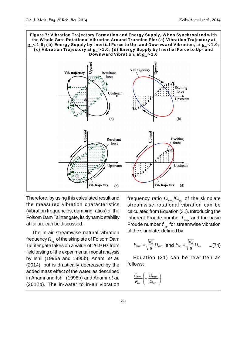
Coupled-Mode VibrationSynchronized with the Whole GateRotational VibrationWhen the whole gate performs rotationalvibration around the trunnion pin, the coupledinertia torque of the skinplate and the torquedue to the flow-rate variation pressure areinduced, thus forcing the circular-arc skinplateto vibrate in the streamwise direction. Thesetorques appear on the right-hand side ofequation of motion, Equation (32). Thestreamwise resultant exciting force due tothese torques is illustrated in Figure 6b andagain by the dashed line in Figure 7a. Themaximum exciting force in the downstreamdirection appears with a phase-lag between90° and 180° from the most upward positionof the skinplate. This streamwise excitingforce induces the maximum vibrationresponse in the downstream direction,however with a phase-lag which isdetermined by Equation (32).
When the natural vibration frequency rationw<1.0, that is, when the natural vibrationfrequency a of the main vibration is higherthan the natural vibration frequencynw of theresponse vibration, the downstream maximumvibration response appears with a phase-lagof about 180°, as shown by the arrows alongthe vertical axis in Figure 7a. As a result, thevibration trajectory shows a thick press-opencharacteristic, as illustrated by the solid line inFigure 7a. The trajectory has a clockwiserotation.
Figure 7b helps explain why the whole gaterotational vibration cannot gain energy by such
vibration. The coupled inertia torque of theright-hand side of the equation of motion,Equation (18), induces the up-and-downvibration of the skinplate. The upward inertiaforce becomes largest when the skinplatereaches its most upstream position, as shownin Figure 6a and again by the dotted line inFigure 7b. The energy supply lines shown inred are far smaller than the energyconsumption lines shown in blue. Thus, thesystem is dynamically stable, as shown bypoint “t” in Figure 5b.
When the natural vibration frequency rationw>1.0, that is, when the natural vibrationfrequency a of the main vibration is lowerthan the natural vibration frequencynw of theresponse vibration, the downstream maximumvibration response appears with a phase-lagof almost 0°, as shown by small arrows alongthe vertical axis in Figure 7c. As a result, thevibration trajectory shows a thick press-opencharacteristic, as illustrated in Figure 7c. Thetrajectory shows a counter-clockwise rotation.
Figure 7d shows both of the vibrationtrajectory and the resultant excitation force,where the energy supply region shown in redis far larger than the energy consumptionregion shown in blue. Thus, the vibration resultsin the dynamic instability shown by point “r”shown in Figure 5b.
Instability of the Folsom Gate forConditions at FailureThe fluid-excitation ratios for the Folsom DamTainter gate under its failure conditions weretheoretically calculated, as shown in Figure 5b.The ordinate represents the damping rationeeded to prevent the dynamic instability, thatis, so-called the “stability damping ratio”.
701
Int. J. Mech. Eng. & Rob. Res. 2014 Keiko Anami et al., 2014
Therefore, by using this calculated result andthe measured vibration characteristics(vibration frequencies, damping ratios) of theFolsom Dam Tainter gate, its dynamic stabilityat failure can be discussed.
The in-air streamwise natural vibrationfrequencya of the skinplate of Folsom DamTainter gate takes on a value of 26.9 Hz fromfield testing of the experimental modal analysisby Ishii (1995a and 1995b), Anami et al.(2014), but is drastically decreased by theadded mass effect of the water, as describedin Anami and Ishii (1998b) and Anami et al.(2012b). The in-water to in-air vibration
frequency ratio nw/a of the skinplatestreamwise rotational vibration can becalculated from Equation (31). Introducing theinherent Froude number nw and the basicFroude number a for streamwise vibrationof the skinplate, defined by
nwnw gdF 0 and aa g
dF 0 ...(74)
Equation (31) can be rewritten asfollows:
a
nw
a
nw
FF
Figure 7: Vibration Trajectory Formation and Energy Supply, When Synchronized withthe Whole Gate Rotational Vibration Around Trunnion Pin: (a) Vibration Trajectory at
nw<1.0; (b) Energy Supply by Inertial Force to Up- and Downward Vibration, at nw<1.0;(c) Vibration Trajectory at nw>1.0; (d) Energy Supply by Inertial Force to Up- and
Downward Vibration, at nw>1.0
702
Int. J. Mech. Eng. & Rob. Res. 2014 Keiko Anami et al., 2014
)(22)(1
1
nwfnwp FmkcFm
...(75)
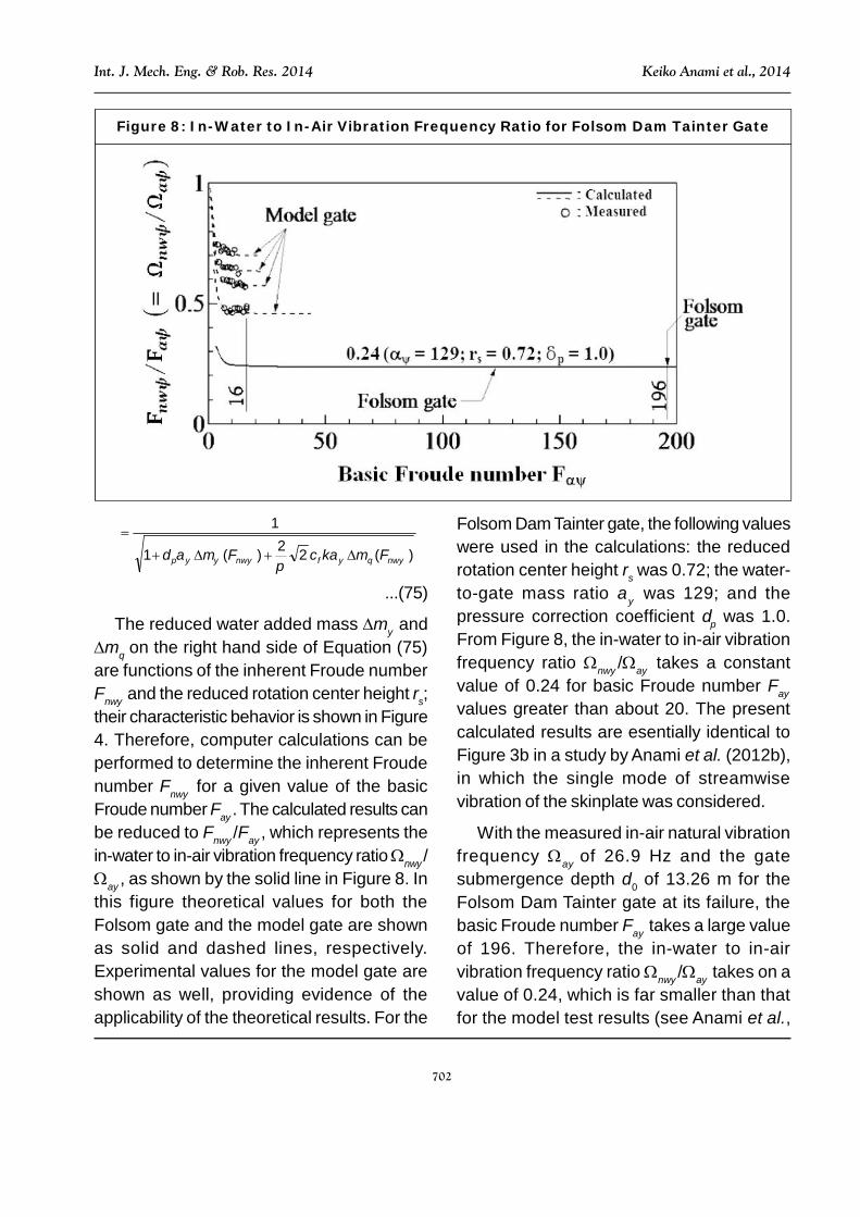
The reduced water added mass m andm on the right hand side of Equation (75)are functions of the inherent Froude numberFnw and the reduced rotation center height rs;their characteristic behavior is shown in Figure4. Therefore, computer calculations can beperformed to determine the inherent Froudenumber Fnw for a given value of the basicFroude number Fa. The calculated results canbe reduced to Fnw/Fa, which represents thein-water to in-air vibration frequency rationw/a, as shown by the solid line in Figure 8. Inthis figure theoretical values for both theFolsom gate and the model gate are shownas solid and dashed lines, respectively.Experimental values for the model gate areshown as well, providing evidence of theapplicability of the theoretical results. For the
Folsom Dam Tainter gate, the following valueswere used in the calculations: the reducedrotation center height rs was 0.72; the water-to-gate mass ratio was 129; and thepressure correction coefficient p was 1.0.From Figure 8, the in-water to in-air vibrationfrequency ratio nw/a takes a constantvalue of 0.24 for basic Froude number Fa
values greater than about 20. The presentcalculated results are esentially identical toFigure 3b in a study by Anami et al. (2012b),in which the single mode of streamwisevibration of the skinplate was considered.
With the measured in-air natural vibrationfrequency aof 26.9 Hz and the gatesubmergence depth d0 of 13.26 m for theFolsom Dam Tainter gate at its failure, thebasic Froude number Fa takes a large valueof 196. Therefore, the in-water to in-airvibration frequency rationw/a takes on avalue of 0.24, which is far smaller than thatfor the model test results (see Anami et al.,
Figure 8: In-Water to In-Air Vibration Frequency Ratio for Folsom Dam Tainter Gate

703
Int. J. Mech. Eng. & Rob. Res. 2014 Keiko Anami et al., 2014
2012b), shown by dashed lines in Figure 8.This is because the Folsom Tainter gate hasa water-to-gate mass ratio of 129, farlarger than the value of 2.45 to 14.8 for modelgate testing. The ratio of 0.24 for Folsom Damgate means the in-water vibration frequencywas slightly less than ¼ of the measured in-air natural vibration frequencya of 26.9 Hz,or more precisely 6.46 Hz. It is important tonote here that the frequency of streamwisebending is just slightly smaller than the in-airnatural vibration frequencya of 6.88 Hz forthe whole gate vibration around the trunnionpin. The resulting frequency ratio nw(=nw/a ) takes on a value of 0.94, just slightlysmaller than 0.96 at which the maximuminstability occurs. The measured in-airdamping ratio a of 0.002 of the skinplatestreamwise vibration is plotted on the stabilitycurve in Figure 9. For this mode of vibration,
with nodes along the sides of the gate, thedamping due to the side seals plays no role inthe streamwise bending vibration. Thedifference between the fluid dynamic excitationratio and the existing structural damping ratiois about 0.049, indicating an additional 5%damping would be needed to stabilize thegate. Increases in damping due to water havebeen included in the theory. As a result, onemay conclude that the dynamic condition of theFolsom Dam Tainter gate under the prevailingconditions at the moment of failure wassituated in the intense dynamic instabilityregion. This dynamic condition indicates thegate was readily susceptible to coupled-modevibration, which would induce a violentcoupled-mode vibration synchronized with theskinplate streamwise rotational bendingvibration, which would serve as the mainvibration at the incipient failure.
Figure 9: Dynamic Instability for the Failed Tainter Gate at the Folsom Dam

704
Int. J. Mech. Eng. & Rob. Res. 2014 Keiko Anami et al., 2014
CONCLUSIONBased on experimentally determined dynamiccharacteristics for the Folsom Dam Taintergate and using previously derived andvalidated expressions for pressure loadingand added mass effects, equations of motionwere derived for the two predominant vibrationmodes believed to have played a role in theFolsom gate failure. An approximate, iterativemethod of solution was employed to solve thetwo coupled equations. From the solutions,dynamic stability diagrams were derived.
The resulting solution demonstrates theexistence of two regions of instability, one inwhich the frequency of the skinplate bendingmode is just slightly less than the naturalfrequency of the rigid-body mode. In this regionthe skinplate bending acts as the main drivingforce and the rigid body rotation is theresponse mode. This is the most unstablesituation. The second region of instabilityoccurs when the frequency of the skinplatebending mode is just slightly higher than thatof the rigid body rotation. In this region therigid-body motion is the driving force and thebending mode is the response vibration. In thisregion, instability is still evident, but its intensityis reduced relative to that of the first region.
On the basis of this analysis, the FolsomDam was shown to possess a strong dynamicinstability for the conditions that pertained atthe instant of gate failure. There is every reasonto believe that this coupled-mode self-excitedinstability could well have played a very strong(if not dominant) role in the failure of theFolsom gate.
More importantly, the theory provides anassessment tool to determine the susceptibilityof any Tainter gate to this coupled-mode self-
excited instability. The necessary inputs arethe gate and sill geometry (from the drawingsfor the installation), the expected range ofdepth of the upstream reservoir, the skinplatein-air natural vibration characteristics(frequency, mode shape and damping ratio,usually from experimental modal analysis) forthe lowest frequency bending mode of theskinplate, and the rigid-body rotationalfrequency and damping ratio.
ACKNOWLEDGMENTFinancial support was provided by a Grant-in-Aid for Science Research of Japan Societyfor the Promotion of Science.
REFERENCES1. Anami K and Ishii N (1998a), “In-Water
Streamwise Vibration of Folsom DamRadial Gates in California”, Proceedingsof 1998 ASME Pressure Vessels andPiping Conf., Vol. 363, pp. 87-93.
2. Anami K and Ishii N (1998b), “In-Air andIn-Water Natural Vibrations of FolsomDam Radial Gate in California”,Proceedings of 11 th InternationalConference on Experimental Mechanics,Experimental Mechanics 1, in Allison(Ed.), pp. 29-34, Rotterdam, Balkema.
3. Anami K, Ishii N and Knisely C W (2012a),“Pressure Induced by Vertical Planar andInclined Curved Weir Plates UndergoingStreamwise Rotational Vibration”, J.Fluids and Structures, Vol. 29, pp. 35-49.
4. Anami K, Ishii N and Knisely C W (2012b),“Added Mass and Wave RadiationDamping for Flow-Induced RotationalVibrations of Skinplate”, J. Fluids andStructures, Vol. 35, pp. 213-228.

705
Int. J. Mech. Eng. & Rob. Res. 2014 Keiko Anami et al., 2014
5. Anami K, Ishii N and Knisely C W (2014),“Retrospective Considerations ofVibration Mechanism for Folsom DamTainter Gate Failure”, Intern. J. Mech.Engineering and Robotics Research,Vol. 3, No. 4.
6. Imaichi K and Ishii N (1977), “Instability ofan Idealized Tainter Gate System WithoutDamping Caused by Surface Waves onthe Backwater of Dam”, Bulletin of theJapan Society of Mechanical Engineers,Vol. 20, No. 146, pp. 963-970.
7. Ishii N (1992), “Flow-Induced Vibration ofLong-Span Gates (Part I: ModelDevelopment)”, J. Fluids and Structures,Vol. 6, pp. 539-562.
8. Ishii N (1995a), “Folsom Dam GateFailure Evaluation and Suggestions”,Report Submitted to US Bureau ofReclamation, August 24.
9. Ishii N (1995b), “Folsom Dam GateFailure Evaluation Based on ModalAnalysis and Suggestion”, ReportSubmitted to US Bureau of Reclamation,November 8.
10. Ishii N (1997), “Dynamic StabilityEvaluation for Folsom Dam Radial Gate
and its Inherent Non-EccentricityInstability”, Report Submitted to USBureau of Reclamation, July 17.
11. Ishii N and Imaichi K (1977), “WaterWaves and Structural Loads Caused bya Periodic Change of Discharge from aSluice Gates”, Bulletin of the JapanSociety of Mechanical Engineers ,Vol. 20, No. 6, pp. 998-1007.
12. Ishii N, Imaichi K and Hirose A (1977),“Instability of Elasticity Suspended TainterGate System Caused by Surface Waveson the Upstream Channel of a Dam”,ASME Journal of Fluids Engineering,Vol. 99-4, pp. 699-708.
13. Ishii N, Imaichi K and Hirose A (1979),“Dynamic Instability of Tainter Gates”,Practical Experiences with Flow-InducedVibrations, in E Naudascher and D ORockwell (Eds.), pp. 452-460, Springer,Berlin.
14. Ishii N and Naudascher E (1992), “ADesign Criterion for Dynamic Stability ofTainter Gates”, J. Fluids and Structures,Vol. 6, pp. 67-84.
15. Rayleigh J W S (1945), The Theory ofSound, Vol. 2, pp. 4-8, Dover, New York.
706
Int. J. Mech. Eng. & Rob. Res. 2014 Keiko Anami et al., 2014
B: discharge gate opening
cf: instantaneous flow-rate variation coefficient
d0: skinplate submergence depth
dM, dM: coupled moment
F: Froude number
Fa, Fa: basic Froude number
Fnw: inherent Froude number
g: acceleration due to gravity
I: moment-of-inertia of whole gate rotation around trunnion pin
I: moment-of-inertia of skinplate streamwise rotation
I: coupled moment-of-inertia
k: press-shut coefficient
P, Pb, Pr, Pr: hydraulic pressure
pb, pr, pr: reduced hydrodynamic pressure
pbs, prs: amplitude of standing pressure wave component
pbp,prp: amplitude of progressive pressure wave component
Ra: length of radial arm
Rc: rotation radius of skinplate lower end
RS, rs: rotation center height
rsa: ratio of rotation radius
R: distance from skinplate rotation center to skinplate small area
T, t: time
W0: spanwise length
X: coordinate along undisturbed free surface toward upstream side
Y: upward coordinate along skinplate
Z: horizontal coordinate along skinplate from its center
*: vibration angular amplitude ratio
I, I: ratio of moment of inertia
: water-to-skinplate mass ratio
*: depth ratio
nw: ratio of in-water natural frequencies of coupled-mode vibration
nw: in-air to in-water natural frequency ratio of streamwise vibration
w: in-air to in-water natural frequency ratio of whole gate rotational vibration around trunnion pin
w: actual vibration frequency ratio of streamwise vibration to in-air rotational vibration around trunnion pin
: in-air vibration frequency ratio
APPENDIXNomenclature

707
Int. J. Mech. Eng. & Rob. Res. 2014 Keiko Anami et al., 2014
c: reduced fluid excitation coefficient due to coupling
c: reduced wave-radiation damping coefficient due to coupling
C,c: wave-radiation damping coefficient
I: corrected moment of inertia
m, m: reduced added mass
m, m: reduced added mass due to coupling
p: pressure correction coefficient
a: in-air damping ratio (without coupling)
a: in-air damping ratio of rotational vibration around trunnion pin
a: in-air damping ratio of streamwise rotational vibration
f, f: wave-radiation damping ratio
w: in-water streamwise damping ratio (without coupling)
: counter-clockwise rotation angle of whole gate rotation around trunnion pin
0,0: amplitude of and
ps: press-shut angle of vibration trajectory
s0: geometric press-open angle
f, f: fluid excitation ratio
, : actual excitation ratio
,: counter-clockwise rotation angle of skinplate streamwise vibration
a: in-air natural vibration frequency ratio (without coupling) [rad/s]
a: in-air natural vibration frequency of whole gate rotation around trunnion pin
a: in-air streamwise natural vibration frequency ratio [rad/s]
w: in-water vibration frequency ratio (without coupling) [rad/s]
w: in-water vibration frequency of rotational vibration around trunnion pin [rad/s]
nw: in-water streamwise natural vibration frequency [rad/s]
w: in-water streamwise vibration frequency [rad/s]
Subcripts
( )a in-air
( )w in-water
( ) related to the rigid body rotation around the trunnion pin
( ) related to the skinplate bending mode
APPENDIX (CONT.)