Theory of BSS Synch
37
BSS Synchronisation DN04122254 Issue 4-0 en 22/02/2008 # Nokia Siemens Networks 1 (37) BSC3153 Nokia GSM/EDGE BSS, Rel. BSS13, BSC and TCSM, Rel. S13, Product Documentation, v.1
-
Upload
ashwani-kumar-singh -
Category
Documents
-
view
110 -
download
6
description
Theory of BSS Synch........................................
Transcript of Theory of BSS Synch

BSS Synchronisation
DN04122254Issue 4-0 en22/02/2008
# Nokia Siemens Networks 1 (37)
BSC3153Nokia GSM/EDGE BSS, Rel. BSS13, BSC andTCSM, Rel. S13, Product Documentation, v.1

The information in this document is subject to change without notice and describes only theproduct defined in the introduction of this documentation. This documentation is intended for theuse of Nokia Siemens Networks customers only for the purposes of the agreement under whichthe document is submitted, and no part of it may be used, reproduced, modified or transmitted inany form or means without the prior written permission of Nokia Siemens Networks. Thedocumentation has been prepared to be used by professional and properly trained personnel,and the customer assumes full responsibility when using it. Nokia Siemens Networks welcomescustomer comments as part of the process of continuous development and improvement of thedocumentation.
The information or statements given in this documentation concerning the suitability, capacity, orperformance of the mentioned hardware or software products are given “as is” and all liabilityarising in connection with such hardware or software products shall be defined conclusively andfinally in a separate agreement between Nokia Siemens Networks and the customer. However,Nokia Siemens Networks has made all reasonable efforts to ensure that the instructionscontained in the document are adequate and free of material errors and omissions. NokiaSiemens Networks will, if deemed necessary by Nokia Siemens Networks, explain issues whichmay not be covered by the document.
Nokia Siemens Networks will correct errors in this documentation as soon as possible. IN NOEVENT WILL NOKIA SIEMENS NETWORKS BE LIABLE FOR ERRORS IN THISDOCUMENTATION OR FOR ANY DAMAGES, INCLUDING BUT NOT LIMITED TO SPECIAL,DIRECT, INDIRECT, INCIDENTAL OR CONSEQUENTIAL OR ANY LOSSES, SUCH AS BUTNOT LIMITED TO LOSS OF PROFIT, REVENUE, BUSINESS INTERRUPTION, BUSINESSOPPORTUNITY OR DATA, THAT MAYARISE FROM THE USE OF THIS DOCUMENT OR THEINFORMATION IN IT.
This documentation and the product it describes are considered protected by copyrights andother intellectual property rights according to the applicable laws.
The wave logo is a trademark of Nokia Siemens Networks Oy. Nokia is a registered trademark ofNokia Corporation. Siemens is a registered trademark of Siemens AG.
Other product names mentioned in this document may be trademarks of their respective owners,and they are mentioned for identification purposes only.
Copyright © Nokia Siemens Networks 2008. All rights reserved.
2 (37) # Nokia Siemens Networks DN04122254Issue 4-0 en22/02/2008
BSS Synchronisation
Contents
Contents 3
List of figures 4
Summary of changes 5
1 BSS Synchronisation 71.1 Benefits for the operator 101.2 Benefits for applications 101.3 Benefits of BSS Synchronisation Recovery Improvement 11
2 Functional description of BSS Synchronisation 132.1 Operation and architecture of BSS Synchronisation 132.2 Recovery from loss of synchronisation when BSS11073: Recovery for
BSS and Site Synchronisation is activated 152.3 Recovery from loss of synchronisation when BSS20371: BSS
Synchronisation Recovery Improvement is activated 19
3 System impact of BSS Synchronisation 233.1 Required system elements 233.1.1 Required system elements for BSS11073: Recovery for BSS and Site
Synchronisation 233.1.2 Required system elements for BSS20371: BSS Synchronisation Recovery
Improvement 243.2 User interface 253.2.1 BSC MMI 253.2.2 BSC parameters 263.2.3 BTS parameters 283.2.4 LMU parameters 283.2.5 Alarms 293.2.6 Measurements and counters 303.3 Impact on Network Switching Subsystem (NSS) 303.4 Impact on NetAct products 303.5 Impact on interfaces 313.5.1 Abis 31
4 Implementing BSS Synchronisation 334.1 Overview of implementing BSS Synchronisation 334.2 Installing and commissioning 334.3 Configuring BSS Synchronisation 344.3.1 Configuring the LMUs 344.3.2 Configuring the BCFs 354.4 Activating BSS Synchronisation 354.5 Deactivating BSS Synchronisation 36
DN04122254Issue 4-0 en22/02/2008
# Nokia Siemens Networks 3 (37)
Contents

List of figures
Figure 1. Time slot coincidence 8
Figure 2. TSL synchronisation 9
Figure 3. TDMA frame and multiframe alignment with TSL Offset and FN Offset 9
Figure 4. The architecture of BSS Synchronisation at a BTS site 14
Figure 5. BSS synchronisation - LMU is the clock source 16
Figure 6. The LMU loses the GPS signal but continues to feed the clock signal 17
Figure 7. Behaviour after the timer 'Time from fix lost to clock out alarm' has expiredand the Recovery for BSS and Site Synchronisation software is inuse 18
Figure 8. Behaviour after the LMU reacquires the GPS fix. The system reconfiguresback to BSS synchronisation 19
Figure 9. Behaviour after the timer 'Time from fix lost to clock out alarm' has expired,when the BSS Synchronisation Recovery Improvement software inuse 20
Figure 10. Behaviour after the LMU reacquires the GPS fix, when the BSSSynchronisation Recovery Improvement software is in use 22
4 (37) # Nokia Siemens Networks DN04122254Issue 4-0 en22/02/2008
BSS Synchronisation

Summary of changes
Changes between document issues are cumulative. Therefore, the latestdocument issue contains all changes made to previous issues.
Changes made between issues 4-0 and 3-1
Descriptive information on the features Recovery for BSS and SiteSynchronisation and BSS Synchronisation Recovery Improvement hasbeen moved from the document Activating and Testing BSS11073:Recovery for BSS and Site Synchronisation and BSS20371: BSSSynchronisation Recovery Improvement to this document.
Changes made between issues 3-1 and 3-0
Information on the situation when external synchronisation is no longerneeded has been added in section BTS parameters, under section Userinterface, in chapter System impact of BSS Synchronisation.
Changes made between issues 3-0 and 2-0
In BSS Synchronisation, the subsection Benefits of BSS SynchronisationRecovery Improvement has been added.
In Functional description of BSS Synchronisation, Nokia LocationMeasurement Unit (LMUB) has been added.
Information on Flexi EDGE BTS has been added in chapters Functionaldescription of BSS Synchronisation and System Impact of BSSSynchronisation.
In System Impact of BSS Synchronisation and Implementing BSSSynchronisation, Nokia Location Measurement Unit has been added. Inaddition, information on the LMU parameters has been updated.
DN04122254Issue 4-0 en22/02/2008
# Nokia Siemens Networks 5 (37)
Summary of changes

6 (37) # Nokia Siemens Networks DN04122254Issue 4-0 en22/02/2008
BSS Synchronisation
1 BSS Synchronisation
BSS Synchronisation means that all the BTS sites in the synchronisationarea are fixed to a single external clock source, and the connections in thedifferent cells are aligned and synchronised at the time division multipleaccess (TDMA) burst level. In other words, the time slots in the radiointerface are constantly aligned. This enhances or enables some keyfeatures in the BSS system, such as Dynamic Frequency and ChannelAllocation (DFCA).
The purpose of Recovery for BSS and Site Synchronisation is to automatethe following processes:
. the recovery from the loss of LMU clock in order to change thechained cabinet into unsynchronised mode
. the recovery after the LMU clock becomes available for the cabinetsthat are being synchronised
. synchronisation recovery for Multi BCF site
Recovery for BSS and Site Synchronisation automates the recovery if theBTSs in the chain are synchronised and the clock signal is lost andregained. If the BSS or Site synchronisation of the chain has not beenactivated, the functionality of BSS and Site synchronisation that is used isat BSS10.5 level and the user has to lock and unlock the sites in thecorrect order to enable the synchronisation.
Conventionally, the achievable synchronisation in the GSM/EDGEsystems has been limited to the synchronisation of the transmitted radiointerface signals of the cells belonging to the same BTS site (one or moreBCFs). This is called site synchronisation, and it is possible because thedifferent logical cells within the same site use one single master clock.
DN04122254Issue 4-0 en22/02/2008
# Nokia Siemens Networks 7 (37)
BSS Synchronisation

Nokia's BSS synchronisation solution uses a global positioning system(GPS) time reference. Signals from the GPS satellites are received by thelocation measurement unit (LMU) at each BTS site. The LMU delivers theclock signal to the site's BCF cabinet(s). When all the clocks of thedifferent sites along the network are synchronised to a global timereference, BSS synchronisation is achieved.
Figure Time slot coincidence shows how the timeslots of different cellscause interference to each other.
Figure 1. Time slot coincidence
Figure TSL synchronisation presents the TDMA burst synchronisation (orTSL synchronisation). The guard period within each burst is the existingmargin in the GSM radio interface, which guarantees that a certainconnection only causes interference to the coincidentally broadcastconnections in other cells that are using a traffic channel (TCH) with thesame time slot (TSL) number.
Fully Interfered BurstsInterfering Burst
Synchronised Networks Non Synchronised Networks
8 (37) # Nokia Siemens Networks DN04122254Issue 4-0 en22/02/2008
BSS Synchronisation

Figure 2. TSL synchronisation
Once BSS synchronisation has been achieved, the further alignment ofthe transmitted downlink signals can be controlled by the settings of theTSL number and the frame number (FN) at every site. The TSL offsetand frame number offset parameters allow the shifting of the TDMAframes as shown in figure TDMA frame and multiframe alignment with TSLOffset and FN Offset.
Figure 3. TDMA frame and multiframe alignment with TSL Offset and FNOffset
FN offset is necessary for dealigning the SCH bursts of different cell sites.A mobile station (MS) needs to decode the base station identity code(BSIC) of the neighbouring cells to be measured and reported to thenetwork. The fast BSIC decoding benefits both cell reselection and
TS1 TS8
TS8
Guard Period (8.25 BP)
TS1
FN = n FN = n + 1
FN = n + 2*26 + 1
Site 1
Site 2
0 0
1 2
Timeslotoffset
FNoffset
FN = n + 2*26
0 1 2 3 4 5 6 7 0 1 2 3 4 5 6
7 0 1 2 3 4 5 6 7 0 1 2 3 4 5
DN04122254Issue 4-0 en22/02/2008
# Nokia Siemens Networks 9 (37)
BSS Synchronisation

handover processes. In a synchronised BSS, all SCH transmissionscoincide, making the BSIC decoding and neighbour measurements veryslow unless the frame numbers are dealigned. By distributing the FN offsetvalues evenly over the BSS so that each BTS site uses a different FN fromthe surrounding sites, the BSIC decoding performance is secured.
Similarly, the full rate (FR) SACCH performance may decrease in a fullysynchronised network. To avoid degradation, the TSL offset parametershifts the BTS timing so that the FR SACCH channels are not all sentsimultaneously. By distributing the TSL offset evenly over the network,SACCH performance degradation is avoided.
1.1 Benefits for the operator
Synchronising all the BTS sites in the network decreases the overlappingof the TDMA bursts and therefore minimises interference and the frameerror rate (FER). A higher tolerance to interference leads to betterperformance and makes the frequency reuse as well as the cell re-selection and handover processes more effective. It also makes the MSlocationing functionality more accurate.
When a burst causes interference to a serving connection, the servingconnection's FER increases as the overlapping between the interferingand serving bursts increases. When the overlapping is low, that is, below20%, the degradation is small. When the overlapping is over 40%, thetraining sequence is affected, and the degradation is as high as with fulloverlapping. This means that the worst performance case is the 50/50case, where the two serving connection bursts are 50% interfered by theinterfering burst (for more information, see figure Time slot coincidence).Simulation results have shown that in a synchronised network the overallgain over the network is 0.5 dB. This means that the network FER versusC/I performance will be enhanced by 0.5 dB.
1.2 Benefits for applications
Dynamic Frequency and Channel Allocation (DFCA)
BSS Synchronisation provides a platform for applications with very highperformance benefits. This can be measured as an increase in the spectralefficiency of the system. The performance increase can be traded for acapacity increase by tightening the effective frequency reuse. This trade-off is automatically controlled by DFCA.
10 (37) # Nokia Siemens Networks DN04122254Issue 4-0 en22/02/2008
BSS Synchronisation
The TSL level of synchronisation for the BTSs allows the BSC to get theprecise knowledge of the interference sources when a new channelassignment is to be performed. Combining this information with the timeslot and frequency usage data makes it possible to choose the optimumradio channel for the connection. DFCA receives the information availablein the BSC and retrieved from other BSCs when the system issynchronised. With this information, DFCA dynamically calculates the C/Iof all the TSL and frequency combinations potentially applicable to aconnection. Based on this, the BSC can make more efficient channel andfrequency allocations. By controlling the interference, and considering theinterference mitigation capabilities of the connection type, the spectralefficiency is maximised.
For more information, see Dynamic Frequency and Channel Allocationunder Feature descriptions/Radio network performance in the PDF view.
MAIO cluster planning
Synthesised radio frequency hopping (RF hopping) allows you to avoidlocal interference by using MAIO management. Typically, MAIOmanagement is used to avoid interference between the sectors of thesame BTS site since the base stations located in the same site normallyshare the same clock source. BSS Synchronisation makes a synchronisedframe clock signal available across the network, therefore allowing theexpansion of the MAIO management across the different sites. When allthe base stations sharing the same MA list and hopping sequence numberare synchronised with each other and are using the same frame number,then co-channel interference between any two TRXs can be avoided byallocating different MAIO offset values to them. Therefore MAIOmanagement can also be applied between BTS sites, making it possible toproduce the most optimised MAIO plans that shift the interference awayfrom the areas susceptible to interference.
1.3 Benefits of BSS Synchronisation RecoveryImprovement
The purpose of BSS Synchronisation Recovery Improvement is toautomate the recovery from the loss of LMU clock.
With the BSS Synchronisation Recovery Improvement software, the BTSsite continues in the BSS synchronised service even if the GPS coverageis lost for up to 24 hours. The BTS site also continues in the BSSsynchronised service throughout a LMU software update.
DN04122254Issue 4-0 en22/02/2008
# Nokia Siemens Networks 11 (37)
BSS Synchronisation

Related topics
. Test and activate. Radio network performance
. Activating and Testing BSS11073: Recovery for BSSand Site Synchronisation and BSS20371: BSSSynchronisation Recovery Improvement
. Operate and maintain. Nokia BSS Transmission Configuration
. Reference. Alarms
. Base Station Alarms (7000-7999). Commands
. MML commands. EF - Base Control Function Handling. EX - Position Based Services Handling
. Parameters. BSS Radio Network Parameter Dictionary
12 (37) # Nokia Siemens Networks DN04122254Issue 4-0 en22/02/2008
BSS Synchronisation

2 Functional description of BSSSynchronisation
2.1 Operation and architecture of BSS Synchronisation
Nokia BSS Synchronisation uses the GPS time reference forsynchronising all the BTS site clocks along the network to the same globalreference. The accuracy, stability, and reliability of synchronisation arecritical as they determine the efficiency of the whole solution. Theimplementation based on GPS time reference ensures very high accuracy.
Location Measurement Unit
The location measurement unit (LMU and LMUB) includes a GPS receiverand an interface to provide the GPS reference clock for the BTSs.
An LMU with a GPS antenna is placed at every BTS site in thesynchronisation area. Each LMU receives the reference clock signal fromthe GPS system and supplies the BTS site with a consistent frame clockadjusted by frame number offset and TSL offset. LMU receives theinformation on these two values from the BTS via the Q1 cable.
If the Q1 connection to the LMU or LMUB is not working, it means thatthere is no connection to the unit. No alarms will be raised from LMU, andthe LMUB clock output cannot be enabled or disabled because of siterestart or a synchronisation recovery task.
BTS
The LMU is the master clock for all the BCFs on the BTS site. The BCFnext to the LMU is called the master clock BCF. It passes the GPS clockreference signal from LMU through to the following BTS(s) in the chain,and uses the signal as a reference for its internal clocks. The figure belowshows how synchronisation is arranged at a BTS site.
DN04122254Issue 4-0 en22/02/2008
# Nokia Siemens Networks 13 (37)
Functional description of BSS Synchronisation

Figure 4. The architecture of BSS Synchronisation at a BTS site
BSC
The BSC controls the synchronisation recovery and supplies the LMUswith the values for frame number offset and TSL offset.
Furthermore, the BSC keeps track of the synchronisation status of thenetwork. You can query the status with the MML command EFL.
Master Clock BCF BCF
Abis Interface
FN OffsetTSL Offset
Alarms
Q1
LMU
INOUT
FN, FCLK
INOUT
FN, FCLK
BCF
IN
FN, FCLK
BSC
14 (37) # Nokia Siemens Networks DN04122254Issue 4-0 en22/02/2008
BSS Synchronisation

2.2 Recovery from loss of synchronisation whenBSS11073: Recovery for BSS and SiteSynchronisation is activated
The handling of the exception situation where the LMU loses the GPSsignal is fully automated. The synchronisation status of each BTS isavailable in the BSC.
If the GPS signal is lost, the LMU GPS alarm 8048 LOSS OF INCOMINGSIGNAL is triggered. In the case of LMU, the BTSs stay in BSSsynchronisation for up to 240 seconds (that is, 4 minutes) after this alarm.With LMUB, the value is up to 3540 seconds (that is, 59 minutes). If theLMU reacquires the GPS signal within this period, the synchronisedoperation continues uninterrupted.
If the GPS signal is not reacquired within the defined period (within 4minutes in case of the LMU, and within 59 minutes in case of the LMUB),the clock out alarm is set (alarm 7601/7602 for UltraSite/Flexi EDGE/MetroSite, and alarm 7876 for Talk-family).
If the LMU clock supply to the BCF chain is interrupted because of LMUrestart, the clock out alarm is set. A scenario of this is described in 3b and4.
A scenario of what happens when the LMU loses the GPS signal isdescribed below.
1. The system is in BSS synchronisation
. The LMU generates the frame clock signal from GPS reference andfeeds it to the BTS cabinets.
. The BSS Synchronisation mode indicator in the BSC shows'SYNCH' for these BCFs.
DN04122254Issue 4-0 en22/02/2008
# Nokia Siemens Networks 15 (37)
Functional description of BSS Synchronisation

Figure 5. BSS synchronisation - LMU is the clock source
2. LMU loses the GPS fix
. Alarm 8048 LOSS OF INCOMING SIGNAL is set.
. The BTS cabinets continue synchronised operation uninterrupted byrelying on the internal LMU oscillator, before the parameter 'Timefrom fix lost to clock out alarm', which is defined in LMU, expires. ForLMU, the default value, which is also the recommended value of theparameter, is 240 seconds (that is, 4 minutes). For LMUB, thedefault value, which is also the recommended value for theparameter, is 3540 seconds (that is, 59 minutes).
. The LMU oscillator slowly drifts away from the global BSSSynchronisation timing.
. The BCF chain is still considered to be in BSS Synchronisation.
clock
BCF
Slaveclock
LMU
GPS antenna
BCF
Slave
16 (37) # Nokia Siemens Networks DN04122254Issue 4-0 en22/02/2008
BSS Synchronisation

Figure 6. The LMU loses the GPS signal but continues to feed the clock signal
3a. LMU reacquires the GPS fix before the timer 'Time from fix lost toclock out alarm' in LMU has expired
. Alarm 8048 ‘LOSS OF INCOMING SIGNAL’ is cancelled.
. The LMU oscillator slowly drifts back to the global BSSSynchronisation timing.
. The synchronised operation of the BTS cabinets continuesuninterrupted.
3b. Timer 'Time from fix lost to clock out alarm' in the LMU expiresbefore it has regained the GPS fix – the system performssynchronisation recovery
. Clock out alarm (7601/7602 in UltraSite/Flexi EDGE/MetroSite and7876 in Talk-family) is set.
. The BSC performs forced handovers in all the BCFs of the chain tomove the traffic to the surrounding cells.
. The timer 'Time from clocks out to clock disable' in the LMU expiresand the LMU disables the clock feed.
. The BSC resets all the BCFs in the chain.
. The first BCF in the chain is configured to be the clock master for thechain.
clock
BCF
Slaveclock
GPS antenna
BCF
Slave
LMU
DN04122254Issue 4-0 en22/02/2008
# Nokia Siemens Networks 17 (37)
Functional description of BSS Synchronisation

. Alarm 7787 SYNCHRONIZATION IS MISSING is set to indicate that thechain has lost BSS synchronisation.
. The chain continues to operate in BTS site synchronisation.
. The synchronisation mode indicator in the BSC shows 'UNSYNCH'for these BCFs.
Figure 7. Behaviour after the timer 'Time from fix lost to clock out alarm' hasexpired and the Recovery for BSS and Site Synchronisationsoftware is in use
4. The LMU reacquires the GPS fix after synchronisationreconfiguration
. Alarm 8048 LOSS OF INCOMING SIGNAL is cancelled.
. The BSC performs forced handovers in all the BCFs of the chain tomove the traffic to the surrounding cells.
. The BSC resets the master clock BCFs.
. The BSC restarts the LMU frame clock output and the LMU starts tosupply the clock.
. The first BTS is configured back to slave clock mode.
. The BSC resets the other BCFs.
. Alarm 7787 SYNCHRONIZATION IS MISSING is cancelled.
clock
ResetBCF
Masterclock
GPS antenna
ResetBCF
Slave
LMU
18 (37) # Nokia Siemens Networks DN04122254Issue 4-0 en22/02/2008
BSS Synchronisation

. The BTS site is back in BSS synchronisation.
. The synchronisation mode indicator in the BSC shows again'SYNCH' for these BCFs.
Figure 8. Behaviour after the LMU reacquires the GPS fix. The systemreconfigures back to BSS synchronisation
2.3 Recovery from loss of synchronisation whenBSS20371: BSS Synchronisation RecoveryImprovement is activated
1. Timer 'Time from fix lost to clock out alarm' in the LMU expiresbefore it has regained the GPS fix – the system performssynchronisation recovery
. Clock out alarm (7601/7602) in UltraSite BTS or in Flexi EDGE BTS isset.
. The BSC requests locking the BSS synchronisation signal of the firstBCF of the chain to Abis reference clock. The BSC also sets thechain BCFs to 'ABIS SYNCH' mode.
. The first BCF in the chain disables the LMU’s clock feed.
clock
ResetBCF
Slaveclock
GPS antenna
ResetBCF
Slave
LMU
DN04122254Issue 4-0 en22/02/2008
# Nokia Siemens Networks 19 (37)
Functional description of BSS Synchronisation

. The BSS synchronised operation of the BTS cabinets continuesuninterrupted. The synchronisation recovery does not have anyeffect on ongoing calls or data traffic.
. The synchronisation mode indicator in the BSC shows 'ABISSYNCH' for the chain BCFs.
Note
If the BSS Synchronisation Recovery Improvement software isactivated, the unlocking or resetting the master clock BCF during the‘ABIS SYNCH’ mode causes a reset of all the other BCFs in the BCFchain to ‘UNSYNCH’ mode.
Figure 9. Behaviour after the timer 'Time from fix lost to clock out alarm' hasexpired, when the BSS Synchronisation Recovery Improvementsoftware in use
After receiving the alarm 7602, the BSC starts timing for how long theBCF chain is in the ‘ABIS SYNCH’ mode. If the BCF chain has beenin the ‘ABIS SYNCH’ mode for the time defined by the BSCparameter LMUSYN_LOSS_ALARM_LIMIT (the default value is onehour), the BSC sets the notice 7788 LONG LOSS OF LMUSYNCHRONISATION.
clock
GPS antenna
clock
BCF
Master
BCF
Slave
BSC
Abis
LMU
20 (37) # Nokia Siemens Networks DN04122254Issue 4-0 en22/02/2008
BSS Synchronisation

If the BCF chain has been in the ‘ABIS SYNCH’ mode for the timedefined by the PRFILE parameter LMUSYN_LOSS_RESET_LIMIT(the default value is 24 hours) after receiving the alarm 7602, then
1. The BSC performs forced handovers in all BCFs of the chainto move the traffic to the surrounding cells.
2. The BSC resets all the BCFs in the chain.
3. The first BCF in the chain is configured to be the clock masterfor the chain.
4. Alarm 7787 SYNCHRONIZATION IS MISSING is set toindicate that the chain has lost BSS synchronisation.
5. The chain continues to operate in BTS site synchronisation.
6. The synchronisation mode indicator in the BSC shows'UNSYNCH' for these BCFs.
2. The LMU reacquires the GPS fix when the chain BCFs are in ABISSYNCH mode
1. Alarm 8048 LOSS OF INCOMING SIGNAL is cancelled.
2. The BSC executes the recovery by requesting the chain BCFs tostart using the incoming synchronisation signal from LMU.
3. The BTS requests the LMU to start clock supply during the recoveryaction.
4. The BSS synchronised operation of the BTS cabinets continuesuninterrupted. The synchronisation recovery does not have anyeffect on ongoing calls or data traffic in the BCFs.
5. The synchronisation mode indicator in the BSC shows 'LMUSYNCH' for the chain BCFs.
DN04122254Issue 4-0 en22/02/2008
# Nokia Siemens Networks 21 (37)
Functional description of BSS Synchronisation

Figure 10. Behaviour after the LMU reacquires the GPS fix, when the BSSSynchronisation Recovery Improvement software is in use
3. The LMU reacquires the GPS fix when the alarm 7787SYNCHRONISATION MISSING is active
. If the PRFILE parameter SYNC_RECOV_ENABLED has the value‘TRUE’ and the alarm 8048 LOSS OF INCOMING SIGNAL is cancelled,the BSC automatically resets the chain BCFs to work in BSSsynchronised ('LMU SYNCH') mode as described in 4.
. If the PRFILE parameter SYNC_RECOV_ENABLED has the value‘FALSE’, and the alarm 8048 LOSS OF INCOMING SIGNAL iscancelled, the recovery is not executed and alarm 7787SYNCHRONIZATION IS MISSING stays active and the chain BCFsstay in unsynchronised ('UNSYNCH') mode.
clock
BCF
Slaveclock
GPS antenna
BCF
Slave
LMU
22 (37) # Nokia Siemens Networks DN04122254Issue 4-0 en22/02/2008
BSS Synchronisation

3 System impact of BSS Synchronisation
The system impact of BSS11073: Recovery for BSS and SiteSynchronisation and BSS20371: BSS Synchronisation RecoveryImprovement is specified in the sections below. For an overview, see BSSSynchronisation.
3.1 Required system elements
3.1.1 Required system elements for BSS11073: Recovery for BSS and SiteSynchronisation
The following network elements and software versions support Recoveryfor BSS and Site Synchronisation:
. Nokia BSC with S11 SW
. Nokia NetAct with OSS3.1 ED3 SW
. Nokia Location Measurement Unit (LMU) with 4.4 SW
. Nokia Location Measurement Unit (LMUB) with 1.0 CD1 SW
. Nokia UltraSite EDGE BTS with CX4.0-4 SW
. Nokia Flexi EDGE BTS with EP1.0 SW
. Nokia MetroSite EDGE BTS with CXM4.1 SW
. Nokia Talk-family BTS with DF7 SW, BCFB card and ABSAassembly (Nokia Flexitalk is not applicable)
Note that ABSA refers to Talk Intra&CityTalk cabinet rooftopconnector plate.
DN04122254Issue 4-0 en22/02/2008
# Nokia Siemens Networks 23 (37)
System impact of BSS Synchronisation

3.1.2 Required system elements for BSS20371: BSS SynchronisationRecovery Improvement
The following network elements and software versions support BSSSynchronisation Recovery Improvement:
. Nokia BSC with S11.5 CD3.0 SW
. Nokia NetAct with OSS4.0 (RAC CD 726)
. Nokia Location Measurement Unit (LMU) with 4.4 SW
. Nokia Location Measurement Unit (LMUB) with 1.0 CD1 SW
. Nokia UltraSite EDEG BTS with CX4.1 SW
. Nokia Flexi EDGE BTS with EP1.0 SW
Note
If the used NetAct release is not OSS4 (CD 726) or later, there arecompatibility limitations.
If NetAct OSS4 release does not have CD 726 installed:
. The value ‘LMU-ABIS’ of the parameter clock source showswrongly in the NetAct Radio Access Configurator (RAC) userinterface. In addition, when downloading from RAC to BSC, thevalue of the parameter clock source is unnecessarily changed to'NONE' (remove clock source). At this phase the BCF is blocked andthere is a service break to subscribers.
If NetAct is an earlier release than OSS4.0:
. The BSC hides the value ‘LMU-ABIS’ of the parameter clocksource from the NetAct RAC (if set with an MML command) andconverts the new value ‘LMU-ABIS’ into an existing value ‘LMU’. Inthis case the wrong value ‘LMU’ shows in the RAC user interface.
24 (37) # Nokia Siemens Networks DN04122254Issue 4-0 en22/02/2008
BSS Synchronisation

3.2 User interface
3.2.1 BSC MMI
The following MML command groups are related to BSS Synchronisation:
. Base Control Function Handling, command group EF.
. Position Based Services Handling, command group EX.
Example 1 shows the MML output of synchronisation configuration andsynchronisation mode of each BCF in the chain, command EFL.
Example 1. Recovery for BSS and Site Synchronisation software in use:
SYNCHRONISATION
CONFIGURATION IN BSC:
CLOCK SYNCH SYNCH ADM OP DFCA BSC-
SOURCE ENABLED MODE STA STATE MODE BSC
================= ====== ======= ======== === ====== ====== ====
MASTER BCF-0001 LMU T SYNCH U WO
BTS-0001 U WO DFCA OK
BTS-0002 U WO DFCA OK
BCF-0002 SYNCH U WO
BTS-0003 U WO DFCA OK
BTS-0004 U WO DFCA OK
BCF-0003 SYNCH U WO
BTS-0005 U WO DFCA OK
BTS-0006 U WO DFCA OK
COMMAND EXECUTED
Example 2. BSS Synchronisation Recovery Improvement software in use:
SYNCHRONISATION
CONFIGURATION IN BSC:
CLOCK SYNCH SYNCH ADM OP DFCA BSC-
SOURCE ENABLED MODE STA STATE MODE BSC
================= ======== ======= ========== === ====== ===== ====
MASTER BCF-0001 LMU-ABIS T LMU SYNCH U WO
BTS-0001 U WO DFCA OK
BTS-0002 U WO DFCA OK
BCF-0002 LMU SYNCH U WO
BTS-0003 U WO DFCA OK
BTS-0004 U WO DFCA OK
BCF-0003 LMU SYNCH U WO
DN04122254Issue 4-0 en22/02/2008
# Nokia Siemens Networks 25 (37)
System impact of BSS Synchronisation

BTS-0005 U WO DFCA OK
BTS-0006 U WO DFCA OK
COMMAND EXECUTED
3.2.2 BSC parameters
Location Measurement Unit Area (LMUA) radio network objectparameters
The following parameters are used for configuring the LMU for BSSsynchronisation with commands from the MML command group EX.
. LMUA ID
Identifies the LMU area.
. LMU equipment TRE ID
For an LMU, the equipment index is always 'Unspecifiedtransmission equipment'.
. LMU equipment BCF ID
Identifies the BCF to which the LMU is connected via Q1.
. frame number offset
. LMU TSL FN Offset
TSL offset is called LMU TSL FN Offset in BSC MML.
BCF radio network object parameters
The following parameters are used for configuring the BTS site for BSSsynchronisation with commands from the MML command group EF.
. clock source
Value 'LMU' is used for Recovery for BSS and Site Synchronisation.
Value 'LAB' is used for BSS Synchronisation RecoveryImprovement.
. synch enabled
Activates BSS synchronisation.
. slave BCF list
. master clock BCF identification
26 (37) # Nokia Siemens Networks DN04122254Issue 4-0 en22/02/2008
BSS Synchronisation
For descriptions of the parameters, see BSS Radio Network ParameterDictionary in Nokia BSC/TCSM Product Documentation.
PRFILE parameters
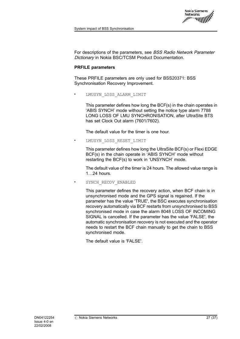
These PRFILE parameters are only used for BSS20371: BSSSynchronisation Recovery Improvement.
. LMUSYN_LOSS_ALARM_LIMIT
This parameter defines how long the BCF(s) in the chain operates in‘ABIS SYNCH’ mode without setting the notice type alarm 7788LONG LOSS OF LMU SYNCHRONISATION, after UltraSite BTShas set Clock Out alarm (7601/7602).
The default value for the timer is one hour.
. LMUSYN_LOSS_RESET_LIMIT
This parameter defines how long the UltraSite BCF(s) or Flexi EDGEBCF(s) in the chain operate in ‘ABIS SYNCH’ mode withoutrestarting the BCF(s) to work in ‘UNSYNCH’ mode.
The default value of the timer is 24 hours. The allowed value range is1…24 hours.
. SYNCH_RECOV_ENABLED
This parameter defines the recovery action, when BCF chain is inunsynchronised mode and the GPS signal is regained. If theparameter has the value 'TRUE', the BSC executes synchronisationrecovery automatically via BCF restarts from unsynchronised to BSSsynchronised mode in case the alarm 8048 LOSS OF INCOMINGSIGNAL is cancelled. If the parameter has the value 'FALSE', theautomatic synchronisation recovery is not executed and the operatorneeds to restart the BCF chain manually to get the chain to BSSsynchronised mode.
The default value is 'FALSE'.
DN04122254Issue 4-0 en22/02/2008
# Nokia Siemens Networks 27 (37)
System impact of BSS Synchronisation

3.2.3 BTS parameters
UltraSite BTSs
To use BSS Synchronisation, the BTS must be configured to use theexternal frame clock signal supplied by the LMU. With the BTS HWConfigurator, select Autodetected Clock Synchronisation in CabinetProperties. When external synchronisation is no longer needed, that is,for Independent mode, Autodetected Clock Synchronisation in BTSHW Configurator must be deselected.
For more information on using the BTS HW Configurator with UltraSiteBTS, see Commissioning UltraSite BTS in Nokia UltraSite BTS ProductDocumentation.
MetroSite BTSs
There are no configurable parameters for MetroSite.
Talk-family BTSs
The BCF card model must be 'BCFB', which has connections for externalclock signal. The BCFB card has jumpers with three possible settings:Master (generate and output clock), Slave (receive external clock), andIndependent (generates its own clock and does not use external signals).The BCFB card jumper settings should be set to “independent”, allowingthe BSC complete control and override of the BTS synchronisation modesetting.
3.2.4 LMU parameters
The following timer parameters can be seen with LMU Manager.
. time from fix lost to clocks out alarm
This parameter defines the time between GPS fix lost alarm (8048)and clock alarm (7601/7602 for UltraSite/Flexi EDGE/MetroSite or7876 for Talk-family BTSs). After this time, the BSC starts thesynchronisation recovery actions.
The default value for LMU is 240 s (4 min) and for LMUB it is 3540 s(59 min). This value should not be changed.
28 (37) # Nokia Siemens Networks DN04122254Issue 4-0 en22/02/2008
BSS Synchronisation

Note
When the BSS Synchronisation Recovery Improvement software is inuse and there is a long loss of GPS fix (GPS has been lost for morethan 15 hours) for some sites, it is recommended that you set the valueof the parameter to 120 seconds for the LMUs of these BCF chains.This ensures that the synchronisation accuracy of the BCFs in thechain is kept at the required level in case of a long loss of the GPS fix.
. time from clocks out alarm to clock disable
This parameter defines for how long the LMU keeps sending theframe clock signal after clock alarm 7602 or 7876. This time isrequired for forced handovers before the automatic recovery actionstake place.
The default value (60 s) is valid and it should not be changed.
This parameter is not used in case of BSS20371: BSSSynchronisation Recovery Improvement because no handover isperformed.
. automatic clock output
Because BSC controls the LMU clock output, the default value('OFF') must be retained for this parameter when BSSSynchronisation is used.
3.2.5 Alarms
Base Station Alarms
. 7601 BCF OPERATION DEGRADED (with the fault reason"External synchronisation signals disabled")
. 7602 BCF NOTIFICATION (with the fault reason "Externalsynchronisation signals disabled")
. 7787 SYNCHRONISATION MISSING
. 7788 LONG LOSS OF LMU SYNCHRONISATION (a notice type ofan alarm)
. 7875 EXTERNAL BTS SYNCHRONISATION SOURCE ISMISSING
. 7876 LMU: EXTERNAL SYNCHRONISATION SIGNALSDISABLED
DN04122254Issue 4-0 en22/02/2008
# Nokia Siemens Networks 29 (37)
System impact of BSS Synchronisation

Transmission Equipment Alarms
. 8048 LOSS OF INCOMING SIGNAL
. 8148 LMU RESET
3.2.6 Measurements and counters
There are no measurements or counters associated with BSSSynchronisation.
3.3 Impact on Network Switching Subsystem (NSS)
No impact.
3.4 Impact on NetAct products
NetAct Radio Access Configurator (RAC)
The BSS Synchronisation specific LMUA and BCF radio network objectparameters can be modified with RAC.
NetAct Monitor
The following alarms are related to BSS Synchronisation:
. 7601 BCF OPERATION DEGRADED (with the fault reason"External synchronisation signals disabled")
. 7602 BCF NOTIFICATION (with the fault reason "Externalsynchronisation signals disabled")
. 7787 SYNCHRONISATION MISSING
. 7788 LONG LOSS OF LMU SYNCHRONISATION (a notice type ofan alarm)
. 7875 EXTERNAL BTS SYNCHRONISATION SOURCE ISMISSING
. 7876 LMU: EXTERNAL SYNCHRONISATION SIGNALSDISABLED
. 8048 LOSS OF INCOMING SIGNAL
30 (37) # Nokia Siemens Networks DN04122254Issue 4-0 en22/02/2008
BSS Synchronisation

3.5 Impact on interfaces
3.5.1 Abis
The following messages in the Abis O&M interface are related to BSSSynchronisation:
. BTS_CLOCK_REQ
. BTS_LMU_FN_OFFSET_COMMAND
. BTS_LMU_FN_OFFSET_ANSWER
DN04122254Issue 4-0 en22/02/2008
# Nokia Siemens Networks 31 (37)
System impact of BSS Synchronisation

32 (37) # Nokia Siemens Networks DN04122254Issue 4-0 en22/02/2008
BSS Synchronisation

4 Implementing BSS Synchronisation
4.1 Overview of implementing BSS Synchronisation
The implementation of BSS Synchronisation consists of installing andcommissioning the equipment and configuring and activating thesynchronisation functionality. For more detailed information, see Activatingand Testing BSS11073: Recovery for BSS and Site Synchronisation andBSS20371: BSS Synchronisation Recovery Improvement in Nokia BSC/TCSM Product Documentation.
4.2 Installing and commissioning
BTSs
If there are several BCFs at the site, make sure that site synchronisationhas been implemented by connecting the BCFs with clock cables.
In addition, make sure that the BTSs have been configured to use theexternal frame clock signal supplied by the LMU as described under BTSparameters in System impact of BSS Synchronisation.
If there are different types of slave BCFs in the synchronisation chain, firstadd the Talk-family BTSs and then MetroSite BTS or UltraSite BTSs. Notethat Flexi EDGE BTS(s) can only be added after UltraSite or Flexi EDGEBTSs in the synchronisation chain. Only one MetroSite BTS or 'SharedBCF MetroSite chain' is allowed in a single clock chain.
The maximum number of clock-chained BCFs is nine. For more details onchaining and related clock cable connections, see Nokia UltraSite BTSProduct Documentation and Nokia MetroSite BTS ProductDocumentation.
DN04122254Issue 4-0 en22/02/2008
# Nokia Siemens Networks 33 (37)
Implementing BSS Synchronisation

LMU and LMUB
An LMU or LMUB with a GPS antenna is required at every BTS site. TheLMU and the LMUB are installed according to the BTS-type-specificinstructions. The LMU is commissioned with the LMU Manager and theLMUB is commissioned with the LMUB Manager.
When the BSS Synchronisation Recovery Improvement software(BSS20371) is in use and the GPS fix has been lost (the alarm 8048 isactive) in the LMU of the BSS synchronised BCF chain for more than 15hours, the value of the parameter time from fix lost to clocks out
alarm should be set to 120 seconds for the LMU and to 1800 seconds forthe LMUB. This ensures that the synchronisation accuracy of the BCFchains will be kept at the required level in case of a long (max 24 hours)loss of the GPS fix.
Note
When installing the LMU or LMUB, you should pay special attention tothe GPS antenna positioning so that there is clear visibility to severalGPS satellites.
The default value ('OFF') must be used for the parameter automaticclock output.
For more information, see the Nokia Location Measurement Unit UserManual documentation in Service Enablers category and Nokia LocationMeasurement Unit (LMUB) in Nokia UltraSite BTS Product Documentationin Radio Network Solutions category in NOLS Documentation Center.
4.3 Configuring BSS Synchronisation
Configuring BSS synchronisation is preparatory work for activation. It doesnot significantly affect network operation, so you can do it in advance.
4.3.1 Configuring the LMUs
To define the LMU area for BSS synchronisation, do the following:
34 (37) # Nokia Siemens Networks DN04122254Issue 4-0 en22/02/2008
BSS Synchronisation

1. Add the LMU to Q1 polling to allow LMU communication with theBTS (QWA, QUF).
The LMU or LMUB has to be added to the Q1 equipment list by usingthe QWA command in the BSC. To update the LMU or LMUB unit'stransmission equipment data to the BSC immediately, use the QUFcommand to start the checksum polling. Otherwise, the data isupdated by default once a day. For more information, see Managingthe transmission equipment statistics collection information in NokiaBSC/TCSM Product Documentation.
2. Check the LMU software (QWL).
For more information, see BSS Transmission Management in NokiaBSC/TCSM Product Documentation.
3. Create the LMU area and define the BSS synchronisationparameters frame number offset and time slot offset (EXA).
4.3.2 Configuring the BCFs
To enable the BSS Synchronisation for a BTS site, do the following in theBSC:
1. Define the master clock BCF by giving the parameter clock sourcethe value LMU or LAB (LMU-ABIS) (EFM).
2. If there are several BCFs, add them to the chain (EFM).
3. Check the configuration (EFL).
For detailed instructions, see Activating and Testing BSS11073: Recoveryfor BSS and Site Synchronisation and BSS20371: BSS SynchronisationRecovery Improvement in Nokia BSC/TCSM Product Documentation.
4.4 Activating BSS Synchronisation
To activate BSS synchronisation at a site, do the following:
1. Lock the master clock BCF (EFS).
2. Enable synchronisation with the parameter synchronisationenabled (EFM).
DN04122254Issue 4-0 en22/02/2008
# Nokia Siemens Networks 35 (37)
Implementing BSS Synchronisation

3. Unlock the master clock BCF (EFS).
Unlocking the master clock BCF after enabling BSS synchronisationcauses a reset in the whole chained site and a short period ofnetwork downtime.
4. Wait until the site has restarted and check the synchronisationconfiguration and status (EFL).
Note
If BSS synchronisation is already in use (that is, the clock source hasthe value 'LMU'), then the BSS20371: BSS Synchronisation RecoveryImprovement functionality can be activated at a site in the followingway:
1. Modify the parameter clock source value to ‘LAB’ (LMU-ABIS) inthe master clock BCF (EFM).
2. Check the synchronisation configuration and status (EFL).
4.5 Deactivating BSS Synchronisation
When BSS Synchronisation is deactivated, the master BCF stopsreceiving the clock signal from the LMU and starts to supply clock for thewhole site. The BTS site returns to site synchronisation.
To deactivate BSS synchronisation for a site, do the following:
1. Lock the master clock BCF (EFS).
2. Disable BSS synchronisation and return to site synchronisation bygiving the parameter clock source the value BCF (EFM).
Note that if there is only one BCF in the chain, it is also possible togive the parameter clock source the value PCM. When the value'PCM' is used, the BSC requests to use the time reference from theAbis interface and disables its external clock output.
3. Unlock the master clock BCF (EFS).
Unlocking the master clock BCF after disabling BSS synchronisationcauses a reset in the whole chained site and a short period ofnetwork downtime.
36 (37) # Nokia Siemens Networks DN04122254Issue 4-0 en22/02/2008
BSS Synchronisation

4. Wait until the site has restarted and check the synchronisationconfiguration and status (EFL).
DN04122254Issue 4-0 en22/02/2008
# Nokia Siemens Networks 37 (37)
Implementing BSS Synchronisation


![[Seminar5] Synch Netw](https://static.fdocuments.net/doc/165x107/55cf8dec550346703b8caeb2/seminar5-synch-netw.jpg)