THEORETICAL AND EXPERIMENTAL STRUCTURAL STUDIES OF ...
9
284 World Conference on Timber Engineering Auckland New Zealand 15 - 19 July 2012 THEORETICAL AND EXPERIMENTAL STRUCTURAL STUDIES OF HISTORICAL LATIN-AMERICAN LAMINATED PLANKED TIMBER ARCHES. Jose L. Fernandez-Cabo 1 , Marina Arce-Blanco 2 , Rafael Diez-Barra 3 , Pedro A. Hurtado-Valdez 4 ABSTRACT: This article describes a first group of theoretical and experimental works undertaken at the Polytechnic University of Madrid. One major purpose is to obtain a structural model for the assessment of historical Latin-American vertically laminated planked timber arches built by the Spanish, mainly in the XVII and XVIII centuries. Many of those constructions still stand and represent a notable historical heritage. Pedro Hurtado recently presented his Ph. D. thesis on historical and construction topics. A structural study was then undertaken. This step of the structural research focussed on static analysis, most especially the deformation in the connection system. This article describes part of this first structural research. Even though it is still at a basic level, it shows reasonable agreement with the experimental results. Further static analytical models are been now developed and implemented. The next stage will address the dynamic problem, even though improvements will be made also in the constitutive equations. KEY WORDS: Historical planked timber arch, Latin-America, analysis model, displacements at the joints, experimental tests. 1 INTRODUCTION 123 The first churches and other representative buildings built by the Spanish in Latin-America in the XVI century reproduced the systems that were used in Spain, and therefore masonry was more prevalent that timber. Quite soon the builders discovered that the strong earthquakes existing in many of those regions were incompatible with the typical masonry domes and vaults that they had designed in Spain, where a small seismic area exists (lower in intensity than in Latin-America). The typical masonry construction was too heavy. One solution was the use of volcanic stone, which is lighter. But in many other cases timber was used. An important number of timber constructions were or still are located in the Viceroyalty of Peru (covering a huge area along the whole east coast from Central-America to current Chile and Argentina). For buildings in what it is now 1 Jose L Fernandez-Cabo. Assoc. Prof. Polytechnic University of Madrid (UPM), ETS Arquitectura (ETSA). Structural Department. (SD), Avda. Juan de Herrera 4. 28040-Madrid. Email: [email protected] 2 Marina Arce Blanco. Ph. D. Student, (UPM) ETSA, SD. Email: [email protected] 3 Rafael Diez-Barra. Ph. D. Senior Researcher; INIA-CIFOR. Autopista A6 Madrid - La Coruña, Salida 8 (Hipódromo). Madrid. Email: [email protected]. 4 Pedro A. Hurtado-Valdez. Ph. D. Architect. Email: [email protected] Peru, the timber was transported by ship, as the area is very dry. The structural type used, vertically laminated planked timber arches (Figure 1, Figure 2) was being used at the time in Spain and other European countries. Typical Spanish solutions were not the main load- bearing structure (see e.g. [1] and [2]); and that was also the case for similar solutions in Italy (see e.g.[3]). In 1567 the French architect Philibert De L’Orme [4] suggested a roof of this kind, although it was clearly conceived as the main structure (Figure 3a). De L’Orme was an architect who worked mainly with masonry, and his proposal probably came from the use of centrings in masonry work. The idea was used in many constructions in France, and even more so in Germany, even for bridges, from the middle of the XVIII to the middle of the XIX century (see e.g. [5] and [6]). The solution was finally abandoned. It is the authors' opinion that there are two main reasons for this: a) the experimental real scale tests carried out in France and Germany, as they proved the important loss of stiffness due to the connection system; and b) the predominant use of steel compared to timber from the middle of the XIX century, once Bessemer’s converters allowed cheap production of steel. But the important thing is that the existing historical heritage of this type in Latin-America is still very important. SESSION 23, ENGINEERING TECHNICAL ISSUES 2
Transcript of THEORETICAL AND EXPERIMENTAL STRUCTURAL STUDIES OF ...

284
World Conference on Timber Engineering
Auckland New Zealand 15 - 19 July 2012
THEORETICAL AND EXPERIMENTAL STRUCTURAL STUDIES OF HISTORICAL LATIN-AMERICAN LAMINATED PLANKED TIMBER ARCHES.
Jose L. Fernandez-Cabo1, Marina Arce-Blanco2, Rafael Diez-Barra3, Pedro A. Hurtado-Valdez 4
ABSTRACT: This article describes a first group of theoretical and experimental works undertaken at the Polytechnic University of Madrid. One major purpose is to obtain a structural model for the assessment of historical Latin-American vertically laminated planked timber arches built by the Spanish, mainly in the XVII and XVIII centuries. Many of those constructions still stand and represent a notable historical heritage. Pedro Hurtado recently presented his Ph. D. thesis on historical and construction topics. A structural study was then undertaken. This step of the structural research focussed on static analysis, most especially the deformation in the connection system. This article describes part of this first structural research. Even though it is still at a basic level, it shows reasonable agreement with the experimental results. Further static analytical models are been now developed and implemented. The next stage will address the dynamic problem, even though improvements will be made also in the constitutive equations.
KEY WORDS: Historical planked timber arch, Latin-America, analysis model, displacements at the joints, experimental tests.
1 INTRODUCTION 123
The first churches and other representative buildings built by the Spanish in Latin-America in the XVI century reproduced the systems that were used in Spain, and therefore masonry was more prevalent that timber. Quite soon the builders discovered that the strong earthquakes existing in many of those regions were incompatible with the typical masonry domes and vaults that they had designed in Spain, where a small seismic area exists (lower in intensity than in Latin-America). The typical masonry construction was too heavy. One solution was the use of volcanic stone, which is lighter. But in many other cases timber was used. An important number of timber constructions were or still are located in the Viceroyalty of Peru (covering a huge area along the whole east coast from Central-America to current Chile and Argentina). For buildings in what it is now
1 Jose L Fernandez-Cabo. Assoc. Prof. Polytechnic University of Madrid (UPM), ETS Arquitectura (ETSA). Structural Department. (SD), Avda. Juan de Herrera 4. 28040-Madrid. Email: [email protected] 2 Marina Arce Blanco. Ph. D. Student, (UPM) ETSA, SD. Email: [email protected] 3 Rafael Diez-Barra. Ph. D. Senior Researcher; INIA-CIFOR. Autopista A6 Madrid - La Coruña, Salida 8 (Hipódromo). Madrid. Email: [email protected]. 4 Pedro A. Hurtado-Valdez. Ph. D. Architect. Email: [email protected]
Peru, the timber was transported by ship, as the area is very dry. The structural type used, vertically laminated planked timber arches (Figure 1, Figure 2) was being used at the time in Spain and other European countries. Typical Spanish solutions were not the main load-bearing structure (see e.g. [1] and [2]); and that was also the case for similar solutions in Italy (see e.g.[3]). In 1567 the French architect Philibert De L’Orme [4] suggested a roof of this kind, although it was clearly conceived as the main structure (Figure 3a). De L’Orme was an architect who worked mainly with masonry, and his proposal probably came from the use of centrings in masonry work. The idea was used in many constructions in France, and even more so in Germany, even for bridges, from the middle of the XVIII to the middle of the XIX century (see e.g. [5] and [6]). The solution was finally abandoned. It is the authors' opinion that there are two main reasons for this: a) the experimental real scale tests carried out in France and Germany, as they proved the important loss of stiffness due to the connection system; and b) the predominant use of steel compared to timber from the middle of the XIX century, once Bessemer’s converters allowed cheap production of steel. But the important thing is that the existing historical heritage of this type in Latin-America is still very important.
SESSION 23, ENGINEERING TECHNICAL ISSUES 2

285
World Conference on Timber Engineering
Auckland New Zealand 15 - 19 July 2012
The Ph. D. thesis of Pedro Hurtado [1] addressed historical and construction topics about Latin-American timber arches, including a data base of works built in what is now Peru and other areas of the ancient Viceroyalty of Peru. Structural studies are now being developed. The first step focussed on static behaviour, including the deformation of the connection system as a key problem. The final step will deal with dynamics, the main problem in many areas of Latin-America.
Figure 1: Axonometric of the typical construction system of the laminated arch for a barrel vault and a dome (drawing from [1])
Figure 2: Picture of the laminated arch of the barrel vault of the church La Ermita, Barranco, Lima, Peru (image of refurbishment works from [1]).
This research is composed of theoretical and experimental studies, as will be described. The test campaign uses a polygonal arrangement of the planks, as shown in Figure 3b, which is simple to produce and assemble; rather than a curvilinear one, as it can be seen in Figure 2. Nevertheless, the number and location of the dowels (screws in our case) reproduces traditional practice.
Figure 3: a) De L´Orme drawing [2] p.286); and b) assembly for the real scale tests proposed by the authors
This article presents a first group of structural studies for the static problem, with special emphasis on modelling deformation of the connection system. Section 2 describes a first finite element (FE) analysis model. Section 3 contains the experimental campaign, including real scale tests. Section 4 contains the results and discussion, followed by the conclusions.
2 A FIRST FE ANALYSIS MODEL A first FE analysis model was implemented in SAP2000®[7]. It considers deformation in the connection system, as this clearly modifies the overall stiffness of the arch. It must be remembered that the tests done by the French and Germans in the XIX Century (see e.g. [5] and [6]) were clear on that point. The idea of using springs (linear and non-linear) for modelling the connecting was successfully implemented in a previous study by the authors for timber-composite beams [8]. The problem is in fact quite similar to that of horizontally laminated timber arches, where timber-composite construction was also linked to model deformation of the connection system [9][10][11].
2.1 TIMBER PLANKS In this first step the timber planks are modelled using only a 3D bar (a FRAME element in SAP2000®), made of an isotropic material. More complex material models are available in SAP2000®. Nevertheless, the orthotropic behaviour of the wood is in fact taken into consideration in the model of the connection (as will be explained in the next sub-Section). As the Modulus of Elasticity (MoE) is the key material parameter, the question of using a precise value was considered crucial. This will be explained in Section 3. The arches were tested in pairs so they could be mutually braced by means of timber planks and LVL (Laminated Veneer Lumber) strips (see Figure 5). FRAME bars were used also for modelling, and the end of all bars were released at the bending moment, i.e. they were pinned at their ends.
2.2 CONNECTION SYSTEM The connection can be clearly divided into two systems: the joints laterally connecting the planks with screws (in general by mechanical joints), and the contact joints at the ends of the planks. It represents two different problems in its structural nature, and of course in the way it is modelled. The NLINK 3D spring elements of
SESSION 23, ENGINEERING TECHNICAL ISSUES 2

286
World Conference on Timber Engineering
Auckland New Zealand 15 - 19 July 2012
SAP2000® can be used for both problems, as they can manage linear and non-linear constitutive equations as well as constraints for the six degrees of freedom.
2.2.1 Lateral mechanical joints Self-tapping screws were used for the tests as lateral mechanical connections. Service loads usually lead to linear constitutive equations, and this is why linear springs were used for this first step. Elastic-plastic forms of behaviour are very easy to implement with the NLINKs, and therefore further steps will be also managed with the same procedure. As the plank is modelled with just a 3D bar, NLINK #1 is associated with the central screw and NLINK #2 with the two end ones (Figure 4).
Figure 4: Typical connection between planks and their associated NLINKs.
Unlike the practice described in Eurocode 5 (EN 1995-1-1:2004), where the stiffness of the mechanical connection, Kser, is the same for any direction, this model considers one value for the direction of the grain, Kser,0,and other one for the direction perpendicular to the grain, Kser,90. As was said, this recovered the orthotropic behaviour of wood, allowing the use of an isotropic material for the timber. The screws restrict the compatibility equations of the system. This is modelled with constraints at these NLINKs. Rigid constraints are always used. That was also the procedure used by the authors when dealing with timber composite beams [8], and it was proved a very simple and effective technique.
2.2.2 Contact joints at the ends of the planks The joint between the ends of the plank of the same family was modelled by NLINK #3 (Figure 4). But in this case a non-linear element, a GAP, was used. The element allows a first gap, as really happens in this case, even under lab conditions (see Figure 5).
Figure 5: Initial gaps between the ends of the planks of the same family
The gap was measured in all the joints, and at the top and the bottom of the joints. A medium value of approximately 1mm was obtained and taken for the gap of NLINK #3. After that gap, NLINK #3 was implemented with linear stiffness, assuming on-axis contact of the timber planks, and therefore computing the stiffness according to the value for the timber plank piece between NLINKs #3. This is a clear point for improvement in the next models. A 2D model at least is needed for better modelling of these joints. But the use of only bars was considered a necessary previous step: i.e. a process of modelling with an increase of complexity. A general view of the SAP2000® model of the real scale tests, according to the rules described in Figure 4, is depicted in Figure 6.
Figure 6: A general view of half of the SAP2000® model for the real scale test: a) bar scheme, b) extruded view of the planks
All the previous questions correspond to the analytical model. The design model is yet to be addressed. The analysis developed in SAP2000® also included global non-linear analysis (P-Delta). This was needed to study the general stability of the arch, as well as to compute the non-linearity of NLINK #3. It is worthy of mention that the modal analysis developed to compute Eigen frequencies does not consider the non-linear behaviour of NLINK #3.
SESSION 23, ENGINEERING TECHNICAL ISSUES 2

287
World Conference on Timber Engineering
Auckland New Zealand 15 - 19 July 2012
3 THE EXPERIMENTAL CAMPAIGN An experimental campaign was developed, as part of a bigger one, in order firstly to characterize the actual behaviour of the connection systems. Secondly, and more importantly, it was used to verify the theoretical analysis model. The test results will also guide future work for defining a design model.
3.1 MATERIALS Sawn timber for the planks, self-tapping steel screws for the connections and steel rebar for the ties were the only materials used to date.
3.1.1 Sawn timber Pinus nigra (Arnold)from a Spanish sawmill in Cuenca, Spain, was used. This is one of the best pines in Europe. According to data supplied by the Spanish research center INIA (Instituto Nacional de Investigaciones Agrarias) [12], where this pine was graded according to the EN-14081 standard, the typical grading class (second class) corresponds to C18 (according to EN-338; i.e. a Modulus of Rupture, MoR, 5% percentile, of 18 N/mm2), but the best one (first class) corresponds to C30. Its medium density (density data are always for a relative humidity of 12%) is approx. 550 Kg/m3.The authors only have partial data about the timber used in historical Latin-America timber arches. According to [1], oak and cedar were used in many cases. And it was probably the oak termed in Spanish Cerejeira(Amburana cearensis (Smicht)), with a medium density of approx. 600 Kg/m3 and an average MoE of 8.8 GPa; and cedar Cedrela odorata L., with a medium density of approx. 420 Kg/m3 and a MoE of 8.5 Gpa. The Spanish Pinus nigra (Arnold) used in the test program therefore has similar properties to these hardwoods, but it was easier and cheaper to get. The experimental results will therefore be useful for the case of traditional timber Latin-American arches, at least partially. On other hand and more importantly, verification of the analytical model does not rely on any specific timber specimen or grading class. The use of Spanish Pinus nigra therefore had an additional and very important advantage. The authors have access to data obtained at INIA [12]. Cumulative relative distributions of the MoE, obtained from 537 specimens for the second class and from 1216 specimens for the first one, respectively, are depicted in Figure 7 and Figure 8.
Figure 7: Cumulative relative distribution of the MoE (N/mm2) for the first class (ME-1) of the Spanish Pinusnigra Arnold, from [10] and [11]
Figure 8: Cumulative relative distribution of the MoE (N/mm2) for the second class (ME-2) of the Spanish Pinus nigra Arnold, from [10] and [11]
This means that, even though a grading class of C18 or C30 was supplied by the sawmill, the MoE value for the structural analysis model was not selected from the generic data existing in EN-338 but from the actual distributions depicted in Figure 7 and Figure 8. For sensitivity analysis the following MoE values were considered: an average MoE of 16525 MPa and a maximum of 38183 MPa.
3.1.2 Steel screws for the connection of the planks Self-tapping screws of the Rothoblass®, VGZ type, with a nominal diameter of 4.5mm and a total length of 90mm (i.e. crossing the whole section or the arch, 40+40mm thick), were used. Selection of the dowels was not easy, as a link with Latin-American arches was desirable. It is the authors' opinion that the use of traditional dowels was not viable. A huge variation can exist in their size and quality, and besides they are not easy to obtain. The only practical way to get reliable results in the experimental campaign was to use new dowels. Screws were selected for their ability to resist axial forces, an important question during the assembly process. Additionally, the use of self-tapping screws makes splitting of the planks during the construction of the arch and in its final state less probable.
3.1.3 Steel rebar for the ties GEWI® rebar of DYWIDAG were used for the ties of the arches, as they can be mounted and removed. A generic MoE value of 200 kN/mm2 was again considered
SESSION 23, ENGINEERING TECHNICAL ISSUES 2

288
World Conference on Timber Engineering
Auckland New Zealand 15 - 19 July 2012
for the steel. Two bars with a nominal diameter of 20mm each tie each of both pairs of arches (Figure 6).
3.2 VISUAL GRADING OF THE PLANKS Each plank was visually graded once cut and planed to their final size (40*200mm) and length (approx. 1m). Visual grading using first the Spanish Standard UNE-EN-56544 Standard and then Nordic Standard INSTA 142 was performed. The first standard allows grading class C18 as the weaker one, while the second one runs to C16. The use of INSTA 142 saved therefore material. The use of only C16 was accepted by the authors due to the nature of the problem, which differs from the typical one involving beams. There is a local bending moment together with shear and axial forces. More importantly, the expected failure mode (also recorded in an earlier test, see [5]) is related to splitting in the connection system. Grading was therefore used as just one more item in quality control, with special care to avoid major knots or wanes at connections. As was pointed out above, the MoE values used in the analysis model were selected according to the actual MoE distributions described in the previous sub-Section.
3.3 SMALL SCALE TESTS Small scale tests were undertaken according to the loading protocol described in EN-26891, to characterize the NLINKs·#1 and #2 described in sub-Section 2.2. It must be remembered that the stiffness of NLINKs·#1 is double that of NLINKs·#2. The values of Kser offered in this sub-Section correspond to one pre-drilled 4.5mm screw.It is worthy of mention that only six specimens were tested for each type of small scale test. Additional tests are being done to obtain more reliable statistical data. But this reduced number of tests has offered a notable improvement in comparison with the data offered in Eurocode 5 (EN 1995-1-1:2004).
3.3.1 Shear stiffness of one screw parallel to the grain
Medium and maximum Kser,0, values of 2050 and 3300 N/mm were obtained, respectively, and are considered in the sensitivity analysis described in Section 4.
3.3.2 Shear stiffness of one screw perpendicular to the grain
Medium and maximum Kser,90, values of 1460 and 2250 N/mm were obtained, respectively, and are considered in the sensitivity analysis described in Section 4.
3.3.3 Rotational stiffness of the two screws forming NLINK #2
As NLINK #2 includes two screws and the planks are modelled using bars (see Figure 4), the screws have a lever arm in relation to their reference bar. A rotational stiffness, Krot, was therefore added at that spring. An average value of 5.4 kN·m was calculated in the test for Krot.
For the next analysis model, with 2D elements, it makes no sense to use this stiffness, as will be shown in the model itself.
3.4 FULL SCALE TESTS 3.4.1 The assembly process The arches were previous assembled on the floor (Figure 9), using a printed paper copy as template, in two halves (without a key plank for joining the two parts at the top of the arch).
Figure 9: Pre-assembly of half of the arch on the floor using a template
3.4.2 General set-up and loading configurations Full scale tests use semi-circular arches with a span of 6.5m (Figure 10, in which only the first pair of planked arches can be seen, see also Figure 6). The two pairs of arches are mutually braced.
Figure 10: General set up for the full scale tests
Standard EN-380 will be finally followed to obtain the collapse of the arch. But two previous service load set-ups, using 0.5kN water cans, are used previously (Figure 11).
Figure 11: a) set up with water cans and quasi-symmetrical load; b) set up with water cans and non-symmetrical load; and c) symmetrical set up applying EN-380 up to collapse.
The first set up, with service load and using water cans, is shown in Figure 11a and Figure 12. It has a quasi-
SESSION 23, ENGINEERING TECHNICAL ISSUES 2

289
World Conference on Timber Engineering
Auckland New Zealand 15 - 19 July 2012
symmetrical configuration (a small asymmetry exists to contribute to the creation of an initial eccentricity).
All the experimental data presented in Section 4 corresponds only to this first set-up.
Figure 12: Picture of the first set-up using water cans as a quasi-symmetrical service load.
The next full scale tests will also use water cans and correspond to a service load, but with a non-symmetrical configuration (Figure 11b). The third and final set up corresponds to a six point load configuration (Figure 11c), applying EN-380 to obtain the collapse load of the structure.
3.4.3 InstrumentationThe full scale tests are instrumented using different devices. Displacements and deformations corresponding to different sections of the arches are measured with LVDTs (Linear Voltage Displacement Transducers) as shown in Figure 13. LVDTs #4, 7, 8, 9, 10 measure general displacements. The groups of LVDTs #1-2-3 and #11-12-13 record local rotation and shear slip, while LVDTs #5-6 are only able to measure local rotation. For the service load set-ups, using water cans, data are recorded not only during the loading process but also after that point, including a final unloading. More details will be offered in sub-Section 4.1.2. This is considered important due to the unavoidable gap between the ends of the planks, and also considering the influence of creep at the connection systems. This creep study has not yet been done using a Standard procedure, but it offers a first interesting picture to aid explaining the nature of the problem.
Figure 13: General set-up and locations of LVDTs for measuring general displacement and local rotation
With the help of complementary software a set of accelerometers measured Eigen Frequencies (only for the dead load case). A laser total station LEICA® TCR 1105 was also used to check the general displacements of the arch, including rotation as well (but less accurately). Finally, two kind of optical devices are also being used (for local and global measurements). Data from these two last systems are not presented due to lack of space.
4 RESULTS AND DISCUSSION This section compiles and discusses the results obtained, comparing theoretical data with experimental values derived from the first full scale test corresponding to the quasi-symmetrical load configurations using water cans (Figure 11a and Figure 12). Static and dynamic results are presented separately.
4.1 STATIC LOAD TESTS The values corresponding to the loading process, i.e. the instantaneous load, are shown first. The medium-term results are offered at the end. In all the plots, the load corresponds to point load linked with the water cans, not to the total load.
4.1.1 Results for the instantaneous load The actual and computed general displacements of LVDTs #7, 8, 9, according to the nomenclature of Figure 13, are shown in Figure 14. Only average values were used there for the MoE and the Kser.
Figure 14: Actual versus theoretical general displacements at LVDTs #7, 8 and 9, according to the description of Figure 13, during the loading process, and using average values for the stiffness of connections and for the MoE
SESSION 23, ENGINEERING TECHNICAL ISSUES 2
290
World Conference on Timber Engineering
Auckland New Zealand 15 - 19 July 2012
The actual and computed local rotations of LVDTs #1, 5 and 11 (also according to the nomenclature of Figure 13) are shown in Figure 15. Only average values were used for the MoE and the Kser.
Figure 15: Actual versus local rotations of LVDTs #1, 5 and 11, according to the description of Figure 13, during the loading process, and using average values for the stiffness of the connection and for the MoE
Figure 14 and Figure 15 show that the analysis model is able to predict the actual results but with a certain error. But the error strongly depends on the actual data of MoE and Kser. This is why a sensitivity analysis was performed, even though it was only for the case of displacement at the crown, i.e. LVDT #4 according to Figure 13. These results are plotted in Figure 16. MoE and Kser values are combined according to the data supplied in sub-sub-Sections 3.1.1; 3.3.1 and 3.3.2. Notice that maximum values are only the maximum within the combination, not the actual maximum. This means that this optimal combination is perfectly viable in the actual arch.
Figure 16: Actual versus theoretical displacements at the crown (LVDT #4 in Figure 13), during the loading process, and using different combinations of average and maximum values for the stiffness of the connection and for the MoE (i.e., sensitivity analysis).
Figure 16 therefore proves that the theoretical analytical model, even though it is still simple, offers reasonable or even good agreement with experimental data.
4.1.2 Creep deformation after loading and recovery after unloading
As was pointed out above, the displacements and deformation described in Figure 13 were also recorded once the maximum water load was reached. Figure 17 shows the value of the displacement at the crown, LVDT #4, considering the end of the loading process time zero, with unloading after almost 15 days.
Figure 17: Actual displacements versus time at the crown (LVDT #4 in Figure 13) between the application of the whole load and unloading.
An increase of around 5mm was recorded in these 15 days. A small inflexion in the plot, at approximately 10 days, was due to the rupture of one of the water cans, after which it was replaced. After unloading, the displacement goes from 9.4 to 7.4mm, the permanent value. Even thought more complete and complex studies are needed to characterize the long-term behaviour of the structure, although this simple test offers an interesting picture for designing future tests.
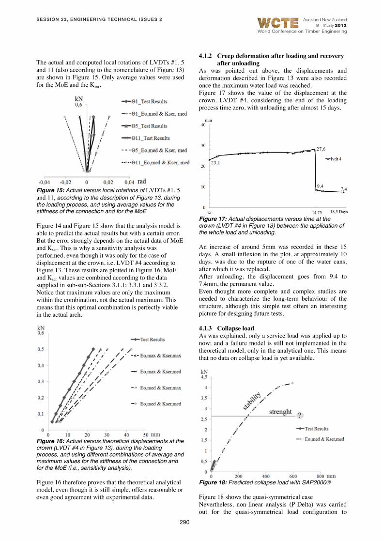
4.1.3 Collapse load As was explained, only a service load was applied up to now; and a failure model is still not implemented in the theoretical model, only in the analytical one. This means that no data on collapse load is yet available.
Figure 18: Predicted collapse load with SAP2000®
Figure 18 shows the quasi-symmetrical case Nevertheless, non-linear analysis (P-Delta) was carried out for the quasi-symmetrical load configuration to
SESSION 23, ENGINEERING TECHNICAL ISSUES 2

291
World Conference on Timber Engineering
Auckland New Zealand 15 - 19 July 2012
compute the collapse load due to general instability, (Figure 11a and Figure 12) using SAP2000®. The results are given in Figure 18. It shows that for this set-up general buckling would probably not be the failure mode, and local rupture is expected. But actual collapse loads will be available quite soon.
4.2 EIGEN FREQUENCIES The Eigen frequencies were measured and computed using SAP2000® for the unloaded arch, i.e. only considering the dead load. The results for the first four modes are presented in Table 1.
Table 1: Measured versus computed Eigen frequencies for the unloaded arch (just dead-load)
Frequency measured / computed (Hz) Mode 1st 3.9/2.7 Mode 2nd 7.2/5.4 Mode 3th 11.7/8.3 Mode 4th 19.9/11.4
As is the case for static load, the actual structure is stiffer than the theoretical model. The existing differences of around 40% are considered reasonable by the authors, as the model is still very simple; and it proves once again the consistency of the theoretical model. It must be kept in mind once again that the modal analysis developed to compute the Eigen frequencies does not consider the non-linear behaviour of NLINK #3. Further studies are being developed, including measuring with service loads in other cases.
5 CONCLUSIONS The article presented a first group of structural studies in order to model historical Latin-American laminated planked timber arches. After historical and construction work [1], structural study faced the static problem as a first step. A first FE analysis model has been presented, implemented in SAP2000®[7]. Even though it is still a simple model, modelling the planks with bars, it includes linear and non-linear springs, with 3D constraints, to simulate deformation in the connection system. P-delta non-linear analysis was performed. An experimental campaign was also performed, including a group of small-scale tests to characterize the connection systems, together with a full scale test of the arch, still with service loads. These tests form part of a more extensive program. Comparison between the experimental work and the proposed theoretical analytical model shows reasonable agreement, even though the model is only a simple first step. 2D and 3D FE models, with improvements in the constitutive equations, are now being developed by the same team [13]. The design model will also be addressed in further steps. The final stage will include the analysis and design of
the dynamic case; a necessary step for the strength assessment of this historical heritage. This analytical model has other many possible applications related with the timber composite construction. Another aim of this work is to use this analytical model to explore new structural types.
ACKNOWLEDGEMENTS
The authors would like to thank the work of research assistants at the Structural Department labs of the UPM, ETSA: Mr. Carlos Mendez, and, specially, Mr. Javier Rasines Sánchez.
REFERENCES
[1] Hurtado Valdez, Pedro A. Timber vaults: origin, evolution, geometry and construction between the XVII and XVIII century at the Viceroyalty of Peru. Ph. D. Thesis (in Spanish); ETS de Arquitectura, Madrid, UPM. Supervised by Enrique Nuere-Matauco and Jose L. Fernandez-Cabo. 2012
[2] Nuere Matauco, Enrique. The traditional Spanish carpentry. (in Spanish). Munilla–Lería, Madrid, 2000.
[3] Marzo, Anna. Analysis and refurbishment of traditional timber structure. (in Italian). Ph.D. Thesis. Napoles: Università degli Studi di Napoli Federico II, Facoltà di Ingegneria. 2006.
[4] De L’Orme, Philibert. Le premier tome de l’architecture de Philibert de L’Orme conseillier et aumosnier ordinaire du Roy & Abbé de S. Serge lez Angiers. Paris: Chez Federic Morel. 1567. (facs. Ed. Paris : Léonce Laget, Libraire-Èditeur, 1988).
[5] Hahnann, Lydia. 2006. How Stiff Is a Curved Timber Plank? Historical Discussions about Curved-Plank Structures. In: Proceedings of the 2nd International Congress on Construction History, vol.2, pp.1501-1516, Dunkeld, M. et al. (Ed). Queens´ College, Cambridge University, March 29-April 2, 2006.
[6] Meschke, Hans-Jürgen. 1989. Baukunst und –technik der hölzernen Wölbkonstruktionen – Vom Bogentragwek zum Stabnetzwerk-. Ph. D. Thesis. Aachen: Fakultät für Architektur der Rheinidch-Westfälischen Technischen Hochschule Aachen.
[7] SAP2000 v14.0.® Computer & Structures Inc. http://www.csiberkeley.com/ (accessed in April 14, 2010).
[8] Fernandez-Cabo, Jose L.; Fernandez-Lavandera, Jorge; Diez-Barra, Rafael; Avila-Jalvo, Jose. Timber Composite Beams with a Discrete Connection System. Accepted in May 2011 for its publication in Building and Structures, Institution of Civil Engineers, UK (reference of the manuscript: SB-D-11-00007).
[9] Kreuzinger, H. Mechanically Jointed Beams. Possibilities of Analysis and Some Special
SESSION 23, ENGINEERING TECHNICAL ISSUES 2

292
World Conference on Timber Engineering
Auckland New Zealand 15 - 19 July 2012
Problems. International Council for Research and Innovation in Building and Construction, CIB-W18. Venice, Italy. 2001.
[10] Kreuzinger, H. Verbundkonstruktionen. In: Holzbau Kalender 2002; pp. 598-621. J Ehlbeck (Edr.). Bruderverlag, Karlsruhe, 2001.
[11] Gliniorz, Kai-Uwe; Mosalam, Khalid M; Natterer Julius. 2002. Modeling of layered timber beams and ribbed shell frameworks. Composites: Part B 33, 367–381. 2002.
[12] Fernández-Golfín Seco, JI; Díez Barra, MR; Hermoso Prieto, E. Relaciones entre las variables clasificadoras de la madera estructural de los pinos silvestre y laricio de procedencia española. Materiales de Construcción, 53 (270): 45-55. 2003.
[13] Arce-Blanco, Marina. Analysis models of the vertically laminated timber arch (in Spanish). Ph. D. Thesis under development at UPM; supervised by Jose L. Fernandez-Cabo.
SESSION 23, ENGINEERING TECHNICAL ISSUES 2