Theconversion ofauranium plant tothe recovery ofzinc - · PDF fileTheconversion ofauranium...
9
The conversion of a uranium plant to the recovery of zinc by H. E. CROSS*. B.Sc. (Eng.)(Hons.) Rand (Fellow) SY NOPSIS The conversion of the Vogelstruisbult Uranium Plant into a plant for the produ~tion ~f ele~tr~lytic zinc is de- scribed. The reasons for the conversion, the prelimin~ry invest~gations. and ~h~ b~slc design prlnclpl~s are ~11out- lined, and a brief account is given of operating exp.e~lence.. during the commissioning of the plant, with equipment that had been put to a use for which it was not originally Intended. SAMEVATTING Die omskepping van die Vogelstruisbult-uraanaanleg in 'n aanleg vir ~ie pr~du ksie van elek~rol:tiese ~n~ wf~d beskr f. Die redes vir die omskepping, die voorlopige ondersoeke .en die baslese .ontwerpbeglns.e s. war a.ma In hooft~ekke aangegee en daar word 'n kort beskrywing gegee van d.le ~edryfservarln.g. tydens d.~ In~lensstelling van die aanleg. met uitrusting wat gebruik is vir doeleindes waarvoor dlt me oorspronklik ontwerp IS me. The Zinc Corporation of South Africa has been established with the principal objective of producing South Africa's requirements of virgin zinc metal as far as possible from local raw materials. A number of circumstances occurred in 1965 that combined to initiate the concept of establishing a local smelter as a replacement industry for a redund- ant uranium plant. These circum- stances were, in the main, as follows. (1) The over-riding principle that large domestic industries, such as the South African Iron and Steel Corporation (Iscor), which produces strategic products, should become as independent as possible of imported raw materials. Zinc metal was re- garded as a strategic material required by the steel and other industries, and at that time was a wholly imported product. At the same time, zinc concentrates were being produced in South Africa and South West Africa and were being exported for pro- cessing elsewhere. Iscor therefore examined the possibilities of establishing a zinc smelter, and approached Gold Fields about the availability of the South West Africa Company's concen- trates to augment the concen- trates that they intended to produce at the Rosh Pinah Mine in southern South West Africa. (2) The imminent closure of the uranium plant at Vogelstruisbult *Consulting Metallurgist, Gold Fields of South Africa, Limited. 140 NOVEMBER 1973 Gold Mining Areas. Vogelstruis- bult had not participated in the stretch-out agreements in respect of the uranium contracts and would be required to close down a comparatively new plant, which had been in commission for only ten years. The Chairman of the Company, Mr R. A. Hope, there- fore asked that the use of the plant or equipment for alterna- tive processes should be con- sidered. (3) Berg Aukas, the Gold Fields mine in South West Africa, produced zinc concentrates in addition to its principal output of lead-zinc vanadates. Two types of zinc concentrates were produced: con- ventional zinc blende and willem- ite, a zinc silicate. Tonnage- wise the willemite was the more important product, and exami- nation of the mine's ore reserves indicated that large tonnages could be produced for a con- siderable period of time. One problem, however, was the un- popularity of zinc silicates with conventional zinc smelters. The request was therefore made that consideration should be given to the establishment of a zinc- recovery plant in South Africa that would be able to treat zinc silicates in large quantities. Visits to producing zinc smelters drew attention to similarities be- tween an electrolytic-zinc smelter and a uranium plant, and a project was initiated that had as its specific objective the conversion of the Vogelstruisbult Uranium Plant to an electrolytic-zinc smelter based on local concentrates. ZINC TECHNOLOGY A conventional electrolytic-zinc plant purchases zinc sulphide con- centrates and processes them to produce zinc slab, according to the following basic technology. Concentrates are roasted to pro- duce sulphur dioxide and calcine, in which the zinc occurs as zinc oxide. The sulphur dioxide is converted to sulphuric acid. Calcine is leached in dilute sul- phuric acid under near-neutral con- ditions so that the zinc is dissolved but only a limited, though necessary, quantity of iron is taken into solution. The leach pulp is neutral. ized with excess calcine, thus pre- cipitating iron hydroxide, and is then thickened and filtered. Washing of the filter cake is necessary to reduce soluble zinc losses. The washed cake is discharged as residue. Solution purification is undertaken to prevent interference with effective electrolysis by substances that seriously hinder electroplating when present in concentrations as low as 0,01 mgfl. Essentially, purification consists in precipitation of impurities by activated zinc dust and is usually carried out in two stages: the first at about 90 °C, and the second at a lower temperature. Filtration for the removal of excess zinc dust and pre- cipitated sludge is carried out after each operation. Electrowinning of dissolved zinc is JOURNAL OF THE SOUTH AFRICAN INSTITUTE OF MINING AND METALLURGY
-
Upload
duongtuyen -
Category
Documents
-
view
218 -
download
1
Transcript of Theconversion ofauranium plant tothe recovery ofzinc - · PDF fileTheconversion ofauranium...
The conversion of a uranium plant to therecovery of zinc
by H. E. CROSS*. B.Sc. (Eng.)(Hons.) Rand (Fellow)
SY NOPSIS
The conversion of the Vogelstruisbult Uranium Plant into a plant for the produ~tion ~f ele~tr~lytic zinc is de-scribed. The reasons for the conversion, the prelimin~ry invest~gations. and ~h~ b~slc design prlnclpl~s are ~11out-lined, and a brief account is given of operating exp.e~lence.. during the commissioning of the plant, with equipmentthat had been put to a use for which it was not originally Intended.
SAMEVATTING
Die omskepping van die Vogelstruisbult-uraanaanleg in 'n aanleg vir ~ie pr~du ksie van elek~rol:tiese~n~ wf~d
beskr f. Die redes vir die omskepping, die voorlopige ondersoeke .en die baslese .ontwerpbeglns.e s. war a.ma Inhooft~ekke aangegee en daar word 'n kort beskrywing gegee van d.le ~edryfservarln.g. tydens d.~ In~lensstelling vandie aanleg. met uitrusting wat gebruik is vir doeleindes waarvoor dlt me oorspronklik ontwerp ISme.
The Zinc Corporation of SouthAfrica has been established with theprincipal objective of producingSouth Africa's requirements of virginzinc metal as far as possible fromlocal raw materials. A number ofcircumstances occurred in 1965 thatcombined to initiate the concept ofestablishing a local smelter as areplacement industry for a redund-ant uranium plant. These circum-stances were, in the main, as follows.(1) The over-riding principle that
large domestic industries, suchas the South African Iron andSteel Corporation (Iscor), whichproduces strategic products,should become as independent aspossible of imported rawmaterials. Zinc metal was re-garded as a strategic materialrequired by the steel and otherindustries, and at that time was awholly imported product. At thesame time, zinc concentrateswere being produced in SouthAfrica and South West Africaand were being exported for pro-cessing elsewhere. Iscor thereforeexamined the possibilities ofestablishing a zinc smelter, andapproached Gold Fields aboutthe availability of the SouthWest Africa Company's concen-trates to augment the concen-trates that they intended toproduce at the Rosh Pinah Minein southern South West Africa.
(2) The imminent closure of theuranium plant at Vogelstruisbult
*Consulting Metallurgist, Gold Fields ofSouth Africa, Limited.
140 NOVEMBER 1973
Gold Mining Areas. Vogelstruis-bult had not participated in thestretch-out agreements in respectof the uranium contracts andwould be required to close down acomparatively new plant, whichhad been in commission for onlyten years. The Chairman of theCompany, Mr R. A. Hope, there-fore asked that the use of theplant or equipment for alterna-tive processes should be con-sidered.
(3) Berg Aukas, the Gold Fields minein South West Africa, producedzinc concentrates in addition toits principal output of lead-zincvanadates. Two types of zincconcentrates were produced: con-ventional zinc blende and willem-ite, a zinc silicate. Tonnage-wise the willemite was the moreimportant product, and exami-nation of the mine's ore reservesindicated that large tonnagescould be produced for a con-siderable period of time. Oneproblem, however, was the un-popularity of zinc silicates withconventional zinc smelters. Therequest was therefore made thatconsideration should be given tothe establishment of a zinc-recovery plant in South Africathat would be able to treat zincsilicates in large quantities.
Visits to producing zinc smeltersdrew attention to similarities be-tween an electrolytic-zinc smelterand a uranium plant, and a projectwas initiated that had as its specificobjective the conversion of the
Vogelstruisbult Uranium Plant to anelectrolytic-zinc smelter based onlocal concentrates.
ZINC TECHNOLOGY
A conventional electrolytic-zincplant purchases zinc sulphide con-centrates and processes them toproduce zinc slab, according to thefollowing basic technology.
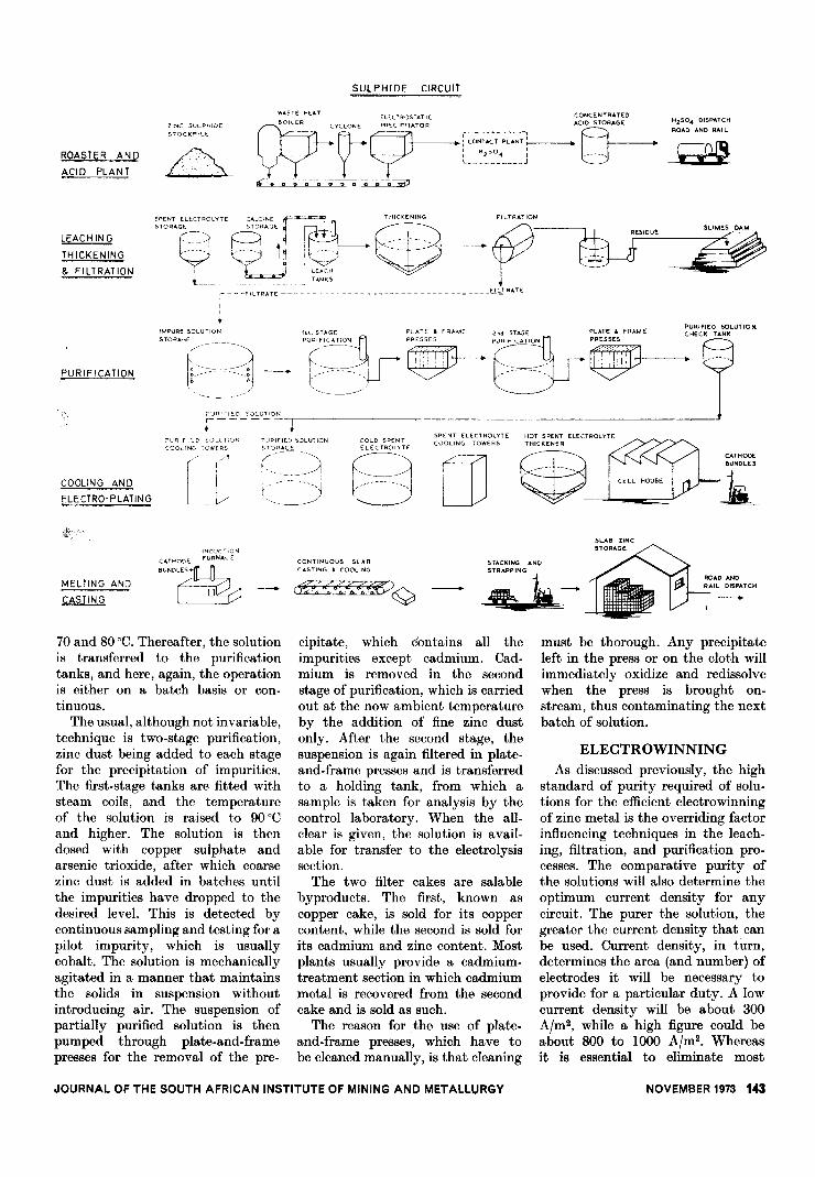
Concentrates are roasted to pro-duce sulphur dioxide and calcine, inwhich the zinc occurs as zinc oxide.The sulphur dioxide is converted tosulphuric acid.
Calcine is leached in dilute sul-phuric acid under near-neutral con-ditions so that the zinc is dissolvedbut only a limited, though necessary,quantity of iron is taken intosolution. The leach pulp is neutral.ized with excess calcine, thus pre-cipitating iron hydroxide, and is thenthickened and filtered. Washing ofthe filter cake is necessary to reducesoluble zinc losses. The washed cakeis discharged as residue.
Solution purification is undertakento prevent interference with effectiveelectrolysis by substances thatseriously hinder electroplating whenpresent in concentrations as low as0,01 mgfl. Essentially, purificationconsists in precipitation of impuritiesby activated zinc dust and is usuallycarried out in two stages: the firstat about 90 °C, and the second at alower temperature. Filtration for theremoval of excess zinc dust and pre-cipitated sludge is carried out aftereach operation.
Electrowinning of dissolved zinc is
JOURNAL OF THE SOUTH AFRICAN INSTITUTE OF MINING AND METALLURGY
the final process in the chemicalsequence, and is normally carriedout in lead-lined concrete cells,using lead anodes and aluminiumcathodes. An emf of 3t V is appliedacross electrodes, and current densi-ties vary from about 300 to 800 Afm2.Under these conditions, considerableheat is developed in the solution,and it is necessary to provide coolingtowers in the circuit. The electro-plating of the zinc results in re-generation of sulphuric acid, andspent electrolyte is recycled to theleaching section for the dissolutionof calcine, thus completely closingthe chemical circuit. Zinc-metalsheets are stripped from thecathodes.
Melting of cathodes into salableingots is the final operation prior tomarketing.
This brief description will help toshow the similarities between therecovery of dissolved uranium byacid leaching and the electrolyticrecovery of zinc. It will also helpto explain the thinking behind theconcept to convert the redundanturanium plant to the recovery ofzinc.
Once the stage of a completefeasibility report had been reached,it became necessary to examine allthe relevant factors more closely. Inbroad outline, these could be classi-fied into two major groups: technicalfeasibility and economic feasibility.This paper deals principally with thetechnical considerations.
FEED STOCK
Basically, the project was investi-gated on the assumption that theraw feed to the plant would consistof the following.(a) Zinc blende concentrates from
Iscor's Rosh Pinah Mine inSouth West Africa, of which aprobable analysis (in percentages)would be Zn 53, S 27, Fe 2,5, andCd 0,08, with the followingdeleterious constituents: Ca 1,5,and Mg 0,75.
(b) Willemite concentrate from BergAukas, the Gold Fields mine inSouth West Africa. Typical sig-nificant constituents (in per-centages) would probably be Zn47, Si02 25, Ca 0,80, Mg 0,54,and Ge 0,009.
Of these two raw materials, the
sulphide concentrate is typical ofclean zinc concentrates that aretreated successfully elsewhere andpresented no foreseeable problems.The willemite concentrate, on theother hand, was known to be un-acceptable to electrolytic plantsowing to the solubility of the silica insulphuric acid, which results in theproduction of a difficult-to-filter,voluminous gelatinous precipitate.
However, a programme of labora-tory investigations was instituted,and possible techniques for thetreatment of this material wereestablished. These were confirmed onboth laboratory and pilot-plantscales at the East St. Louis works ofthe American Zinc Company, andwere later confirmed on a pilot-plantscale by Zincor. The translation ofthese results into a production pro-cess was never pursued because theBerg Aukas Mine indicated that ithad decided to market its non-sulphidic zinc in the form of Waelzoxide. Samples of oxide producedon its behalf in a pilot plant inGermany were made available fortesting, and extraction tests on thismaterial had the following approxi-mate analysis (in percentages): Zn63, Pb ll, Si02 1,0, Ca 1,0, Mg 0,5,and Ge 0,002. The fluorine contentwas 265 p.p.m.
At that stage it was decided toerect a pilot plant at Vogelstruisbultfor larger-than-laboratory scale in-vestigations of the recoverability ofzinc from Rosh Pinah concentratesand Waelz oxide.
PILOT PLANT
The pilot-plant units were chosento enable charges of 1l0 kg of calcineor Waelz oxide to be treated. Theplant consisted of a rubber-linedconical leaching tank, mechanicallystirred and provided with lead coilsfor steam heating. This was followedby a stainless-steel rotary-drum filterand two purification tanks. A plate-and-frame filter was provided forpurification. Finally, storage tanksfor purified solution and two electro-lysis cells, each containing two pro-duction-size anodes and one cathode,were provided.
It was possible either to runsingle-batch tests with this equip-ment, or to recycle spent electrolyteand thus simulate continuous oper-
JOURNAL OF THE SOUTH AFRICAN INSTITUTE OF MINING AND METALLURGY
ation by the repetition of cycles asoften as required. Twenty-five cycleswere considered sufficient to simulatecontinuous closed-circuit operations.
For the roasting of sulphide con-centrates, a multiple-hearth type ofroaster was available, which, al-though not ideal, produced calcinesufficiently well roasted to givemeaningful results.
DISCUSSION OF ZINC TECH-NOLOGY
The simple sequence of operationspreviously enumerated appears tobe straight forward. In practice,however, the unit operations arefar more complex, and a morethorough understanding is necessaryto appreciate the complexities ofoperating plants. Essentially, theobjective is to dissolve the zinccontent of the feed materials and toelectrowin the zinc as pure metal.
For a proper understanding ofthe processes involved, it is advisableto examine the electrolysis operationin the first instance. The preferredelectrolyte is a zinc sulphate solutionin which are located lead anodes andaluminium cathodes, with an im-posed emf of 3t V. Under normalcircumstances, this emf will causewater to dissociate, as well as plateout zinc. However, with very pureelectrolyte, a hydrogen over. voltageis set up and zinc is plated out inpreference to hydrogen. This fortu-nate mechanism makes it possible toachieve a current utilization for theplating out of zinc of as high as92 per cent. However, if impuritiesare present, even in the most minuteconcentrations, they reduce thehydrogen over-voltage, and currentis wasted on the electrolysis ofwater.
A further factor to be allowed foris that the successful use of alu-minium cathodes depends on thenatural passivity at the surface ofaluminium, which prevents adhesionof deposited zinc to the aluminiumand permits ready stripping of thedeposited sheet. If, however, thispassive oxide film is removed, thezinc becomes firmly welded to thealuminium and cannot be stripped.One of the worst offenders here isfluorine, which causes sticking whenpresent in concentrations of as low as20 p.p.m. As is well known, fluorine
NOVEMBER1973 141
cannot readily be precipitated fromsulphate solutions, and itis a trouble-maker in most zincplants. Yet another impurity that isusually avoided is magnesium, which,too, cannot readily be precipitatedfrom sulphate solutions and whenpresent builds up to undesirableconcentrations in a cyclic operation.It has a twofold effect. In the firstplace, it displaces zinc in saturatedsolution. With an atomic weight of24, compared with 65 for zinc, 1 g ofmagnesium in solution will displace2,7 g of zinc. Secondly, the presenceof magnesium increases the viscosityof the solution, which has the effectof decreasing current efficiency andof increasing voltage drop. Theremoval of impurities from zincsulphate solution thus becomes theoverriding consideration in planttechnology.
With this general background, amore detailed discussion of theimplications of the unit processfollows.
ROASTING
This is an area to which majoreffort is directed. The primaryobjective is to produce acid-solublezinc oxide and sulphur dioxide byroasting at a bout 930 QC. There are,however, some side reactions thataffect the subsequent leaching pro-cess. Most sulphide ores contain ironminerals and some base-metal miner-als that participate in the roastingreactions. Some iron minerals un-fortunately react with zinc and basemetals to form ferrites, which areinsoluble in leach liquor. The form-ation of ferrites can be reducedby roasting at a lower temperature,but under this condition a largeproportion of the sulphur burns offas sulphur trioxide, and either per-sists as a gas or reacts with basemetals to form sulphates. On theface of it, this should be ad.vantageous in that the load on thesulphuric acid plant will be reduced.However, this is not the case be-cause, in the cyclic zinc-leachingand electrowinning operation, theprocess per se is not a net consumerof acid, and zinc sulphate intro-duced into the circuit can result in abuild-up of acid that would have tobe bled from the circuit unless thereare sufficient acid-consuming con-
142 NOVEMBER 1973
stituents in the calcine to forminsoluble precipitates and to be re-moved as such. Two such con-stituents are lead and calcium.
Roasting therefore calls for ameasure of tight control, and boththe design of the roasters and theoperating parameters play an im-portant role in the achievement ofmaximum efficiency.
HOT -GAS TREATMENT
The calcine leaves the roastersat about 900 QC, and, in the case offluidized- bed reactors, a portion ofthe calcine is discharged as coarsematerial via a bed-overflow weir,while the remainder is entrained inthe sulphur dioxide-bearing gases,from which it has to be separatedand cooled. The solution-purificationprocess uses a large quantity ofsteam, and it has become commonpractice to provide waste-heat boilersthat serve the dual purpose ofcooling the gases with their entrainedsolids and of providing the steamrequired on the plant. Rapid coolingof the gases has the beneficial effectof reducing the autogenous oxidationof sulphur dioxide to sulphur tri-oxide. A problem with boilers is theaccumulation of dust on the tubebundles, and highly efficient rappinggear must be provided. The qualityof the calcine, too, can affect thenature of the dust deposit, andcopper and lead in the concentratescan be harmful, particularly if theyoccur together. In fact, these twometals also exercise a deleteriousinfluence in the roasters and cancause freezing of the bed at highoperating temperatures.
Some of the gas-borne solids arerecovered from the boilers, and theremainder are removed by cyclonesand hot-gas electrostatic precipi-tators before they enter the usualtrain of vessels in a contact sul-phuric acid plant. The solids col-lected from the bed overflow, boilerhopper, cyclones, and electrostaticprecipitator are further cooled andde-nodulized in a dry ball millprior to being stored dry ahead ofleaching.
LEACHING
The object ofleaching is to dissolvethe zinc oxide into a near-saturatedsolution of zinc sulphate, without
dissolving other soluble constituentsof the calcine. The most soluble ofthese constituents is the iron oxide,which, on neutralizing, forms theusual voluminous, difficult-ta-filter,ferric hydroxide. However, somedissolved iron is desirable for thefollowing reason. Whereas the majorremoval of impurities is achieved byprecipitation with zinc dust, it isdifficult to remove all impurities bythis technique. Such impurities can,however, be controlled by adsorptiononto ferric hydroxide precipitate,which is discharged as leach residue.
One of two leaching procedures isnormally practised: batch leachingor continuous leaching.
In batch leaching, an accuratelymeasured quantity of cell acid isintroduced into the agitator, fol-lowed by a charge of calcine, ac-curately weighed to represent thestoichiometric quantity of zinc to bedissolved. The calcine is introducedas rapidly as possible into the acid,and the free-acid strength fallsquickly to a level at which theattack on iron minerals is minim-ized. Agitation is continued untilthe readily available zinc has beendissolved and the pulp is just basic.The desired degree of basicity isachieved by fine additions of eitheracid or calcine.
In continuous leaching, dissolu-tion takes place in a train of agi-tators. Into the first of these agi-tators, continuous additions of bothacid and calcine are made in thecorrect proportion to enable com-plete dissolution of the zinc to takeplace while at the same time endingup with the desired basicity. By thismeans the dissolution of iron ismaintained at the desired level.
Liquid-solids separation of theleached pulp finally takes place in acombination of thickeners and filters,which range from the pressure leafbatch type to continuous drummachines.
PURIFICATION
Although neither filtrate northickener overflow is normally aclear solution, it is unusual to pro-vide clarifiers ahead of purification.The usual procedure is to storeimpure solution in tanks fitted withsteam coils in which the solutiontemperature is raised to between
JOURNAL OF THE SOUTH AFRICAN INSTITUTE OF MINING AND METALLURGY
"NC SULPHIDE
STOCKPILE
ROASTER AND
ACID PLAN T/A
SULPHIDE CIRCUIT
CONCENTRATEDACID STORAGE
~u-- hO$
WASTE HEAT'LECTROSTATIC
WBOILER
CYCLONE PRECIPITATOR
YY - r~~N~~~;;::N-T:
: H2S0. :L J
~~-;-~~~
H2S0. DISPATCH
ROAD ANDR"
L
LEACH IN G
THICKENING
& FILTRATION
;~;~TA:ELEmo
.
LYTE;~~~~~E
~
.
" r;:t~ C~~ """'O-
8 e ~
It;?.
~ M--~ ~~-_:t_J
~~~~~'
.. r~ -- -FlURHE -- -
u-- -- -
u u- u- --
_u- u- uuU"RATE
PURIFICATION
IMPURE SOLUTIONSTORAGE
~ni. .~--- -
PU"'IED SOLUTION
r-----,PuR'FlED SOLL,T,I'"(OOLlN(, TOWE'S
COOLING AND
ELECTRa-PLATING
MEL TlNG AND
~
INDUCTIONFURNACE
;~:~
70 and 80 QC.Thereafter, the solution
is transferred to the purificationtanks, and here, again, the operationis either on a batch basis or con-tinuous.
The usual, although not invariable,technique is two-stage purification,zinc dust being added to each stagefor the precipitation of impurities.The first-stage tanks are fitted withsteam coils, and the temperatureof the solution is raised to 90 aCand higher. The solution is thendosed with copper sulphate andarsenic trioxide, after which coarsezinc dust is added in batches untilthe impurities have dropped to thedesired level. This is detected bycontinuous sampling and testing for apilot impurity, which is usuallycobalt. The solution is mechanicallyagitated in a manner that maintainsthe solids in suspension withoutintroducing air. The suspension ofpartially purified solution is thenpumped through plate-and-framepresses for the removal of the pre-
'"STAGE PLATE' FRAME 20' STAGE
P?~~~]
.r I~ . PUR'~C~~'O~~
l ~,
/'
;~~,',,\'-"' ;:~1""O'~~.-_.-..
PUPIFlED >CLUTlON
(jR;:~f/ ---')'-,, '
SPENT ELECTROLYTE HOT SPENT ELECTROLYTECOLD SPENT COOLING TOWERS THICKENER
8[]~ 1L
CONTINUOUS SLABCASTING. COOLING
CATHODEBUNDLES
(~,,; .«~.( «(9~
STACKING AND
~ -=--
cipitate, which contains all theimpurities except cadmium. Cad-mium is removed in the secondstage of purification, which is carriedout at the now ambient temperatureby the addition of fine zinc dustonly. After the second stage, thesuspension is again filtered in plate-and-frame presses and is transferredto a holding tank, from which asample is taken for analysis by thecontrol laboratory. When the all-clear is given, the solution is avail-able for transfer to the electrolysissection.
The two filter cakes are salablebyproducts. The first, known ascopper cake, is sold for its coppercontent, while the second is sold forits cadmium and zinc content. Mostplants usually provide a cadmium-treatment section in which cadmiummetal is recovered from the secondcake and is sold as such.
The reason for the use of plate-and-frame presses, which have tobe cleaned manually, is that cleaning
JOURNAL OF THE SOUTH AFRICAN INSTITUTE OF MINING AND METALLURGY
must be thorough. Any precipitateleft in the press or on the cloth willimmediately oxidize and redissolvewhen the press is brought on-stream, thus contaminating the nextbatch of solution.
ELECTROWINNING
As discussed previously, the highstandard of purity required of solu-tions for the efficient electrowinningof zinc metal is the overriding factorinfluencing techniques in the leach-ing, filtration, and purification pro-cesses. The comparative purity ofthe solutions will also determine theoptimum current density for anycircuit. The purer the solution, thegreater the current density that canbe used. Current density, in turn,determines the area (and number) ofelectrodes it will be necessary toprovide for a particular duty. A lowcurrent density will be about 300Ajm2, while a high figure could beabout 800 to 1000 Ajm2. Whereasit is essential to eliminate most
NOVEMBER1973 143
metals from the cell acid, iron canbe tolerated to a limited extent, anda limited amount of manganese isactually a necessary constituent ofthe electrolyte. Iron finds its wayinto the solution via the suspendedsolids present in the impure filtrateand thickener overflow, and is re-dissolved in the purification cycle.Manganese is deliberately added tothe leach circuit as manganesedioxide and is not removed by zincpurification. The electrolyte in ahealthy cell circuit is given a deepwine colour by manganese, whichhas a twofold effect: to assistelectrodeposition of the zinc, and todeposit as a manganese dioxidescale on the anodes and a heavysludge in the bottom of the cell.This necessitates a regular pro-gramme of anode cleaning andsludge removal. This sludge is usuallyreturned to the leaching circuit,where the manganese is redissolvedand participates in yet anotherclosed cycle.
As previously mentioned, theanodes consist of lead sheets thatare usually perforated to assist thecirculation of electrolyte. Theseanodes are cast from lead alloyedwith a small percentage of silver(1 per cent or less) and have cast-incopper header bars. The cathodes,on the other hand, are usuallyfabricated from aluminium sheetand are welded to cast aluminium-alloy header bars fitted with coppercontacts.
Zinc is deposited into the cathodeas a smooth sheet, which is allowedto reach a thickness of 4 to 6 mmbefore being stripped. Adhesion tothe cathode is firm, but the sheet canreadily be removed by loosening acorner and prising it free. Thelengths of plating-stripping cycleswill depend on the current densityemployed, and usually last from16 to 48 hours, 24 hours beingcommon. Stripping is assisted byprevention of the growth of zincround the vertical edges of thecathode sheets. This can be done bycovering these edges with rubber,plastic, or wooden edge-strips.
MEL TING
The stripped cathode sheets areaccumulated and melted in furnaces,which in the older plants are fired by
144 NOVEMBER 1973
gas or oil. In the new plants, in-duction furnaces are used and themolten metal is cast into suitablysized ingots or slabs in mechanicalcasting machines.
The usual grade of electrolyticzinc metal is Zn 2 with a zinc purityof 99,95 per cent or higher. The useof modifying agents in the cellcircuit makes it possible to produceZn 1, or special high-grade (SHG),which assays more than 99,995 percent zinc.
MATERIALS OFCONSTRUCTION
The range of materials that can beused for the construction of equip-ment in an electrolytic-zinc plant islimited. Almost all items of equip-ment that are in contact withsoluti0ns or pulps must be capable ofwithstanding attack by hot, dilutesulphuric acid and saturated zincsulphate solutions. In the cell house,it is essential that non-conductivematerials are employed to preventcurrent leakage and to safeguard theoperators.
In many of the older plants,wooden vats are used in the leachingand purification sections, and thecooling towers, too, are made oftimber. Electrowinning cells areusually cast out of concrete andlined with lead, while wood is usedextensively for the launders.
A factor that has continually to beborne in mind in the design of aplant is that many of the solutionsare saturated, not only with zincplus magnesium sulphate, but alsowith calcium sulphate, and that thescaling of gypsum becomes a realproblem and calls for frequent clean-ing of pipes, cooling towers, andother items of equipment.
Modern zinc plants make extensiveuse of stainless steel, fibre glass,and other modern industrial plastics.Care must be taken to preventelectrolytic corrosion of stainlesssteel when it is used for equipmentin the purification and electrolyticsections. Any impurities, such asnickel, that might enter the circuitsolutions as a result of stainless-steel corrosion could cause havocin the cell house.
FLOW CIRCUITS
The pilot-plant results showedthat the use of conventional circuits
would result in good recoveries fromthe concentrates tested. However,one problem emerged; namely, thatthe Waelz oxide tested containedsufficient fluorine to give rise toserious doubts about whether cath-ode zinc would stick on the alu-minium plates. It therefore becamenecessary to make provision, eitherto eliminate the fluorine from theWaelz oxide by installing a second-stage densifying kiln, or to deal withthe fluorine in the Zincor plant.It was eventually decided to dealwith the problem at Zincor in thefollowing manner. Two completelyseparate circuits would be provided,one to treat low-fluorine concen-trates and the other to handle high-fluorine oxides. In the cell house,provision would be made, first, toplate the cathodes in the fluorine-free solution and, when a thicklayer of zinc had been deposited onthe aluminium cathode, to transferthe latter to the high-fluorine circuitfor plating to be completed on thezinc base. It was argued that thefluorine present in the solutionused for the second stage of electrodeposition would not cause the initiallayer of zinc to stick to the alu-minium sheet. This argument has, inpractice, been found to be correct.
A strange feature of the pilot-plant testwork was that stickingnever took place, even with solutionshaving as high a concentrationof fluorine as 300 p.p.m. Only whenthese solutions were artificiallyspiked to raise the concentration to1000 p.p.m. could sticking be in-duced.
DECISION TO PROCEEDWITH CONVERSION
After the conclusion of the pilotplant testwork, a technical andfinancial feasibility report was issued(February, 1967), and this wasfollowed by the decision to proceedwith the formation of the Companyand with the conversion of the re-dundant uranium plant to an electro-lytic-zinc smelter.
In broad outline, it was agreedthat action should proceed accordingto the following general principles.
The new Company would applyto the Departments of Planning,Commerce, and Bantu Administra-tion for the necessary permission to
JOURNAL OF THE SOUTH AFRICAN INSTITUTE OF MINING AND METALLURGY
eI'ect a zinc plant at Vogelstruisbulton the basis (a) that this was to be areplacement industry for a dyingmine, and (b) that it would be astrategic industry providing thecountry's requirements of a pre-viously imported commodity.
.
The principa. advaQtages of theconversIon were as follows:(a) services l1uch as :power, road and
r&H access, w&ter, housing, ac-commodation for Bantu, and anear-by labour force were avail-able;
(b) Vogelstruisbult was within a75-mile radius of over 90 per centof the inland consumers of zinc;and
(c) items of plant equipment andbuildings were available for con-version to use in the new plant.
The main disadvantages were thatthe items of equipment referred towere not of the type normallyemployed in zinc plants, and that alayout taking full advantage of theequipment and building would re-sult in a somewhat unsatisfactoryflow path of materials.
However, the advantages ap-peared to heavily outweigh thedisadvantages, and a Consultantwas engaged to assist with theplanning of the conversion.
BASIC DESIGN PRINCIPLES
The following broad principleswere to be used as the basis for thedesign of the new plant.(1) Initially, the daily capacity
would be 100 tons of slab zincof electrolytic grade.
(2) There would be two completelyparallel plants, each with acapacity of 50 tons of slabs perday. One circuit would treathigh-fluorine material (Waelz ox-ide), and the other would treatmaterial low in fluorine (sul-phides). Sticking of cathodesheets in the oxide circuit wouldbe prevented by pre-plating ofcathodes in the calcine (sulphide)cells.
ROASTING AND ACIDPRODUCTION
The new roasting plant wouldemploy the most efficient fluidized-bed roasters for zinc concentrates,and would be required to produce amaximum of 0,30 per cent sulphide
sulphur in the calcine with, at thesame time, a minimum of sulphateproduction. The plant would in-corporate waste-heat boilers and notelectrostatic precipitators. It wouldbe followed by a contact acid plantaQd wou.d make use of the latestdoub.e-&bsorption techniques to en-sure maximum conversion of sulphurdioxide to sul:phur trioxide (morethan 99,5 per cent conversion).When the contract for the roastingand acid plant was eventually issued,an acid capacity of 170 tons perday of monohydrate was stipulatedand two roasters were specified,each to be capable of roastingsufficient concentrate to produce85 tons of acid per day (equivalentto a capacity of more than 50 tonsof slab zinc each per day). Initially,one roaster was to be used to burnzinc blende, while the other wouldstart up on pyrite but would berequired to switch over to blende atsome future date. The latter re-quirement presented interestingproblems, as the usual zinc con-centrate contains about 30 per cent.sulphur, compared with 40 per centand more in pyrite. The flexibilitywas eventually achieved by theprovision of removable cooling coilsin the bed of the pyrite roaster.
It was anticipated that the pyriterequired for the second roasterwould be massive ore from a mineto be opened up in the NorthernCape and that it would be necessaryto make provision to mill the ore atZincor.
RAW -MA TERIALSHANDLING
Concentrate would be delivered byrail, and the final zinc and acidproduced would leave the propertyby either rail or road.
There was a rail spur to the plantsite, but it needed to be doubledand rerouted to a certain extent.In addition, the siding at Struisbultwould have to be redesigned and re-built, in collaboration with therailway administration.
The existing all-concrete gold-plant mill building, which hadpreviously housed four milling units(each consisting of one 9 ft by 10 ftball mill and two 6 ft 6 in by 20 ftpebble mills), was to be cleared andused for the storage of concentrates.
JOURNAL OF THE SOUTH AFRICAN INSTITUTE OF MINING AND METALLURGY
The existing mill ore.feed binswere to remain intact to receivepyrite ore, and one 9 ft by 10 ftball mill was to be retained inposition for the dry-grinding ofm&f!sive pyrite ore.
A suitable arrangement of con.veyor belts would be provided tofeed concentrate from the store tothe roasters.
C&lcine and Wl\,elz oxide were tobe stored in available pachucl\,agitators (33 ft in diameter and 48 ftin height), two for calcine and fourfor Waelz oxide. Only one of thecalcine tanks (previously a uranium-pulp stock tank) was correctly sited.The remaining five were gold-plantagitators that would have to bemoved to new positions. Provisionwas made to cool and dry-mill thecalcine and then to transfer itpneumatically in a continuous pres-sure system to the stock tanks.The mill earmarked for this purposewas to be transferred from themanganese-preparation section to aposition adjoining the roasters. Fur-ther handling of the calcine fromstock tanks to agitators was to beeffected by bucket elevators andscrew feeders via weigher-feeders.
The handling system for Waelzoxide was designed to incorporatea receiving bin below the rail track,followed by a series of screw feedersand bucket elevators.
LEACHING SECTION
Batch leaching would be practisedin four existing rubber-lined pachucatanks (22 ft 6 in by 45 ft high), twobeing required for the leaching ofcalcine and two for the leaching ofoxide. In addition, two existingsimilar tanks, which adjoined theagitators, would be used for storingrecycled spent electrolyte requiredfor leaching, and one further existingagitator was to be used as a surgetank for Waelz oxide between thetrue storage tanks and the agitators.
The existing manganese and lime-stone preparation section, whichconsisted of two 25 ft by 12 ftthickeners, was to be acid-proofedby the addition of a rubber lining,and augmented by two existing10 ft by 10 ft acid-proofed agitatorsand one 15 ft by 10 ft acid-proofeddissolving tank for the preparationand feeding of manganese dioxide
NOVEMBER1973 145
sludge to the leaching tanks.The leaching of calcine called for
the partial filling of leaching tankswith spent cell acid, followed by thesimultaneous rapid transfer of cal-cine and the remaining quantity ofcell acid in measured quantitiesdesigned so that the leaching cyclefinished with neutral or slightlybasic pulp. It was planned to controlthe dissolution of iron in this way.Waelz oxide, being free from ironand having been received as apelletized material, would undergo asomewhat different leaching pro-cedure. Pellets and cell acid wouldbe fed simultaneously into a scrubber(mounted above the leaching tanks),in which disintegration of the pelletswould occur and from which thepulp would flow into the agitators.
SOLIDS-LIQUIDSEPARATION
The flow in this section was to becountercurrent separation, utilizingtwo thickeners and two filters inseries for each of the two circuits.Use was to be made of three existingconcrete thickeners and one existingtank, which it would be necessary toconvert to a thickener. Four of theexisting ten acid-proofed rotary fil-ters were to be recommissioned.
Two remaining 50 ft diametertanks would be acid-proofed andfitted with steam-heating coils forstorage of filtrate prior to purifi-cation. All thickeners and storagetanks would require acid-proofing.
The filter building would be re-tained, and the portion previouslyoccupied by non-acid filters wouldbe cleared and used as a plantworkshop.
Compressors and vacuum pumpswere to be recommissioned.
PURIFICATION SECTION
This section was designed toincorporate pressure clarification fol-lowed by batch purification in twostages, the first at temperatures inexcess of 90 °C and the second atambient solution temperature. Pres-sure filtration in plate-and-framefilters would take place after eachpurification.
The building that had housed theion-exchange cum precipitation plantwas to house the purification section,
146 NOVEMBER 1973
and three existing eluate- andeffiuent-storage tanks, 30 ft indiameter by 12 ft in height, wereto form the nucleus of the purifi-cation tanks. Eight tanks in allwould be required, four in eachcircuit, of which two would befirst-stage tanks and two second-stage tanks. The first-stage tankswould be heated with steam coils,and would be lead-lined and laggedwith insulation against heat losses.The unheated second-stage tankswould be rubber-lined. All tankswould be fitted with agitator mech-anisms capable of imparting satis-factory agitation without effectingaeration. It was necessary to clearthe building and to erect an elevated,acid-proofed working floor. In ad-dition, the building required ex-tending in order to accommodatetwo pressure leaf clarifiers, fourthirty-plate 30 in by 30 in pressurefilters, a control cabinet, and theeight 30 ft diameter tanks. Theclarifiers consisted of two 60 indiameter horizontal stainless-steelpressure filters, each containingtwenty 41 in by 44 in canvas-coveredfilter leaves. Steam for heating theimpure-filtrate storages and the first-stage purification tanks was to bederived from the waste-heat boilersin the roaster plant.
In addition to the basic equipmentmentioned under this section, pro-vision had to be made for adequateventing of the purification tanks andsafe discharge of the gases producedduring purification, the most danger-ous of which could be arsene. Pro-vision had also to be made for zincdust (coarse for first-stage purifi-cation and finer for second-stage)to be stored at each purificationtank and added in accurately mea-sured quantities by means of weigh-feeders.
Provision was also to be madefor a conveniently placed inform-ation centre and control room onthe operating floor.
Before purified solution is trans-ferred to the cell house, it is necessaryto give it a final check for purity,and for this purpose two holdingtanks would have to be provided.Existing 15 ft by 45 ft pachucatanks were to be acid-proofed andresited for this purpose.
CELL HOUSE
The building that had housed theflotation plant attached to theuranium plant was set aside for useas the new cell house.
It was badly placed geographic-ally, and the moderately hot satu-rated solution would have to betransferred across the area occupiedby the thickeners, the filtrationbuilding, the leaching plant, theacid plant, and the cell house itself,to the tanks that would be providedas storage for purified solution. Onthe other hand, it was convenientlysituated for future extensions, forthe erection of peripheral equip-ment, and for the shipping of slabzinc by rail. It would be necessaryto clear the building completely,to demolish the existing raisedfloors and erect a new working floorat the correct level, to move certainpillars, and to open up the roof toprovide for free ventilation. In ad-dition, the brick-panelled walls wouldhave to be replaced by ventilationlouvres at ground level to providefor through-draught. The cell housewas designed to incorporate twocompletely separate circuits. Thebasic units decided on were asfollows: aluminium cathodes madeup of 3/16 in plate welded to alu-minium header bars, the submergedsurface measuring 20 in by 30 in;lead cathodes, 5/16 in thick and castin lead alloyed with 0,75 per centsilver, the lead to be cast roundcopper header bars and the sub-merged area to measure 19t in by28 in, and to be perforated with 1 indiameter holes spaced at 3 in centres;individual cells to be cast in concreteand lined with lead and to accom-modate 40 cathodes and 41 anodes,the cells to be arranged side by sidein rows of twelve cells per row andeach circuit to be provided with tenrows of cells. Thus, each circuitwould consist of a total of 120 cellscontaining 4800 cathodes, and theplating area in each cell would be332 ft2 and the total plating areaper circuit would be 39840 ft2.
The electric circuit provided forparallel flow across each cell,with cells and banks in series. Thus,the voltage drop across each cellwould be 3* V and across the entirecircuit 420 V. The current densitywould be about 70 A/ft2, and pro-
JOURNAL OF THE SOUTH AFRICAN INSTITUTE OF MINING AND METALLURGY
vision would have to be made for atotal load of 23 240 A per circuit.When the orders were finally placed,they were for two rectiformers, eachwith a capacity of 27 000 A and680V.
It was decided that all launders inthe cell house should be of resin-impregnated fibre glass.
COOLING TOWERS ANDELECTROLYTE STORAGE
In the layout of the solutioncircuit, it was decided that thepurified solution should be cooled,after it had been piped to the cell-house area, in three evaporativecooling towers, and that the solutionshould be pumped from the holdingtanks at the purification section tothose cooling towers. The coldsolution, prior to joining the cellcircuit, would then be stored in tworubber-lined steel tanks 50 ft indiameter by 8 ft.
To achieve a high flowrate ofelectrolyte through the cells, andthus to ensure a minimum rise in thetemperature of the solution as itpasses through the cells, and also toensure uniform distribution of solu-tion to each cell, provision was madefor a high flowrate through thecells-equivalent to the circulationof 4,5 tons of cell acid for every tonof purified solution. Thus, the puri-fied solution would be added to 4,5times its volume of cell acid im-mediately before entering the cellhouse. It would then be distributedby a suitable system of launders toeach of the 120 cells in a circuit.The flowrate through each cell wasdesigned to be approximately 17gal/min, and it was anticipated thatthere would be a rise in temperatureof 8 to 10 cC in each cell. It wasnecessary to dissipate this additionalheat, and a further series of fivecooling towers was provided for thisduty.
To cater for the manganese di-oxide precipitate that usually formsduring electrolysis, provision was tobe made for the hot spent electrolyteto flow through sedimentation tanksprior to being pumped to the spent-acid cooling towers. For this pur-pose, it was decided to use twoacid-proofed 50 ft diameter thicken-ers, and to continuously draw off adilute suspension of settled sludge.
This suspension would be recycled tothe plant as the solvent for in-coming Waelz oxide or calcine. Therelatively clear thickener overflowwould then be pumped to the coolingtowers and would gravitate to two50 ft by 8 ft 'cold spent' storagetanks prior to being recycled throughthe electrolytic circuit.
Except for the thickeners andstorage tanks, most of the equip-ment in the cell house and its peri-pherals would be entirely new.
HANDLING AND MELTINGOF ZINC METAL
Provision for the manual strippingof cathode sheets every 24 hourswas to be made by the installationof stripping racks on the cell-houseworking floor and the provision of asomewhat elaborate system of cranesand crawls to handle 'baskets' ofelectrodes for both preplating andstripping. This provision for pre-plating complicated the layout inthe cell house fairly considerably.
Provision was to be made totransport the bundles of strippedcathode sheets to one end of thecell house and to deliver them to anadjoining melt house, where theywould be melted and cast intosalable zinc ingots.
The melt house was to be laidout to accommodate two 650 kV Ainduction furnaces for melting cath-ode sheets, feeding one continuouscasting machine designed to pro-duce slabs weighing approximately25 kg each. Slabs were to be tiedtogether into bundles of 1 tonneeach.
Provision would also be made forone small alloying furnace and afacility for the manufacture of zincdust. In addition, arrangements forthe handling of dross would berequired.
ZINC DUST AND DROSS
The plant for the manufacture ofzinc dust was designed as follows.
Zinc metal would be melted in one150 k VA induction furnace, andthe molten metal would be trans-ferred into a graphite crucible havinga 4 mm hole in its base. A stream ofmolten zinc falling through thehole would be blasted by a jet ofair and atomized to spherical zincdust, to be caught in a settling
JOURNAL OF THE SOUTH AFRICAN INSTITUTE OF MINING AND METALLURGY
chamber. The zinc dust thus formedwould be sieved on a three-deckscreen into plus 6 mm, plus 35 mesh,plus 100 mesh, and minus 100 meshproducts, the last mentioned beingcollected in a bag filter. The twocoarse products would be returnedfor remelting, while the plus 100mesh and minus 100 mesh productswould be used in first- and second-stage purification respectively.
A considerable quantity of dross,equivalent to between 2 and 4 percent of the total quantity of zincproduced, would be skimmed offthe molten zinc in the meltingfurnace, and provision was made todeal with this product as follows.
The dross would be skimmeddirectly into bottom-discharge hop-pers, which would be hoisted to anelevated dry-grinding rod mill de-signed to discharge onto a 2 mmvibrating screen. The metallic over-size would be returned to thefurnaces for remelting, and the finedross would be fed into the roasters,where chlorine (derived from thefluxes used) would be eliminated andthe oxide would re-enter the dis-solution cycle with calcine.
WHERE ZINCOR ISDIFFERENT
Whereas there are many technicalareas of similarity between theleaching and solid-liquid separationtechniques employed in a uraniumplant and those in an electrolyticzinc plant, there are very few itemsof equipment in conventional plantsthat are common to both. In thecase of Zincor, equipment was adapt-ed to uses for which it appearedto be perfectly satisfactory but forwhich it had not previously beenused elsewhere. The following is anaccount of operating experience withsuch equipment over the period inwhich the plant was being com-missioned.
Handling of Waelz OxideWaelz oxide as produced by Kiln
Products in South West Africa is anextremely fine-grained powder pro-duced by the fuming of zinc and thesimultaneous burning of the zincfume to zinc oxide in a rotary kiln.It is collected in electrostatic pre-cipitators, and in the present case ispelletized on disc pelletizers to aproduct containing approximately
NOVEMBER1973 147
8 to 10 per cent moisture. Thisproduct can be shipped without un-due dusting and, when accidentallywetted en route, still arrives atits destination in a relativelymanageable condition. However,when it was fed into the sYliJtem atZincor, which consisted of sCreWfeeders and bucket elevators, itbroke down into a non-flowablepowder that rapidly built up On thewalls of screw.feeder chutes andblades and on elevator buckets, andwas the cause of endless stoppages.This material could just not behandled by equipment of this type.
On the other hand, the systemwas satisfactorily able to handledry, unpelletized fume or dry-curedpellets. However, once the pelletshad been dried, they became ex-tremely hard and could not readilybe disintegrated, either by thescrubber originally provided for thepurpose, or by a hammer mill orcrushing rolls. The only materialthat the handling system couldeffectively cope with was unpellet-ized fume, and it became necessaryto request Kiln Products to despatchits product in this form until aneffective means of handling pelletscould be provided. This was a veryunsatisfactory compromise that re-sulted in dusting losses and in ahealth hazard both in transit andat the Kiln and Zincor plants.
There was a further problem thatcaused considerable difficulty. Whendry powder was fed into the scrubbersimultaneously with spent cell. a cid(which analysed approximately35 gfl zinc and 130 gfl free sulphuricacid), it frequently formed a pasteand choked the scrubber. This wasdue to the formation of basic zincsulphate, which formed a cementwith the zinc oxide. On the otherhand, when dry zinc oxide powderwas fed simultaneously with cell-acid directly into the pachuca tanks,a large quantity of granulesformed, and this choked the thick-eners and filter pans when materialwas discharged from the agitatorsafter a batch-leaching cycle.
The solution to the problemeventually proved to be the grindingof pelletized material in a wet ballmill in open circuit in water. It has
148 NOVEMBER 1973
been found that it is possible topump a finely ground pulp con-taining 67 per cent solids, and that asuspension of this consistency canreadily be stored in a pachuca tank.Furthermore, a suspension is a highlysatisfactory product to feed iQto aleaching circuit,
I-eaching wit'" I.ar(!e P(U:}I;U~
Large pachuca tanks are cQm.monly employed for gold but a"renot used as zinc-leach a"gitators,probably because the degree ofagitation is not sufficiently violent.As recorded in the previous section,the simultaneous addition of dryoxide powder and solution to thepachuca agitators resulted in theformation of nodules, which chokedthe thickeners and caused ffiterrakes to jam. Because of this, it wasdecided to convert from batchagitation to running the tanks inseries, and to allow the nodules,or 'grit' as they are known at Zincor,to accumulate in the conical portionof the tanks. There are only twoagitators in series, and the additionsof oxide or calcine and acid areregulated to give an acidity inthe first agitator of about 5 gfl. Withno further additions of calcine,further dissolution occurs in thesecond agitator, and the pulp inthis tank is very slightly basic, re.suIting in the precipitation of ferrichydroxide. The pulp now flows con.tinuously to the thickeners andfilters, and the previously encount.ered problems no longer occur.However, the formation of grit hascontinued to take place and hashad to be dealt with in variousways.
The following mechanism is be-lieved to be that by which grit forms.When dry calcine is added to anear-neutral solution, it forms smalldry spherules into which the sur-rounding solution seeps. The en-vironment in the outer surface of thespherule rapidly becomes basic, andbasic zinc sulphate forms and ce-ments the spherule into a hardnodule that is not soluble in weakacid.
This problem was largely over-come in the oxide circuit after thewet-milling of pellets had been
introduced and a water suspensionwas fed to the agitators. Some gritis still formed, but this is believedto be due to unground particlesthat as such have entered thecircuit,
With high.l\peeq agitation and ahigher acid strength in the firstagitator, the formatioq of grit wouldbe considerably redul;Jed,
Thickeners and ¥iUer8Since the initial proble~1\ were
solved, these items have been giviqgsatisfactory service.Purification, Electrowinning, andMelting
Equipment in these divisions has,to all intents and purposes, beenprovided de novo.
CONCLUSION
The scope of this paper has beenlimited to the considerations andinvestigations that resulted in thedecision to convert the old Vogel-struisbult Uranium Plant into anelectrolytic-zinc smelter, and to theaction taken to give effect to thatdecision.
The plant experienced many teeth-ing problems owing, to some extent,to the putting to unfamiliar use ofequipment and materials of con-struction that had originally beenprovided for a different purpose.The story of how these problemshave been overcome makes fasci-nating reading, and the hope isexpressed that the Zincor staff willbe able to present a further paperon their experiences while these arestill fresh in their memories.
Zincor is now a highly successfulproducer of zinc, and the originalplant has been pushed to produce aconsistent 145 tons per day, or4350 tons per month, of slab zinc.An expansion programme is alreadyunder way and provides for asystematic increase in capacity to400 tons per day.
ACKNOWLEDGEMENT
Thanks are due to the Chairmanand Board of the Zinc Corporationof South Africa for permission topublish this paper, and to theManager and Superintendents atZincor for their assistance in itscompilation.
JOURNAL OF THE SOUTH AFRICAN INSTITUTE OF MINING AND METALLURGY