The Xyplex X.25 Gateway Commands Reference Guidedocs.smoe.org/xyplex/x25gateway_commandref.pdf ·...
114
The Xyplex X.25 Gateway Commands Reference Guide X.25 Gateway Software Version 1.3 February 1994 Xyplex, Incorporated 295 Foster Street Littleton, MA 01460 1-800-435-7997 (USA 508-264-9903 (International) support.xyplex.com (Internet) 451-0071A
Transcript of The Xyplex X.25 Gateway Commands Reference Guidedocs.smoe.org/xyplex/x25gateway_commandref.pdf ·...

The Xyplex X.25 GatewayCommands Reference Guide
X.25 Gateway SoftwareVersion 1.3
February 1994Xyplex, Incorporated
295 Foster StreetLittleton, MA 01460
1-800-435-7997 (USA508-264-9903 (International)support.xyplex.com (Internet)
451-0071A

Effective Pages
This guide contains 119 pages, including the following:
Issues: Original Date: February 1994
Pages Issue
i through x Original1-1 through 1-5 Original2-1 through 2-96 OriginalA-1 through A-2 OriginalB-1 OriginalIndex-1 through Index-5 Original
Caution
This equipment generates, uses, and can radiate radio frequency energy and if notinstalled and used in accordance with the instructions manual, may cause interference toradio communications. It has been tested and found to comply with the limits for a Class Acomputing device pursuant to Subpart J of Part 15 of FCC Rules, which are designed toprovide reasonable protection against such interference in a commercial environment.Operation of this equipment in a residential area is likely to cause interference in whichcase the user at his own expense will be required to take whatever measures may berequired to correct the interference.
Shielded cables should be used with this unit to insure compliance with the Class A unit.
The hardware and software described in this document are subject to change withoutnotice.
The information in this document is subject to change without notice and should not beconstrued as a commitment by Xyplex. Xyplex reserves the right to revise this publicationwithout obligation to provide notification of such revisions. While reasonable precautionshave been taken, Xyplex assumes no responsibility for errors that may appear in thisdocument.
No part of this publication may be copied or reproduced in any form or by any meanswithout the prior written consent of Xyplex, Inc.
Xyplex, MAXserver, and LANbus are registered trademarks of Xyplex, Inc.
MAXman is a trademark of Xyplex, Inc.
DEC, VAX, RCP, DEConnect, and DECserver are trademarks of Digital EquipmentCorporation.
LAT is a registered trademark of Digital Equipment Corporation.
Ethernet is a trademark of the Xerox corporation.
UNIX is a registered trademark of AT&T Bell Laboratories.
Copyright © 1994 by Xyplex, Inc. Printed in the USA.
2 0071

Table of Contents
PagePreface
Chapter 1 - Using the X.25 Gateway Command Interface
Entering Commands. . . . . . . . . . . . . . . . . . . . . . . . . . . . . . . . . . . . . . . . . . . . . . . . . . . . . . . . . . . . . . . . . . . . . . . . . . . . . . . . . . . . . . .11The port-list Variable. . . . . . . . . . . . . . . . . . . . . . . . . . . . . . . . . . . . . . . . . . . . . . . . . . . . . . . . . . . . . . . . . . . . . . . . . . . . .12Abbreviating Commands and Keywords..... . . . . . . . . . . . . . . . . . . . . . . . . . . . . . . . . . . . . . . . . . . . . . . . . . .12Editing the Command Line . . . . . . . . . . . . . . . . . . . . . . . . . . . . . . . . . . . . . . . . . . . . . . . . . . . . . . . . . . . . . . . . . . . . . .12
Viewing and Changing Information in the MAXserver Databases..................................14
Chapter 2 - The X.25 Gateway Commands
X.25 Gateway Server Management Commands........................................................16CLEAR X25 PROFILE.. . . . . . . . . . . . . . . . . . . . . . . . . . . . . . . . . . . . . . . . . . . . . . . . . . . . . . . . . . . . . . . . . . . . . . . . . . . . . . . . . . . . .19DEFINE/SET X25 PROFILE... . . . . . . . . . . . . . . . . . . . . . . . . . . . . . . . . . . . . . . . . . . . . . . . . . . . . . . . . . . . . . . . . . . . . . . . . . . .20DEFINE X25 ADDRESS.. . . . . . . . . . . . . . . . . . . . . . . . . . . . . . . . . . . . . . . . . . . . . . . . . . . . . . . . . . . . . . . . . . . . . . . . . . . . . . . . . . .22DEFINE X25 CALLING ADDRESS.... . . . . . . . . . . . . . . . . . . . . . . . . . . . . . . . . . . . . . . . . . . . . . . . . . . . . . . . . . . . . . . . . . . .23DEFINE/SET X25 PROMPT.. . . . . . . . . . . . . . . . . . . . . . . . . . . . . . . . . . . . . . . . . . . . . . . . . . . . . . . . . . . . . . . . . . . . . . . . . . . . .24DEFINE/SET X25 WELCOME... . . . . . . . . . . . . . . . . . . . . . . . . . . . . . . . . . . . . . . . . . . . . . . . . . . . . . . . . . . . . . . . . . . . . . . . . .25SET X25. . . . . . . . . . . . . . . . . . . . . . . . . . . . . . . . . . . . . . . . . . . . . . . . . . . . . . . . . . . . . . . . . . . . . . . . . . . . . . . . . . . . . . . . . . . . . . . . . . . . . .26SET X25 EXTERNAL LOOPBACK.... . . . . . . . . . . . . . . . . . . . . . . . . . . . . . . . . . . . . . . . . . . . . . . . . . . . . . . . . . . . . . . . . . . .27DEFINE/SET SERVICE LAT|TELNET.... . . . . . . . . . . . . . . . . . . . . . . . . . . . . . . . . . . . . . . . . . . . . . . . . . . . . . . . . . . . .28DEFINE/SET SERVICE X25 . . . . . . . . . . . . . . . . . . . . . . . . . . . . . . . . . . . . . . . . . . . . . . . . . . . . . . . . . . . . . . . . . . . . . . . . . . . . . .31ZERO X25 COUNTERS . . . . . . . . . . . . . . . . . . . . . . . . . . . . . . . . . . . . . . . . . . . . . . . . . . . . . . . . . . . . . . . . . . . . . . . . . . . . . . . . . . . .33
DEFINE X25 LEVEL_2 Commands... . . . . . . . . . . . . . . . . . . . . . . . . . . . . . . . . . . . . . . . . . . . . . . . . . . . . . . . . . . . . . . . . . . .34DEFINE X25 LEVEL_2 EXTENDED FRAME SEQUENCE NUMBERING.........................35DEFINE SERVER X25 LEVEL_2 N2.... . . . . . . . . . . . . . . . . . . . . . . . . . . . . . . . . . . . . . . . . . . . . . . . . . . . . . . . . . . . . . . . . .36DEFINE SERVER X25 LEVEL_2 T1 . . . . . . . . . . . . . . . . . . . . . . . . . . . . . . . . . . . . . . . . . . . . . . . . . . . . . . . . . . . . . . . . . . . . .37DEFINE SERVER X25 LEVEL_2 T2 . . . . . . . . . . . . . . . . . . . . . . . . . . . . . . . . . . . . . . . . . . . . . . . . . . . . . . . . . . . . . . . . . . . . .38DEFINE SERVER X25 LEVEL_2 T3 . . . . . . . . . . . . . . . . . . . . . . . . . . . . . . . . . . . . . . . . . . . . . . . . . . . . . . . . . . . . . . . . . . . . .39DEFINE SERVER X25 LEVEL_2 WINDOW SIZE.....................................................40
0071 3

DEFINE X25 LEVEL_3 Commands... . . . . . . . . . . . . . . . . . . . . . . . . . . . . . . . . . . . . . . . . . . . . . . . . . . . . . . . . . . . . . . . . . . .42DEFINE X25 LEVEL_3 DBIT MODIFICATION........................................................43DEFINE X25 LEVEL_3 DEFAULT PACKET SIZE.....................................................44DEFINE X25 LEVEL_3 DEFAULT THROUGHPUT CLASS.........................................45DEFINE X25 LEVEL_3 DEFAULT WINDOW SIZE...................................................47DEFINE X25 LEVEL_3 EXTENDED PACKET SEQUENCE NUMBERING........................48DEFINE X25 LEVEL_3 FAST SELECT ACCEPTANCE...............................................49DEFINE X25 LEVEL_3 FLOW CONTROL PARAMETER NEGOTIATION .. . . . . . . . . . . . . . . . . . . . .50DEFINE X25 LEVEL_3 HIGHEST/LOWEST INCOMING SVC . . . . . . . . . . . . . . . . . . . . . . . . . . . . . . . . . . . . .51DEFINE X25 LEVEL_3 HIGHEST/LOWEST OUTGOING SVC.....................................52DEFINE X25 LEVEL_3 HIGHEST/LOWEST SVC.....................................................53DEFINE X25 LEVEL_3 HIGHEST/LOWEST PVC . . . . . . . . . . . . . . . . . . . . . . . . . . . . . . . . . . . . . . . . . . . . . . . . . . . .54DEFINE X25 LEVEL_3 INCOMING CALLS BARRED................................................55DEFINE X25 LEVEL_3 LOCAL CHARGE PREVENTION .. . . . . . . . . . . . . . . . . . . . . . . . . . . . . . . . . . . . . . . . . .56DEFINE X25 LEVEL_3 MAX PACKET SIZE............................................................57DEFINE X25 LEVEL_3 NUI... . . . . . . . . . . . . . . . . . . . . . . . . . . . . . . . . . . . . . . . . . . . . . . . . . . . . . . . . . . . . . . . . . . . . . . . . . . . .58DEFINE X25 LEVEL_3 ONE WAY LOGICAL CHANNEL . . . . . . . . . . . . . . . . . . . . . . . . . . . . . . . . . . . . . . . . . . .59DEFINE X25 LEVEL_3 OPMODE.... . . . . . . . . . . . . . . . . . . . . . . . . . . . . . . . . . . . . . . . . . . . . . . . . . . . . . . . . . . . . . . . . . . . .60DEFINE X25 LEVEL_3 OUTGOING CALLS BARRED................................................61DEFINE X25 LEVEL_3 PACKET RETRANSMISSION...............................................62DEFINE X25 LEVEL_3 R20 R22 R23 R28.................................................................63DEFINE X25 LEVEL_3 REVERSE CHARGING ACCEPTANCE .. . . . . . . . . . . . . . . . . . . . . . . . . . . . . . . . . . .64DEFINE X25 LEVEL_3 RPOA . . . . . . . . . . . . . . . . . . . . . . . . . . . . . . . . . . . . . . . . . . . . . . . . . . . . . . . . . . . . . . . . . . . . . . . . . . . .65DEFINE SERVER X25 LEVEL_3 T10 T11 T12 T13.....................................................66DEFINE X25 LEVEL_3 T20 T21 T22 T23 T28............................................................67DEFINE X25 LEVEL_3 THROUGHPUT CLASS NEGOTIATION..................................69
DEFINE/SET X25 PORT Commands... . . . . . . . . . . . . . . . . . . . . . . . . . . . . . . . . . . . . . . . . . . . . . . . . . . . . . . . . . . . . . . . . .70DEFINE/SET X25 PORT CONNECT ACTION.........................................................71DEFINE/SET X25 PORT CONNECT ACTION TYPE.................................................72DEFINE/SET X25 PORT CR.. . . . . . . . . . . . . . . . . . . . . . . . . . . . . . . . . . . . . . . . . . . . . . . . . . . . . . . . . . . . . . . . . . . . . . . . . . . . .74DEFINE/SET X25 PORT DEFAULT INBOUND PROFILE . . . . . . . . . . . . . . . . . . . . . . . . . . . . . . . . . . . . . . . . . .75DEFINE/SET X25 PORT DEFAULT OUTBOUND PROFILE........................................76DEFINE/SET X25 PORT DISCONNECT..... . . . . . . . . . . . . . . . . . . . . . . . . . . . . . . . . . . . . . . . . . . . . . . . . . . . . . . . . . . .77DEFINE/SET X25 PORT FACILITY... . . . . . . . . . . . . . . . . . . . . . . . . . . . . . . . . . . . . . . . . . . . . . . . . . . . . . . . . . . . . . . . . . .78DEFINE/SET X25 PORT PERMANENT SVC....... . . . . . . . . . . . . . . . . . . . . . . . . . . . . . . . . . . . . . . . . . . . . . . . . . . .80DEFINE X25 PORT PVC DIRECTION . . . . . . . . . . . . . . . . . . . . . . . . . . . . . . . . . . . . . . . . . . . . . . . . . . . . . . . . . . . . . . . . . .82DEFINE X25 PORT PVC LCN . . . . . . . . . . . . . . . . . . . . . . . . . . . . . . . . . . . . . . . . . . . . . . . . . . . . . . . . . . . . . . . . . . . . . . . . . . . .83DEFINE/SET PORT REMOTE CLEAR... . . . . . . . . . . . . . . . . . . . . . . . . . . . . . . . . . . . . . . . . . . . . . . . . . . . . . . . . . . . . . .84DEFINE/SET X25 PORT REMOTE PROFILE . . . . . . . . . . . . . . . . . . . . . . . . . . . . . . . . . . . . . . . . . . . . . . . . . . . . . . . . .85
SHOW/LIST/MONITOR Commands.. . . . . . . . . . . . . . . . . . . . . . . . . . . . . . . . . . . . . . . . . . . . . . . . . . . . . . . . . . . . . . . . . .86SHOW/LIST X25 [CHARACTERISTICS]... . . . . . . . . . . . . . . . . . . . . . . . . . . . . . . . . . . . . . . . . . . . . . . . . . . . . . . . . . . . .87
4 0071

SHOW/MONITOR X25 COUNTERS... . . . . . . . . . . . . . . . . . . . . . . . . . . . . . . . . . . . . . . . . . . . . . . . . . . . . . . . . . . . . . . . . .89SHOW/LIST X25 PORT [CHARACTERISTICS].......................................................91SHOW/LIST X25 PORT ALTERNATE CHARACTERISTICS . . . . . . . . . . . . . . . . . . . . . . . . . . . . . . . . . . . . . .93SHOW/LIST X25 PORT CONNECT ACTION . . . . . . . . . . . . . . . . . . . . . . . . . . . . . . . . . . . . . . . . . . . . . . . . . . . . . . . . .94SHOW/MONITOR X25 PORT STATUS... . . . . . . . . . . . . . . . . . . . . . . . . . . . . . . . . . . . . . . . . . . . . . . . . . . . . . . . . . . . . .95SHOW/LIST X25 PORT SUMMARY... . . . . . . . . . . . . . . . . . . . . . . . . . . . . . . . . . . . . . . . . . . . . . . . . . . . . . . . . . . . . . . . . .97SHOW/LIST X25 PROFILE.. . . . . . . . . . . . . . . . . . . . . . . . . . . . . . . . . . . . . . . . . . . . . . . . . . . . . . . . . . . . . . . . . . . . . . . . . . . . . .98SHOW/MONITOR X25 STATUS . . . . . . . . . . . . . . . . . . . . . . . . . . . . . . . . . . . . . . . . . . . . . . . . . . . . . . . . . . . . . . . . . . . . . . . .99SHOW/LIST X25 LEVEL_1 CHARACTERISTICS . . . . . . . . . . . . . . . . . . . . . . . . . . . . . . . . . . . . . . . . . . . . . . . . . . . .101SHOW/MONITOR X25 LEVEL_1 STATUS.... . . . . . . . . . . . . . . . . . . . . . . . . . . . . . . . . . . . . . . . . . . . . . . . . . . . . . . . .102SHOW/LIST X25 LEVEL_2 CHARACTERISTICS . . . . . . . . . . . . . . . . . . . . . . . . . . . . . . . . . . . . . . . . . . . . . . . . . . . .103SHOW/MONITOR X25 LEVEL_2 STATUS.... . . . . . . . . . . . . . . . . . . . . . . . . . . . . . . . . . . . . . . . . . . . . . . . . . . . . . . . .104SHOW/LIST X25 LEVEL_3 CHARACTERISTICS . . . . . . . . . . . . . . . . . . . . . . . . . . . . . . . . . . . . . . . . . . . . . . . . . . . .105SHOW/MONITOR X25 LEVEL_3 STATUS.... . . . . . . . . . . . . . . . . . . . . . . . . . . . . . . . . . . . . . . . . . . . . . . . . . . . . . . . .107SHOW SERVICES LOCAL.. . . . . . . . . . . . . . . . . . . . . . . . . . . . . . . . . . . . . . . . . . . . . . . . . . . . . . . . . . . . . . . . . . . . . . . . . . . . . . .109SHOW/LIST/MONITOR SERVICES CHARACTERISTICS.........................................110
Appendix A - PAD Profiles and Parameters
Appendix B - PAD Commands
Index
0071 5

Tables
Table Page
1-1 Editing Characters . . . . . . . . . . . . . . . . . . . . . . . . . . . . . . . . . . . . . . . . . . . . . . . . . . . . . . . . . . . . . . . . . . . . . . . . . . . . . . . . . .13
2-1 Retry Counters . . . . . . . . . . . . . . . . . . . . . . . . . . . . . . . . . . . . . . . . . . . . . . . . . . . . . . . . . . . . . . . . . . . . . . . . . . . . . . . . . . . . . . .632-2 DCE Timeouts. . . . . . . . . . . . . . . . . . . . . . . . . . . . . . . . . . . . . . . . . . . . . . . . . . . . . . . . . . . . . . . . . . . . . . . . . . . . . . . . . . . . . . . .662-3 DTE Timeouts. . . . . . . . . . . . . . . . . . . . . . . . . . . . . . . . . . . . . . . . . . . . . . . . . . . . . . . . . . . . . . . . . . . . . . . . . . . . . . . . . . . . . . . .672-4 Per-Call Facil it ies. . . . . . . . . . . . . . . . . . . . . . . . . . . . . . . . . . . . . . . . . . . . . . . . . . . . . . . . . . . . . . . . . . . . . . . . . . . . . . . . . . .792-5 Default Values and Ranges for Per-Call Facilities .............................................80
A-1 Default Parameter Values in PAD Profiles......................................................113
6 0071

Preface
This manual describes the Xyplex commands that change the features,characteristics, and parameters on the Xyplex X.25 Gateway. This is a companionguide to the manual Managing the Xyplex X.25 Gateway.
Organization
This manual contains the following chapters and appendixes:
Chapter 1 Describes how to enter commands from the Xyplex command interface.
Chapter 2 Describes the X.25 Gateway commands.
Appendix A PAD Profiles and Parameters
Appendix B PAD Commands
0071 7

Preface
Conventions
Throughout this manual, the word "Enter" means type something and then pressthe New Line key, Carriage Return key, or Enter key; for example, "Enter theCLEAR PROFILE command" means type the words "CLEAR PROFILE" and thenpress the New Line, Carriage Return, or Enter key.
This manual also uses the following conventions:
COMMAND KEYWORD variable
Where Means
COMMAND You must enter the command, or its accepted abbreviation, asshown.
KEYWORD You must enter a keyword, or its accepted abbreviation, as shown.
variable You must enter a variable such as a host name, file name, orcharacter string.
Sometimes the manual shows this:
COMMAND [KEYWORD | KEYWORD] or [variable | variable]
You have the option of entering one of the keywords or variables in the brackets Donot enter the brackets; they simply show the choices. The bar | separates thechoices.
Additionally, this manual uses certain symbols in special ways:
Symbol Means
Press the New Line, Carriage Return <CR>, or Enter key on yourterminal's keyboard.
Xyplex> This is the Xyplex prompt at Secure and Nonprivileged ports on theX.25 Gateway.
Xyplex>> This is the Xyplex MAXserver prompt at Privileged ports on the X.25Gateway.
* This is the default PAD prompt on the Xyplex X.25 Gateway.
In examples, this manual uses
This typeface to show your entry and X.25 Gateway responses.
8 0071
Preface
Related Documentation
Managing the Xyplex X.25 Gateway
This is a companion manual to The Xyplex X.25 Gateway Commands ReferenceGuide. It describes how to define communications server and X.25 characteristicson the X.25 Gateway so that you can send and receive virtual calls. It also describesthe PAD commands and parameters that the X.25 Gateway supports.
V1.3 of the X.25 Gateway incorporates V5.1 of TCP/IP-LAT software. If you do nothave the V5.1 TCP/IP-LAT documentation set, Xyplex recommends that you obtaina copy of this documentation. It describes the many features in V5.1 that are notdescribed in the V4.0 documentation set, including the Point-to-Point protocol(PPP), Verbose Accounting, the UNIX daemons, the UNIX-Like Interface (ULI),and Nested Menus. To order a copy of the V5.1 TCP/IP-LAT documentation set,call your Xyplex sales representative.
The following manuals provide information about V5.1 Communications Serversoftware:
The TCP/IP-LAT Software Management Guide
This manual describes the configuration, setup, and management of TCP/IP LATCommunications Server package, supplied by Xyplex, Inc. This manual is writtenfor network managers, and terminal server, UNIX® , and VAX system managers.
The TCP/IP-LAT Commands Reference Guide
This manual includes all of the Xyplex TCP/IP-LAT Communications Servercommands.
Xyplex includes the following documentation with X.25 Gateway Hardware. Thesemanuals explain how to unpack, set-up, and load software onto an X.25 Gateway
Getting Started with the MAXserver 6025 X.25 Gateway
Getting Started with the MAXserver 6625 X.25 Gateway
Getting Started with the MAXserver 6800 Remote Router Card
Getting Started with the Network 9000 WAN Processor 6800
0071 9
Preface
If you have questions about this product...
At your convenience, please forward these to Xyplex at the following addresses:
Internet Mail: [email protected]
United States Mail: Xyplex, Inc.295 Foster StreetLittleton, MA 01460
Attn: Manager, Customer Support
If you have comments about this guide...
To help us in our effort to improve the quality, usefulness, and technical accuracy of theproduct documentation you receive, Xyplex is interested in any comments or suggestionsthat you have about this guide, or any technical corrections that you believe should be made.At your convenience, please forward these to Xyplex at the following addresses:
Internet Mail: [email protected]
United States Mail: Xyplex, Inc.295 Foster StreetLittleton, MA 01460
Attn: Manager, Technical Documentation
Software Upgrade Information
For information on software upgrades contact your local representative, or call Xyplexdirectly at
In the United States: (800) 338-5316In Europe: +44 81 759-1633In Asia: +65 336-0431
End of Preface
10 0071

Chapter 1
The Xyplex Command Interface
The commands in this manual include X.25 Gateway server managementcommands, commands that specify Level 2 and level 3 parameters and facilities,and commands that display information about the X.25 Gateway. See the TCP/IP-LAT Commands Reference Guide for descriptions of other XyplexCommunications Server commands that you can use on the X.25 Gateway.
Entering Commands
You enter commands at the Xyplex prompt:
Xyplex>> COMMAND KEYWORD variable [KEYWORD variable. . .]
Most X.25 Gateway commands allow you to enter two or more keywords andvariables on the command line. If you do this, separate each characteristic with aspace, a comma, or a combination of both. You can enter a command line thatexceeds the line length of the screen as long as you do not press the Return key untilthe command line is complete. The maximum length of a command line is 132characters.
Most commands in this manual require that you set the privilege level of the port toPrivileged. If you have not already done so, set the privilege level to Privileged:
Xyplex> set privilege
Password> xxxxx
The command interface requests a password. The default password is system, butthe password on your X.25 Gateway may be different. When you enter the correctpassword, the privileged prompt appears:
Xyplex>>
The port-list Variable
Many commands in this chapter require that you enter the number of one or morevirtual ports in the port-list variable. Valid virtual port numbers on the X.25Gateway are 2-81. You can specify a sequence of port numbers separated bycommas or a range of port numbers with a hyphen. The port list can include asequence and a range, but no spaces. For example, the port list 2,4-10,20 includesthe ports 2,4,5,6,7,8,9,10 and 20.
0071 11

The Xyplex Command Interface
Abbreviating Commands and Keywords
You can abbreviate many X.25 Gateway commands and keywords to the shortestunambiguous string of characters that the X.25 Gateway can interpret. You canalso abbreviate the LEVEL_2 keyword as L2 and the LEVEL_3 keyword as L3.
Editing the Command Line
You can change, correct, or edit the command line before you press the Return key,or recall previous command lines with certain control characters. To use controlcharacters, press the Control key and the second character simultaneously. Table1-1 lists the default editing control characters.
To ensure that you can use these control characters, check that the CommunicationsServer LINE EDITOR characteristic is set to enabled for you port. Use theDEFINE/SET PORT port-list LINE EDITOR ENABLED command to do this.
12 0071

The Xyplex Command Interface
Table 1-1. Editing Characters
Key Sequence Function
<CTRL> <A> Alternates between insert character mode and overstrikecharacter. Overstrike mode is the default. This function doesnot apply to hardcopy terminals.
<CTRL> <B> or up arrow key ↑
Recalls the previous command.
<CTRL> <D>or left-arrow key ←
Moves the cursor one position to the left. This function does notapply to hardcopy terminals.
<CTRL> <E> Moves the cursor to the end of the current command line. Thisfunction does not apply to hardcopy terminals.
<CTRL> <F>or right-arrow key →
Moves the cursor one position to the right. This function doesnot apply to hardcopy terminals.
<CTRL> <H> Moves the cursor to the beginning of the command line. Thisfunction does not apply to hardcopy terminals.
<CTRL> <N>or down-arrow key ↓
Recalls the next command in the command history.
<CTRL> <R> Redisplays the current command line. This command isuseful after you have deleted characters on a hardcopyterminal.
<CTRL> <U> Deletes all characters from the cursor position to the beginningof the command line.
<CTRL> <V> Quotes the next character, so that the X.25 Gateway interprets itas a variable. (This function is useful if you want to redefinecontrol characters.)
<CTRL> <X> Deletes the current command line.
<CTRL> <Z> Cancels an interactive operation, such as changing apassword, or deletes the current command line.
<DELETE>or <backspace>
Deletes the character to the left of the cursor. On hardcopyterminals, the X.25 Gateway adds a backslash (\) to previouslyprinted characters to indicate that you have deleted them.
0071 13

The Xyplex Command Interface
You can change the defaults for the editing characters with Xyplex DEFINE/SETPORT commands. See the TCP/IP-LAT Commands Reference Guide forinformation on how to do this.
Use the SHOW/LIST PORTS ALTERNATE CHARACTERISTICS command tocheck the control character sequences for the editing functions at your port.
The following example shows how to use the command line recall and editingfeatures. Suppose that you enter the following command, which contains atypographical error:
Xyplex> shw port characteristics
The X.25 Gateway cannot accept the command because you spelled SHOWincorrectly. Instead of retyping the whole command line, however, you can use theup-arrow key or <CTRL><B> to recall the incorrect command and then edit it:
Xyplex> ↑Xyplex> shw port characteristics
The cursor appears at the end of the command line. Next, type <CTRL><H> tomove the cursor to the beginning of the command line. Press the right-arrow key(or type <CTRL><F>) so that the cursor is under the letter w in shw. Type<CTRL><A> to enter insert mode, and then add the letter o to spell show. Press theReturn key to enter the correct command.
Viewing and Changing the X.25 Gateway Databases
The X.25 Gateway maintains two databases that contain information you specify inXyplex commands. One is the operational database and other is the permanentdatabase. The SET command places information in the operational database andthe DEFINE command places information in the permanent database. (Mostcommands are DEFINE only.)
Information in the operational database is temporary, and remains current onlyuntil you reinitialize the X.25 Gateway. While it is current, it overrides theinformation in the permanent database. Information in the permanent database isconstant, and remains constant, but only takes effect after you reinitialize the X.25Gateway.
14 0071

The Xyplex Command Interface
Using the SHOW/LIST/MONITOR Commands
The SHOW commands display information in the X.25 Gateway's operationaldatabase. The LIST commands display information in the X.25 Gateway'spermanent database. Information in the SHOW displays reflect the most currentinformation about your port and the destinations you can reach on the LAN. TheMONITOR commands display information in the operational database as it isbeing updated. Monitor commands are useful when viewing port counters andbuffers because the displays reflect their actual use.
End of Chapter
0071 15

Chapter 2
The X.25 Gateway Commands
The commands in this chapter define or set X.25 Gateway characteristics anddisplay information about these characteristics. Except for the commands thatcreate and display local services, these commands are specific to the X.25 Gateway.They are listed in these categories:
X.25 Gateway Server Management Commands
X.25 Level_2 Commands
X.25 Level_3 Commands
X.25 Port Commands
Show/List/Monitor Commands
These commands assume that the X.25 Gateway Opmode is DTE, unless thecommand description notes otherwise.
0071 16

0071 17

X.25 Gateway Server Management Commands
The commands in this section manage X.25 gateway characteristics that can affectall virtual ports. This section also includes the DEFINE/SET SERVICEcommands that create the LAT, Telnet, and X.25 services that manage calls tovirtual ports.
The SHOW/LIST X25 PROFILE command and the SHOW/LIST X25CHARACTERISTICS command display information about the PAD parametervalues and profile names that you specify with these commands:
CLEAR X25 PROFILE
DEFINE/SET X25 PROFILE
The SHOW/LIST X25 CHARACTERISTICS display includes the values of thecharacteristics that you specify with these commands:
DEFINE X25 ADDRESS
DEFINE X25 CALLING ADDRESS
DEFINE/SET X25 PROMPT
DEFINE/SET X25 WELCOME
SET X25
SET X25 EXTERNAL LOOPBACK
The SHOW/LIST SERVICES LOCAL commands and theSHOW/LIST/MONITOR SERVICES CHARACTERISTICS commands displayinformation about the LAT, Telnet, and X.25 services that you create with thesecommands:
DEFINE/SET SERVICE LAT|TELNET
DEFINE/SET SERVICE X25
The SHOW/MONITOR X25 PORT STATUS, X25 LEVEL_2 STATUS, and X25LEVEL_3 STATUS displays include the values of the counters that this commandcan reset to zero:
ZERO X25 COUNTERS PORT port-list |LEVEL_2|LEVEL_3|ALL
18 0071

CLEAR X25 PROFILEClear one or more parameters in a PAD profile
This command clears one or more PAD parameters in a PAD profile,including those parameters set to zero (0).
NotesBy clearing the parameters in a profile, you can send profiles to a remotePAD with only those parameters that you want to change. The set ofspecific parameters requires fewer packets than a complete profile. Seethe description of the DEFINE/SET X25 PORT REMOTE PROFILEcommands for more information about how to send remote profiles.
PrivilegeLevel Privileged
SyntaxCLEAR [SERVER] X25 PROFILE "profilename" |profilenumberparameter-number
Where Means
The name or number of the PAD profile with a parameter you want toclear. Enclose the profile name in quotes.
" profilename"profilenumber
parameter-number
The number of the parameter you want to clear. Appendix A includes thenumber and default value of each PAD parameter. You can clear onlyone parameter in a command line.
ExampleThis command clears Parameter 2, Data Forwarding, in the profileXYPLEX20.
Xyplex>> clear x25 "xyplex20" 2
Xyplex>>
0071 19

DEFINE/SET X25 PROFILEModify an X.25 Gateway PAD profile
These commands change the name of a local PAD profile or a parametervalue within a local PAD profile.
NotesYou can change either the profile name or a parameter value in onecommand, but not both. You can also use PAD commands to modifyparameter values. The manual Managing the Xyplex X.25 Gatewayincludes information about how to do this. Appendix A includes thedefault profiles on the X.25 Gateway and the default parameter values ineach profile.
PrivilegeLevel Privileged
SyntaxDEFINE/SET [SERVER] X25 PROFILE "profilename" |profilenumber" new-profilename"
DEFINE/SET [SERVER] X25 PROFILE "profilename" |profilenumber|parameter-number parameter-value
Where Means
The name of an X.25 Gateway PAD profile. Default profile names areHOST, CC_SSP, CC_TSP, HARDCOPY, CRT_NOE, and XYPLEX7through XYPLEX40. Enclose the profile name in quotes.
" profilename"
The number of an X.25 Gateway PAD profile.profilenumber
A profile name that can include up to 10 ASCII characters. Enclose theprofile name in quotes.
" new-profilename"
A parameter number and parameter value, separated by a space. You canchange only one parameter value on each command line. Parameternumbers are 1 through 22.
parameter-numberparameter-value
Examples1 . This command renames the profile XYPLEX35 to the namelanprinter.
Xyplex>> set x25 profile "xyplex35" "lanprinter"
Xyplex>>
20 0071

2. This command resets parameter 2 in the profile XYPLEX20 to the value0.
Xyplex>> set x25 profile "xyplex20" 2 0
Xyplex>>
0071 21

DEFINE X25 ADDRESSChange the X.25 address of the X.25 Gateway
This command changes the X.25 address of the X.25 Gateway.
NotesThe X.25 address identifies the X.25 Gateway to other devices on thenetwork. Usually, the PSN administration assigns an InternationalData Number (IDN) to a device in the network at subscription time. Thisaddress can include up to 15 ASCII digits. If you are connecting theGateway to an X.25 host or another remote X.25 Gateway, however, you canuse an arbitrary address. The default address is 1.
The X.25 address is the "master address" on the X.25 Gateway. Eachvirtual port has a two-digit subaddress that corresponds to the portnumber. The subaddress for virtual port 5, for example, is 05.
The subaddress is also the default listen address for each port, althoughyou can change the listen address. When a user on the network calls theGateway, the call includes the "master address," and the listen address.The listen address and the master address combined can include up to 15digits. To call port 5 using the default listen address and a masteraddress of 98765, a user enters CALL 9876505.
The SHOW/LIST SERVER X25 CHARACTERISTICS display includesthe X.25 address of the Gateway.
Privilege
Level Privileged
SyntaxDEFINE [SERVER] X25 ADDRESS "address-string"
Where Means
Assign this X.25 address to the Gateway. An X.25 address can consist of 1to 15 ASCII digits. Enclose the address in quotes. To remove a previouslyspecified X.25 address, enter a quoted null string.
" address-string"
ExampleThis command specifies 4443 as the X.25 address.
Xyplex>> define x25 address "4443"
Xyplex>>
Initialize the X.25 Gateway for the command to take effect.
22 0071

DEFINE X25 CALLING ADDRESSInclude or remove the X.25 address of the Gateway from call request packets
The command specifies whether or not call request packets from the X.25Gateway include the X.25 address of the Gateway.
NotesSome hosts on the PSN may require that call request packets include theaddress of the caller for security reasons. A host can accept or reject thecall based on the calling address. The calling address increases the sizeof the call request packet by up to 15 bytes, however, and if many hostimplementations require this option, it may affect response times.
You must enable this facility if you want to log information about X.25sessions in the Verbose account log.
PrivilegeLevel Privileged
SyntaxDEFINE [SERVER] X25 CALLING ADDRESS ENABLED|DISABLED
Where Means
ENABLEDInclude the X.25 address in call request packets.
DISABLEDDo not include the X.25 address in call request packets. This is the defaultsetting.
ExampleThis command enables the X25 CALLING ADDRESS characteristic.
Xyplex>> define x25 calling address enabled
Xyplex>>
Initialize the Gateway for this command to take effect.
0071 23

DEFINE/SET X25 PROMPTChange the PAD prompt
This command changes the PAD prompt on the X.25 Gateway
NotesThe default prompt is an asterisk * .
PrivilegeLevel Privileged
SyntaxDEFINE/SET [SERVER] X25 [PAD] PROMPT "text-string"
Where Means
Up to 20 ASCII characters, which appear as the PAD prompt on the X.25Gateway. Enclose the character string in quotes.
" text-string"
ExampleThis command specifies PAD as the default PAD prompt.
Xyplex>> set x25 pad prompt "PAD"
Xyplex>>
24 0071

DEFINE/SET X25 WELCOMEChange the X.25 Gateway welcome message
This command changes the X.25 Gateway logon message.
NotesThe default message is "Welcome to the Xyplex X.25 Gateway."
SyntaxDEFINE/SET [SERVER] X25 WELCOME "text-string"
PrivilegeLevel Privileged
Where Means
A message that can include up to 79 ASCII characters. Enclose thecharacter string in quotes.
" text-string"
ExampleThis command changes the welcome message on the Gateway to one thatis different from the default.
Xyplex>> set x25 welcome "Welcome to the X.25 Gateway/PAD"
Xyplex>>
0071 25

SET X25Enable or disable X.25 communication through the operational database
This command enables or disables X.25 communications through thePAD in the operational database of the X.25 Gateway.
NotesWhen you use this command, the X.25 Gateway clears all virtual circuitsand terminates all connections from the PAD over the X.25 link. If youuse this command while virtual calls are active, the X.25 Gateway canlose data, because the SET command takes effect immediately. Whenyou disable X.25 communication, you cannot establish virtual circuitswith devices on the PSN, and callers on the PSN cannot establishconnections with the X.25 Gateway. You can use this as an X.25 link shut-down command to prevent access to the PSN without shutting down theGateway.
To enable X25 communication again, use this command with theENABLED keyword, or initialize the Gateway.
PrivilegeLevel Privileged
SyntaxSET [SERVER] X25 ENABLED|DISABLED
Where Means
Activate X.25 communication through the operational database on the X.25Gateway. This is the default setting for this characteristic.
ENABLED
Disable X.25 communication through the operational database on theGateway.
DISABLED
ExamplesThis command disables X.25 Communication.
Xyplex>> set x25 disabled
Xyplex>>
26 0071

SET X25 EXTERNAL LOOPBACKEnable or disable external loopback mode
This command specifies whether or not the gateway receives back the datathat it transmits. This command changes the setting for this feature inthe operational database only.
NotesUse External Loopback mode to test the line between the Gateway and amodem or another X.25 Gateway that is a DCE. If the device is a modem,the modem must support an internal loopback mode.
Under most conditions, the X.25 Gateway operates with this optiondisabled.
PrivilegeLevel Privileged
SyntaxSET [SERVER] X25 EXTERNAL LOOPBACK ENABLED|DISABLED
Where Means
Activate External Loopback mode.ENABLED
Deactivate External Loopback mode. This is the default setting for thischaracteristic.
DISABLED
ExampleThis command enables External Loopback mode.
Xyplex>> set x25 external loopback enabled
Xyplex>>
0071 27

DEFINE/SET SERVICE LAT|TELNETCreate a local service for calls from the LAN to the X.25 network
The DEFINE/SET SERVICE LAT|Telnet commands create LAT orTelnet services which manage virtual ports on the X.25 Gateway for callsfrom the LAN.
NotesUsers gain access to LAT and Telnet services on the X.25 Gateway fromthe LAN. These services can establish a session with the X.25 GatewayPAD, or call an X.25 address.
A remote profile in a LAT or Telnet service overrides the default inboundprofile in use on the remote PAD.
The manual Managing the X.25 Gateway provides more informationabout creating local services. The TCP/IP-LAT Commands ReferenceGuide includes information about the Communications Server keywordsand variables that you can use with the DEFINE/SET SERVICEcommand.
Privilege
Level Privileged
SyntaxDEFINE/SET SERVICE service-name [LAT|TELNET][ENABLED|DISABLED] [INTERNET ADDRESS internet-address ] [PORTport-list|ALL] [CONNECT ACTION "action-string"] [REMOTE CLEARENABLED|DISABLED] [X25 PROFILE "profile-name"] [X25 REMOTEPROFILE "profile-name" ]
Where Means
The name of the LAT or Telnet service.service-name
The protocol used in the service. Because the default protocol is LAT, youmust specify TELNET ENABLED to create a Telnet service.
LAT|TELNETENABLED|DISABLED
The Internet address of a host on the LAN which you use to gain access tothe X.25 Gateway using the Telnet protocol. (An Internet address appliesto Telnet services only.)
internet-address
One or more virtual ports where this service is available.port-list
28 0071

Where Means
[CONNECTACTION" action-string" ]
The X.25 address of a device on the network where you want to establish avirtual circuit.
REMOTECLEARENABLED|DISABLED
Enable or disable the Remote Clear characteristic. When enabled, theX.25 Gateway sends an Invitation to Clear to the remote device on the PSNwhen the Gateway terminates the virtual call on the local virtual port.The default for this characteristic is disabled.
The name of an X.25 PAD profile. Local profiles in LAT or Telnetservices affect data that arrives at the X.25 Gateway from the LAN boundfor the PSN. A profile that you specify in a service overrides the defaultoutbound profile for the virtual port.
X25 PROFILE" profile-name"
The name of an X.25 PAD profile. Remote profiles in LAT or Telnetservices affect the way the remote PAD interprets data. A profile that youspecify in a service overrides the default inbound profile at the remotePAD.
X25 REMOTEPROFILE" profile-name"
Examples1 . This command creates a simple LAT service called padconnect.When a user connects to the service, the X.25 Gateway establishes asession with the PAD interface. When the PAD prompt appears, the usercan issue PAD commands, such as the CALL command, to establish aconnection to a remote PAD.
Xyplex>> set service padconnect
Xyplex>>
Xyplex>> connect padconnect
*
2. This command creates a Telnet service called accountshost thatcalls a remote X.25 address and enables the Remote Clear characteristic.When a user connects to the service, the X.25 Gateway automatically callsthe X.25 address.
Xyplex>> set service accountshost ports 60-65 telnet
enabled connect action "345821" internet address
128.20.2.30 remote clear enabled
Xyplex>>
A user can enter either telnet 128.20.2.30 or connect accountshostto connect to the service.
0071 29

3. This command creates a Telnet service called printsrv to call aremote printer at listen address 882345 . It associates the service with port2, defined as a permanent switched virtual circuit. The service includesan X.25 profile and an X.25 remote profile with parameter values set tosupport data sent to a printer:
Parameter Value
1 (PAD Recall) 0 (PAD recall is not possible)2 (Echo) 0 (Disabled)3 Data Forwarding 0 (No Data Forwarding Character)4 Idle Timer 2 (40 milliseconds)6 PAD Service Signals 1 (send all service signals in the standard
format)
See the manual Managing the Xyplex X.25 Gateway for more informationabout PAD parameters.
The Internet address is the address associated with the service. TheXyplex print filter uses this address as it's destination.
Xyplex>> set service printsrv port 2 telnet enabled
internet address 140.179.80.181 connect action "882345"
x25 profile "print prof" x25 remote profile "remoteprnt"
Xyplex>>
30 0071

DEFINE/SET SERVICE X25Create a local service for calls from the X.25 network to the LAN
The DEFINE/SET SERVICE X25 commands create X.25 services whichmanage virtual ports on the X.25 Gateway for calls from the PSN.
NotesCallers gain access to X.25 services from the X.25 network. Theseservices can provide a listen address, a connection to a LAN resource, alocal profile, or a remote profile.
The type of X.25 service you create for a virtual port depends on theCONNECT ACTION TYPE of the port. The connect action types areNONE, AUTOCONNECT, and USERDATA. If a port has a connectaction type of NONE, you cannot create a service with a connect action to aLAN destination. See the DEFINE SERVER X25 PORT CONNECTACTION TYPE command for more information.
The manual Managing the X.25 Gateway provides more informationabout creating local services. The TCP/IP-LAT Commands ReferenceGuide includes information about the Communications Server keywordsand variables that you can use with the DEFINE/SET SERVICEcommand.
Privilege
Level Nonprivileged
SyntaxDEFINE/SET SERVICE service-name X25 ENABLED|DISABLED [PORT port-list|ALL] [CONNECT ACTION "action-string"] [X25 ADDRESS "listen-address"] [REMOTE CLEAR ENABLED|DISABLED] [X25 PROFILE "profile-name"] [X25 REMOTE PROFILE "profile-name" ]
Where Means
The name of the X.25 service.service-name
The protocol used in the service. Because the default protocol is LAT, youmust specify X25 ENABLED to create an X.25 service.
X25ENABLED|DISABLED
One or more virtual ports where this service is available.port-list
A Xyplex command such as CONNECT or RLOGIN with the name of aLAN resource as the destination name in the command string. Enclosethe string in quotes.
" action-string"
A nondefault listen address of up to 15 digits. Enclose the listen addressin quotes. The default listen address is the number of the virtual port.
" listen-address"
0071 31

Where Means
REMOTECLEARENABLED|DISABLED
Enable or disable the Remote Clear characteristic. When enabled, theX.25 Gateway sends an Invitation to Clear to the remote device on the PSNwhen the Gateway terminates the virtual call on the local virtual port.The default for this characteristic is disabled.
X25 PROFILE" profile-name"
The name of an X.25 PAD profile. Local profiles in X.25 services affectdata that arrives at the X.25 Gateway from the PSN. A profile that youspecify in a service overrides the default profile for the virtual port.
The name of an X.25 PAD profile. Remote profiles in X.25 services affectdata that is bound for the PSN from the remote PAD. A profile that youspecify in a service overrides the default profile at the remote PAD.
X25 REMOTEPROFILE" profile-name"
Examples1 . This command creates a service named node1 which specifies anondefault listen address, and the remote clear characteristic. The portconnect action type for ports 40-45 is NONE.
Xyplex>> set service node1 x25 enabled port 40-45 x25
address "30556" remote clear enabled
Xyplex>>
2. This command creates a service named sunconnect which specifies anondefault listen address for ports 20-30 and a connect action to the aUNIX workstation on the LAN. The port Connect Action Typecharacteristic for ports 20-30 is set to AUTOCONNECT.
Xyplex>> set service sunconnect x25 enabled port 20-30connect action "connect DevelopmentSun" x25 address "2944"
Xyplex>>
32 0071

ZERO X25 COUNTERSReset X.25 Gateway counters to zero
The ZERO X25 COUNTERS command resets to zero the different counterswhich record information about the volume and speed of network traffic.
NotesThe commands which display the values of these counters are thefollowing: SHOW/MONITOR X25 PORT STATUS, X25 LEVEL_2STATUS, and X25 LEVEL_3 status.
PrivilegeLevel Privileged
SyntaxZERO X25 COUNTERS PORT port-list |LEVEL_2|LEVEL_3|ALL
Where Means
Reset the counters at one or more virtual ports you specify.port-list
LEVEL_2 Reset the Level 2 counters to zero.
Reset the Level 3 counters to zero.Level_3
Reset the Port counters, and the Level_2 and Level_3 counters to zero.ALL
ExampleThis command resets the Level 3 counters to zero.
Xyplex>> zero x25 counters Level_3
Xyplex>>
0071 33

DEFINE X25 LEVEL_2 Commands
The commands in this section specify the values and status of X.25 Level 2characteristics. These characteristics appear in the SHOW/LIST [SERVER] X25LEVEL_2 CHARACTERISTICS display.
You can abbreviate LEVEL_2 as L2 in these commands.
This section includes the following commands:
DEFINE X25 LEVEL_2 EXTENDED FRAME SEQUENCE NUMBERING
DEFINE X25 LEVEL_2 N2
DEFINE X25 LEVEL_2 T1
DEFINE X25 LEVEL_2 T2
DEFINE X25 LEVEL_2 T3
DEFINE X25 LEVEL_2 WINDOW SIZE
34 0071

DEFINE X25 LEVEL_2 EXTENDED FRAME SEQUENCE NUMBERINGEnable or disable modulo 128 frame sequence numbering
This command enables or disables modulo 128 frame sequencenumbering.
NotesBy default, the X.25 Gateway uses modulo 8 frame sequence numbering tonumber frames in a repeating sequence from 0 to 7. Enabling modulo 128frame sequence numbering causes the X.25 Gateway to number frames ina repeating sequence from 0 to 127. Modulo 128 frame sequencenumbering can prevent excessive data retransmission on low-speedlines or when there is a large propagation delay on the network. MostPSNs support only modulo 8 frame sequence numbering.
If you enable this facility, you must also enable the Level 3 ExtendedPacket Sequence Numbering facility.
PrivilegeLevel Privileged
SyntaxDEFINE [SERVER] X25 LEVEL_2 EXTENDED FRAME SEQUENCENUMBERING ENABLED|DISABLED
Where Means
Enable modulo 128 frame sequence numbering.ENABLED
DISABLED Disable modulo 128 frame sequence numbering, and enable modulo 8frame sequence numbering. This is the default setting for this facility.
ExampleThis example enables modulo 128 frame sequence numbering, andassumes that the X.25 Gateway Opmode is DCE.
Xyplex>> define x25 level_2 extended frame sequence
numbering enabled
Xyplex>>
Initialize the X.25 Gateway for this command to take effect.
0071 35

DEFINE X25 LEVEL_2 N2Specify the retransmission attempt counter value
This command specifies the maximum number of times that the X.25Gateway can retransmit an unacknowledged frame before it resets thel ink.
NotesThe N2 value is part of the Level 2 error-recovery mechanism, which alsoincludes the T1, T2, and T3 timer values, and the Level 2 window size.When a DTE sends a frame to a DCE, the DCE must acknowledge that ithas received the frame before the DTE sends another frame. The T1timer value defines how long the DTE waits for the acknowledgmentbefore it retransmits the frame, and the N2 value defines how many timesthe DTE retransmits the frame before it resets the link.
PrivilegeLevel Privileged
SyntaxDEFINE [SERVER] X25 LEVEL_2 N2 retransmission-counter
Where Means
The number of times the X.25 Gateway can attempt to retransmit the sameframe before it resets the link. Valid values are whole numbers from 0through 255. The default value is 20.
retransmission-counter
ExampleThis command sets the retransmission attempt counter to 40:
Xyplex>> define x25 level_2 n2 40
Xyplex>>
Initialize the X.25 Gateway for this command to take effect.
36 0071

DEFINE X25 LEVEL_2 T1Specify the T1 timer value
This command specifies how long the X.25 Gateway waits for anacknowledgment of a transmitted frame, before it retransmits the frame.
NotesThis timer requires that the P bit (poll bit) be set to request immediateacknowledgment. You specify this timer value in milliseconds orseconds. Milliseconds are useful for high-speed links, or when thepropagation delay of the link is very short. Seconds are useful for low-speed links, or when the propagation delay is very long.
PrivilegeLevel Privileged
SyntaxDEFINE [SERVER] X25 LEVEL_2 T1 timer [MILLISECONDS |SECONDS]
Where Means
A timer value between 0-10000, in units that you specify in milliseconds orseconds. The default value is 3000 milliseconds (3 seconds) ± 10milliseconds. Setting this value to 0 causes the X.25 Gateway to waitindefinitely for an acknowledgment.
timer
The timer value is in milliseconds. This is the default.MILLISECONDS
The timer value is in seconds.SECONDS
ExampleThis command specifies the T1 timer value as 5000 milliseconds:
Xyplex>> define x25 level_2 t1 5000 milliseconds
Xyplex>>
Initialize the X.25 Gateway for this command to take effect
0071 37

DEFINE X25 LEVEL_2 T2Specify the T2 timer value
This command specifies how long the X.25 Gateway waits to acknowledgethe receipt of a message.
NotesThe difference between the T1 timer value and the T2 timer valuedetermines how often messages are retransmitted over the link. The T1timer value must be larger than the T2 timer value, but the T2 valueshould be as close to the T1 value as possible. This limits the number ofmessages that the X.25 Gateway retransmits over the link.
PrivilegeLevel Privileged
SyntaxDEFINE [SERVER] X25 LEVEL_2 T2 timer[MILLISECONDS|SECONDS]
Where Means
A timer value between 1-10000 in units that you specify in milliseconds orseconds. The default value is 2000 milliseconds (2 seconds) ± 10milliseconds.
timer
The timer value is in milliseconds. This is the default.MILLISECONDS
The timer value is in seconds.SECONDS
ExampleThis command specifies the T2 value as 4000 milliseconds.
Xyplex>> define x25 level_2 t2 4000 milliseconds
Xyplex>>
Initialize the X.25 Gateway for this command to take effect.
38 0071

DEFINE X25 LEVEL_2 T3Specify the T3 timer value
This command specifies how long a channel can be idle before the X.25Gateway resets the link.
NotesThe default value is 0. If you specify 0 or do not change the default, theX.25 Gateway never resets the link if a channel is idle for an excessiveperiod of time.
PrivilegeLevel Privileged
SyntaxDEFINE [SERVER] X25 LEVEL_2 T3 timer [MILLISECONDS |SECONDS]
Where Means
A timer value between 0-10000 in units that you specify in milliseconds orseconds. The default value is 0.
timer
MILLISECONDS
The timer value is in milliseconds. This is the default.
The timer value is in seconds.SECONDS
ExampleThis command specifies the T3 timer as 1000 milliseconds.
Xyplex>> define x25 level_2 t3 1000 milliseconds
Xyplex>>
Initialize the X.25 Gateway for this command to take effect.
0071 39

DEFINE X25 LEVEL_2 WINDOW SIZESpecify a frame layer window size
This command specifies the number of frames that can remainunacknowledged at any time between a DTE and a DCE.
NotesThe possible values for the level 2 window size depend on the status of theX.25 Level_2 Extended Frame Sequence Numbering facility. If thisfacility is disabled, valid window sizes are 0 through 7. If this facility isenabled, valid window sizes are 0 through 127. The default value is 7, andif you specify 0, the X.25 Gateway uses the default value.
If the Extended Frame Sequence Number facility is enabled, and the X.25Gateway Opmode is DCE, then 20 is usually an appropriate window size.If this facility is disabled, then 7 is an appropriate window size.
PrivilegeLevel Privileged
SyntaxDEFINE [SERVER] X25 LEVEL_2 WINDOW SIZE window-size
Where Means
A valid window size, from 0 to 12.window-size
ExampleThis command sets the level 2 window size to 20. It assumes that level 2Extended Frame Sequence Numbering is enabled and that the X.25Gateway Opmode is DCE.
Xyplex>> define x25 level_2 window size 20
Xyplex>>
Initialize the X.25 Gateway for this command to take effect.
40 0071

0071 41

DEFINE X25 LEVEL_3 Commands
The commands in this section specify the values and status of X.25 Level 3characteristics. These characteristics appear in the SHOW/LIST [SERVER] X25LEVEL_3 CHARACTERISTICS display.
You can abbreviate the keyword LEVEL_3 as L3 in these commands.
This section includes these commands:
DEFINE X25 LEVEL_3 DBIT MODIFICATION
DEFINE X25 LEVEL_3 DEFAULT PACKET SIZE
DEFINE X25 LEVEL_3 DEFAULT THROUGHPUT CLASS
DEFINE X25 LEVEL_3 DEFAULT WINDOW SIZE
DEFINE X25 LEVEL_3 EXTENDED PACKET SEQUENCE NUMBERING
DEFINE X25 LEVEL_3 FAST SELECT ACCEPTANCE
DEFINE X25 LEVEL_3 FLOW CONTROL PARAMETER NEGOTIATION
DEFINE X25 LEVEL_3 HIGHEST/LOWEST INCOMING SVC
DEFINE X25 LEVEL_3 HIGHEST/LOWEST OUTGOING SVC
DEFINE X25 LEVEL_3 HIGHEST/LOWEST SVC
DEFINE X25 LEVEL_3 HIGHEST/LOWEST PVC
DEFINE X25 LEVEL_3 INCOMING CALLS BARRED
DEFINE X25 LEVEL_3 LOCAL CHARGE PREVENTION
DEFINE X25 LEVEL_3 MAX PACKET SIZE
DEFINE X25 LEVEL_3 NUI
DEFINE X25 LEVEL_3 ONE WAY LOGICAL CHANNEL
DEFINE X25 LEVEL_3 OPMODE
DEFINE X25 LEVEL_3 OUTGOING CALLS BARRED
DEFINE X25 LEVEL_3 PACKET RETRANSMISSION
DEFINE X25 LEVEL_3 R20 R22 R23 R28
DEFINE X25 LEVEL_3 REVERSE CHARGING ACCEPTANCE
DEFINE X25 LEVEL_3 RPOA
DEFINE X25 LEVEL_3 T10 T11 T12 T13
DEFINE X25 LEVEL_3 T20 T21 T22 T23 T28
DEFINE X25 LEVEL_3 THROUGHPUT CLASS NEGOTIATION
42 0071

DEFINE X25 LEVEL_3 DBIT MODIFICATIONEnable or disable the dbit modification facility
This command specifies whether or not the local DTE can request theremote DTE to acknowledge that it has received a call set-up packet or adata packet.
NotesWhen the Dbit Modification facility is enabled, the local DTE can set theDbit in a packet header to 1, which signals the remote DTE to send anacknowledgment. This is called end-to-end acknowledgment. The Dbitis always set to zero for other types of packets. When the Dbit is set to zero,the local DTE receives acknowledgment from the local DCE. This iscalled local acknowledgment.
DBIT MODIFICATION is a subscription-time facility. It applies to allSVC and PVC channels at the DTE/DCE interface.
PrivilegeLevel Privileged
SyntaxDEFINE [SERVER] X25 LEVEL_3 DBIT MODIFICATIONENABLED|DISABLED
Where Means
Set the Dbit in a packet header to 1, to request acknowledgment from theremote DTE.
ENABLED
DISABLED Set the Dbit in a packet header to 0. This is the default setting.
ExampleThis command enables the DBIT Modification facility.
Xyplex>> define x25 level_3 dbit modification enabled
Xyplex>>
Initialize the X.25 Gateway for this command to take effect.
0071 43

DEFINE X25 LEVEL_3 DEFAULT PACKET SIZESpecify the default packet size
This command specifies a default packet size other than the standarddefault. The standard default is 128 bytes.
NotesLarger packet sizes improve throughput and performance because theyreduce the number of packet headers. However, very large packet sizescan increase the chance of transmission errors, cause transmissiondelays through the network, and cause host processing delays. Very largepacket sizes can also cause X.25 Gateway system initialization to failbecause the system does not create enough buffers for the initialization tocomplete. Xyplex recommends the default packet size of 128 for mostimplementations.
If you specify a packet size in this facility, it overrides a packet size youspecify in the Max Packet Size facility.
PrivilegeLevel Privileged
SyntaxDEFINE [SERVER] X25 LEVEL_3 DEFAULT PACKET SIZE packet-size
Where Means
A packet size that the PSN supports. Valid values are 16, 32, 64, 128, 256,and 512 bytes. The default is 128 bytes.
packet-size
ExampleThis command specifies 256 bytes as the default packet size:
Xyplex>> define x25 level_3 default packet size 256
Xyplex>>
Initialize the X.25 Gateway for this command to take effect.
44 0071

DEFINE X25 LEVEL_3 DEFAULT THROUGHPUT CLASSSpecify a default throughput class
This command specifies the default throughput class for the calling andcalled DTEs.
NotesThe term "throughput" refers to the maximum amount of data that theX.25 Gateway can pass through the network during a specific period oftime on a virtual circuit when the network is saturated. The throughputon a virtual circuit depends on several factors including these: linespeed, local window sizes, and the number of active virtual circuits onboth the local and remote DTE/DCE interface.
Throughput class is expressed in bits-per-second. On the X.25 Gateway,the default value is 9600. Other possible values are 0, 75, 150, 300 , 600, 1200,2400, 4800, 19200, and 48000.
You specify the throughput class for both the calling DTE and called DCE.Some networks allow different throughput classes at each end of thevirtual circuit, while others require that the throughput class be the same.The best default throughput class is usually the maximum compatiblewith the access line speed for either direction of transmission.
When you specify a throughput class other than the default, 9600, thethroughput class appears in the X.2 Facilities Enabled section of the X25Level_3 Characteristics display. If you specify 0, the X.25 Gateway resetsthe throughput class to 9600.
PrivilegeLevel Privileged
SyntaxDEFINE [SERVER] X25 LEVEL_3 DEFAULT THROUGHPUT CLASScalling-DTE-throughput-class called-DCE-throughput-class
Where Means
calling-DTE-throughput-class
The throughput class in bits-per-second for the calling DTE. Validvalues are 0, 75, 150, 300, 600, 1200, 2400, 4800, 9600, 19200, and 48000. Thedefault is 9600. If you specify 0, the X.25 Gateway resets the value to 9600.
The throughput class in bits-per-second for the called DCE. Valid valuesare 0, 75, 150, 300, 600, 1200, 2400, 4800, 9600, 19200, and 48000. The defaultvalue is 9600. If you specify a 0, the X.25 Gateway resets the value to 9600.
called-DCE-throughput-class
0071 45

ExampleThis command specifies 4800 as the default throughput class for the callingDTE and the called DCE.
Xyplex>> define x25 level_3 default throughput class 4800 4800
Xyplex>>
Initialize the X.25 Gateway for this command to take effect.
46 0071

DEFINE X25 LEVEL_3 DEFAULT WINDOW SIZEChange the default packet-layer window size
This command changes the default packet-layer window size from thecurrent one to another window size that the PSN supports.
NotesAt level 3, the window size specifies the maximum number ofunacknowledged packets between the DTE and the DCE that can remainoutstanding. The initial default window size on the X.25 Gateway is 2. Ifthe Level_3 Extended Packet Sequence Numbering facility is enabled,valid window size values are 0-127, provided the PSN supports them. If theLevel_3 Extended Packet Sequence Numbering facility is disabled, or notenabled, valid window sizes are 0-7, provided that the PSN supports them.If you specify 0, the X.25 Gateway resets the window size to 2.
PrivilegeLevel Privileged
SyntaxDEFINE [SERVER] X25 LEVEL_3 DEFAULT WINDOW SIZE window-size
Where Means
A valid window size. If the Level 3 Extended Packet SequenceNumbering facility is disabled, valid values are 0-7. If this facility isenabled, valid values are 0-127. The default value in either case is 2. Ifyou specify 0, the X.25 Gateway uses 2.
window-size
ExampleThis example specifies 4 as the default window size:
Xyplex>> define x25 level_3 default window size 7
Xyplex>>
Initialize the X.25 Gateway for this command to take effect.
0071 47

DEFINE X25 LEVEL_3 EXTENDED PACKET SEQUENCE NUMBERINGEnable or disable the Extended Packet Sequence Numbering facility
This command specifies whether the X.25 Gateway packet layer usesmodulo 8 packet sequence numbering or modulo 128 packet sequencenumbering.
NotesIf you enable this facility, you must also enable the Level 2 ExtendedFrame Sequence Numbering facility. This facility applies to both SVCsand PVCs at the DTE/DCE interface.
PrivilegeLevel Privileged
SyntaxDEFINE [SERVER] X25 LEVEL_3 EXTENDED PACKET SEQUENCENUMBERING ENABLED|DISABLED
Where Means
Use modulo 128 packet sequence numbering.ENABLED
DISABLED Use modulo 8 packet sequence numbering. This is the default setting.
ExampleThis command enables the Extended Packet Sequence Numberingfacility.
Xyplex>> define x25 level_3 extended packet sequence numberingenabled
Xyplex>>
Initialize the X.25 Gateway for this command to take effect.
48 0071

DEFINE X25 LEVEL_3 FAST SELECT ACCEPTANCEEnable or disable the fast select acceptance facility
This command determines whether the X.25 Gateway accepts or rejectscall request packets from remote DTEs that include user data.
NotesFast Select Acceptance allows the called DTE to accept a call requestpacket from a remote DTE with up to 128 bytes of user data. If the calledDTE supports the Fast Select facility, it can respond with up to 128 bytes ofuser data in the call accepted packet. The X.25 Gateway supports both thesefacilities. Using these facilities can replace the use of data packets if theinformation being transferred does not exceed 128 bytes. You can enablethe Fast Select facility on a per-call basis with the DEFINE X25 PORTFAST SELECT ENABLED command.
PrivilegeLevel Privileged
SyntaxDEFINE [SERVER] X25 LEVEL_3 FAST SELECT ACCEPTANCEENABLED|DISABLED
Where Means
Accept call request packets with up to 128 bytes of user data.ENABLED
Do not accept call request packets with user data. This is the defaultsetting.
DISABLED
ExampleThis command enables the Fast Select Acceptance facility:
Xyplex>> define server x25 level_3 fast select acceptance enabled
Xyplex>>
Initialize the X.25 Gateway for this command to take effect.
0071 49

DEFINE X25 LEVEL_3 FLOW CONTROL PARAMETER NEGOTIATIONEnable or disable the flow control parameter negotiation facility
This command specifies whether or not the X.25 Gateway can negotiateflow-control parameters for each call.
NotesThe flow control parameters are the packet size and window size at theDTE/DCE interface, for each direction of data transmission. Packet sizerefers to the maximum number of bytes in the user data field of Datapackets. The standard default packet size is 128 bytes. Window sizedetermines the number of packets that a DTE can send before it mustreceive an acknowledgment from the DCE. The default window size is 2.The X.25 Gateway uses the default packet and window sizes if this facilityis disabled, and ignores any negotiation attempts.
PrivilegeLevel Privileged
SyntaxDEFINE [SERVER] X25 LEVEL_3 FLOW CONTROL PARAMETERNEGOTIATION ENABLED|DISABLED
Where Means
Allow the X.25 Gateway to negotiate flow control parameters for each call.ENABLED
DISABLED Do not allow the X.25 Gateway to negotiate flow control parameters foreach call. This is the default setting.
ExampleThis command enables the Flow Control Parameter Negotiation facility:
Xyplex>> define x25 level_3 flow control parameter negotiationenabled
Xyplex>>
Initialize the X.25 Gateway for this command to take effect.
50 0071

DEFINE X25 LEVEL_3 HIGHEST/LOWEST INCOMING SVCAssign a range of LCNs to one-way incoming SVCs
This command assigns logical channel numbers to the highest andlowest one-way incoming SVCs.
NotesOne-way incoming SVCs can receive calls but cannot initiate them. Besure that the LCN values you specify in this range do not overlap with theranges you specify for PVCs. Valid LCN numbers are the whole numbers1 through 4095. Specifying 0 (zero) indicates that no LCNs are allocated toone-way incoming SVCs. You and the PSN administration must agreeon the range of LCNs for one-way incoming SVCs.
The difference between the highest and lowest LCN numbers in the rangemust not exceed 80. If you specify a value in one variable that creates adifference in excess of this range, the X.25 Gateway automatically adjuststhe other variable upward or downward to fit within the range. Forexample, if the lowest incoming SVC is 150 and you specify a highestincoming SVC of 240, the X.25 Gateway adjusts the lowest value to 160.
PrivilegeLevel Privileged
SyntaxDEFINE [SERVER] X25 LEVEL_3
HIGHEST INCOMING SVC lcn-numberLOWEST INCOMING SVC lcn-number
Where Means
A logical channel number between 1 and 4095. You and the PSNadministration must agree on the range of LCNs for all types of SVCs andPVCs.
lcn-number
ExampleThese commands set the range of one-way incoming SVCs.
Xyplex>> define x25 level_3 lowest incoming svc 150
Xyplex>> define x25 level_3 highest incoming svc 170
Xyplex>>
Initialize the X.25 Gateway for these commands to take effect.
0071 51

DEFINE X25 LEVEL_3 HIGHEST/LOWEST OUTGOING SVCAssign a range of LCNs to one-way outgoing SVCs
This command assigns logical channel numbers to the highest andlowest one-way outgoing SVCs.
NotesOne-way outgoing SVCs can initiate calls but cannot receive them. Besure that the LCN values you specify in this range do not overlap with theranges you specify for PVCs. Valid LCN numbers are the whole numbers1 through 4095. A 0 (zero) value indicates that no LCNs are allocated toone-way outgoing SVCs. You and the PSN administration must agree onthe range of LCNs for one-way outgoing SVCs.
The difference between the highest and lowest LCN numbers in the rangemust not exceed 80. If you specify a value in one variable that creates adifference in excess of this range, the X.25 Gateway automatically adjuststhe other variable upward or downward to fit within the range. Forexample, if the lowest outgoing SVC is 20 and you specify a highestoutgoing SVC of 120, the X.25 Gateway adjusts the lowest value to 40.
Privilege
Level Privileged
SyntaxDEFINE [SERVER] X25 LEVEL_3
HIGHEST OUTGOING SVC lcn-numberLOWEST OUTGOING SVC lcn-number
Where Means
lcn-number A logical channel number between 1 and 4095. You and the PSNadministration must agree on the range of LCNs for all types of SVCs andPVCs.
ExampleThese commands set the range of one-way outgoing SVCs:
Xyplex>> define x25 level_3 lowest outgoing svc 100
Xyplex>> define x25 level_3 highest outgoing svc 120
Xyplex>>
Initialize the X.25 Gateway for these commands to take effect.
52 0071

DEFINE X25 LEVEL_3 HIGHEST/LOWEST SVCAssign a range of LCNs to two-way SVCs
This command assigns logical channel numbers to the range of highestand lowest two-way SVCs.
NotesTwo-way SVCs can initiate and receive calls. All virtual circuits on theX.25 Gateway are two-way SVCs by default, but you still need to specify therange of LCNs for two-way SVCs. Be sure that the LCN values you specifyin this range do not overlap with the ranges you specify for PVCs. ValidLCN numbers are the whole numbers 1 through 4095. Specifying 0 (zero)indicates that no LCNs are allocated to two-way SVCs. You and the PSNadministration must agree on a range of LCNs for two-way SVCs.
The difference between the highest and lowest LCN numbers in the rangemust not exceed 80. If you specify a value in one variable that creates adifference in excess of this range, the X.25 Gateway automatically adjuststhe other variable upward or downward to fit within the range. Forexample, if the lowest SVC is 280 and you specify a highest SVC of 380, theX.25 Gateway adjusts the lowest value to 300.
Privilege
Level Privileged
SyntaxDEFINE SERVER X25 LEVEL_3 HIGHEST SVC lcn-number
LOWEST SVC lcn-number
Where Means
A logical channel number between 1 and 4095. You and the PSNadministration must agree on the range of LCNs for all types of SVCs andPVCs.
lcn-number
ExampleThis command sets the range of two-way SVCs:
Xyplex>> define server x25 level_3 lowest svc 500
Xyplex>> define server x25 level_3 highest svc 550
Xyplex>>
Initialize the X.25 Gateway for these commands to take effect.
0071 53

DEFINE X25 LEVEL_3 HIGHEST/LOWEST PVCAssign a range of LCNs to PVCs
This command assigns logical channel numbers to the highest andlowest PVCs.
NotesPVCs are permanent associations between two DTEs. The LCNs arededicated to these calls. They do not require call set-up and call clearingprocedures. See the DEFINE X25 PORT PVC LCN command forinformation about how to assign logical channel numbers to virtual ports.
Be sure that the LCN values you specify as the PVC range do not overlapwith the ranges you assign to SVCs. Valid LCN numbers are the wholenumbers 1 through 4095. A 0 (zero) value indicates that no LCNs areallocated to PVCs. The PSN administration assigns an LCN range.
The difference between the highest and lowest LCN numbers in the rangemust not exceed 80. If you specify a value in one variable that creates adifference in excess of this range, the X.25 Gateway automatically adjuststhe other variable upward or downward to fit within the range. Forexample, if the lowest PVC is 2 and you specify a highest PVC of 90, theX.25 Gateway adjusts the lowest value to 10.
PrivilegeLevel Privileged
SyntaxDEFINE [SERVER] X25 LEVEL_3 HIGHEST PVC lcn-number
LOWEST PVC lcn-number
Where Means
lcn-number A logical channel number between 1 and 4095.
ExamplesThis command sets the range of PVCs:
Xyplex>> define x25 level_3 lowest pvc 30
Xyplex>> define x25 level_3 highest pvc 50
This command assigns LCN 35 to virtual port 10:
Xyplex>> define x25 port 10 pvc lcn 35
Xyplex>>
Initialize the X.25 Gateway for these commands to take effect.
54 0071

DEFINE X25 LEVEL_3 INCOMING CALLS BARREDEnable or disable the incoming calls barred facility
This command specifies whether or not the X.25 Gateway can acceptincoming calls.
NotesWhen the Incoming Calls Barred facility is enabled on the X.25 Gateway,and the Gateway is configured as a DTE, the local DCE rejects allincoming call packets and accepts only call request packets. The facilityapplies to all the logical channels defined on the Gateway.
To reject incoming call packets on specific logical channels, assign thoselogical channel numbers to outgoing SVCs. See the DEFINE SERVERX25 LEVEL_3 HIGHEST OUTGOING SVC and LOWEST OUTGOINGSVC commands for information on how to set these ranges.
PrivilegeLevel Privileged
SyntaxDEFINE [SERVER] X25 LEVEL_3 INCOMING CALLS BARREDENABLED|DISABLED
Where Means
ENABLEDReject incoming call request packets on all logical channels.
DISABLEDDo not reject incoming call request packets, based on this facility. This isthe default setting.
ExampleThis command enables the Incoming Calls Barred facility.
Xyplex>> define x25 level_3 incoming calls barred enabled
Xyplex>>
Initialize the X.25 Gateway for this command to take effect.
0071 55

DEFINE X25 LEVEL_3 LOCAL CHARGE PREVENTIONEnable or disable the local charge prevention facility
This command specifies whether or not the X.25 Gateway can pay for anycalls that it transmits to an address on the PSN.
NotesWhen this facility is enabled, the called DTE must accept the charges forall calls originating from the X.25 Gateway.
PrivilegeLevel Privileged
SyntaxDEFINE SERVER X25 LEVEL_3 LOCAL CHARGE PREVENTIONENABLED|DISABLED
Where Means
ENABLEDDo not allow the X.25 Gateway to pay call charges for calls that it sends tothe network.
DISABLEDAllow the X.25 Gateway to pay call charges for calls that it sends to thenetwork. This is the default setting.
ExampleThis command enables the Local Charge Prevention facility.
Xyplex>> define x25 level_3 local charge prevention enabled
Xyplex>>
Initialize the X.25 Gateway for this command to take effect.
56 0071

DEFINE X25 LEVEL_3 MAX PACKET SIZESpecify the maximum allowable packet size
This command specifies a maximum packet size other than the default.If the Default Packet Size facility is set to a value other than the MaxPacket Size, the Default Packet Size overrides the Max Packet Size.
NotesLarger packet sizes can improve throughput and performance becausethey reduce the number of packet headers. However, very large packetsizes can increase the chance of transmission errors, cause transmissiondelays through the network, and cause host processing delays. Very largepacket sizes can also cause X.25 Gateway system initialization to failbecause the system does not create enough buffers for the initialization tocomplete. Xyplex recommends the default size of 128 in most situations.
PrivilegeLevel Privileged
SyntaxDEFINE [SERVER] X25 LEVEL_3 MAX PACKET SIZE packet-size
Where Means
A value that specifies the largest packet permitted by the network layer.Valid values are 16, 32, 64, 128, 256, and 512 bytes. The default is 128 bytes.
packet-size
ExampleThis command specifies 256 bytes as the maximum packet size.
Xyplex>> define x25 level_3 max packet size 256
Xyplex>>
Initialize the X.25 Gateway for this command to take effect.
0071 57

DEFINE X25 LEVEL_3 NUIEnable or disable the NUI facility
This command specifies whether or not the X.25 Gateway can providenetwork user identification (NUI) information to the network for eachcall. The network can use this information for billing, security, andnetwork management.
NotesEnabling this facility only indicates that you have subscribed to it. TheX.25 Gateway implementation does not process facilities in a call requestpacket, except to check for valid syntax. If you use the NUI facility, youmust also send your network user identification with each call throughthe PAD FACILITIES command, or specify the network useridentification with the DEFINE X25 PORT FACILITY NUI command.
PrivilegeLevel Privileged
SyntaxDEFINE [SERVER] X25 LEVEL_3 NUI ENABLED|DISABLED
Where Means
Provide NUI information to the network for each call.ENABLED
DISABLED Do not provide NUI information to the network. This is the defaultsetting.
ExampleThis example enables the NUI facility.
Xyplex>> define x25 level_3 nui enabled
Xyplex>>
Initialize the X.25 Gateway for this command to take effect.
58 0071

DEFINE X25 LEVEL_3 ONE WAY LOGICAL CHANNELRestrict logical channels to either incoming or outgoing calls
This command specifies whether or not the logical channels associatedwith the virtual ports on the X.25 Gateway will accept only incoming oronly outgoing calls. By default, logical channels accept both incomingand outgoing calls
NotesThis characteristic affects how the X.25 Gateway establishes calls. Aftera call is established, packets can pass in both directions across the virtualcircuit.
PrivilegeLevel Privileged
SyntaxDEFINE [SERVER] X25 LEVEL_3 ONE WAY LOGICAL CHANNEL
INCOMING ENABLED|DISABLEDOUTGOING ENABLED|DISABLED
Where Means
Specify whether or not the X.25 Gateway will accept only incoming callsfrom the PSN through logical channels. This characteristic is disabledby default.
INCOMINGENABLED|DISABLED
Specify whether or not the X.25 Gateway will accept only outgoing callsfrom the LAN through logical channels. This characteristic is disabledby default.
OUTGOINGENABLED|DISABLED
ExampleThis command enables one way outgoing logical channels.
Xyplex>> define x25 level_3 one way logical channel
outgoing enabled
Xyplex>>
Initialize the X.25 Gateway for this command to take effect.
0071 59
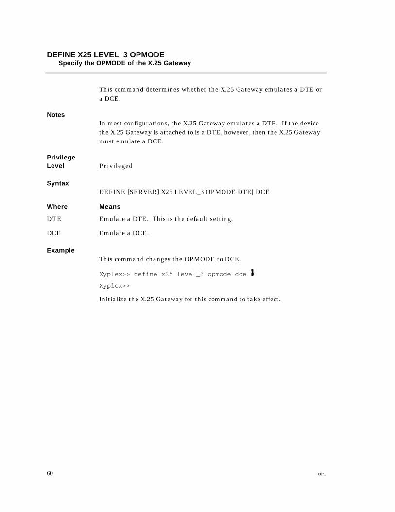
DEFINE X25 LEVEL_3 OPMODESpecify the OPMODE of the X.25 Gateway
This command determines whether the X.25 Gateway emulates a DTE ora DCE.
NotesIn most configurations, the X.25 Gateway emulates a DTE. If the devicethe X.25 Gateway is attached to is a DTE, however, then the X.25 Gatewaymust emulate a DCE.
PrivilegeLevel Privileged
SyntaxDEFINE [SERVER] X25 LEVEL_3 OPMODE DTE|DCE
Where Means
Emulate a DTE. This is the default setting.DTE
DCE Emulate a DCE.
ExampleThis command changes the OPMODE to DCE.
Xyplex>> define x25 level_3 opmode dce
Xyplex>>
Initialize the X.25 Gateway for this command to take effect.
60 0071
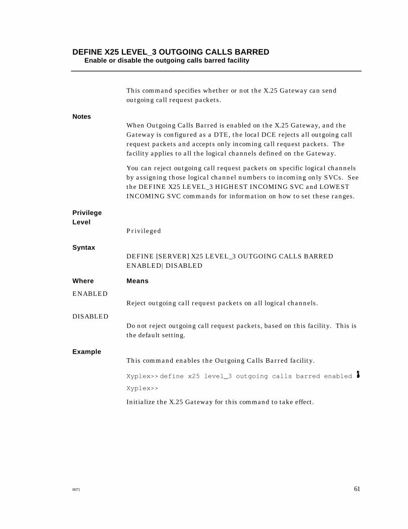
DEFINE X25 LEVEL_3 OUTGOING CALLS BARREDEnable or disable the outgoing calls barred facility
This command specifies whether or not the X.25 Gateway can sendoutgoing call request packets.
NotesWhen Outgoing Calls Barred is enabled on the X.25 Gateway, and theGateway is configured as a DTE, the local DCE rejects all outgoing callrequest packets and accepts only incoming call request packets. Thefacility applies to all the logical channels defined on the Gateway.
You can reject outgoing call request packets on specific logical channelsby assigning those logical channel numbers to incoming only SVCs. Seethe DEFINE X25 LEVEL_3 HIGHEST INCOMING SVC and LOWESTINCOMING SVC commands for information on how to set these ranges.
PrivilegeLevel
Privileged
SyntaxDEFINE [SERVER] X25 LEVEL_3 OUTGOING CALLS BARREDENABLED|DISABLED
Where Means
ENABLEDReject outgoing call request packets on all logical channels.
DISABLEDDo not reject outgoing call request packets, based on this facility. This isthe default setting.
ExampleThis command enables the Outgoing Calls Barred facility.
Xyplex>> define x25 level_3 outgoing calls barred enabled
Xyplex>>
Initialize the X.25 Gateway for this command to take effect.
0071 61

DEFINE X25 LEVEL_3 PACKET RETRANSMISSIONEnable or disable the Packet Retransmission facility
This command specifies whether or not the X.25 Gateway can issue rejectpackets to the network.
NotesWhen a DTE issues a reject packet, it signals the PSN to retransmitunacknowledged data packets, starting with the packet that has thesequence number contained in the reject packet.
PrivilegeLevel Privileged
SyntaxDEFINE [SERVER] X25 LEVEL_3 PACKET RETRANSMISSIONENABLED|DISABLED
Where Means
Allow the X.25 Gateway to issue reject packets.ENABLED
DISABLED Do not allow the X.25 Gateway to issue reject packets. This is the defaultsetting.
ExampleThis command enables the Packet Retransmission facility:.
Xyplex>> define x25 level_3 packet retransmission enabled
Xyplex>>
Initialize the X.25 Gateway for this command to take effect.
62 0071

DEFINE X25 LEVEL_3 R20 R22 R23 R28Specify packet retry counters
These commands specify the values for the X.25 retry counters. The retrycounters determine how many times the X.25 Gateway can send aparticular type of packet after the DTE timeout value for that type of packethas expired.
NotesSee the DEFINE X25 LEVEL_3 T20, T21, T22 T23, T28 commands forinformation about DTE timeout values. Table 2-1 lists the retry countersand their default values.
Table 2-1. Retry Counters
Retry CounterNumber
Packet Type Default
R20 Restart Request packet 255
R22 Reset Request packet 1
R23 Clear Request packet 1
R28 Registration Request packet 1
PrivilegeLevel Privileged
SyntaxDEFINE [SERVER] X25 LEVEL_3 [R20 retry-counter]
[R22 retry-counter][R23 retry-counter][R28 retry-counter]
Where Means
A retry-counter value between 0 and 255.retry-counter
ExampleThis command changes the R22 timeout value to 10:
Xyplex>> define x25 level_3 R22 10
Xyplex>>
Initialize the X.25 Gateway for this command to take effect.
0071 63

DEFINE X25 LEVEL_3 REVERSE CHARGING ACCEPTANCEEnable or disable the Reverse Charging Acceptance facility
This command specifies whether or not the X.25 Gateway can acceptcharges for calls from the PSN with Reverse Charging enabled.
NotesThis facility is disabled by default.
SyntaxDEFINE [SERVER] X25 LEVEL_3 REVERSE CHARGINGACCEPTANCE ENABLED|DISABLED
Where Means
Allow the X.25 Gateway to accept charges for calls from the PSN withReverse Charging enabled.
ENABLED
Do not allow the X.25 Gateway to accept charges for calls from the PSN.DISABLED
ExamplesThis command enables the Reverse Charging Acceptance facility.
Xyplex>> define x25 level_3 reverse charging acceptance enabled
Xyplex>>
Initialize the X.25 Gateway for this command to take effect.
64 0071

DEFINE X25 LEVEL_3 RPOAEnable or disable the RPOA facility
This command specifies whether or not the X.25 Gateway can use a transitnetwork owned by a Registered Private Operating Agency (RPOA) toroute an international call to a destination in another country.
NotesUse this facility to select an international gateway for internationalvirtual calls when more than one such gateway exists, or when theimplementation requires a specific transit network. This facilityrequires that you specify the RPOA gateway identifier, or transit networkidentifier, with the PAD FACILITIES command or the Xyplex X25 PORTFACILITY command.
PrivilegeLevel Privileged
SyntaxDEFINE [SERVER] X25 LEVEL_3 RPOA ENABLED|DISABLED
Where Means
Allow the X.25 Gateway to use a transit network owned by an RPOA toroute an international call, on a per-call basis.
ENABLED
Do not allow the X.25 Gateway to use a transit network owned by anRPOA. This is the default setting for this characteristic.
DISABLED
ExampleThis command enables the RPOA facility.
Xyplex>> define x25 level_3 rpoa enabled
Xyplex>>
Initialize the X.25 Gateway for this command to take effect.
0071 65

DEFINE X25 LEVEL_3 T10 T11 T12 T13Specify DCE timeout values
These commands specify DCE timeout values.
NotesDCE timeouts, along with DTE timeouts, ensure that packet exchangesoccur within a certain period of time. Table 2-2 lists the DCE timeouts andtheir default values.
Table 2-2. DCE Timeouts
TimeoutNumber
Starts When Ends When Default inSeconds
T10 DCE issues a RestartIndication packet
DCE receives a RestartConfirmation packet.
60
T11 DCE issues anIncoming Call packet
DCE receives a CallAccepted or a ClearRequest packet
180
T12 DCE issues a ResetIndication packet
DCE receives a ResetConfirmation packet
60
T13 DCE issues a ClearIndication packet
DCE receives a ClearConfirmation packet
60
PrivilegeLevel Privileged
SyntaxDEFINE [SERVER] X25 LEVEL_3 [T10 timeout-value]
[T11 timeout-value][T12 timeout-value][T13 timeout-value]
Where Means
A DCE timeout value between 0 through 2550, in increments of 10. AllDCE timeout values are in seconds, so you need not specify units.
timeout-value
ExampleThis command changes the T12 timeout value to 80 seconds:
Xyplex>> define x25 level_3 T12 80
Xyplex>>
Initialize the X.25 Gateway for this command to take effect.
66 0071

DEFINE X25 LEVEL_3 T20 T21 T22 T23 T28Specify DTE timeout values
These commands specify DTE timeout values.
NotesDTE timeouts, along with DCE timeouts, ensure that packet exchangesoccur within a certain period of time. Table 2-3 includes the DTEtimeouts and their default values.
Table 2-3. DTE Timeouts
TimeoutNumber
Starts When Ends When Default inSeconds
T20 DTE sends a RestartRequest packet
DTE receives a RestartConfirmation packet
180
T21 DTE sends a CallRequest packet
DTE receives a CallConnected or anIncoming Call packet
200
T22 DTE sends a ResetRequest packet
DTE receives a ResetConfirmation
180
T23 DTE sends a ClearRequest packet
DTE receives a ClearConfirmation packet
180
T28 DTE sends aRegistration Requestpacket
DTE receives aRegistrationConfirmation packet
300
PrivilegeLevel Privileged
SyntaxDEFINE [SERVER] X25 LEVEL_3 [T20 timeout-value]
[T21 timeout-value][T22 timeout-value][T23 timeout-value][T28 timeout-value]
Where Means
A DTE timeout value between 0 through 2550, in increments of 10. AllDTE timeout values are in seconds, so you need not specify units.
timeout-value
0071 67
ExampleThis command changes the T22 timeout value to 120 seconds:
Xyplex>> define x25 level_3 t22 120
Xyplex>>
Initialize the X.25 Gateway for this command to take effect.
68 0071

DEFINE X25 LEVEL_3 THROUGHPUT CLASS NEGOTIATIONEnable or disable the Throughput Class Negotiation facility
This command determines whether the X.25 Gateway can request aparticular throughput class, other than the default class, for each call.
NotesThe term "throughput" refers to the maximum amount of data that theGateway can pass through the network during a specific period of time,when that network is saturated. The maximum possible amount ofthroughput on a virtual circuit depends on several factors includingthese: line speed, local window sizes, and the number of active virtualcircuits on both the local and remote DTE/DCE interface.
Throughput class is expressed in bits-per-second. The default value, 9600bps on the X.25 Gateway, is agreed upon between a user and the PSN atsubscription time. Other possible valid values are 0, 75, 150, 300 , 600, 1200,2400, 4800, 19200, and 48000. (See also the DEFINE X25 LEVEL_3DEFAULT THROUGHPUT CLASS command for information about howto change the default.)
PrivilegeLevel Privileged
SyntaxDEFINE [SERVER] X25 LEVEL_3 THROUGHPUT CLASSNEGOTIATION ENABLED|DISABLED
Where Means
Allow the X.25 Gateway to negotiate a throughput class other than thedefault for each call.
ENABLED
DISABLED Do not allow the X.25 Gateway to negotiate a throughput class other thanthe default. This is the default setting for this facility
ExampleThis command enables the Throughput Class Negotiation facility.
Xyplex>> define x25 level_3 throughput class negotiation enabled
Xyplex>>
Initialize the X.25 Gateway for this command to take effect.
0071 69

DEFINE/SET X25 PORT Commands
The commands in this section specify X.25 Gateway port characteristics. Thesecharacteristics appear in the SHOW/LIST X25 PORT CHARACTERISTICS andthe SHOW/LIST X25 PORT ALTERNATE CHARACTERISTICS displays.
The commands in this section include the following:
DEFINE/SET X25 PORT CONNECT ACTION
DEFINE/SET X25 PORT CONNECT ACTION TYPE
DEFINE/SET X25 PORT CR
DEFINE/SET X25 PORT DEFAULT INBOUND PROFILE
DEFINE/SET X25 PORT DEFAULT OUTBOUND PROFILE
DEFINE/SET X25 PORT DISCONNECT
DEFINE/SET X25 PORT FACILITY
DEFINE X25 PORT PERMANENT SVC
DEFINE X25 PORT PVC DIRECTION
DEFINE X25 PORT PVC LCN
DEFINE/SET X25 PORT REMOTE CLEAR
DEFINE/SET X25 PORT REMOTE PROFILE
70 0071

DEFINE/SET X25 PORT CONNECT ACTIONAssign an X.25 address to one or more of virtual ports
This command assigns an X.25 address to one or more virtual ports.Whenever a user on the LAN makes a connection to that port through LATor Telnet, the X.25 Gateway automatically calls the X.25 address.
NotesUsing this method to call an X.25 address eliminates the need for a LATor Telnet service. You can also create a LAT or Telnet service with aconnect action to an X.25 address, the address in the service will takeprecedence over the address in the port connect action when you call theservice.
SyntaxDEFINE/SET [SERVER] X25 PORT port-list |ALL CONNECT ACTION" address"
Where Means
Assign the X.25 address to these virtual ports.port-list
An X.25 address that the X.25 Gateway will call when a user makes aconnection to one of the virtual ports in the port-list variable. Enclose theaddress in quotes. To remove the association between an X.25 addressand one or more virtual ports, enter a quoted null string (" ")
" address"
Examples1 . This command assigns the address 765432 to ports 50-60.
Xyplex>> set x25 ports 50-60 connect action "765432"
Xyplex>>
2. This command removes the association between an X.25 address andports 50-60.
Xyplex>> set x25 ports 50-60 connect action " "
Xyplex>>
0071 71

DEFINE/SET X25 PORT CONNECT ACTION TYPEAssign a connect action type to one or more virtual ports
This command assigns an X.25 connect action type to one or more virtualports for calls from the X.25 network.
NotesThe X.25 Gateway offers three connect action types: NONE,AUTOCONNECT and USERDATA. NONE is the default, and it causesthe X.25 Gateway to return the Xyplex command interface when a callarrives at a virtual port. AUTOCONNECT connections execute a Xyplexcommand such as CONNECT, which exists in an X.25 service. Thecommand can establish a session with a LAN destination. USERDATAconnections use the information in the D*userdata field of the incomingcall packet as the variable in a CONNECT command. AUTOCONNECTand USERDATA connect actions make network connections more"transparent" to network users, and can enhance Gateway securitybecause you can direct calls to specific destinations.
PrivilegeLevel Nonprivileged
SyntaxDEFINE/SET [SERVER] X25 PORT port-list |ALL CONNECT ACTIONTYPE AUTOCONNECT|USERDATA|NONE
Where Means
port-listAssign a connect action to these virtual ports.
AUTOCONNECT
Assign the AUTOCONNECT connect action type to the ports you specify.
USERDATAAssign the USERDATA connect action type to the ports you specify. (Theuserdata field is limited to 12 characters.)
NONEThis is the default connect action. Use this keyword when you want toremove a previously assigned AUTOCONNECT or USERDATA connectaction from virtual ports.
72 0071

Examples1 . This example assigns the AUTOCONNECT connect action to virtualports 40-45.
Xyplex>> set x25 port 40-45 connect action type autoconnect
After you assign AUTOCONNECT to the virtual ports, you define an X.25service which includes a MAXserver command to establish a session witha LAN device. This example creates a service to establish a session withthe LAN host FinanceVAX, and assigns the listen address 45 to ports 40-45.
Xyplex>> set service x25tofinancevax x25 enabled connect action"connect financevax" x25 address "45" ports 40-45
Xyplex>>
Assuming that at least one of the ports is not busy, calls from the PSNbound for ports 40-45 will automatically establish a session with the LANhost FinanceVAX. The call from the network might look like this,assuming that the master address of the X.25 Gateway is 23612:
CALL 2361245
Call Connected
Welcome to FinanceVAX
Username:
2. This example assigns the USERDATA connect action to virtual ports20-25:
Xyplex>> set x25 port 20-25 connect action type userdata
Xyplex>>
Calls from the network bound for virtual ports 20-25 use a LANdestination name as in the CALL request packet. The call from thenetwork might look like this, assuming that the master address of theX.25 Gateway is 23612:
CALL 2361220D*DEV.SUN.COM
Call Connected
Welcome to DEV.SUN.COM
Username:
0071 73
DEFINE/SET X25 PORT CREnable or disable the carriage return characteristic
This command specifies whether or not the X.25 Gateway sends acarriage return (CR) character to the PAD when a user makes a LANconnection to a virtual port.
NotesIf you make connections directly to the PAD interface through a virtualport, this feature ensures that the PAD prompt appears when you make theconnection to the virtual port. If you make automatic connections todevices on the PSN, you may not want to enable this feature.
PrivilegeLevel Privileged
SyntaxDEFINE/SET [SERVER] X25 PORT port-list |ALL CRENABLED|DISABLED
Where Means
One or more virtual ports.port-list
ENABLED Send a CR character to the PAD when a user makes a LAN connection to avirtual port.
Do not send a CR character to the PAD when a user makes a LANconnection to a virtual port. This is the default setting for thischaracteristic.
DISABLED
ExampleThis example enables the carriage return feature at virtual ports 60-70.
Xyplex>> set x25 ports 60-70 cr enabled
Xyplex>>
74 0071

DEFINE/SET X25 PORT DEFAULT INBOUND PROFILESpecify a default inbound profile for one or more virtual ports
This command assigns a PAD profile to one or more virtual ports forcalls from the PSN bound for a LAN device.
NotesA PAD profile includes 22 PAD parameters. These parameters define theoperating characteristics for an asynchronous device, such as a terminalor printer. The X.25 Gateway PAD can support separate PAD profiles foreach virtual port. The default inbound profile for all virtual ports on theX.25 Gateway is HOST, which has parameters set to support a videoterminal.
Xyplex supplies forty profiles on the X.25 Gateway, including six that aredesigned to support specific devices, such as HOST. These support videoterminals, printers, and different types of data transfer for both inboundand outbound calls. You can modify any of the forty profiles to suit theneeds of your site. See Appendix A for a list of these profiles and theparameter values in each of them.
PrivilegeLevel Privileged
SyntaxDEFINE/SET [SERVER] X25 PORT port-list |ALL DEFAULT INBOUNDPROFILE "profile-name"
Where Means
port-listAssign the default inbound profile to these ports.
" profile-name"Assign this profile to the gateway PAD when calls arrive at the ports youspecify. Enclose the profile name in quotes.
ExampleThis command specifies the PAD profile CRT_NOE as the defaultinbound profile on ports 10-15.
Xyplex>> set x25 port 10-15 default inbound profile "CRT_NOE"
Xyplex>>
0071 75

DEFINE/SET X25 PORT DEFAULT OUTBOUND PROFILEAssign a default outbound profile to one or more virtual ports
This command assigns a PAD profile to one or more virtual ports forcalls from the LAN bound for the PSN.
NotesA PAD profile includes 22 PAD parameters. These parameters define theoperating characteristics for an asynchronous device, such as a terminalor printer. The X.25 Gateway PAD can support different PAD profiles fordifferent virtual ports. The default outbound profile for all virtual portson the X.25 Gateway is CRT, which has parameters set to support videoterminals.
Xyplex supplies forty profiles on the X.25 Gateway, including six that aredesigned to support specific devices, such as HOST. These support videoterminals, printers, and different types of data transfer for both inboundand outbound calls. You can modify any of the forty profiles to suit theneeds of your site. See Appendix A for a list of these profiles and theparameter values in each of them.
PrivilegeLevel Privileged
SyntaxDEFINE/SET [SERVER] X25 PORT port-list|ALL DEFAULTOUTBOUND PROFILE "profile-name"
Where Means
port-listOne or more X.25 Gateway virtual ports where you want to assign adefault outbound profile.
" profile-name"Assign this profile to the X.25 Gateway PAD when calls arrive at the portsyou specify. Enclose the profile name in quotes.
ExampleThis command specifies the PAD profile CRT_NOE as the defaultoutbound profile.
Xyplex>> set x25 port 10-15 default outbound profile "CRT_NOE"
Xyplex>>
76 0071

DEFINE/SET X25 PORT DISCONNECTSpecify the status of the port Disconnect characteristic
This command specifies whether or not the X.25 Gateway disconnects theLAN session when a user clears a virtual circuit made from the PADprompt.
NotesWhen this feature is disabled, you must disconnect the LAN session fromthe Xyplex prompt.
PrivilegeLevel Privileged
SyntaxDEFINE/SET [SERVER] X25 PORT [port-list |ALL] DISCONNECTENABLED|DISABLED
Where Means
One or more virtual ports where you want to enable or disable theDISCONNECT characteristic.
port-list
ALL Enable or disable this characteristic at all virtual ports.
Disconnect the LAN session when a user terminates a virtual circuitfrom the PAD prompt.
ENABLED
Do not disconnect the LAN session when a user terminates a virtualcircuit from the PAD prompt. This is the default setting for thischaracteristic.
DISABLED
ExampleThis command enables the PORT DISCONNECT feature on port 12.
Xyplex>> set x25 port 12 disconnect enabled
Xyplex>>
0071 77

DEFINE/SET X25 PORT FACILITYSpecify per-call facilities for individual virtual ports
This command specifies per-call facilities at the virtual ports you specify.
NotesPer-call facilities enable certain standard X25 user facilities atparticular ports, rather than at all ports as you do with the SERVER X25LEVEL_3 facilities commands. Not all X25 LEVEL_3 facilities areavailable on a per-call basis. Several of the port facilities specify valuesfor X.25 Server Level_3 facilities. In these cases, the Level_3 facilitiesmust be enabled for the port facilities to take effect.
You can also specify per-call facilities with the PAD FACILITIEScommand. See the manual Managing the X25 Gateway for moreinformation about how to use the PAD FACILITIES command.
PrivilegeLevel Privileged
SyntaxDEFINE/SET [SERVER] X25 PORT [port-list |ALL] facility value
DEFINE/SET [SERVER] X25 PORT [port-list |ALL] FACILITY NONE
Where Means
port-list One or more virtual ports where you want to specify per-call userfacilities.
Enable the specified per-call facilities at all virtual ports on the X.25Gateway.
ALL
One of the per-call facilities in Table 2-4, followed by a value for thatfacility from Table 2-5.
facility value
Disable all per-call facilities on the ports you specify starting with thenext virtual call. Existing virtual calls are not affected.
FACILITYNONE
78 0071

Table 2-4. Per-Call Facilities
Facility Function
FAST SELECT Allows the X.25 Gateway to transmit up to 128 bytes of user data in acall request packet.
NUI Specifies a network user identification (NUI) number to the PSN,which can use it to obtain information from the X.25 Gateway forbilling, security, or network management .
PACKET SIZE Determines the packet size that the X.25 Gateway can attempt tonegotiate for calls that originate at the ports you specify. The Level3 Flow Control Parameter Negotiation facility must be enabled tochange the packet size through this facility.
RPOA SELECT Specifies a transit network owned by a registered privateoperating agency (RPOA) that the X.25 Gateway can use to routeinternational calls. The X25 LEVEL_3 RPOA characteristic mustbe set to ENABLED for this per-call facility to take effect.
THROUGHPUTCLASS
Specifies the throughput class for the called DCE and the callingDTE. The LEVEL_3 THROUGHPUT CLASS NEGOTIATIONfacility must be enabled for this per-call facility to take effect
WINDOW SIZE Specifies the maximum number of packets that can remainunacknowledged between the calling and called DTE, that theX.25 Gateway can negotiate for calls that originate at the ports youspecify. The Level 3 Flow Control Parameter Negotiation facilitymust be enabled to change the packet size through this facility.
REVERSECHARGING
Specifies whether or not the X.25 Gateway can request reversecharging for calls that originate at the ports you specify.
0071 79

Table 2-5. Default Values and Ranges for Per-Call Facilities
Facility Value Default Range
FAST SELECT ENABLED|DISABLED DISABLED
NUI " network-user-id" none Up to 38 ASCII characters.
PACKET SIZE called-packet-sizecalling-packet-size
128128
In Octets: 16, 32, 64, 128, 256, 512for both values.
RPOA SELECT " gateway-identifier" none The PSN administrationsupplies gateway identifiers
THROUGHPUTCLASS
called-DCE-classcalling-DCE-class
none 75, 150, 300, 600, 1200, 1200, 2400,4800, 9600, 19200, 48000 for bothvalues.
WINDOW SIZE called-window-size
calling-window-size
2
2
0-7 for both if the Level 3Extended Packet SequenceNumbering facility isDisabled. 0-128 if this facility isenabled. To change the defaultwindow size, the Level 3 FlowControl Parameter Negotiationfacility must be enabled.
REVERSECHARGING
ENABLED|DISABLED DISABLED
Examples1 . This command specifies 256 as the called and calling packet size atports 20-30.
Xyplex>> set x25 ports 20-30 packet size 256 256
Xyplex>>
2. This command enables the Reverse Charging facility at ports 20-30.
Xyplex>> set x25 ports 20-30 reverse charging enabled
Xyplex>>
3. This command disables all per-call facilities at ports 20-30.
Xyplex>> set x25 ports 20-30 facility none
Xyplex>>
80 0071

DEFINE X25 PORT PERMANENT SVCSpecify the status of the PSVC option at one or more virtual ports
This command enables or disables permanent switched virtual circuits(PSVCs) at one or more virtual ports.
NotesPSVCs are a feature on the Xyplex X.25 Gateway; they are not a CCITTstandard virtual circuit type. A PSVC transfers data packets just as aCCITT standard SVC, but it does not come down when you terminate theLAN side of the connection. The logical association between the twoDTEs remains up after you terminate the session.
The PSVC characteristic is disabled at all virtual ports by default. If youenable PSVC support at a virtual port and then disable it, you can establishstandard SVCs at that port. The Show/List Server X25 Port Characteristicsdisplay indicates whether PSVCs are enabled or disabled at a virtual port.
PrivilegeLevel Privileged
SyntaxDEFINE [SERVER] X25 PORT [port-list |ALL] PERMANENT SVCENABLED|DISABLED
Where Means
port-list Enable or disable PSVCs on one or more virtual ports.
Enable or disable PSVCs on all virtual ports.ALL
Activate the PSVC option.ENABLED
DISABLEDDeactivate the PSVC option. This is the default setting for thischaracteristic.
ExampleThis command enables the PSVC option at virtual ports 40-50.
Xyplex>> define x25 port 40-50 permanent svc enabled
Xyplex>>
Initialize the X.25 Gateway for the command to take effect.
0071 81

DEFINE X25 PORT PVC DIRECTIONSpecify the direction of a PVC
This command enables outbound-only PVCs.
NotesWhen a PVC is outbound only, the X.25 Gateway ignores data from thePSN bound for the virtual port associated with the PVC. When a user onthe LAN makes a connection to the virtual port, the X.25 Gatewayestablishes the PVC. Communication is then full duplex. When youdisable this feature, the X.25 Gateway establishes a PVC when calls arriveat the virtual port from the LAN or the PSN.
PrivilegeLevel Privileged
SyntaxDEFINE [SERVER] X25 PORT port-list PVC DIRECTIONOUTBOUND|DISABLED
Where Means
One or more virtual ports associated with PVCs.port-list
OUTBOUND Ignore calls from the PSN at the virtual ports you specify.
The ports you specify are not no longer outbound only.DISABLED
ExampleThis command assigns outbound-only PVCs at ports 22-25.
Xyplex>> define x25 port 22-25 pvc direction outbound
Xyplex>>
This command disables the outbound-only feature for PVCs at ports 22-25.
Xyplex>> define x25 port 22-25 pvc direction disabled
Xyplex>>
Initialize the X.25 Gateway for these commands to take effect.
82 0071
DEFINE X25 PORT PVC LCNAssign a logical channel number to a virtual port for PVC support
This command assigns a logical channel number (LCN) to a virtual portto enable a permanent virtual circuit (PVC) at that port. You assign anLCN to each virtual port individually.
NotesA PVC is a permanent association between two DTEs, such as an X.25Gateway and a remote PAD. To enable a PVC at a port, assign it an LCNthat is within the range of the highest and lowest logical channel numbersspecified in the DEFINE SERVER X25 LEVEL_3 HIGHEST PVC andLEVEL_3 LOWEST PVC commands. The PSN administration assignsthis range.
If you disable a PVC at a port, the port supports SVCs again. The Show/ListServer X25 Port Characteristics display includes the LCN numberassigned to a virtual port, if one exists.
PrivilegeLevel Privileged
SyntaxDEFINE [SERVER] X25 PORT port PVC LCN lcn
DEFINE [SERVER] X25 PORT port-list PVC DISABLED
Where Means
portEnable a PVC at this virtual port. You enable one PVC per port.
Disabled PVCs at one or more virtual ports.port-list
lcnAssign this logical channel number to the virtual port. Be sure that theLCN is within the range of logical channel numbers assigned to PVCs bythe PSN administration.
DISABLEDDeactivate the PVC at one or more virtual ports. When you deactivate thePVC, the X.25 Gateway frees the LCN, and the port supports standardSVCs. This is the default setting for this characteristic.
ExampleThis command assumes that the range of logical channel numbers forPVCs is 30-35.
Xyplex>> define server x25 port 10 pvc lcn 30
Xyplex>>
Initialize the Gateway for the this command to take effect.
0071 83
DEFINE/SET X25 PORT REMOTE CLEARSpecify the status of the remote clear characteristic
This command enables or disables the Remote Clear characteristic.When enabled, the X.25 Gateway sends an Invitation to Clear to theremote device on the PSN when the Gateway terminates the virtual call onthe local virtual port.
NotesYou can enable or disable this characteristic in a local service as well ason a virtual port.
SyntaxDEFINE/SET [SERVER] X25 PORT [port-list|ALL] REMOTE CLEARENABLED|DISABLED
Where Means
One or more virtual ports where you want to enable or disable the RemoteClear characteristic.
port-list
Enable this characteristic at all virtual ports.ALL
Enable the Remote Clear characteristic.ENABLED
Disable the Remote Clear characteristic. This is the default setting.DISABLED
ExampleThis command enables the Remote Clear characteristic at ports 30-40.
Xyplex> set x25 ports 30-40 remote clear enabled
Xyplex>
84 0071

DEFINE/SET X25 PORT REMOTE PROFILEAssign a remote profile to one or more virtual ports
This commands assigns a remote profile to one or more virtual ports.
NotesThe X.25 Gateway sends a remote profile to the remote PAD during avirtual call. If the call is from the LAN, the X.25 Gateway sends aninbound profile to the remote PAD. If the call is from the PSN, the X.25Gateway sends an outbound profile to the remote PAD.
You can include a remote profile in a local service. When you do, the X.25Gateway sends the remote profile when a call reaches a virtual portthrough the service, rather than whenever a call reaches the virtual port.A remote profile in a service takes precedence over a remote profileassigned to a virtual port. See the manual Managing the Xyplex X.25Gateway for more information about remote profiles.
The CLEAR X25 PROFILE command clears parameter values in aprofile, so that the profile includes only those parameters you want to reseton the remote PAD. Only the specified parameters are sent to the remotePAD. See the description of this command for more information on how todo this.
To de-assign a remote profile from a virtual port, enter "null" as the" profile-name" variable.
PrivilegeLevel Privileged
SyntaxDEFINE/SET [SERVER] X25 PORT [port-list |ALL] REMOTE PROFILE" profile-name"
Where Means
One or more virtual ports where you want to assign a remote profile.port-list
The name of the remote profile. Enclose the profile name in quotes. Use"null" to de-assign a remote profile from a virtual port.
" profile-name"
ExampleThis command specifies Hardcopy as the remote profile for callsarriving at ports 10-15. This profile overwrites the default outboundprofile on the remote PAD.
Xyplex>> set x25 port 10-15 remote profile "hardcopy"
Xyplex>>
0071 85
SHOW/LIST/MONITOR Commands
This section describes the SHOW/LIST/MONITOR commands, which createdisplays.
You can abbreviate LEVEL_3 as L3 and LEVEL_2 as L2 in these commands.
The commands in this section include the following:
SHOW/LIST X25 [CHARACTERISTICS]
SHOW/MONITOR X25 COUNTERS
SHOW/LIST X25 PORT [CHARACTERISTICS]
SHOW/LIST X25 PORT ALTERNATE [CHARACTERISTICS]
SHOW/LIST X25 PORT CONNECT ACTION
SHOW/MONITOR X25 PORT STATUS
SHOW/LIST/MONITOR X25 PORT SUMMARY
SHOW/LIST X25 PROFILE
SHOW/MONITOR X25 STATUS
SHOW/LIST X25 LEVEL_1 [CHARACTERISTICS]
SHOW/MONITOR X25 LEVEL_1 STATUS
SHOW/LIST X25 LEVEL_2 [CHARACTERISTICS]
SHOW/MONITOR X25 LEVEL_2 STATUS
SHOW/LIST X25 LEVEL_3 [CHARACTERISTICS]
SHOW/MONITOR X25 LEVEL_3 STATUS
SHOW/LIST SERVICES X25 LOCAL SUMMARY
SHOW/LIST/MONITOR SERVICES [CHARACTERISTICS|STATUS|SUMMARY]
86 0071

SHOW/LIST X25 CHARACTERISTICSDisplay X.25 Gateway server-level characteristics
This display includes some Communications Server characteristics, theX.25 address for the X.25 Gateway, the PAD prompt, and a list of the PADprofiles. This display shows some characteristics that you cannot defineor set.
PrivilegeLevel Nonprivileged
SyntaxSHOW/LIST [SERVER] X25 [SERVER] [CHARACTERISTICS]
Buffer Reserve: 20 Hysteresis: 8 Small Buffer Size: 81 Small Buffer Pool: 566 Large Buffer Size: 128 Large Buffer Pool: 1890 Address: 1 PAD Prompt: \r* Welcome:
Available Profiles:
HOST, CRT, CRT_NOE, CC_SSP, CC_TSP, HARDCOPY, XYPLEX7, XYPLEX8 XYPLEX9, XYPLEX10, XYPLEX11, XYPLEX12, XYPLEX13, XYPLEX14, XYPLEX15, XYPLEX16 XYPLEX17, XYPLEX18, XYPLEX19, XYPLEX20, XYPLEX21, XYPLEX22, XYPLEX23, XYPLEX24 XYPLEX25, XYPLEX26, XYPLEX27, XYPLEX28, XYPLEX29, XYPLEX30, XYPLEX31, XYPLEX32 XYPLEX33, XYPLEX34, XYPLEX35, XYPLEX36, XYPLEX37, XYPLEX38, XYPLEX39, XYPLEX40
Enabled Characteristics: X25
Field Means
The number of "large buffers" the X.25 Gateway can use before it enters a"buffer emergency" flow control state. You cannot define or set thischaracteristic.
BufferReserve
The number of additional buffers above the buffer reserve count, shown inthe "Buffer Reserve" field, which must become available to cancel the"buffer emergency" flow control state. You cannot define or set thischaracteristic.
Hysteresis
The size of small buffers used internally by the PAD. You cannot define orset this characteristic.
Small BufferSize
0071 2-87

Field Means
Small BufferPool
The number of small buffers in the pool. You cannot define or set thischaracteristic.
Large BufferSize
The size of a large buffers used for X.25 packets and frames. Thischaracteristic is affected by the value specified for the level_3 MaximumPacket Size characteristic.
Large BufferPool
The number of large buffers in the pool. This characteristic is not directlyuser-configurable.
The master address for the X.25 Gateway.Address
The message that the X.25 Gateway command interface displays when auser first logs in to the X.25 Gateway.
Welcome
The list of PAD profiles that you can select for inbound or outbound calls.The X.25 Gateway includes forty profiles that you can rename and modify.The profile names shown in this display are those that come predefinedwith the X.25 Gateway. The profile names on your system may bedifferent. The manual Managing the X.25 Gateway describes theseprofiles and how to modify parameter values within them.
AvailableProfiles
EnabledCharact.
When any of the following characteristics appear in this field, they areenabled on the X.25 Gateway:
The status of X.25 communication. If this characteristic appears, X.25communication is enabled. If it does not appear, X.25 communication isdisabled.
X25
The status of the Calling Address characteristic.CallingAddress
The status of the External Loopback Mode characteristic.ExternalLoopback
2-88 0071

SHOW/MONITOR X25 COUNTERSDisplay X.25 Gateway server-level counters
This command displays counters which reflect the accumulated valuessince the counters were last reset to zero.
PrivilegeLevel Monitor/Privileged, Show /Nonprivileged
Syntax
SHOW/MONITOR [SERVER] X25 [SERVER] COUNTERS
MAXx25 V1.3 Rom 440000 HW 00.01.00 Lat Protocol V5.1 Uptime: 0 23:33:32
Address: 08-00-87-00-45-EF Name: X0045EF Number: 0
Level 3 Counters Level 2 Counters
Characters Sent: 212844 Characters Received: 320 Packets Sent: 3915 Transmitted Octet Count: 301096 Packets Received: 320 Transmitter Underruns: 0 Q-Bit Packets Sent: 0 Received Octet Count: 156885 Q-Bit Packets Received: 0 FCS Errors: 0 Reset Packets Sent: 0 Receive Underrun Count: 0 Reset Packets Received: 0 Interrupt Packets Sent: 0 Interrupt Packets Received: 0 Call Requests Sent: 0 Call Accepts Received: 0 Call Requests Received: 80 Call Accepts Sent: 80 X.29 Errors: 0 X.28 Errors: 0
Field Means
The total number of packets sent from level 3, the packet layer, to level 2,the frame layer.
Packets Sent
The total number of packets sent from level 2, the frame layer, to level 3, thepacket layer.
PacketsReceived
The number of Data packets with the qualified bit (Q-bit) set that the X.25Gateway has sent. Setting the Q-bit indicates that the user data in thepacket is a control signal for the remote device, not a message for its user.
Q-Bit PacketsSent
The number of Data packets with the Q-bit set that the X.25 Gateway hasreceived.
Q-Bit PacketsReceived
0071 2-89

Field Means
Reset PacketsSent
The number of level 3 Reset packets sent by the X.25 Gateway.
The number of level 3 Reset packets received by the X.25 Gateway.Reset PacketsReceived
InterruptPackets Sent
The number of level 3 Interrupt packets sent by the X.25 Gateway.
The number of Level 3 Interrupt packets received by the X.25 Gateway.InterruptPacketsReceived
The number of level 3 Call Request packets sent by the X.25 Gateway.Call RequestsSent
The number of Level 3 Call Accepted packets received by the X.25 Gateway.Call AcceptsReceived
Call RequestsReceived
The number of Level 3 Call Request packets received by the X.25 Gateway.
The number of Level 3 Call Accepted packets sent by the X.25 Gateway.Call AcceptsSent
The number of invalid X.29 packets received by the PAD.X.29 Errors
The number of invalid X.28 commands entered at the PAD user interface.X.28 Errors
The number of bytes (octets) transmitted on the X.25 link since the counterswere last reset.
TransmittedOctet Count
The number of times that an incomplete frame was transmitted due to aframe abort or other condition.
TransmitterUnderruns
The number of bytes (octets) received on the X.25 link since the counterswere last reset.
Received OctetCount
The number of received frames which contained an invalid CRC (errorcheck) number.
FCS Errors
ReceiveUnderrunCount
The number of received characters for which there was no storage buffer toreceive them.
2-90 0071

SHOW/LIST X25 PORT CHARACTERISTICSDisplay the X.25 characteristics of a virtual port
This display lists information about a virtual port. This informationincludes the port connect action, whether or not the port is a PVC or aPSVC, and the per-call facilities for the port.
PrivilegeLevel Nonprivileged
SyntaxSHOW/LIST [SERVER] X25 PORT [port-list |ALL][CHARACTERISTICS]
Virtual Port: 5 28 Jan 1994 21:09:43 Conn. Action Type: AUTOCONNECT Permanent SVC: DISABLED PVC LCN: N/A
Packet Size: 128 128 Window Size: 2 2 Throughput Class: 9600 9600 Reverse Charging: DISABLED Fast Select: DISABLED NUI: RPOA Select:
Connect Action
Default Inbound Profile: HOST Default Outbound Profile: CRT
Call Facilities enabled:
Field Means
The virtual port number.Virtual Port
The X.25 connect action type at this virtual port for calls from the PSN to theLAN. Possible connect action types are NONE, AUTOCONNECT, andUSERDATA.
Conn.Action Type
Whether the permanent switched virtual circuit (PSVC) feature is enabledor disabled at this virtual port.
PermanentSVC
The logical channel number of a permanent virtual circuit (PVC), if oneexists, at this virtual port. This field also displays PVC DirectionOutbound if you have enabled the PORT PVC OUTBOUND characteristic.If no PVC exists at this port, the display shows N/A (not applicable) in thisfield.
PVC LCN
The default packet size for calls from this port.Packet Size
The default level 3 window size for calls from this port.Window Size
0071 2-91

Field Means
ThroughputClass
The default throughput class for calls from this port.
ReverseCharging
Whether the reverse charging facility is enabled or disabled at this port.
Fast Select The status of the Fast Select facility: either ENABLED or DISABLED.
The network user identification (NUI) field, if one exists, for this virtualport.
NUI
The Registered Private Operating Agency (RPOA) code, if one exists, forthis virtual port.
RPOA Select
The Connect Action, if one exists, for calls from the LAN to the PSN. TheConnect Action appears as an X.25 address, if one has been assigned. Ifone has not been assigned, this field is blank.
ConnectAction
DefaultInboundProfile
The default profile this virtual port will use with an incoming call.
The default profile this virtual port will use with an outgoing call.DefaultOutboundProfile
Any Level 3 user facilities enabled on the X.25 Gateway. This field alsodisplays the numeric values of per-call facilities if you have specified avalue other than the default.
Call FacilitiesEnabled
2-92 0071

SHOW/LIST X25 PORT ALTERNATE CHARACTERISTICSDisplay the listen address and parameter values of a virtual port
This display includes the listen address, the status of the CRcharacteristic, and current parameters, if any, that apply to a virtual port.
PrivilegeLevel Nonprivileged
SyntaxSHOW/LIST [SERVER] X25 PORT [port-list |ALL] ALTERNATE[CHARACTERISTICS]
Virtual Port: 38 10 Feb 1994 21:41:16 Listen Address: 3338, 3345
Send Carriage Return: Disabled Disconnect: Enabled Remote Clear: Disabled
Current X.3 Parameters: 1: 0 2: 0 3: 0 4: 1 5: 0 6: 5 7: 0 8: 0 9: 0 10: 0 11: 14
12: 0 13: 0 14: 0 15: 0 16: 0 17: 0 18: 0 19: 0 20: 0 21: 0 22: 0
Where Means
The number of the virtual port you specify.Virtual Port
One or more listen addresses assigned to this virtual port. The defaultlisten address is the virtual port number. If you create one or moreservices that assign listen addresses to a virtual port these appear in thedisplay rather than the default.
Listen address
The status of the CR characteristic. When this characteristic is enabled,the X.25 Gateway sends a carriage return (CR) character to the PAD when auser makes a LAN connection to the virtual port. When it is disabled, theX.25 Gateway does not send a CR character to the PAD when a user makes aLAN connection to the virtual port.
Send CarriageReturn
The status of the port Disconnect characteristic. When this characteristicis enabled, the X.25 Gateway disconnects the LAN session when a userclears an X.25 virtual circuit established at the PAD prompt.
Disconnect
The status of the Remote Clear characteristic. When this characteristic isenabled, the X.25 Gateway sends an Invitation-To-Clear to the device onthe PSN when the X.25 Gateway terminates the virtual call on the localvirtual port.
Remote Clear
The parameters of the profile currently in use, if any, at this port. If novirtual circuit is active, this field is blank.
Current X.3Parameters
0071 2-93

SHOW/LIST X25 PORT CONNECT ACTIONDisplay information about automatic connections
This display includes information about the Connect Action Type, theConnect Action, the inbound, outbound, and remote profiles associatedwith the port, and any userdata associated with the port.
PrivilegeLevel Nonprivileged
SyntaxSHOW/LIST [SERVER] X25 PORT [port-list |ALL] CONNECT ACTION
Virtual Port Connect Action Port Connect Userdata Inbound Outbound RemoteAction Profile Profile Profile
3 None 2345 Host CRT
Field Means
The virtual port numberVirtual Port
The Connect Action Type assigned to the virtual port. Possible ConnectAction Types are NONE, AUTOCONNECT, and USERDATA. TheConnect Action Type manages calls from the PSN bound for the X.25Gateway.
ConnectAction
The Port Connect Action, if any, assigned to the virtual port. A PortConnect Action consists of an X.25 address. The X.25 Gatewayautomatically calls this address when a user on the LAN calls the virtualport.
Port ConnectAction
Up to 12 characters of userdata assigned to this virtual port.Userdata
The default inbound profile assigned to this virtual port.InboundProfile
The default outbound profile assigned to this virtual port.OutboundProfile
A remote profile, if any, assigned to this virtual port.Remote Profile
2-94 0071

SHOW/MONITOR X25 PORT STATUSDisplay the status of an X.25 Gateway virtual port
This display includes information about packets that have been passed toand from a virtual port, as well as the current direction of network trafficthrough the virtual port.
PrivilegeLevel Monitor/Privileged, Show/Nonprivileged
SyntaxSHOW/MONITOR [SERVER] X25 PORT [port-list |ALL] STATUS
Virtual Port: 5 28 Jan 1994 21:50:16 Port State: X25 TO LAN SESSION X.25 LCN: 4 Listen Address 05
Characters Sent: 4962 Characters Received: 31 Packets Sent: 85 Packets Received: 30 Q-Bit Packets Sent: 0 Q-Bit Packets Received: 0 Reset Packets Sent: 0 Reset Packets Received: 0 Interrupt Packets Sent: 0 Interrupt Packets Received: 0 Characters Rejected: 0
Field Means
The virtual port number.Virtual Port
Port State The current status of the virtual port. The status messages that can appearin this display are the following: NO SESSION, X25 TO LAN SESSION,LAT/TELNET TO X25 SESSION, AUTOCONNECTING, X25 CALLRECEIVED, LAT/TELNET CONNECT RECEIVED, AUTOCALL INPROGRESS, CLEARING SESSIONS, LAT/TELNET TO X25 CALLWAITING, PVC ESTABLISHED - NO LAN SESSION, PSVCESTABLISHED - NO LAN SESSION, PVC NOT ESTABLISHED, PSVCNOT ESTABLISHED, WAITING FOR PASSWORD, SENDINGPASSWORD PROMPT.
The logical channel number (LCN) for a virtual port with an active virtualcircuit.
X.25 LCN
One or more listen addresses assigned to this virtual port. The defaultlisten address is the virtual port number. If you create one or moreservices that assign listen addresses to a virtual port these appear in thedisplay rather than the default.
ListenAddress
0071 2-95

Field Means
CharactersSent
The number of characters sent by the PAD to level 3.
The number of characters received by the PAD from level 3.CharactersReceived
Packets Sent The number of packets sent to the PSN.
The number of packets received from the PSN.PacketsReceived
The number of DATA packets that the X.25 Gateway sent with the qualifiedbit (Q-bit) set. Setting the Q-bit indicates that the user data in the packet is acontrol signal for the remote device, not a message for its user.
Q-Bit PacketsSent
The number of DATA packets that the X.25 Gateway received with the Q-bitset.
Q-Bit PacketsReceived
Reset PacketsSent
The number of level 3 Reset packets the X.25 Gateway has sent.
The number of level 3 Reset packets the X.25 Gateway has received.Reset PacketsReceived
The number of level 3 Interrupt packets the X.25 Gateway has sent.InterruptPackets Sent
The number of level 3 Interrupt packets the X.25 Gateway has received.InterruptPacketsReceived
The number of characters rejected by level 3.CharactersRejected
2-96 0071

SHOW/LIST/MONITOR X25 PORT SUMMARYDisplay summary information about X.25 Gateway virtual ports
This display shows the connect action for the port you specify andindicates whether or not a session is active at that port.
PrivilegeLevel Monitor/Privileged, Show and List/Nonprivileged
SyntaxSHOW/LIST/MONITOR [SERVER] X25 PORT [port-list |ALL]SUMMARY
Port LCN Connect Action State 19 Feb 1994 20:34:01
10 0 AUTOCONNECT NO SESSION
Field Means
The virtual port number.Port
The logical channel number for this port during an active session.LCN
The connect action type for this virtual port. Possible connect action typesare NONE, AUTOCONNECT, and USERDATA.
ConnectAction
The current status of the virtual port. The status messages that can appearin this display are the following: NO SESSION, X25 TO LAN SESSION,LAT/TELNET TO X25 SESSION, AUTOCONNECTING, X25 CALLRECEIVED, LAT/TELNET CONNECT RECEIVED, AUTOCALL INPROGRESS, CLEARING SESSIONS, LAT/TELNET TO X25 CALLWAITING, PVC ESTABLISHED - NO LAN SESSION, PSVCESTABLISHED - NO LAN SESSION, PVC NOT ESTABLISHED, PSVCNOT ESTABLISHED, WAITING FOR PASSWORD, SENDINGPASSWORD PROMPT.
State
0071 2-97

SHOW/LIST X25 PROFILEDisplay the parameter values of a PAD profile
This display lists all the parameter values of the PAD profile or profilesyou specify. The manual Managing the X.25 Gateway describes eachPAD parameter, and the range of possible values for each PADparameter.
PrivilegeLevel Nonprivileged
Syntax
SHOW/LIST [SERVER] X25 PROFILE ["profile-name" | profile-number|ALL]
Profile 1: HOST
PAD Recall(1): Echo(2): Data Forwarding Character(s)(3): Idle Timer Delay(4): 1 Ancillary Device Control(5): PAD Service Signals Control(6): 5 Break Signal Operation(7): Discard Output(8): Padding after CR(9): Line Folding(10): Binary Speed(11): 14 Flow Control of the PAD(12): Linefeed Insertion after CR(13): Linefeed Padding(14): Editing(15): Character Delete(16): Line Delete(17): Line Display(18): Editing PAD Service Signals(19): Echo Mask(20): Parity Treatment(21): Page Wait(22):
Field Means
The name and number of a PAD profile. The display lists the value of eachparameter in the display.
Profile:
2-98 0071

SHOW/MONITOR X25 STATUSDisplay X.25 server-level status information
This display shows information about buffers and the state of the X.25levels: Line (level 1), Frame (level 2), and Packet (level 3).
PrivilegeLevel Monitor/Privileged, Show/Nonprivileged
Syntax
SHOW/MONITOR [SERVER] X25 [SERVER] STATUS
MAXx25 V1.3 Rom 4C0000 HW 00.01.00 Lat Protocol V5.1 Uptime: 1 18:59:54
Address: 08-00-87-00-45-F0 Name: X0045F0 Number: 0
Large Buffers Available: 1629 Large Buffers In Use: 261 Large Buffers Total: 1890 Large Buffer Allocation Failures: 0 Small Buffers Available: 565 Small Buffers In Use: 1 Small Buffers Total: 566 Small Buffer Allocation Failures: 0
State: Line Up / Frame Up / Packet Up
Field Means
The number of large buffers currently available for use by the PAD.Large BuffersAvailable
Large BuffersIn Use
The number of large buffers currently in use by the PAD.
The total number of large buffers in the system. This amount is the sum ofvalues in the "Large Buffers Available" field and the value in the "LargeBuffers In Use" field.
Large BuffersTotal
The number of times when the X.25 Gateway could not allocate largebuffers.
Large BufferAllocationFailures
The number of small buffers currently in the free pool.Small BuffersAvailable
Shows the number of small buffers currently in use by the PAD.Small BuffersIn Use
0071 2-99

Field Means
Small BuffersTotal
Shows the total number of small buffers in the system (sum of "SmallBuffers Available" and "Small Buffers In Use" fields).
Shows the number of occurrences when small buffers could not be allocatedby the system.
Small BufferAllocationFailures
State Shows the condition, up or down, of the different network levels. Thephysical layer, layer 1, corresponds to the Line state; the data-link level,layer 2, corresponds to the Frame state; the network level, level 3,corresponds to the Packet state.
2-100 0071

SHOW/LIST X25 LEVEL_1 CHARACTERISTICSDisplay level 1 characteristics
This display includes information about level 1, the physical layer, of theX.25 Gateway. You can not change most level 1 characteristics.
PrivilegeLevel Nonprivileged
SyntaxSHOW/LIST [SERVER] X25 LEVEL_1 [CHARACTERISTICS]
Address: 08-00-87-00-45-F0 Name: X0045F0 Number: 0
Baud Rate: EXTERNAL Receive Queue Size: 16 Transmit Queue Size: 20 Frame Retry Limit: 4 Data Encoding: NRZ
Field Means
The speed setting for the link. EXTERNAL indicates that the link speed isset with an external clock. See the X25 Level_1 Status display to see theactual speed.
Baud Rate
The size of the level 1 receive queue.ReceiveQueue Size
The size of the level 1 transmit queue.TransmitQueue Size
The number of retries to be used by the link driver.Frame RetryLimit
The data encoding technique used by the hardware (permanently set toNRZ).
DataEncoding
0010 2-101

SHOW/MONITOR X25 LEVEL_1 STATUSDisplay level 1 status
This display shows information about the status of signals and linkspeeds.
PrivilegeLevel Monitor/Privileged, Show/Nonprivileged
SyntaxSHOW/MONITOR [SERVER] X25 LEVEL_1 STATUS
Address: 08-00-87-00-45-F0 Name: X0045F0 Number: 0
State: Up
Transmit Link Speed: 66.60 Kbps Receive Link Speed: 66.70 Kbps DTR: ASSERTED RTS: ASSERTED DSR: OBSERVED DCD: OBSERVED CTS: OBSERVED
Field Means
The speed that the X.25 Gateway is transmitting data, in megabits-per-second. The speed is set with an external clocking signal.
TransmitLink Speed
The speed that the X.25 Gateway is receiving data, in megabits-per-second.The speed is set with an external clocking signal.
Receive LinkSpeed
Whether or not the X.25 Gateway card has asserted the Data TerminalReady (DTR) signal.
DTR
Whether or not the X.25 Gateway card has asserted the Request to Send(RTS) signal.
RTS
Whether or not the X.25 Gateway card has observed the Data Set Ready(DSR) signal.
DSR
Whether or not the X.25 Gateway card has observed the Data Carrier Detect(DCD) signal.
DCD
Whether or not the X.25 Gateway card has observed the Clear to Send (CTS)signal.
CTS
2-102 0071

SHOW/LIST X25 LEVEL_2 CHARACTERISTICSDisplay level 2 characteristics
This display includes information about Level 2, the frame layer.
PrivilegeLevel Nonprivileged
SyntaxSHOW/LIST [SERVER] X25 LEVEL_2 [CHARACTERISTICS]
Address: 08-00-87-00-45-F0 Name: X0045F0 Number: 0
Protocol: LAPB Opmode: DTE Window Size: 7 T1: 3 SECONDS T2: 2 SECONDS T3: 0 SECONDS N2 Counter: 20
X.2 Facilities Enabled:
Field Means
The frame layer protocol, which determines the frame exchangeprocedures that the X.25 Gateway uses. All X.25 Gateways use the linkaccess protocol balanced (LAPB) protocol.
Protocol
The frame layer OPMODE, which is either a logical DTE or a logicalDCE. The X25 Level_3 OPMODE characteristic determines this setting.
Opmode
The frame layer window size, which is the number of previously sent framesthat can remain unacknowledged at any time between a DTE and a DCE TheX25 Level_2 Window Size characteristic determines this setting.
Window Size
T1 The amount of time that the X.25 Gateway will wait for anacknowledgment of a transmitted frame with a bit set (the P bit) thatrequests immediate acknowledgment. After this time limit, the gatewayretransmits that frame. The X25 Level_2 T1 characteristic determinesthis setting.
How long the X.25 Gateway can wait to acknowledge receipt of a message.The X25 Level_2 T2 characteristic determines this setting.
T2
How long a channel can be idle before the X.25 Gateway resets the link.The X25 Level_2 T3 characteristic determines this setting.
T3
The maximum number of times that the X.25 Gateway can retransmit anunacknowledged frame before it resets the link.
N2
The Level 2 facilities that can appear in this field include Extended FrameSequence Numbering, if it is enabled.
X.2 Facilities
0071 2-103

SHOW/MONITOR X25 LEVEL_2 STATUSDisplay level 2 status
This display shows information about level 2, the frame layer.
PrivilegeLevel Monitor/Privileged, Show/Nonprivileged
SyntaxSHOW/MONITOR [SERVER] X25 LEVEL_2 STATUS
Address: 08-00-87-00-45-F0 Name: X0045F0 Number: 0
State: Up Transmitted Octet Count: 5851 Transmitter Underruns: 0 Received Octet Count: 953 FCS Errors: 0 Receive Underrun Count: 0
Field Means
Whether the X.25 Gateway level 2, the frame layer, is up or down.State
The total number of bytes (octets) transmitted on the X.25 link since thecounters were last reset.
TransmittedOctet Count
The number of times that an incomplete frame was transmitted due to aframe abort or other condition.
TransmitterUnderruns
The total number of bytes (octets) received on the X.25 link since thecounters were last reset.
Received OctetCount
The number of received frames which contained an invalid CRC (errorcheck) number.
FCS Errors
ReceiveUnderrunCount
The number of times that the Gateway lost data from the X.25 networkbecause of an insufficient number of storage buffers.
2-104 0071
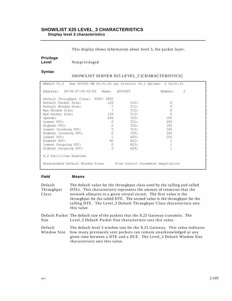
SHOW/LIST X25 LEVEL_3 CHARACTERISTICSDisplay level 3 characteristics
This display shows information about level 3, the packet layer.
PrivilegeLevel Nonprivileged
SyntaxSHOW/LIST SERVER X25 LEVEL_3 [CHARACTERISTICS]
MAXx25 V1.3 Rom 4C0000 HW 00.01.00 Lat Protocol V5.1 Uptime: 0 02:51:31
Address: 08-00-87-00-45-F0 Name: X0045F0 Number: 0
Default Throughput Class: 9600/ 9600 Default Packet Size: 128 T10: 0 Default Window Size: 7 T11: 0 Max Window Size: 7 T12: 0 Max Packet Size: 128 T13: 0 Opmode: DTE T20: 180 Lowest PVC: 0 T21: 200 Highest PVC: 0 T22: 180 Lowest Incoming SVC: 0 T23: 180 Highest Incoming SVC: 0 T28: 300 Lowest SVC: 1 R20: 255 Highest SVC: 80 R22: 1 Lowest Outgoing SVC: 0 R23: 1 Highest Outgoing SVC: 0 R28: 1
X.2 Facilities Enabled:
Nonstandard Default Window Sizes Flow Control Parameter Negotiation
Field Means
The default value for the throughput class used by the calling and calledDTEs. This characteristic represents the amount of resources that thenetwork allocates to a given virtual circuit. The first value is thethroughput for the called DTE. The second value is the throughput for thecalling DTE. The Level_3 Default Throughput Class characteristic setsthis value
DefaultThroughputClass
The default size of the packets that the X.25 Gateway transmits. TheLevel_3 Default Packet Size characteristic sets this value.
Default PacketSize
The default level 3 window size for the X.25 Gateway. This value indicateshow many previously sent packets can remain unacknowledged at anygiven time between a DTE and a DCE. The Level_3 Default Window Sizecharacteristic sets this value.
DefaultWindow Size
0071 2-105

Field Means
Max WindowSize
The current maximum value for the window size.
Max PacketSize
The current maximum value for the packet size.
Whether the X.25 Gateway is configured as a logical DTE or a logicalDCE.
Opmode
The lowest logical channel number in the range of LCNs that are assignedto permanent virtual circuits (PVCs).
Lowest PVC
The highest logical channel number in the range of LCNs that areassigned to permanent virtual circuits (PVCs).
Highest PVC
The lowest logical channel number for one-way incoming SVCs.LowestIncoming SVC
The highest logical channel number for one-way incoming SVCs.HighestIncoming SVC
The lowest logical channel number for two-way SVCs.Lowest SVC
The highest logical channel number for two-way SVCs.Highest SVC
The lowest logical channel number for one-way outgoing SVCs.LowestOutgoing SVC
The highest logical channel number for one-way outgoing SVCs.HighestOutgoing SVC
The user facilities enabled on the X.25 Gateway. These facilities caninclude the following: DBIT Modification, Extended Packet SequenceNumbering, Fast Select Acceptance, Flow Control Parameter Negotiation,Incoming Calls Barred, Local Charge Prevention, NUI, Outgoing CallsBarred, One Way Logical Channel Incoming, One Way Logical ChannelOutgoing, Packet Retransmission, RPOA, Reverse Charge Acceptance,Throughput Class Negotiation.
X.2 FacilitiesEnabled
The values of the DCE timeoutsT10, T11, T12,T13
The values of the DTE timeoutsT20, T21, T22,T23, T28
The values of the packet retry counters.R20, R22, R23,R28
2-106 0071

SHOW/MONITOR X25 LEVEL_3 STATUSDisplay level 3 status
This display lists information about level 3, the packet layer.
PrivilegeLevel Monitor/Privileged, Show/Nonprivileged
SyntaxSHOW/MONITOR [SERVER] X25 LEVEL_3 STATUS
Address: 08-00-87-00-45-F0 Name: X0045F0 Number: 0
State: Up Characters Sent: 82 Characters Received: 1 Packets Sent: 1 Packets Received: 1 Q-Bit Packets Sent: 0 Q-Bit Packets Received: 0 Reset Packets Sent: 0 Reset Packets Received: 0 Interrupt Packets Sent: 0 Interrupt Packets Received: 0 Call Requests Sent: 2 Call Accepts Received: 0 Call Requests Received: 2 Call Accepts Sent: 2 X.29 Errors: 0 X.28 Errors: 0
Field Means
Whether the X.25 Gateway packet layer, level 3, is up or down.State
The total number of packets sent from the packet layer, level 3, to the framelayer, layer 2.
Packets Sent
The total number of packets sent from the frame layer, level 2, to the packetlayer, level 3.
PacketsReceived
The number of Data packets sent that the X.25 Gateway has sent with the Q(qualified) bit set. Setting the Q bit indicates that the user data in the packetis a control signal for the remote device, not a message for its user.
Q-Bit PacketsSent
The number of Data packets received by the X.25 Gateway, with the Q(qualified) bit set.
Q-Bit PacketsReceived
The number level 3 Reset packets sent by the X.25 Gateway.Reset PacketsSent
0071 2-107

Field Means
Reset PacketsReceived
The number level 3 Reset packets the X.25 Gateway has received.
InterruptPackets Sent
The number level 3 Interrupt packets that the X.25 Gateway has sent.
InterruptPacketsReceived
The number level 3 Interrupt packets that the X.25 Gateway has received.
The number of level 3 Call Request packets that the X.25 Gateway has sent.Call RequestsSent
The number level 3 Call Accepted packets that the X.25 Gateway hasreceived.
Call AcceptsReceived
The number level 3 Call Request packets that the X.25 Gateway hasreceived.
Call RequestsReceived
Call AcceptsSent
The number level 3 Call Accepted packets that the X.25 Gateway has sent.
The number of invalid X.29 packets that the PAD has received.X.29 Errors
The number of invalid X.28 commands entered at the PAD user interface.X.28 Errors
2-108 0071

SHOW SERVICES LOCAL X25 SUMMARYDisplay summary information about X.25 services
This display shows information about X25 services. This informationincludes the service name and, if they exist in the service, the listenaddress, the X.25 profile, and the remote profile.
PrivilegeLevel Nonprivileged
SyntaxSHOW SERVICE S LOCAL X25 SUMMARY
Service Name Listen Address Profile Remote Profile
dev.sun.com 90 Xyplex20
financevax 23 CRT_NOE
Field Means
The name of this local X25 service.Service Name
A nondefault listen address assigned to one or more virtual portsassociated with this local service.
ListenAddress
A local profile which applies to one or more virtual ports while this serviceis active.
Profile
A remote profile which applies to one or more virtual ports while thisservice is active.
Remote Profile
0071 2-109
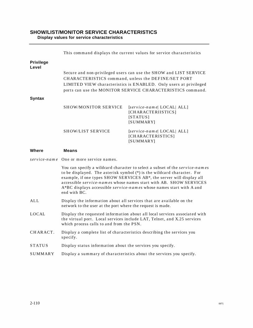
SHOW/LIST/MONITOR SERVICE CHARACTERISTICSDisplay values for service characteristics
This command displays the current values for service characteristics
PrivilegeLevel
Secure and non-privileged users can use the SHOW and LIST SERVICECHARACTERISTICS command, unless the DEFINE/SET PORTLIMITED VIEW characteristics is ENABLED. Only users at privilegedports can use the MONITOR SERVICE CHARACTERISTICS command.
Syntax
SHOW/MONITOR SERVICE [service-name|LOCAL|ALL][CHARACTERIISTICS][STATUS][SUMMARY]
SHOW/LIST SERVICE [service-name|LOCAL|ALL][CHARACTERISTICS][SUMMARY]
Where Means
One or more service names.
You can specify a wildcard character to select a subset of the service-namesto be displayed. The asterisk symbol (*) is the wildcard character. Forexample, if one types SHOW SERVICES AB*, the server will display allaccessible service-names whose names start with AB. SHOW SERVICESA*BC displays accessible service-names whose names start with A andend with BC.
service-name
Display the information about all services that are available on thenetwork to the user at the port where the request is made.
ALL
Display the requested information about all local services associated withthe virtual port. Local services include LAT, Telnet, and X.25 serviceswhich process calls to and from the PSN.
LOCAL
Display a complete list of characteristics describing the services youspecify.
CHARACT.
Display status information about the services you specify.STATUS
Display a summary of characteristics about the services you specify.SUMMARY
2-110 0071

Service: FINANCE VAX 08 Jan 1994 17:55:59
Identification: Corporate MicroVAX II
Service: PRINTER 08 Jan 1994 17:55:59
Identification: Terminal Server Printer Queue
Ports: 2, 7
Rating: 127
Connect Action:
Internet Address:
Listen Address
X25 Profile
X25 Remote Profile:
Enabled Characteristics:
Field Means
The name of a service available on the network.Service
A text string which identifies the service, or describes how to use theservice.
Identification
Shows the numbers of the port(s) on the terminal server where locallyoffered services are available.
Ports
Shows the relative availability of the service. If there are any availableports which offer the service, then the rating shown is proportional to thenumber of available ports. This field is always 0 for an X.25 service.).
Rating
The connect action in the service. In LAT and Telnet services, the connectaction is an X.25 address. In X.25 services, the connect action is a Xyplexcommand, such as CONNECT, and a LAN destination name or Internetaddress.
ConnectAction
The Internet address of a host on the LAN, if one is defined in a Telnetservice.
InternetAddress
A nondefault listen address in an X.25 service, if one is defined. Thisfield is always blank in a LAT or Telnet Service.
X25 ListenAddress
X25 Profile A local profile, if one is defined in the service.
A remote profile, if one is defined in the service.X25 RemoteProfile
Shows the characteristics that have been enabled for the local service usingDEFINE/SET SERVICE commands. These characteristics include thefollowing:
EnabledCharacteristic
End of Chapter
0071 2-111

Appendix A
PAD Profiles
Table A-1 lists the default parameter values, if they are set, for the X.25 Gateway profiles.Some parameters do not have a value set by default. If this is the case, the table shows n/v(no value), in place of a parameter value.
0071 112

DEFINE/SET SERVICE
Table A-1. Default Parameter Values in PAD Profiles
Parameters Profiles
HOST CC_SSP CC_TSP CRT HARDCOPY
CRT_NOE XYPLEX7-40
1 PAD Recall n/v 1 n/v 64 64 64 n/v
2 Echo n/v n/v n/v 1 1 n/v n/v
3DataForwarding
n/v 2 n/v 127 2 127 n/v
4 Idle Timer 1 n/v 2 2 n/v 2 1
5AncillaryDevice Code
n/v n/v n/v n/v 2 n/v n/v
6 Control of PADService Signals
5 5 n/v 5 5 5 n/v
7 PAD Operationof Receipt of Break
n/v 21 21 2 21 2 n/v
8 PAD Discard n/v n/v n/v n/v n/v n/v n/v
9 Padding After<CR>
n/v n/v n/v n/v 5 n/v n/v
1 0 Line Folding n/v n/v n/v n/v 80 n/v n/v
1 1 Binary Speed 14 14 14 14 n/v 14 14
1 2 PAD FlowControl
n/v n/v n/v 1 1 1 n/v
1 3 LinefeedInsert After <CR>
n/v n/v n/v 4 4 4 n/v
1 4 LinefeedPadding
n/v n/v n/v n/v 5 n/v n/v
1 5 PAD Editing n/v n/v n/v n/v 1 n/v n/v
16 CharacterDelete
n/v 127 n/v 127 8 127 n/v
1 7 Line Delete n/v 24 n/v 24 24 24 n/v
1 8 Line Display n/v 18 n/v 18 18 18 n/v
1 9 Editing PADService Signals
n/v 3 3 2 1 2 n/v
20 Echo Mask n/v n/v n/v n/v n/v n/v n/v
2 1 ParityTreatment
n/v n/v n/v 3 3 3 n/v
22 Page Wait n/v n/v n/v n/v n/v n/v n/v
113

Appendix B
PAD Commands
CALL [?]|[[address] [*P|*Duser-data]]
CLR
FACILITIES [*|facilities]
FULL
HALF [*]|[[-] ch1, ch2, . . . chn]
HELP
INTERRUPT
LISTEN [ADDR=address|DATA=user-data]
PAR? [ref1,[ref2,...,refn]]
PROF [?|profile]
RESET
RICLR
RPAR? [ref1[,ref2,...,refn]]
RPROF [profile|?]
RSET [ref1:val1[,ref2:val2,...,refn :valn]]
RSET? [ref1:val1,[,ref2:val2,...,refn:valn]]
SET [ref1:val1[,ref2:val2,...,refn:valn]]
SET? [ref1:val1[,ref2:val2,...,refn:valn]]
STATUS
TABS [LCL tab-num] [REM tab-num] [EXP exp-num]
End of Appendix
0071 114