The Wood Products Council The AIA/CES High Load … · Diaphragm Design Example Rigid vs. Flexible...
25
High Load Diaphragm Design f P li dR f for Panelized Roofs A Cost Effective Solution for Large Low Slope Roofs Lisa Podesto, PE Technical Director “The Wood Products Council” is a Registered Provider with The American Institute of Architects Continuing Education Systems (AIA/CES). Credit(s) earned on completion of this program will be reported to AIA/CES for AIA members. Certificates of Completion for both AIA members and non-AIA members are available upon request. This program is registered with AIA/CES for continuing professional education. As such, it does not include content that may be deemed or construed to be an approval or endorsement by the AIA of any t il f t ti th d fh dli i material of construction or any method or manner of handling, using, distributing, or dealing in any material or product. Questions related to specific materials, methods, and services will be addressed at the conclusion of this presentation. Copyright Materials This presentation is protected by US and International Copyright laws Reproduction International Copyright laws. Reproduction, distribution, display and use of the presentation without written permission of the speaker is prohibited prohibited. © The Wood Products Council 2010 © The Wood Products Council 2010 Learning Objectives At the end of this program, participants will be able to: 1 Hi hli ht i t t hi h l d di h d ti li 1. Highlight important high load diaphragm detialing 2. Explore sub diaphragm design techniques 3. Introduce the collective chord modification theory 4. Discover high load effects on diaphragm deflection
Transcript of The Wood Products Council The AIA/CES High Load … · Diaphragm Design Example Rigid vs. Flexible...

High Load Diaphragm Designf P li d R ffor Panelized Roofs
A Cost Effective Solution for Large Low Slope RoofsLisa Podesto, PE
Technical Director
“The Wood Products Council” is a Registered Provider with The American Institute of Architects Continuing Education Systems (AIA/CES). Credit(s) earned on completion of this program will be ( ) ( ) p p greported to AIA/CES for AIA members. Certificates of Completion for both AIA members and non-AIA members are available upon request.
This program is registered with AIA/CES for continuing professional education. As such, it does not include content that may be deemed or construed to be an approval or endorsement by the AIA of any
t i l f t ti th d f h dli imaterial of construction or any method or manner of handling, using, distributing, or dealing in any material or product.
Questions related to specific materials, methods, and services will be addressed at the conclusion of this presentation.
Copyright Materials
This presentation is protected by US and International Copyright laws ReproductionInternational Copyright laws. Reproduction,
distribution, display and use of the presentation without written permission of the speaker is
prohibitedprohibited.
© The Wood Products Council 2010© The Wood Products Council 2010
Learning Objectives
At the end of this program, participants will be able to:
1 Hi hli ht i t t hi h l d di h d ti li1. Highlight important high load diaphragm detialing
2. Explore sub diaphragm design techniques
3. Introduce the collective chord modification theoryy
4. Discover high load effects on diaphragm deflection

Overview
C l l ti M th d Calculation Methods Rigid vs. FlexibleHigh Load Diaphragm TableHigh Load Diaphragm TableSub-diaphragmsCollective Chord designCollective Chord designDiaphragm Deflection
Diaphragm Design Example
Rigid vs. Flexible Wood Diaphragms
Flexible, Rigid and Semi-Rigid Diaphragms
Flexible Diaphragm load is distributed to shear walls by
tributary area Rigid Diaphragm load is distributed to shear walls by wall
stiffness and torsionstiffness and torsion Semi-rigid Between flexible and rigid dependent on stiffness Between flexible and rigid, dependent on stiffness
Diaphragm (Plan View)
w
L/2 L/2

Flexible Diaphragm
w
sw
.25wL .25wL.50wLFlexible
di
L/2 L/2L/2 L/2
Rigid – All walls Identical
w
sw
.333wL .333wL.333wLRigid (noTorsion)Torsion)
L/2 L/2
Flexible vs. Rigid
w
2K 2KKStiffness
.25wL .25wL.50wLFlexible
Rigid (noTorsion)
.40wL .40wL.20wL
L/2 L/2L/2 L/2
Flexible, Rigid or Semi-Rigid
Which do you have? Prescribed flexible Calculated flexible Prescribed rigid Prescribed rigid Else, “semi-rigid”

Prescribed Flexible Diaphragm
In many cases wood diaphragms are permittedIn many cases wood diaphragms are permitted to be idealized as flexible
ASCE 7-05 Sec. 12.3.1.1 exempts one- and two-family dwellings from rigid diaphragm analysisdwellings from rigid diaphragm analysis.
CBC 2007 Sec 1613.6.1 adds following text to the ASCE provisions.
Prescribed Flexible Diaphragm
CBC 2007 Sec. 1613.6.1 Diaphragms constructed of wood structural panels….
Shall also be permitted to be idealized as flexible,Shall also be permitted to be idealized as flexible,provided all of the following conditions are met:
Prescribed Flexible Diaphragm
1 C t t i i t t l d i l th 1 51. Concrete topping is non-structural and is less than 1.5 in.
2 Each line of vertical elements of LFRS complies with2. Each line of vertical elements of LFRS complies with allowable story drift of ASCE7-05 Table 12.12-1
3 Vertical elements of LFRS are light framed walls3. Vertical elements of LFRS are light framed walls sheathed with wood structural panels or steel sheets
4. Cantilever portions of the diaphragm designed in4. Cantilever portions of the diaphragm designed in accordance with Sec. 2305.2.5
Calculated Flexible Diaphragm
ASCE 7-05 Sec. 12.3.1.3Diaphragms are permitted to be idealized as fl ibl hflexible when: The diaphragm deflection is more than two times the
average story drift of adjoining shear wallsaverage story drift of adjoining shear walls
2 DIAPHRAGM 2 x SHEARWALLS

Calculated Flexible Diaphragm
SHEARWALLS
(Average Deflection) SHEARWALLS
DIAPHRAGM
The longer the diaphragm the morediaphragm the more likely it is to calculate as flexible
Prescribed Rigid Wood Diaphragms (CBC 2305.2.5)
Open front Cantilevered diaphragmsg
Semi-Rigid Diaphragm
Semi-rigid results in force distribution somewhere between rigid and flexible Thus, an envelope approach can be used
where the both rigid and flexible models are used and the highest forces from each are selected
Deflections (4-term eqn’s)
Shear Wall (IBC §2305.3.2)
adbhhe
tGvh
EAbvh
n 75.08 3
Diaphragm (IBC §2305.2.2)
vv btGEAb
bX
LetG
vLEAbvL c
n
2)(
188.048
5 3
btGEAb vv 248
APA L350 (www.apawood.org) has comprehensive li ti f i t t d llisting of input parameters and examples

Deflections (4-term equations)
Diaphragm (CBC 2305.2.2)
bending shear nail slip chord connection slipTotal bb vv nn cc
bX
LetG
vLEAbvL c
n
2)(
188.048
5 3
SDPWS –
btGEAb vv 248
0.25 v L 1000Ga
SDPWS unblocked and bl k d1000Ga blocked
Deflections (4-term equations)
Shear Wall (CBC 2305.3.2)Total bb vv nn aaTotal bb vv nn aa
dhhevhvh 7508 3
bending shear nail slip anchorage slip
a
vv
db
hetGEAb
n 75.0
v h 1000Ga
SPDWS
APA L350 (www.apawood.org) has comprehensive listing of input parameters and examples
1000Ga
g p p p
Deflection (3-term eqn.)
Diaphragm (SDPWS §4.2.2)Diaphragm (SDPWS §4.2.2)
XvLvL c )(2505 3 W
XGvL
EAWvL c
a 2)(
100025.0
85
Ga values for blocked and unblocked diaphragms
Diaphragms and Shear Walls
Deflection of Unblocked Diaphragms is 2.5 times the deflection of blocked diaphragm.p g
If framing members are spaced more than 24”o.c., testing indicates further deflection increase of about 20% or 3 times the deflection offurther deflection increase of about 20%, or 3 times the deflection of a comparable blocked diaphragm. (This is based on limited testing of the diaphragm by APA)
Large & High Load Diaphragms How to design for lateral loads
Table 4.2B in SDPWS referenced in 2009 IBC
High Load Diaphragm Design Table 4.2B in SDPWS referenced in 2009 IBC Based on APA full scale testing APA report 138 ES 1952 now incorporated in code
3x normal diaphragm shear values 1800 plf ASD for seismic 1800 plf – ASD for seismic 2520 plf - ASD for wind
40% increase for wind loads All edges are blocked 8’-10’ panel width with purlins at each end
Utilizes multiple rows of nails
Fastener Pattern – Figure 4C in 2008 SDPWS for use with High-Load Diaphragm Table
4” nominal three lines
3” nominal two lines

Avoid Nail Splitting
2X4 3X4Slide provided by John Lawson, S.E., Kramer and Lawson
4.2.7.1 notesHigh-Load Diaphragm Table
Loads were limited by lumber splitting
High Load Diaphragm Table
Loads were limited by lumber splitting.
2 x 42 x 4
Clarification to High Load Diaphragm Table
Intermediate NailingMaximum spacing 12” o.c.Exception: 6” o c for spans greater thanException: 6 o.c for spans greater than
32” o.c.
Intermediate Member Size2x framing allowed at intermediate framing members where fasteners are 12” or 6” o cmembers where fasteners are 12 or 6 o.c.
Notes to High Load Diaphragm Table
Th h l i th t bl f 1 d The shear values in the table are for cases 1 and 2
The shear values are applicable to cases 3 4 5 The shear values are applicable to cases 3,4,5 and 6 provided fasteners at all continuous edges are spaced in accordance with the boundary fastener spacing

Diaphragm Layout Cases
Load Perpendicular to Cont. Edge
Load Parallel to Cont. Edge
Clarification to High Load Diaphragm Table
Boundary, edge and intermediate nailing(case 1 and 2)
Continuous Panel Edge Nailing (Panel Edge Nailing- for case 1, 2Boundary Nailing for caseBoundary Nailing - for case3,4,5 and 6)
Boundary N ili
Intermediate Nailing
Nailing
Note: Framing omitted for clarityPanel Edge
Nailingg
Clarification to High Load Diaphragm Table
B d d d i t di t iliBoundary, edge and intermediate nailing(case 3,4,5,6)
Boundary Nailing
Edge Nailing
(use boundary nailing at ti d tNailing
Field Nailing
continuous edge per note d.)
Nailing
Note: Framing omitted for clarity
Seismic Diaphragm-to-Wall Anchorage Forces

Sub-diaphragm Concept
Sub-diaphragm is a portion of a larger wood diaphragm designed to anchor and transfer localdiaphragm designed to anchor and transfer local forces to primary diaphragm struts and main diaphragm (2006 IBC 2302.1)p g ( )
Advantages
Eliminates the need for long-span design of walls forEliminates the need for long span design of walls for out-of-plane bending
Transfers anchorage forces to main members, thus reducing the number of connections required to fulfill continuous cross tie requirements.
Members used as cross-ties are typically better Members used as cross-ties are typically better suited for accommodating the necessary connections
Reduces cost – the larger the roof the greater are the savings provided by the use of sub-diaphragms.
How to design for lateral loads
Normal Diaphragm Design
Connections required foreach line of sub-purlins
Lateral Load
1800= 1800connections
How to design for lateral loads
Sub-Diaphragm Design
T i l l d t fTypical load transfer
Lateral Load = 102= 102
connections
Aspect ratio 2.5:1 max.

How to design for lateral loads
Normal Diaphragm Design
Connections required forh li f li
Lateral Load
each line of purlins
Typical Load Transfer
Subdiaphragm (Typical) – max aspect ratio = 2 5:1ratio = 2.5:1
Subdiaphragm is designed the same as a diaphragm
Sub-diaphragm Summary
f h h bd h f Use of the the subdiaphragm concept often reduces number of connectionsR d t f d f Reduces cost of wood roofs
APA document (Z350) provides connection details and has tables to aid the designerdetails and has tables to aid the designer
Reference
Examples: Sub-diaphragmsContinuous cross-tiesAnchorage details
APA Publication Z350

Reference
Examples: Diaphragms DesignSub-diaphragm DesignDeflection Calculations
APA Publication L350
How to design for lateral loads
W k ll ll d d t i b ildi
Traditional Chord Design
Works well on small and moderate size buildings
Lateral Load
How to design for lateral loads
M i l l b ildi
Collective Chord Design
More economical on large buildings Realistic way to model chord action
Lateral Load
How to design for lateral loads
Traditional Chord vs. Collective ChordBased on 8’ oc tie spacing
X Y Traditional Collective
6 2 kipsX 120’ 160’ 19 kips 6.2 kips
max
400’ 400’ 40 kips 4.5 kips max
Y
max
750’ 1100’ 211 kips 9.0 kips max
Results of Example done by Kramer and Lawson

How to design for lateral loads
Multiple Nailing Zones
E i t i l d ti Economizes on material and time Less nails Less nailing time
1
2
Less nailing time
2
34
2
1
How to design for lateral loads
T E ti t h f
Diaphragm Deflection Calculations
Two Equations to choose from 2006 IBC – traditional equation 2005 AF&PA NDS – simplified equation **suggested you 2005 AF&PA NDS simplified equation suggested you
use this equation** Collective Chord Modification Reduces diaphragm deflection calculations Complicates equation for moment of inertia See John Lawson’s paper for resulting equation See John Lawson s paper for resulting equation
Multiple nailing zonesMore accurate deflections when taken into account Using virtual work method, equation is derived for you in
John Lawson’s paper

How to design for lateral loads
Calculation Methods Resources/Examples
Hi h L d Di h CBC bl 2306 3 2 &High Load Diaphragm CBC table 2306.3.2 &Diaphragms and Shear Walls Design/Construction Guide -APA form L350A
Sub-Diaphragm Diaphragms and Shear Walls Design/Construction Guide -APA form L350ALateral Load Connections for Low-Slope R f Di h APA F N Z350ARoof Diaphragms – APA Form No. Z350A
Collective Chord “Thinking Outside the Box: New approaches to very large flexible diaphragm” by John LLawson
Diaphragm Deflection “Thinking Outside the Box: New approaches to very large flexible diaphragm” by John Lawson
High Load Diaphragm Design Example
Design Criteria
192’ x 120’ tilt-up building Panelized Roof System Panelized Roof System 8” – 30 ft high wall with 4 ft parapet Check for seismic load only Check for seismic load only Importance Factor – 1.0 Seismic Category – D (SS = 1 68 S1 = 0 6)Seismic Category D (SS 1.68, S1 0.6)
NOTE: The example is simplified to illustrate specific points and d t i l d ll l d bi ti d ll d i h kdoes not include all load combinations and all design checks otherwise required.
Design Process
Part A. Diaphragm Design
Diaphragm Loads (Seismic only)
Diaphragm Analysis (Transverse)
Diaphragm Analysis (Transverse)
Structural Panel and Fastener Pattern S l ti (T )
Selection (Transverse)
Diaphragm Analysis (Longitudinal) Structural Panel and Fastener Pattern
Selection (Longitudinal)
( g )
Diaphragm Loads
Vertical LoadsDL Roof = 10 psfLL Roof = 30 psf
W ROOF= 192 x 120 x 10 = 230,400 lbs (16.3%)W WALL = (30/2+4) x 100 x 2 x (192 +120) = 1,185,600 lbs (83.7%)W TOTAL = 230,400 + 1,185,600 = 1,416,000 lbsp
DL Wall = 100 psfTOTAL , , , , ,
Seismic LoadsCS = SDS/(R/I)
V TOTAL = 0.28 x 1,416,000 = 396,480 lbs
V TRANSVERSE = (120 x 10 + 19 x 100 x 2) x 0.28 = 1,400 lbs (plf)CS SDS/(R/I) CS max = SD1/T(R/I)CS min = 0.5S1/T(R/I)SDS = 1.12
V LONGITUDINAL = (192 x 10 + 19 x 100 x 2) x 0.28 = 1,600 lbs (plf)
SDS 1.12SD1 = 0.6R = 4, I = 1SDC – Category DSDC Category D
CS =1.12/(4/1) = 0.28 > 0.01 CS max =0.6/.3(4/1) = 0.50>0.28 V = CS W=0.28WS max ( )CS min =0.5x0.6/(4/1) = 0.075<0.28
V CS W 0.28W

Diaphragm Loads (Transverse)
w = 1,400 plfcase 4
2
EA B C D192’
48’ 48’ 48’48’
case
148 48 4848
Purlin
Sub-purlin
2
3Girder
N
4
N
Diaphragm Layout Cases
CASE 4
SE
2C
A
(Case 4)
Diaphragm Analysis (Transverse)
Load w:
w = 1400 plf(Case 4)
192’x
Shear V:
V 1 400 192 /2 134 400 lb v = 1 120 plfV max = 1,400 x 192 /2 = 134,400 lbsv max = 134,400 / 120’ = 1,120 plfv 40 = (134,400 – 40x1,400)/120 = 653 plfv 72 = (134,400 – 72x1,400)/120 = 280 plf
v max = 1,120 plf
v 40 = 653 plf
72 ( , , ) pv 72 = 280 plf

1,120 plf 653 plf @ 40’ 280 plf @ 72’
(Case 4)
A B C D E
(Case 4)
1
A B C D192’
48’ 48’ 48’48’
E
1
2
A D C AD
3N
4
1 120 lf ( 4)
High Load Diaphragm Table
v = 1,120plf (case 4)
2640/2=1320
653 lf ( 4)
High Load Diaphragm Table (2306.3.2)
v = 653 plf (case 4)
1340/2 = 670
The table gives shear values for Case 1 and 2. For cases 3,4,5,6 values are applicable providing fasteners at all continuous edges are spaced in accordance with boundary fastening spacing.
Panel and Nailing Pattern Selection
v max = 1,120 plf < 1320 plfv max = 134,400 / 120’ = 1,120 plf
19/32” R t d Sh thi E 1
A
case 2 and 4 19/32” Rated Sheathing Exposure 14x Framing3 rows of 10d Common Nails@ 4”, 4”, 12”
case 2 and 4
v 40 = 653 plf > 670 plfv 40 = (134,400 – 40x1,400)/120 = 653 plf
19/32” Rated Sheathing Exposure 1
B
case 2
3x Framing2 rows of 10d Common Nails@ 4”, 6”, 12” (adjusted 4”,4”,12” )
adjust edge spacing to 4” o.c.D
case 4
v 72 = (134,400 – 72x1,400)/120 = 280 plf v 72 = 280 plf < 320 plf
19/32” Rated Sheathing Exposure 12x Framing
Ccase 2 and 4
2x Framing1 row of 10d Common Nails@ 6”, 6”, 12”

Panel and Nailing Pattern Selection (Transverse)
A B C D192’
48’ 48’ 48’48’
E
1
A D C AD
2m
on N
ails
”, 4”
, 12”
12”
mon
Nai
ls
”, 4”
, 12”
3
min
gof
10d
Com
m4”
, 12”
amin
gs
of 1
0d @
4”
g 0d @
6”,
6”,
Nmin
gof
10d
Com
m4”
, 12”
amin
gs
of 1
0d @
4”
4
4x F
ram
3 ro
ws
@ 4
”, 4
3x F
ra2
row
s
2x F
ram
ing
1 ro
ws
of 1 N
4x F
ram
3 ro
ws
@ 4
”, 4
3x F
ra2
row
sCapacity 1,290 plf 650 plf 320 plf 1,290 plf650 plf
N
Diaphragm Loading (Longitudinal)
A B C D192’
E
N
case
2
1
48’ 48’ 48’48’ W= 1,600 plf
2
3
44
Diaphragm Analysis (Longitudinal)
Load w:
w = 1600 plf
120’x
Shear V:
V max = 1,600 x 120 /2 = 96,000 lbsv max = 96,000 / 192’ = 500 plf
(96 000 32 1 600)/192 233 lf
v max = 500 plf
v = 233 plfv 32 = (96,000 – 32x1,600)/192 = 233 plf v 32 = 233 plf
Panel & Fastener Pattern Selection
v max = 500 < 650 < 1,290 plfv max = 96,000 / 192’ = 500 plf
19/32” Rated Sheathing Exposure 1
B
19/32” Rated Sheathing Exposure 13x Framing2 rows of 10d Common Nails@ 4”, 6”, 12”
v 72 = 233 plf < 320 plfv 32 = (96,000 – 32x1,600)/192 = 233 plf
19/32” Rated Sheathing Exposure 12 F i
C
2x Framing1 row of 10d Common Nails@ 6”, 6”, 12”

Panel & Fastener Pattern Selection
A B C D192’
E
1
48’ 48’ 48’48’
3 F i
B
2C
3x Framing2 rows of 10d @ 4”, 6”, 12”
3
2x Framing1 rows of 10d @ 6”, 6”, 12”
N4
3x Framing2 rows of 10d @ 4”, 6”, 12”
B4
650 plf320 plfCapacity
Panel & Fastener Pattern Selection (Combined)
A B C D192’
E
1
192’48’ 48’ 48’48’
2
3x Framing2 rows of 10d @ 4”, 6”, 12”
n N
ails
Nai
ls
12”
CD D
2x Framing1 rows of 10d @ 6”, 6”, 12”
g 10d
Com
mon
2”v
g 0d C
omm
on2”
v
g 0d @
4”,
4”,
N
3
AA
3x Framing2 rows of 10d @ 4”, 6”, 12” 4x
Fra
min
g3
row
s of
1@
4”,
4”, 1
4x F
ram
ing
3 ro
ws
of 1
@ 4
”, 4”
, 12
3x F
ram
ing
2 ro
ws
of 1
B
4
AA B
High Load Diaphragm Fastener Pattern
Boundaries
Intermediate
Other edges
High Load Diaphragm Fastener Pattern
BD
4” or 6”
3” nominal two lines
4 or 6
A
4”
4” nominal three lines

Design Example (Continued)
Part B. Wall to Diaphragm Anchorage
Anchorage Forces (Seismic only)
Sub diaphragm Analysis and Design (E
Sub-diaphragm Analysis and Design (E-
W)
W ll h t S b li (E W)
Wall anchorage to Sub-purlin (E-W)
Cross-tie Load Transfer (E-W) Cross-tie Load Transfer (N-S)
Wall Anchorage Force
FP= 0.8 I SDS wp (ASCE 7-05 equation 12.11-1 )
FP= 0.80 x 1.0 x 1.12 x wp = .90FP= 0.90 x (100 x 19) = 1,734 plf > 400x1.12 > 280 plf
wp = 100 x 34 x 17/30 = 1,927plf
L SUB E-W = 1,734 x 20/1290 = 27 ft
Sub-diaphragm Depth
L SUB E-W = 1,734 x 4/1290= 5.4 ftL SUB N-S = 1,734 x 8/650 = 22 ft < 40 ft (girder spacing)
L SUB E-W = 1,734 x 8/1290= 11 ft
E-W USE: 32 ft wide sub-diaphragm
F TIE = 1,734x 4 = 6,940 lbs F TIE = 1,734 x 8 = 13,872 lbs
F TIE = 1,734 x 40 = 69,360 lbs
TIE , ,
w = 1 734 plf
Sub-diaphragm Design (E-W)w 1,734 plf
1w = 1,734 plf
1
22
3
4
192’
48’ 48’ 48’48’ NEA B C D
192’
Sub-diaphragm Design (E-W)
ll l d f h f lf Wall load for anchorage force = 1, 734 plf
Length-to-width = 40/32 = 1.25 < 2½ (o.k.)Length to width 40/32 1.25 < 2½ (o.k.)
Subdiaphragm Shear 1,084 plf < 1,290 plf
(v=(wl/2)/width =1,734x20/32 = 1,084) main diaphragm sheathing/nailing is adequate for subdiaphragm
Maximum chord force = 10,834 lb
(T = wl2/8x32 = 1,734 x 402/(8x32), important to check combined tension-bending)

Wall Subpurlin Anchorage (E-W)
b l ’ h b l Subpurlins @ 2’ oc, use every other subpurlin to transfer wall forces into the sub-diaphragm (wall
d t b h k d f b di b tneed not be checked for bending between anchors)
6,940 lb per subpurlin anchorF TIE = 1,734x 4 = 6,940 lbs
Continuous Cross Ties
1
2
Large number of connections are
3
connections are required for just one line of sub-purlins
4
Fewer connections are required for one line of purlins.
4
192’
48’ 48’ 48’48’
EA B C D
192’
Sub-diaphragm Load Transfer (E-W)
Continuity Ties
Typical Sub-diaphragm
192’
48’ 48’ 48’48’
EA B C D
192’
Sub-diaphragm Load Transfer (E-W)
6,940 lbs
lf1,734x18/32=976 plf
Subdiaphragm(Case 2 E W direction)
40'
1,73
4 pl
(Case 2 E-W direction)1
6,940 lbs
32'

Sub-diaphragm Load Transfer (E-W)
Ties at 4’-0” o.c.
Sub-purlin to Wall
Sub-purlin to Sub-purlin connection
Connection
Wall-to-Subpurlin Connection (Design for 7,000 lbs)
APA wood structuralTack weld hanger orpanel sheathing Tack weld hanger orprovide Pneutek pins.
Subpurlin
Diaphragm to wall anchorage
Add steel box to hangerfor compressive stress
cret
e or
wal
l
Diaphragm to wall anchorage using embedded straps shall be attached to or hooked around the reinforcing steel or terminated so as to directly transfer force to the
Steel channel Con
cC
MUas to directly transfer force to the
reinforcing steel. (ASCE 7-05 12.11.2.2.5)
Anchorage Element Design
Strength design forces for steel elements of the wall anchorage system shall be 1.4 times the force otherwise required by this section
(ASCE 7-05 12.11.2.2.2)(ASCE 7 05 12.11.2.2.2)
Subpurlin-to-Subpurlin Continuity Tie Connection
PurlinStrap installed oversheathing (not shown)
Subpurlin
Plan

Anchorage (E-W) Wall-to-Girder
4’ tributary area, same force as wall-to-subpurlin connection
6,940 lb per subpurlin anchor
Design for 7 000 lbsWall-to-Girder Connection
Ledger/diaphragm chord (shown behind)
APA wood structural
Design for 7,000 lbs
APA wood structural panel sheathing
Concrete orCMU llCMU wall
Girder(glulam shown)
Design for 7 000 lbsWall-to-Girder Connection
APA Wood Structural
Design for 7,000 lbs
APA Wood Structural Panel Sheathing
GirderT t d Girder (glulam shown)
Top mounted hanger
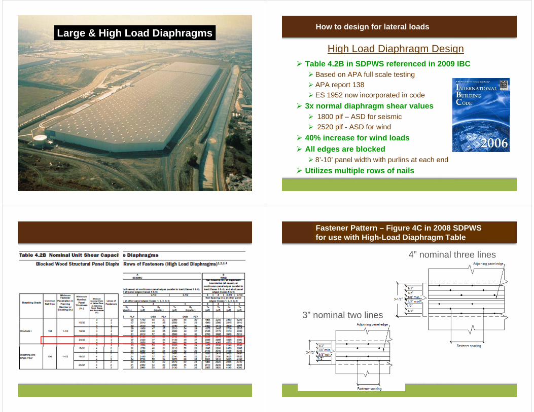
Continuous Girder Ties (E-W)
Continuity Ties
Typical Sub-diaphragm
192’
48’ 48’ 48’48’
EA B C D
192’
Continuous Girder Ties (E-W)
976 plf6,940 lbs
69,400 lbs
f
1,734x18/24=976 plf
Subdiaphragm
40'
,734
plf
(Case 2 E-W direction)1
69,400 lbs
6,940 lbs 976 plf
32'
Continuous Girder Ties (E-W)
A l d i t f d i t th i d f th As load is transferred into the girder from the subdiaphragm, the axial load in the girder increase from 6,940 lb to 69,400 lb, ,
The girder-to-girder connection must resist 69,400 lb
976 x 32 = 27,360,
976 x 32 = 27,360
69,400 lb6,940 lb
9 6 3 ,360
6,940 lb69,400 lb
,
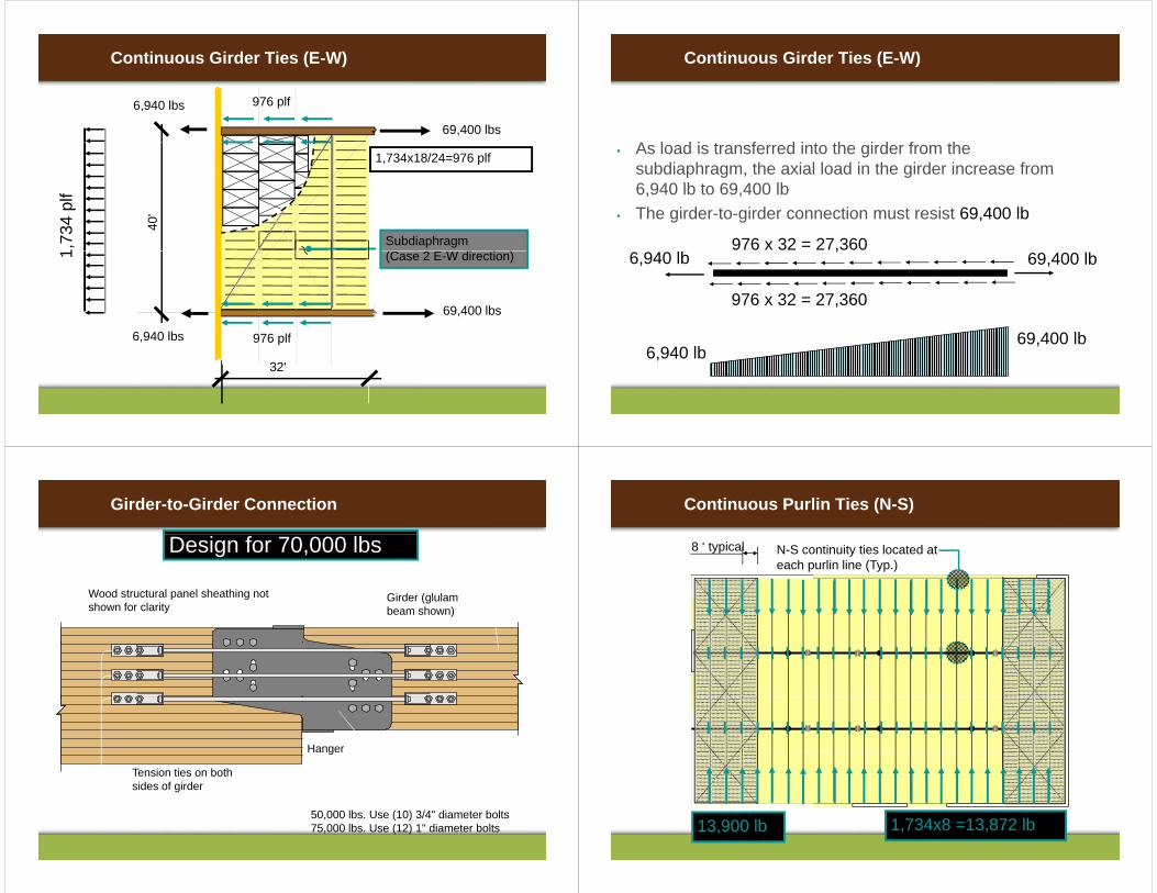
Girder-to-Girder Connection
Design for 70,000 lbs
Girder (glulam beam shown)
Wood structural panel sheathing not shown for clarity
Hanger
Tension ties on both sides of girder
Hanger
50,000 lbs. Use (10) 3/4" diameter bolts75,000 lbs. Use (12) 1" diameter bolts
Continuous Purlin Ties (N-S)
8 ‘ typical N-S continuity ties located at each purlin line (Typ.)
13,900 lb 1,734x8 =13,872 lb
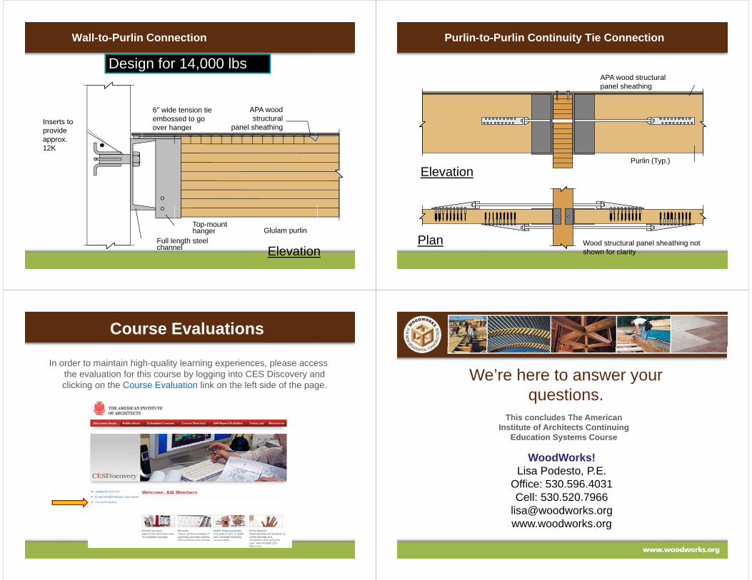
Wall-to-Purlin Connection
Design for 14,000 lbs
Inserts to 6" wide tension tieembossed to go over hanger
APA wood structural
panel sheathingprovide approx. 12K
over hanger panel sheathing
Top-mounthanger Glulam purling
Full length steel channel
p
Elevation
Purlin-to-Purlin Continuity Tie Connection
APA wood structural panel sheathing
Purlin (Typ.)Purlin (Typ.)
Elevation
Wood structural panel sheathing not shown for clarity
Plan
Course Evaluations
In order to maintain high-quality learning experiences, please access the evaluation for this course by logging into CES Discovery and li ki th C E l ti li k th l ft id f thclicking on the Course Evaluation link on the left side of the page.
We’re here to answer your yquestions.
This concludes The AmericanThis concludes The American Institute of Architects Continuing
Education Systems Course
WoodWorks!Lisa Podesto, P.E.
Office: 530.596.4031Cell: 530.520.7966
[email protected] woodworks orgwww.woodworks.org