The Ultra-Wideband RF MEMS Single-Pole-Four- Throw...
2
The Ultra-Wideband RF MEMS Single-Pole-Four- Throw Switch Jin Lin Nanjing Research Institute of Electronics Technology, Nanjing, Jiangsu, China Abstract - This paper researches an ultra-wideband RF MEMS Single–Pole-Four-Throw (SP4T) switch with four shunt-configured, resistive-contact, MEMS cantilever switches. Detailed design and synthesis procedure are provided and the proposed SP4T switch is implemented. The simulated and measured results, where an excellent agreement is obtained, show that an insertion loss is less than 0.8dB and the return loss of every route is better than 24 dB and a minimum isolation is less than 40 dB over the entire band of 1-5GHz. This SP4T switch is actuated by a DC-voltage of 35-45 volts with little current. Index Terms —single-pole-four-throw (SP4T) switch, RF MEMS cantilever switch, microwave printed circuit board technology. 1. Introduction Nowadays, ultra-wideband technology has been getting popular for the high-speed wireless system. As one of the essential components in ultra-wideband system, the switch device using RF MEMS technology is the most attractive part than PIN or field-effect transistor diode switches. MEMS switch devices provide better performance than the conventional semi-conductor technology in terms of low loss, high isolation, (flat) delay and (small) size. Therefore, RF MEMS switch has increasingly been paid more attention. Since 1997, the first RF MEMS cantilever-switch was researched as in [1], more and more researchers have focused on wideband MEMS application technologies, such as broadband phased-array antenna, reconfigurable switch- network and broadband devices, instead of RF MEMS switch itself. Because ultra-wideband technology not only improves system performance but also reduce the cost of radar system. We found that RF MEMS switch in monitoring system can develop its advantage and has a pleasant prospect. MEMS switch can be successfully applied in the broadband radar system, double-frequency- band radar and so on. In recent years, numerous research efforts of RF MEMS single-pole-single-throw switch have been reported as in [2]-[3]. After them, Schauwecker proposed Single-Pole- Double-Throw switch as in [4] and Farinelli reported RF- MEMS SPDT switch on silicon substrate as in [5]. However, few MEMS single-pole-multi-throw switch have been presented in the literature. In 2004, Hamad proposed a wideband SP3T RF MEMS switch as in [6]. In 2003, Daneshmand gave the fabrication and modeling of an SP3T RF MEMS switch as in [7]. In this paper, we presented the design and fabrication of MEMS single-pole-four-throw (SP4T) switch. With the accurate model of MEMS switch and simulation in ANSOFT, the measured results agree with the simulated results well. This paper presented the design techniques, circuit fabrication, simulation method, simulated switching performance and experimental results. 2. The design of RF MEMS switch (1) The theory of MEMS SP4T switch The circuit of MEMS SP4T switch is shown in Fig.1. The input or output ports are 50ohm micro-strip lines. First, in order to match the input impedance which including four shunt-configured capacitances of MEMS switches, Port 1 connects a series inductance which is 150um-width and 1mm-length. Next, the line of port1 is divided into three branches. The middle branch connects a cross-shaped tie and is divided into two ones. So the matched four outputs of SP4T switch are realized. In fact, each branch is high impedance line. Thirdly, each of four routes has a MEMS cantilever switch in series its transmission line. At last we simulate it. Fig. 1. The photograph of the MEMS SP4T switch. Fig.2. The photograph and theoretical illustrate of the MEMS cantilever switch (2) The design of RF MEMS switch The most important component in SP4T switch is MEMS cantilever switch. Fig.2 shows the photograph and principle of the MEMS cantilever switch. The size of MEMS switch is 1mm×1.1mm×0.4mm. When the voltage between up and down electrodes is over the valve-voltage of MEMS switch, the cantilever is pulled down to the micro-strip metal line and the branch is in “ON” state. Whereas, if there is no Proceedings of ISAP2016, Okinawa, Japan Copyright ©2016 by IEICE POS1-90 464
Transcript of The Ultra-Wideband RF MEMS Single-Pole-Four- Throw...

The Ultra-Wideband RF MEMS Single-Pole-Four-Throw Switch
Jin Lin
Nanjing Research Institute of Electronics Technology, Nanjing, Jiangsu, China
Abstract - This paper researches an ultra-wideband RF MEMS Single–Pole-Four-Throw (SP4T) switch with four shunt-configured, resistive-contact, MEMS cantilever switches. Detailed design and synthesis procedure are provided and the proposed SP4T switch is implemented. The simulated and measured results, where an excellent agreement is obtained, show that an insertion loss is less than 0.8dB and the return loss of every route is better than 24 dB and a minimum isolation is less than 40 dB over the entire band of 1-5GHz. This SP4T switch is actuated by a DC-voltage of 35-45 volts with little current.
Index Terms —single-pole-four-throw (SP4T) switch, RF MEMS cantilever switch, microwave printed circuit board technology.
1. Introduction
Nowadays, ultra-wideband technology has been getting popular for the high-speed wireless system. As one of the essential components in ultra-wideband system, the switch device using RF MEMS technology is the most attractive part than PIN or field-effect transistor diode switches. MEMS switch devices provide better performance than the conventional semi-conductor technology in terms of low loss, high isolation, (flat) delay and (small) size. Therefore, RF MEMS switch has increasingly been paid more attention.
Since 1997, the first RF MEMS cantilever-switch was researched as in [1], more and more researchers have focused on wideband MEMS application technologies, such as broadband phased-array antenna, reconfigurable switch-network and broadband devices, instead of RF MEMS switch itself. Because ultra-wideband technology not only improves system performance but also reduce the cost of radar system. We found that RF MEMS switch in monitoring system can develop its advantage and has a pleasant prospect. MEMS switch can be successfully applied in the broadband radar system, double-frequency-band radar and so on.
In recent years, numerous research efforts of RF MEMS single-pole-single-throw switch have been reported as in [2]-[3]. After them, Schauwecker proposed Single-Pole-Double-Throw switch as in [4] and Farinelli reported RF-MEMS SPDT switch on silicon substrate as in [5]. However, few MEMS single-pole-multi-throw switch have been presented in the literature. In 2004, Hamad proposed a wideband SP3T RF MEMS switch as in [6]. In 2003, Daneshmand gave the fabrication and modeling of an SP3T RF MEMS switch as in [7]. In this paper, we presented the
design and fabrication of MEMS single-pole-four-throw (SP4T) switch. With the accurate model of MEMS switch and simulation in ANSOFT, the measured results agree with the simulated results well. This paper presented the design techniques, circuit fabrication, simulation method, simulated switching performance and experimental results.
2. The design of RF MEMS switch
(1) The theory of MEMS SP4T switch The circuit of MEMS SP4T switch is shown in Fig.1.
The input or output ports are 50ohm micro-strip lines. First, in order to match the input impedance which including four shunt-configured capacitances of MEMS switches, Port 1 connects a series inductance which is 150um-width and 1mm-length. Next, the line of port1 is divided into three branches. The middle branch connects a cross-shaped tie and is divided into two ones. So the matched four outputs of SP4T switch are realized. In fact, each branch is high impedance line. Thirdly, each of four routes has a MEMS cantilever switch in series its transmission line. At last we simulate it.
Fig. 1. The photograph of the MEMS SP4T switch.
Fig.2. The photograph and theoretical illustrate of the MEMS cantilever switch
(2) The design of RF MEMS switch The most important component in SP4T switch is MEMS
cantilever switch. Fig.2 shows the photograph and principle of the MEMS cantilever switch. The size of MEMS switch is 1mm×1.1mm×0.4mm. When the voltage between up and down electrodes is over the valve-voltage of MEMS switch, the cantilever is pulled down to the micro-strip metal line and the branch is in “ON” state. Whereas, if there is no
Proceedings of ISAP2016, Okinawa, Japan
Copyright ©2016 by IEICE
POS1-90
464
voltage between electrodes, the cantilever is hung in the air and the switch is in “OFF” state and the branch is closed.
(3) The simulation of MEMS SP4T switch Fig.3 shows the simulation model and circuit of the
MEMS SP4T switch. We analyze one of four branches. When the MEMS switch St1 is on “ON” state and switches (St2-St4) are all on “OFF” state, the RF signal inputs in the port2 and the others are closed. In the meantime, Port2, port3, port4, and port5 are all isolated. We try it one by one and synthesize the entire circuit.
Fig.3 The schematic of MEMS SP4T switch The simulation module of MEMS cantilever switch is the
most difficult to us in the design. We haven’t known the accurate feature of MEMS switch. Maybe we’ll have its accurate simulation model through a mass of application research. That’s the aim of our work. In order to gain accurate design, we first test the S-parameters of MEMS cantilever switch using a probe-tester. But the precondition is MEMS switch is regarded as two-port network. We obtain two groups of S-parameters for the “ON” or “OFF” states before simulating. Then we simulate optimize SP4T device with the software (ANSOFT). The simulated results are shown in Fig.4.
Fig.4 The simulation results of MEMS SP4T switch
Fig.5 The measured insertion loss and VSWR of SP4T
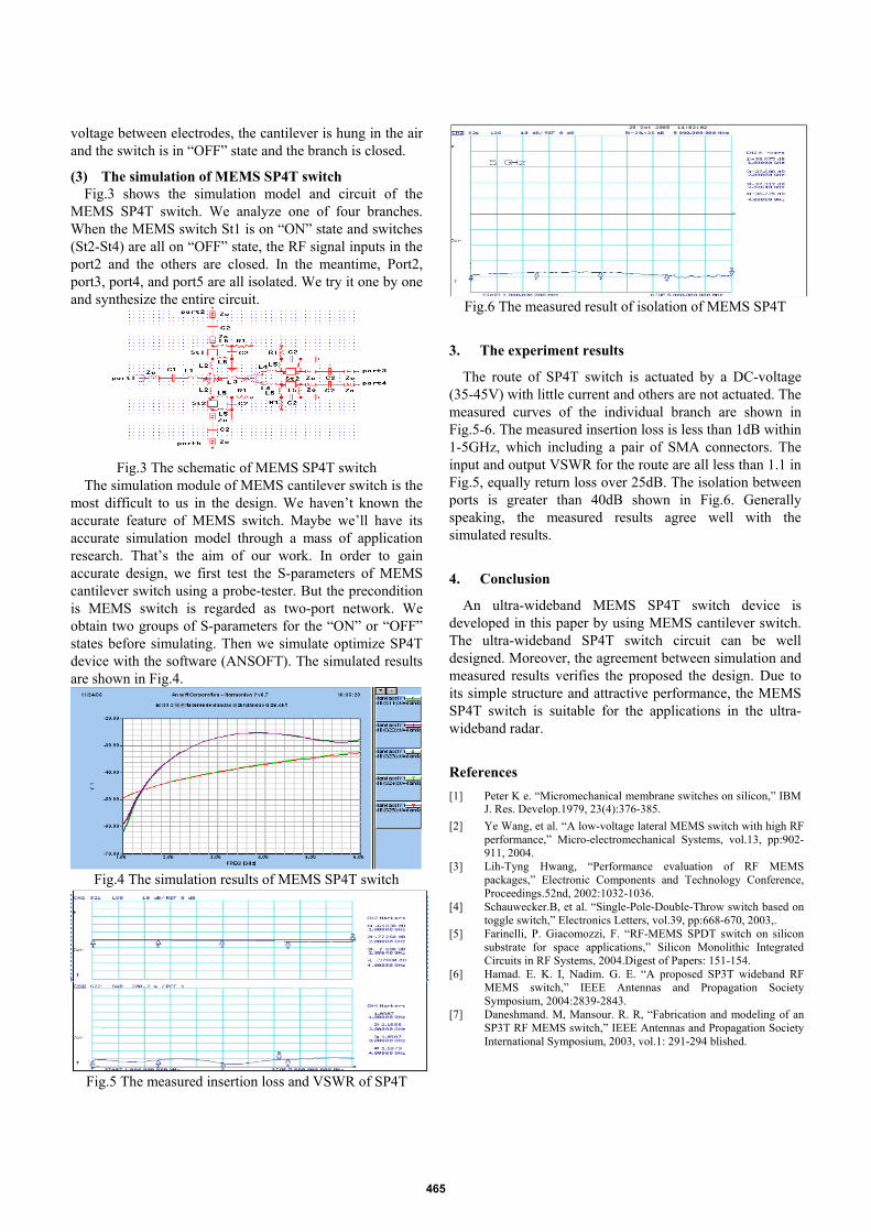
Fig.6 The measured result of isolation of MEMS SP4T
3. The experiment results
The route of SP4T switch is actuated by a DC-voltage (35-45V) with little current and others are not actuated. The measured curves of the individual branch are shown in Fig.5-6. The measured insertion loss is less than 1dB within 1-5GHz, which including a pair of SMA connectors. The input and output VSWR for the route are all less than 1.1 in Fig.5, equally return loss over 25dB. The isolation between ports is greater than 40dB shown in Fig.6. Generally speaking, the measured results agree well with the simulated results.
4. Conclusion
An ultra-wideband MEMS SP4T switch device is developed in this paper by using MEMS cantilever switch. The ultra-wideband SP4T switch circuit can be well designed. Moreover, the agreement between simulation and measured results verifies the proposed the design. Due to its simple structure and attractive performance, the MEMS SP4T switch is suitable for the applications in the ultra-wideband radar.
References
[1] Peter K e. “Micromechanical membrane switches on silicon,” IBM J. Res. Develop.1979, 23(4):376-385.
[2] Ye Wang, et al. “A low-voltage lateral MEMS switch with high RF performance,” Micro-electromechanical Systems, vol.13, pp:902-911, 2004.
[3] Lih-Tyng Hwang, “Performance evaluation of RF MEMS packages,” Electronic Components and Technology Conference, Proceedings.52nd, 2002:1032-1036.
[4] Schauwecker.B, et al. “Single-Pole-Double-Throw switch based on toggle switch,” Electronics Letters, vol.39, pp:668-670, 2003,.
[5] Farinelli, P. Giacomozzi, F. “RF-MEMS SPDT switch on silicon substrate for space applications,” Silicon Monolithic Integrated Circuits in RF Systems, 2004.Digest of Papers: 151-154.
[6] Hamad. E. K. I, Nadim. G. E. “A proposed SP3T wideband RF MEMS switch,” IEEE Antennas and Propagation Society Symposium, 2004:2839-2843.
[7] Daneshmand. M, Mansour. R. R, “Fabrication and modeling of an SP3T RF MEMS switch,” IEEE Antennas and Propagation Society International Symposium, 2003, vol.1: 291-294 blished.
465