THE TRAVELING-WAVE V-ANTENNA - NASA · A traveling-wave V-antenna consists of two identical arms...
18
7 - THE TRAVELING-WAVE V-ANTENNA Scient if ic Report No. 4 GPO PRICE $y CFSTI PRICE(S) $ - ff 653 July 65 BY Keigo lizuka and Ronold W.f? King March 1965 NATIONAL AERONAUTICS AND SPACE ADMINISTRATION Prepared under Grant No. NsG 579 Gordon McKay laboratory, Harvard University Cambridge, Massachusetts (ACCESSION NUM 1 9f7 I tCO#El I I . r https://ntrs.nasa.gov/search.jsp?R=19670006193 2020-04-02T02:36:48+00:00Z
Transcript of THE TRAVELING-WAVE V-ANTENNA - NASA · A traveling-wave V-antenna consists of two identical arms...
7 -
THE TRAVELING-WAVE V-ANTENNA
Scient i f ic Report No. 4
GPO PRICE $y
CFSTI PRICE(S) $-
ff 653 July 65 BY
Keigo lizuka and Ronold W.f? King
March 1965
NATIONAL AERONAUTICS AND SPACE ADMINISTRATION
Prepared under Grant No. NsG 579 Gordon McKay laboratory, Harvard University
Cambridge, Massachusetts
(ACCESSION NUM 1 9f7 I tCO#El I
I
.
r
https://ntrs.nasa.gov/search.jsp?R=19670006193 2020-04-02T02:36:48+00:00Z
/ .. - I .
THE TRAVELING-WAVE V-ANTENNA
By Keigo Iizuka and Ronold W . P. King
Scientific Report No. 4
March 1965
Prepared under Grant No. NsG 579 at Gordon Mc Kay Laboratory, Harvard University
Cambridge, Massachusetts
for
. I
NATIONAL AERONAUTICS AND SPACE ADMINISTRATION
I . .
THE TRAVELLNG-WAVE V-ANTENNA
By Keigo Iizuka and Ronold W. P. King
Gordon Mc Kay Laboratory, Harvard University Cambridge, Massachusetts
SUMMARY
An antenna which is a combination of the resonant V-antenna and the traveling-wave dipole antenna was studied both theoretically and experimentally. The universal curves which a r e useful for determining the values of the length of the antenna a rms , apex angle, and loading resistors a r e presented. The theoretical curves for the radiation pattern agree in a general sense with those of experiments. wavelength long traveling-wave V-antenna has a gain 10. 5 times as large as that of a half-wave dipole.
The antenna has a pencibbeam radiation pattern. The two-
INTRODUCTION
A traveling-wave V-antenna is a V-antenna with a set of terminating
The traveling-wave V-antenna is a combination of the resonant V-antenna resis tors near its endsof such value that the current is substantially a traveling wave. described by P . S . Carter (ref. l), et al., in 1931 and in recent books (ref, 2, 3,4), and the traveling-wave dipole antenna studied by Hall& (refs.5), Altshuler (ref. 6), and quite recently by Wu and King (ref. 7).
A linear dipole antenna is characterized principally by a standing wave of current resulting from reflections a t the ends. frequency sensitive. waves by gradually increasing the surface impedance of the wire as the ends were approached. surface impedance of the antenna. maximum nearest the ends of the antenna for the same purpose.
Its impedance is highly Halle/n, and Wu and King suppressed the reflected current
It was achieved either by ohmic or purely reactive changes of the Altshuler placed resistors a t the current
A traveling-wave V-antenna combines the advantages of a V-antenna It is characterized by simplicity in structure, a and a traveling-wave dipole.
broad frequency band, and high directivity, but also by a loss of power in the terminating impedances. complications in the analysis. design procedures.
The absence of cylindrical symmetry leads to This report includes a discussion of theory and
-1-
-2 -
VALUES OF THE LOADING RESETORS FOR TRAVELING-WAVE EXCITATION
Strictly speaking, a pure traveling wave of current can exist only on nonradiating transmission lines that are terminated in their characteristic impedances. However, the current in a properly loaded V-antenna with apex angle A, shown in Fig. 1, can be resolved into a large component which is a pure traveling wave, and a relatively small correction term. traveling-wave part of the current must behave just as i f i t were maintained on a tapered transmission line with a spacing d that is proportional to the distance from the driving point. (or hT away from the end).
It follows that the
This line is terminated in a set of resistors at r = h
In order to answer the question, what lumped resiptance should be selected to minimize the wave reflected from the end, i t is & satisfactory approximation to consider only the large traveling-wave component of the current which may be determined by transmission-line theory. For this purpose, it is convenient to introduce a characteristic impedance, Zc , that varies with the distance from the feeding point. difference between the two arms of the V to the current in a wire - a quasi- stationary approximation. Alternatively, it is defined as the ratio &- (refs.3,
4, 18) where the distributed parameters L and C vary with distance and are calculated in a quasi-stationary manner. case -- = 90°, this approximation is in general agreement with the more precise
analysis by Hallen (ref. 5) (see F ig . 2). (ref. 9) show that the reflected current wave is always minimum when the loading resistance i s near the values obtained with this approximation. of ref. 9.)
It i s defined as the ratio of the scalar potential
It is readily shown that in the special A 2
Moreover, measurements by Duff
(See Fig. 3
The resistors a r e located where the current amplitude is a maximum The value of the current a t this position is in the absence of the resistors.
twice the incident wave, 210. When the resistors a r e inserted, the potential drop Ih. R is established across each. By the compensation theorem this drop may be replaced by a generator with a voltage -Ih' R where Ih is the total current in the resistor a t z = h. The two generators - one in each arm of the V -are in ser ies with the transmission-line impedances looking toward and away from the apex. the length hT- (2n+l) X/4 such that the input impedance is zero, the equivalent transmission-line circuit consist6 of a length of line h with a generator V at z = 0 and a generator -21h' R at z = h. The total current is
If the length hT toward the open end bas
0
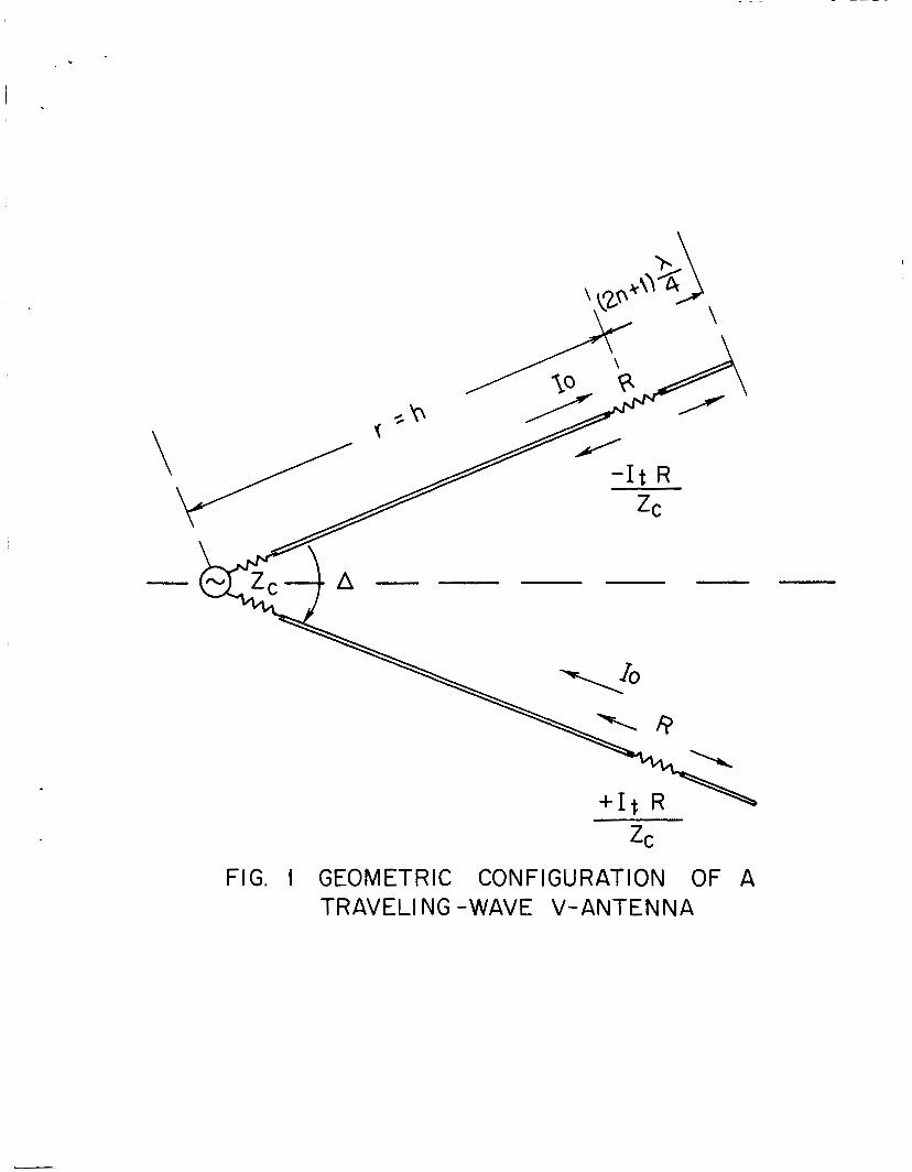
FIG. 1 GEOMETRIC CONFIGURATION OF A TRAVEL1 NG -WAVE V-ANTENNA
. - I
I I I I I I
9- -
I
10 I
8-
RESISTANCE R FOR VARIOUS D BY ALTSH U LER
FOR fi =14
'\i400
~
c W z
- I I 0
E w
- 0 z U c
a w
- c T
W z a
E
- - 0
-1
x r' /
BY H A L L C N - x THICKNESS ANTENNA FOR Till,OOO
- 1 -
0 I I 1 1 I I I
FI
200
100
'ANCE
Z A
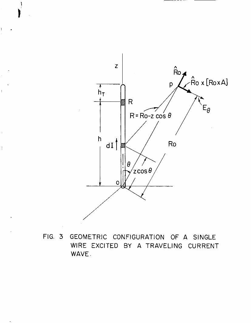
FIG. 3 GEOMETRIC CONFIGURATION OF A SINGLE WIRE EXCITED BY A TRAVELING CURRENT WAVE.
C
- 3-
cos kz - 2 IhR cos kh J - 1 I ( 2 ) = j ZCtankh
If k is determined with z = h, the result is
zC cos kh t j 2 ~ s i f ; l k h
2Rcoskh t jZCs inkh
I
cos kz - j s in I ( z ) =
It follows at once that a traveling wave
V -jkz ze I ( 2 ) = c,
is obtained when
zC R = - . 2
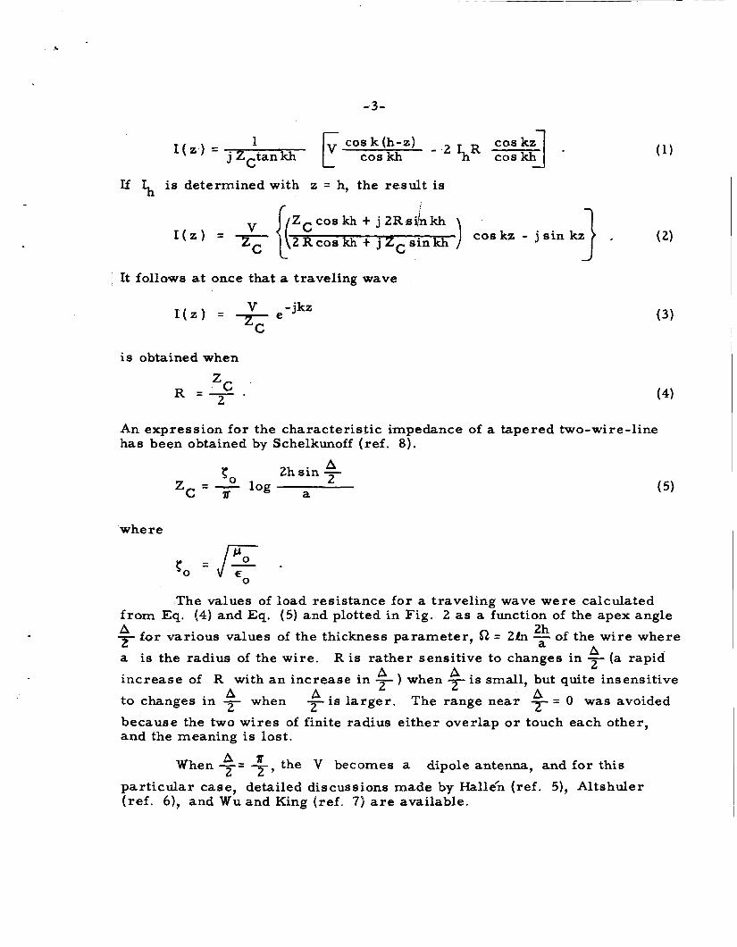
An expression for the characteristic impedance of a tapered two-wire-line has been obtained by Schelkunoff (ref. 8).
(3)
where
The values of from Eq. (4) and Eq. A -€or various values t
A 2 2h sin -
a
(4)
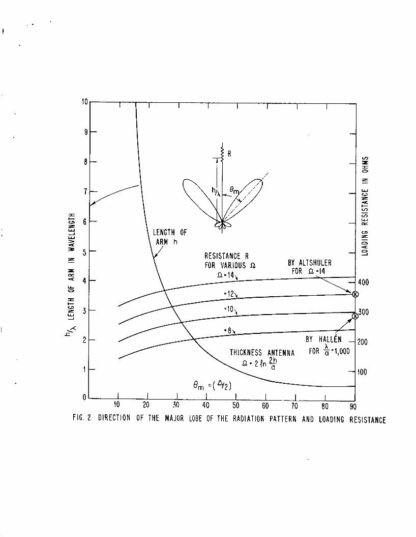
load resistance for a traveling wave were calculated (5) and plotted in Fig. 2 as a function of the apex angle of the thickness parameter, 52 = 21n - of the wi re where 2h
a P a is the radius of the wi re .
increase of R with an increase in ) when is small, but quite insensitive b to changes in - when 2
because the two wi re s of finite radius either overlap o r touch each other, and the meaning is lost.
R is rather sensitive to changes in - (a rapid 2 A A A A ' t i s larger. The range near = 0 was avoided
When 7 - - 7 , ' the V becomes a dipole antenna, and for this
particular case, detailed discussions made by Hallek (ref. 5), Altshuler (ref. 6), and Wu and King (ref. 7) are available.
-4-
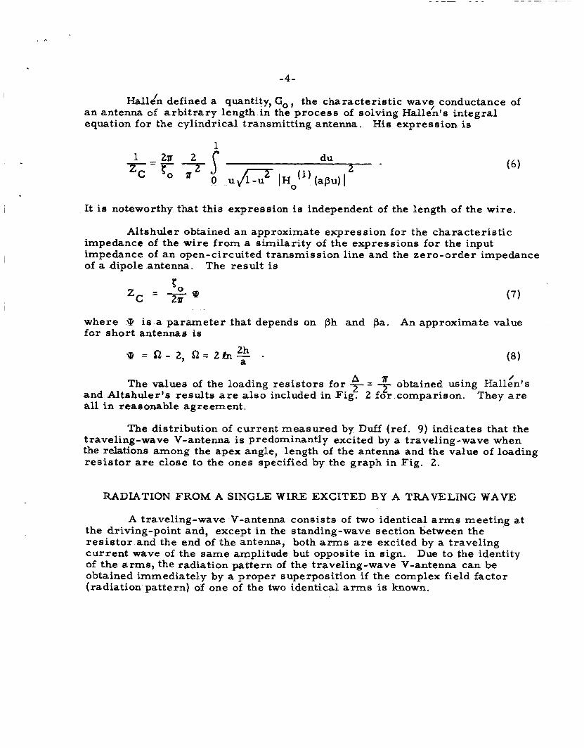
Hall& defined a quantity, Go, the characteristic wave/ conductance of an antenna of arbitrary length in the process of solving Hallen's integral equation for the cylindrical transmitting antenna. His expression is
It is noteworthy that this expression is independent of the length of the wire.
Altshuler obtained an approximate expression for the characteristic impedance of the wire from a similarity of the expressions for the input impedance of an open-circuited transmission line and the zero-order impedance of a dipole antenna. The result is
P
P - zc - - 21i (7)
where iP is a parameter that depends on ph and pa. An approximate value for short antennas is
( 8 ) 2h a p = 52- 2, s1= 2h- -
/ The values of the loading resistors for * = 7 * obtained using Hallen's
They are and Altshuler's results a r e also included in Fig. 2 for comparison. all in reasonable agreement.
The distribution of current measured by Duff (ref. 9) indicates that the traveling-wave V-antenna is predominantly excited by a traveling-wave when the relations among the apex angle, length of the antenna and the value of loading resis tor are close to the ones specified by the graph in Fig. 2.
RADIATION FROM A SINGLE WIRE EXCITED B Y A TRAVELING WAVE
A traveling-wave V-antenna consists of two identical arms meeting a t the driving-point and, except in the standing-wave section between the resis tor and the end of the antenna, both a r m s a r e excited by a traveling current wave of the same amplitude but opposite in sign. of the arms, the radiation pattern of the traveling-wave V-antenna can be obtained immediately by a proper superposition if the complex field factor (radiation pattern) of one of the two identical arms is known.
Due to the identity
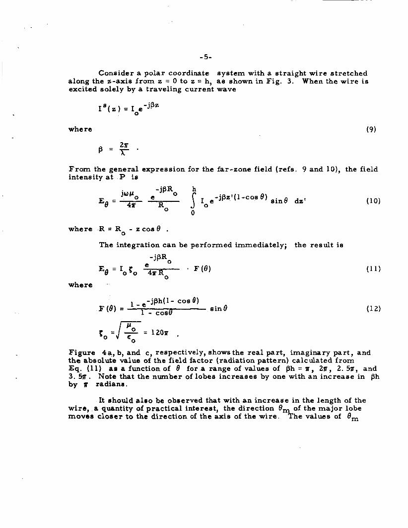
- 5- Consider a polar coordinate system with a straight wire stretched
along the z-axis from z = 0 to z = h, as shown in Fig. 3. When the wire is excited solely by a traveling current wave
where (9)
From the general expression for the far-zone field (refs. 9 and lo) , the field intensity at P is
where R = R - z c o s 8 . 0
The integration can be performed immediately; the result is
- j PRO
*= Ro * W ) e Eo = Iobo
where -
- jph( 1 - cos 0) sin 8 1 - e
1 - case F(6) =
to = / % = 1207l ,
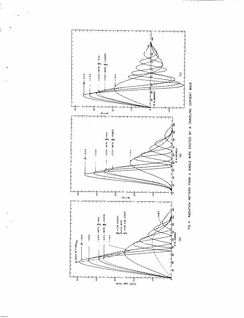
Figure 4a , b, and c, respectively, shows the real part, imaginary par t , and the absolute value of the field factor (radiation pattern) calculated from Eq. (11) a s a function of 8 for a range of values of ph = li, 2u, 2. 5a, and 3. 5jr . by u radians.
Note that the nurnber of lobes increases by one with an increase in ph
It ehould also be observed that with an increase in the length of the wire, a quantity of practical interest, the direction 8, of the major lobe moves cloeer to the direction of the axis of the wire . The values of 8,
- 6 -
can be found by equating the derivative of Calculated values of 8, a r e shown in Fig. 2; em is along the horizontal axis; the length of the wire is along the vertical axis. It is seen from the figure that the rate of decrease in 8, with respect to an increase in ph becomes rapidly smaller as 8, is reduced and 6, can be zero only in the limit of infinite ph. The rate of decrease in 8, is extremely small when ph is larger than 1 2 ~ .
Eo with respect to 6 to zero ~
This information about for a single wire is important for determining the apex angle A of the traveling-wave V-antenna for which the maximum power is radiated in the direction of the y-axis (see Fig. 5). For the optimum value
since,with this apex angle, the direction of the major lobe of the one arm is superimposed on that of the other. traveling-wave V-antenna should be decreased as the length of the a r m s is increased in order to maintain the maximum radiation along the y-axis.
It follows that the apex angle of the
Another interesting fact to be mentioned is that the narrowest beam width D (angle between the first minima of the azimuthal radiation pattern) of the traveling-wave V-antenna obtainable by adjusting the apex angle for a given length and resistor is equal to the apex angle of the antenna, i. e . ,
~ = h o p t 2 m
The width of the major lobe of the antenna increases with either an increase o r decrease in the apex angle from its optimum value.
In the above analysis, the attentuation of the traveling wave along the wire was not taken into consideration. antenna is very long. along the wi re to be used is
This is not necessary unless the When attenuation is included, the distribution of current
The calculated results using Eq. (15) instead of Eq. (9) are compared with those based upon a loss-free w i r e in Fig. 4. The attenuation.constant used in the calculations is that measured by Duff (ref. 9),viz., 0 . 6 dB per wave- length independent of the apex angle. It is seen that the attenuation of the current has little effect on the radiation pattern.
This corresponds to C L / ~ = 0.021 5.
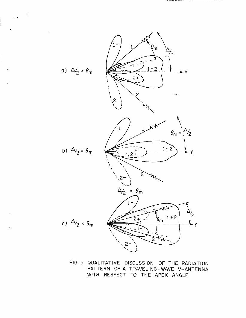
-Y
FIG. 5 QUALITATIVE DISCUSSION OF THE RADIATION PATTERN OF A TRAVELING - WAVE V-ANTENNA WITH RESPECT TO THE APEX ANGLE
-7-
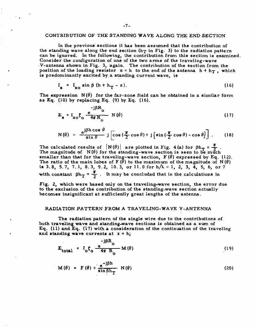
CONTRIBUTION OF THE STANDING WAVE ALONG THE END SECTION
In the previous sections it has been assumed that the contribution of the standing wave along the end section (hT in Fig. 3) to the radiation pattern can be ignored. Consider the configuration of one of the two arms of the traveling-wave V-antenna shown in Fig. 3, again. position of the loading resistor z = h to the end of the antenna h t hT , which is predominantly excited by a standing current wave, is
In the following, the contribution from this section is examined.
The conkribution of the section from the
I = I s i n p (h t hT - z). s so The expression N(e) for the far-zone field can be obtained in a similar form as Eq. (10) by replacing Eq. (9) by Eq. (16).
r U sin ("z cos 8 ) t j [ s i n ( T cos 8 ) - COS e)] . (18)
e N(8) =
'R The calculated results of IN ( 8 ) I are plotted in Fig. 4 (a) for @hT = 7 . The magnitude of N(8) for the standing-wave section is seen to be much smaller than that for the travelin -wave section, F ( 8 ) expressed by Eq. (12).
i s 3 . 8 , 5.7, 7.1, 8.3, 9.2, 10.3, o r l l . O f o r h / k = l , 2, 3, 4, 5, 6, o r 7
with constant phT = f . It m a y be concluded that in the calculations in
The ratio of the main lobes of F ( B ) to the maximum of the magnitude of N(e)
Fig. 2, which were based only on the traveling-wave section, the error due to the exclusion of the contribution of the standing-wave section actually becomes insignificant at sufficiently great lengths of the antenna.
RADIATION PATTERN FROM A TRAVELING-WAVE V-ANTENNA
The radiation pattern of the single wi re due to the contributions of both traveling wave and standingaave sections is obtained as a sum of Eq. (1 1) and Eq. (17) with a consideration of the continuation of the traveling and standing wave currents at z = h;
-jW0 M ( 6 ) (19)
e = roto Etotal 4a Ro
-8-
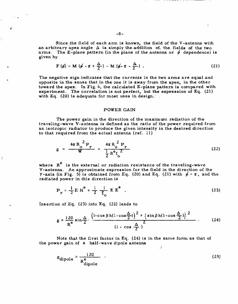
Since the field of each arm is known, the field of the V-antenna with
The E-plane pattern (in the plane of the antenna o r jd dependence) is an arbi t rary apex angle A is simply the addition of, the fields of the two arms. given by
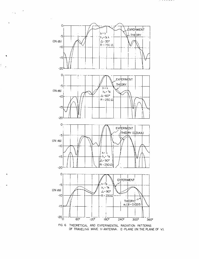
The negative sign indicates that the currents in the two arms are equal and opposite in the sense that in the one i t is away from the apex, in the other toward the apex. experiment. The correlation is not perfect, but the expreseion of Eq. (21) with Eq. (20) is adequate for most uses in design.
In Fig. 6, the calculated E-plane pattern is compared with
POWER GAIN
The power gain in the direction of the maximum radiation of the traveling-wave V-antenna is defined as the ratio of the power required from an isotropic radiator to produce the given intensity in the desired direction to that required from the actual antenna (ref. 11)
4mR0' Pr - - 4u RoL Pr
w i R e I g =
0
where Re is the external or radiation resistance of the traveling-wave V-antenna. Y-axis (in Fig. 5) is obtained from Eq. (20) and Eq. (21) with jd = r , and the radiated power in this direction is
An approximate expression for the field in the direction of the
1 * 1 1 * P =-EH =--EE , (50
r 2
Insertion of Eq. (23) into Eq. (22) leads to
Note that the f i rs t factor in Eq. (24) is in the same form as that of the power gain of a half-wave dipole antenna
- 120 - gdipole e
Rdipole
8
-5
t (IN db)
-10 I
C
-5
(IN db)
-10
-I 5
-20
.
(IN
FIG. 6 THEORETICAL AND EXPERIMENTAL RADIATION PATTERNS OF TRAVELING WAVE V-ANTENNA. E-PLANE (IN THE PLANE OF V)
-9-
Hence, the second factor in Eq. (25) determines how much better the directivity of a traveling-wave V-antenna is than that of a half-wave dipole, when the radiation resistances a re the same for both antennas. Taking the traveling-wave V-antenna with h = 2h (whose apex angle 7 is 36O from Fig. 2) for example, the gain is
A
g = 1 0 . 5 . g dipole *
ACKNOWLEDGMENT
Numerous helpful discussions with Trilochan Padhi a r e gratefully acknowledged. some of the expressions for the field pattern.
W e are also indebted to Bob Duff for independently suggesting
REFERENCES
1. P. S. Carter, C. W. Hansell, and N. E. Lindenbald, "Development of Directive Transmitting Antennas by RCA Communications, Inc., Proc. IRE l9, 1773-1842 (October 1931).
P res s , Cambridge, Massachusetts, 1956, pp. 381-397, 686 and 691. 2. R. W. P. King, The Theory of Linear Antennas, Harvard University
3. S. A. Schelkunoff, Advanced Antenna Theory, John Wiley and Sons, Inc., New York, 3952, pp. 97-109.
4. S. A. Schelkunoff and H. T. Friis, Antennas, John Wiley and Sons, Inc., New York, 1952, pp. 109-110, 424-427, 499-502, 260 and 193.
5. E. Hallen, Electromagnetic Theory, John Wiley and Sons, Inc., New York, 1962, pp. 501-504, 444-456.
6 . E. E. APtschuler, ''The Traveling-Wave Linear Antenna, Trans. IRE on Antennas and Propagation - 9 AP-9 324-329 (July 1961).
7. T. T. Wu and R. W. P. King, !'The Cylindrical Antenna with Nonreflecting Resistive Loading, '1 submitted to IEEE Trans. on Antennas and Propagation.
8. S. A. Schelkunsff, Electromametic Waves, Van Nostrand Co., Inc., New York, 1943, p. 293.
.J
-10-
9. B. M. Duff, "The Resistively-Loaded V-Antenna Current Distribution, Impedance, and Terminal- Zone Correction, Radiation Field, sf NASA Scientific Report No. 3, Harvard University, Cambridge, Massachusetts , October 1964.
10. R. W. P. King, Electromagnetic Engineering, McGraw-Hill Book C Q . , Inc., New York, 1945, pp. 268-275; the same pages of the Dover edition published in 1963.
11. S. Ram0 and J. Whinnery, Field and Waves in Modern Radio, John Wiley and Sone, Inc., New York, and Hall, Ltd., London, 1953, pp. 503-504.