The Stress-strain Behavior of Polymer-nanotube Composites ... · NASA/CR-2002-211953 ICASE Report...
19
NASA/CR-2002-211953 ICASE Report No. 2002-41 The Stress-strain Behavior of Polymer-nanotube Composites from Molecular Dynamics Simulations S.J.V. FrankIand, V.M. Harik, and G.M. Odegard ICASE, Hampton, Virginia D. W. Brenner North Carolina State University, Raleigh, North Carolina T.S. Gates NASA Langley Research Center, Hampton, Virginia November 2002 https://ntrs.nasa.gov/search.jsp?R=20030004708 2018-07-26T18:49:02+00:00Z
Transcript of The Stress-strain Behavior of Polymer-nanotube Composites ... · NASA/CR-2002-211953 ICASE Report...

NASA/CR-2002-211953
ICASE Report No. 2002-41
The Stress-strain Behavior of Polymer-nanotube
Composites from Molecular Dynamics Simulations
S.J.V. FrankIand, V.M. Harik, and G.M. Odegard
ICASE, Hampton, Virginia
D. W. Brenner
North Carolina State University, Raleigh, North Carolina
T.S. Gates
NASA Langley Research Center, Hampton, Virginia
November 2002
https://ntrs.nasa.gov/search.jsp?R=20030004708 2018-07-26T18:49:02+00:00Z

The NASA STI Program Office... in Profile
Since its founding, NASA has been dedicated
to the advancement of aeronautics and spacescience. The NASA Scientific and Technical
Information (STI) Program Office plays a key
part in helping NASA maintain this
important role.
The NASA STI Program Office is operated by
Langley Research Center, the lead center forNASA's scientific and technical information.
The NASA STI Program Office provides
access to the NASA STI Database, the
largest collection of aeronautical and space
science STI in the world. The Program Officeis also NASA's institutional mechanism for
disseminating the results of its research and
development activities. These results are
published by NASA in the NASA STI Report
Series, which includes the following report
types:
TECHNICAL PUBLICATION. Reports of
completed research or a major significant
phase of research that present the results
of NASA programs and include extensive
data or theoretical analysis. Includes
compilations of significant scientific andtechnical data and information deemed
to be of continuing reference value. NASA's
counterpart of peer-reviewed formal
professional papers, but having less
stringent limitations on manuscript
length and extent of graphic
presentations.
TECHNICAL MEMORANDUM.
Scientific and technical findings that are
preliminary or of specialized interest,
e.g., quick release reports, working
papers, and bibliographies that containminimal annotation. Does not contain
extensive analysis.
CONTRACTOR REPORT. Scientific and
technical findings by NASA-sponsored
contractors and grantees.
CONFERENCE PUBLICATIONS.
Collected papers from scientific and
technical conferences, symposia,
seminars, or other meetings sponsored or
cosponsored by NASA.
SPECIAL PUBLICATION. Scientific,
technical, or historical information from
NASA programs, projects, and missions,
often concerned with subjects having
substantial public interest.
TECHNICAL TRANSLATION. English-
language translations of foreign scientific
and technical material pertinent toNASA's mission.
Specialized services that complement the
STI Program Office's diverse offerings include
creating custom thesauri, building customized
data bases, organizing and publishing
research results.., even providing videos.
For more information about the NASA STI
Program Office, see the following:
• Access the NASA STI Program Home
Page at http://www.sti.nasa.gov
• Email your question via the Internet to
help @ sti.nasa.gov
• Fax your question to the NASA STI
Help Desk at (301) 621-0134
• Telephone the NASA STI Help Desk at
(301) 621-0390
Write to:
NASA STI Help Desk
NASA Center for AeroSpace Information7121 Standard Drive
Hanover, MD 21076-1320

NASA/CR-2002-211953
ICASE Report No. 2002-41
The Stress-strain Behavior of Polymer-nanotube
Composites from Molecular Dynamics Simulations
S.J.V. Frankland, V.M. Harik, and G.M. Odegard
ICASE, Hampton, Virginia
D. W. Brenner
North Carolina State University, Raleigh, North Carolina
T.S. Gates
NASA Langley Research Center, Hampton, Virginia
ICASE
NASA Langley Research Center
Hampton, Virginia
Operated by Universities Space Research Association
Prepared for Langley Research Centerunder Contract NAS 1-97046
November 2002

Available from the following:
NASA Center for AeroSpace Information (CASI)
7121 Standard Drive
Hanover, MI) 21076-1320
(301) 621-0390
National Technical Information Service (NTIS)
5285 Port Royal Road
Springfield, VA 22161-2171
(703) 487-4650

THE STRESS-STRAIN BEHAVIOR OF POLYMER-NANOTUBE COMPOSITES
FROM MOLECULAR DYNAMICS SIMULATION
S. J. V. FRANKLAND 1'2, V. M. HARIK la'_, G. M. ODEGARD 1'2, D. W. BRENNER 4, AND T. S. GATES s
Abstract. Stress-strata curves of polymer-carbon nanotube composites are derived from
molecular dynamics simulations of a single-walled carbon nanotube embedded in polyethylene. A
comparison is made between the response to mechanical loading of a composite with a long, continuous
nanotube (replicated via periodic boundary conditions) and the response of a composite with a short,
discontinuous nanotube. Both composites are mechanically loaded in the direction of and transverse to
the NT axis. The long-nanotube composite shows an increase in the stiffness relative to the polymer and
behaves anisotropically under the different loading conditions. The short-nanotube composite shows no
enhancement relative to the polymer, most probably because of its low aspect ratio. The stress-strain
curves are compared with rule-of-mixtures predictions.
slxainKey Words. carbon nanotubes, molecular dynamics simulation, polymer composites, stress-
Subject Classification. Smactures and Materials
Nomenclature
AI, A2, A3
Ace_l
E
E_
A'r
fr.
F/._
hvdw
M _
S
U
U_
r
Rt,_r
U
V
gl
- Constants for torsional potential _b(0)
- Cross-sectional area of unit cell_ Tr_f_l 4*_t_-n_l _normr ,_4" _r,14A
- Total internal of atom oc
- Nanotube volume fraction
- Polymer matrix volume fraction
-/-component of the force between atoms c_and [3
- Average van der Waals separation between nanotube and matrix- Mass of atom a
- Denotes constant entropy
- Kinetic energy of atom oc
- Potential energy of atom ot
- Magnitude of separation distance between a pair of atoms
-j-component of the separation distance of atoms oc and 13- Radius ofnanotube
- Potential energy between a pair of atoms- Volume of solid
- Atomic volume of atom ot
- Longitudinal elastic modulus of composite
ICASE, M/S 132C, NASA Langley Research Center, Hampton, VA 23681.
2 This research was partially supported by the National Aeronautics and Space Administration under NASA Contract No.
NAS1-97046 while S. J. V. Frankland, V. M. Harik, and G. M. Odegard were in residence at ICASE, NASA Langley Research
Center, Hampton, VA 23681.
"=Current address: Swales Aerospace, M/S I90, NASA Langley Research Center, Hampton, VA 23681.
4 Department of Materials Science and Engineering, North Carolina State University, Raleigh, NC 27695.
5 Mechanics and Durability Branch, NASA Langley Research Center, Hampton, VA 23681.

Y1NT
Y2
Ym
_u
£LJ
0(o)
_(r)V c_
Vcti
crO.
O-LJ
- Elastic modulus of the nanotube
- Transverse elastic modulus of composite- Effective transverse elastic modulus of nanotube
- Elastic modulus of the polymer matrix
- Strain tensor
- Potential well depth
- Torsional potential for angle O
- Potential energy at the atom o_for separation distance r
- Magnitude of the velocity of atom oc
-/-component Of the velocity of atom o_
- Torsional angle around the CH2-CH2 bond- Stress tensor
- Van der Waals separation distance
1. Introduction. In the last few years, single-walled carbon nanotube-polymer composites
have generated considerable interest in the materials research community because of their potential for
large increases in strength and stiffness when compared to typical carbon-fiber-reinforced polymer
composites. Even though some nanotube composite materials have been characterized experimentally [1-
12], the development of these materials can be greatly facilitated by using computational methods that
allow for parametric studies of the influence of material and geometry. Molecular dynamics (MD)
simulations can predict the effect of mechanical loading on specific regions of polymer-nanotube (NT)
composites. In this work, stress-strain curves are generated from molecular dynamics simulations of
po!3_ner-.NT composites to explore the nano-s_acV_al effects on the overall mechmnica! prope_ies of
polymer-NT composites.
Various aspects of the mechanical reinforcement of polymers by carbon nanotubes (ART) have
been addressed computationally. One example of recent work is an equivalent-continuum modeling
method that was used to predict the elastic properties of two single-walled polyimide-NT composites for
various NT volume fractions, lengths, and orientations [13]. At the continuum level, finite element
analysis has been used to predict the macroscale effects of'wavy' or not straight NTs [14,15]. Molecular
statics simulations of the transverse mechanical properties of NT bundles have shown the strong cohesion
of NTs compared to a graphite-epoxy matrix [16]. Mechanical properties of NT yarns have been
predicted from the elastic constants of NT bundles [17]. Molecular modeling has predicted the adhesion
between a NT and various polymer matrices [18]. Molecular dynamics simulations have predicted that
the polymer-NT interface can be reinforced by covalently bonding the NT to the polymer matrix [19].
Another feature of the mechanical behavior ofpolymer-NT composites that can be modeled is the
stress-strain relation. The stress-strain relationship provides the overall mechanical response of NT-
polymer composites when subjected to mechanical loading. In the present work, stress-strain curves of
two polyethylene-NT composites are generated with molecular dynamics (MD) simulations [20]. The
effects of both the anisotropy of the composites when subjected to different loading conditions and of the
length of the NT are explored. The first composite contains a long (infinitely long) NT, and the second
composite, a short NT. Details of the composite structure and MD simulations are given in Section 2.
Stress-strain curves are presented for longitudinal and transverse loading conditions of each composite
(Section 5). A detailed description of the computation of stress from molecular force fields in Section 3.
Comparison is made of the simulated stress-strain curves with the rule of mixtures. The relevant
equations are in Section 4.

2. Molecular Dynamics Simulations. The unidirectional NT-polymer composites contain
symmetrically placed long or short NTs as shown in Figure 1. The dashed boxes in Figure 1 enclose a
representative volume element that is simulated by MD. In each composite, the NTs are sufficiently
separated by polymer to prevent direct NT-WI" interactions. The NT composite in Figure l(a) contains a
periodically replicated (10,10) NT which spans the length of the simulation cell. (The (n,m) notation
refers to the chiral vector of the NT in terms of the primitive in-plane lattice vectors of a graphene sheet
[21].) In this composite, the iXrf is embedded in an amorphous polyethylene (PE) matrix, which is
represented by beads of united atom -CH2- units. Specifically, the PE matrix has eight chains of 1095 -
CH2- units. The short-fiber composite, shown in Figure t(5), contains a 6-nm capped (10,10) NT which
is approximately half the length of the simulation cell. The NT caps each consist of one half of a C240
molecule. In this composite, the amorphous PE matrix contains eight chains of 1420 -CH2- units. The
overall dimensions for the unit-cell, or minimum image, of each composite in the MD simulation are
approximately 5xSx10 nm. Periodic boundary conditions were used to replicate the cell in all three
dimensions. For comparison to the NT/PE composites, an equivalent-sized block of amorphous PE
without a NT was also simulated. For each structure, a PE density of 0.71 g/cm 3 was used.
In the MD simulation, the van der Waals interfacial interaction between the polymer and the NT
was modeled with the Lennard-Jones potential [22],
(2.1) U = 4E:j cYI2L r 1_ r 6
where U is the potential energy between a pair of atoms, r is the separation distance between the pair of
atoms, eza is the potential well depth, and cr_ is the van der Waals separation distance. For the interaction
between the carbon atoms of the NT and the polsn-ner -CH2- units, the potential was parametrized with
S/j=(I A/IQ9 kT/mnl nncl CrLa_-(_ 2Rgq _rn r99 9"_] ThP. ]D'_' ."h'_l_e xxr_'r_ eqv_l,l_f_A '_xr_tIa _ molecular-
mechanics force field adapted from Reference 23. Specifically, the -CH2- units of the PE chains were
separated by bond lengths of 0.153 nm by using the SHAKE algorithm, a constraint dynamics method
which constrains the bond length within a user-defined tolerance [22]. Angle bending forces were
modeled with a harmonic valence-angle potential having an equilibrium angle of 112.813 ° and a barrier of
520 kJ/mol. A torsional potential ¢_(0) of the form
(2.2) _b(0) = A 1(1 + cos 0) + A 2 (1 + cos 20) + A 3 (1 + cos 30)
was used where 0 is the torsional angle around the CH2-CH2 bond, and A_=-18.087, A2=-4.88, and
A3=31.8 kJ/mol [23]. The Lennard-Jones potential was also used to describe non-bonding interactions
between -CH2- units in either the same chain or between different chains. For these interactions,
st:=0.4742 kJ/mol and crcr=0.428 nm [23]. The NT was modeled with a many-body bond-order potential
developed for carbon [24]. This carbon potential is parametrized for C-C bonds of lengths up to 0.17 nm
which is within the magnitude of the strain applied to the composites in the present work.
The MD simulations were carried out by using DL-POLY [25], a large-scale MD simulation
package available from Daresbury Laboratory. This program was adapted to include the carbon potential
for the NT and to simulate the application of strain to the composite. All simuIations were carried out at
300 K, _qth a 2 fs timestep.
3. Stress-strain Curves from Simulation. Stress-strain curves were generated for the long- and
short-NT composites and for the pure po13nner via MY) simulation. For both composite configurations, the
lonNtudinal (parallel to the NT axis) and transverse responses were simulated.

3.1.Strain.Foreachincrementof applieddeformation,auniformstrainwasprescribedontheentireM-Dmodel.Forthelongitudinalandtransversedeformations,purestatesof thestrains_1_and_a:,respectively,wereinitially applied(seeFigure2). Theapplicationof strainwasaccomplishedbyuniformlyexpandingthedimensionsoftheMDcell in thedirectionof thedeformationandre-scalingthenewcoordinatesof theatomsto fit _dthinthenewdimensions.After thisinitial deformation,theMDsimulationwascontinuedandtheatomswereallowedtoequilibratewithinthenewMD celldimensions.Thisprocesswascarriedoutforthesubsequentincrementsof deformation.Theappliedstrainincrement,ineitherthelongitudinalor transversedirection,was2%,andwasappliedin twoincrementsof 1%each1ps(500steps)apart.Aftereach2%incrementof strain,thesystemwasrelaxedfor 2ps,thenthestressonthesystemwasaveragedoveranintervalof 10ps. Foreachconfiguration,six incrementsof 2 %strainwereappliedupto atotalofapproximately12%overaperiodof 72ps. Thecorrespondingstrainratewas1.0x10_°s-_.Thishighstrainrateis inherenttoM2Dsimulationwhichincludesdynamicalinformationusuallyonpsornstimescales.
3.2.Stress.In general,thestressin a solid(ora groupof interactingparticlesin theformof asolid)is definedasthechangein the internalenergy(in thethermodynamicsense)with respectto thestrainperunit volume.Forexample,atthecontinuumlevel,thestresstensorfor a linear-elasticmaterialis [26]
1(DE'
(3.1) cr0. = F[ c_0. )
where Vis the volume of the solid, E is the total internal energy, 8_ is the strain tensor, and the subscript S
denotes constant entropy. Assuming that the internal energy is equal to the strain energy of the solid, then
Hooke's law may be derived from equation (3.1). Furthermore, if the strain energy is expressed in terms
nF nn nnnli_cl a%rr._ aot-lna a_r_r t'ho m,rfaoo aro_ af _ erdqrl, thon a rn,_-o tvar,_41_ar fo_.'IP., of stress as force per
unit area is derived.
At the atomic level, the total internal energy given in equation (3.1) can be expressed as the
summation of the energies of the individual atoms, E _, that compose the solid:
(3.2) E = r +v ° = M +.° (r)
where for each atom _z, /_ is the "kinetic energy, U_ is the potential energy, M _ is the mass, v_ is the
magnitude of its velocity, and _(r) is the potential energy at the atom location r. Using a Hamiltonian
based on these individual energy contributions, E _, it has been shown that the stress contribution for a
given atom is
I(3.3) % - v M +Z F,%ff
where U' is the atomic volume of atom a, v _ is the/-component of the velocity of atom a, v_' is thej-i
component of the velocity of atom co, F,.¢_ is the /-component of the force between atomd a and [3
obtainable from the derivative of the potential _(r), and rf _ is the j-component of the separation of
atoms a and/3 (Figaxre 3) [27,28].
The stresses that were used to generate the stress-strain curves for the NT composite were
average atomic stresses for the volume of the model. Therefore, the stress components of each model
were calculated for each strain increment by using
(3.4) %J = -7 3/[ v i v] + Z Fi_r_ _
4

whereV is the volume of the MD model and V = Z V_ • The stress calculated with equation (3.4) was
then averaged over time via the MD simulation.
4. Rule-of-Mixture Analysis. For a nanocomposite under uniaxial loading, the dependence of the
elastic modulus on the NT volume fraction can be estimated by the rule of mixtures [29]. The
longitudinal elastic modulus, Y1, of the composite cell with long NTs under isostrain conditions is
(4.1)
where Ym-r and Ym are the effective longitudinal elastic modulus of the NT and the polymer matrix,
respectively, and fwr and fm are the volume fractions occupied by the NT and the polymer matrix,
respectively. The transverse modulus of the nanocomposite, Y2, is
l_f +fm(4.2) Y2 Y2_ L
where Yz_,'r is the effective elastic modulus of a NT in the transverse direction. The volume fractions
satisfy
(4.3) +fm = 1.
The (10,10) NT used in the present work has a radius small enough to be thought of as a solid beam
[30]. Therefore, its volume fraction, fwr, includes the entire NT cross-section and is given by
.rr(l___-]_.... 19"12/A ., ,_rho,'_ h ie *ho ,_q,,41;h,';,,m ,,_, rl,_r\Xr_I_ eop_,'_*ir,, A_e*_,,,'o hoe,_roo,, tho "NIT_n£
the matrix, and A_n is the cross-sectional area of the unit cell. The van der Waals separation distance
depends on the nature of the polymer/NT interracial interactions.
5. Results and Discussion. The stress-strain curves of the long- and short-NT composites
generated from MD simulation are presented in Figures 4, 5, and 6. Before describing the individual
stress-strain curves in more detail, some general comments are in order. First, the endpoints of the curves
are indicative of how far the simulation was run, and hence, should not be taken as yield points. No
attempt is made in this work to simulate the yielding of carbon nanotubes. Also, for both composite
configurations, the maximum strains are on the order of 10 % after the unit cell had been subjected to
stepwise increases of applied strain. The strain leads to an overall displacement of 0.5 nm for each unit-
cell edge in the longitudinal direction and 0.25 nm in the transverse direction.
In Figure 4, the stress-strain curve (solid triangles on solid line) of the long-NT composite under
longitudinal loading conditions is compared with the rule of mixtures (solid line without symbols) from
equation (4.1). Of the composites simulated here, this one has the most significant enhancement in its
stress-strain curve relative to the polymer (to be shown in Figure 5). For this sample, both the NT and
the polymer were subjected to constant strain conditions. The stress-strain curve is comparable at low
strain to the stress-strain beha_4or predicted by the rule of mixtures in equation (4.1) using a volume
fraction of 8%, which is the NT volume fraction in the simulated composite, and an effective modulus of
600 GPa for the (10,10) NT [31].
The stress-strain curve of the short-NT (solid circles on solid line) subjected to longitudinal
loading conditions is plotted with the simulated polymer stress-strain curve (solid squares on solid line) in
Fignxre 5. Almost no enhancement relative to the polymer is observed in the stress-sWain curve of the

compositewith theshort6-nmNT. Thebulkpolymerstiffnessis improvedby lessthanafactorof twowhentheNTsareaddedintothepolymer.Thislackof effectis consistent with the low aspect ratio of the
nanotube, 1:4, which is considerably lower than the more than 1:1000 aspect ratio expected for a typical
single-walled NT. Length scales of this magnitude are not accessible with the current MD simulation.
Furthermore, the simulated interface is established by non-bonding van der Waals forces between the
polymer and the carbon NT [32], and there are no chemical bonds [19] or other strong interactions [13] to
strengthen the interfacial adhesion.The stress-strain curves of both composites subjected to transverse loading conditions are
compared with each other and the polymer (solid circles on solid line) in Figure 6. All three MD
generated curves are similar. For the composite with the long NT (solid squares on solid line), the stress
after loading in the transverse direction is approximately 30 times lower than the stress levels after
loading to the same strain level in the longitudinal direction (Figure 4). This difference in longitudinal
and transverse behavior emphasizes the anisotropy of the composite. Both the long- and short-NT
composites have more similar transverse behavior than the polymer which may be because the NT fills
the same relative cross-sectional area in both composites. The solid line in Figure 6 is from the transverse
rule of mixtures given by equation (4.2) for transverse loading conditions of the long-NT composite. For
this comparison, an effective NT transverse modulus of 10 GPa [33] is used, and a polymer modulus of
2.7 GPa, which is derived from the initial points of the simulated polymer stress-strain curve. For
somewhat higher estimates of the NT transverse modulus, the predictions will not change because the
contribution from the matrix modulus is dominant in equation (4.2).
6. Concluding Remarks. Molecular dynamics (MD) simulations were used to establish the
stress-strain behavior of polymer-carbon nanotube (biT) composites mechanically loaded in both the
discontinuous fibers were investigated. Stress at the atomic level was defined by using energy
considerations, averaged over the volume of the MD model. The simulated stress-strain curves were
compared with the rule of mixtures.The stiffest behavior, and the one closest to approaching the rule of mixtures, was observed for
the longitudinally loaded, long continuous NT composite. This composite was very anisotropic showing
stresses that, when subjected to transverse loading conditions, were more than one order of magnitude
lower than when subjected to longitudinal loading conditions. By contrast, the short, discontinuous fiber
composite, upon loading in either direction, showed no appreciable load transfer from the polymer to the
NT. It is anticipated that increasing the aspect ratio of NT in this composite would lead to further
enhancement of the stress-strata curve and greater differences between the longitudinal and transverse
stress-strain behavior [19,34].
Acknowledgment. Support from a Multi-University Research Initiative of the Office of Naval
Research through the North Carolina Center for Nanoscale Materials is gratefully acknowledged by S. J.
V. Frankland and D. W. Brenner. The simulations were carried out with facilities at the North Carolina
Supercomputing Center.

X2
X 1
(a)
nanotubescells polymer
10 nm
(b)
FIG. 1. Schematic of polymer nanocomposites filled with long and short carbon nanotubes

X2
X3
II
I
I
I
FIG. 2. Definitions of the strains applied to the composites

X3
X1
f a2 v
FIG. 3. Diagram of parameters used to compute stresses in the simulation (see text for details)

O
OL.
¢,0
_
Rule of
mixtures
Long NTs
1 ITI r I
/0 2 4 6 8 10
Strain (%)
FIG. 4. Longitudinal stress-strain relation of long-NTcomposite and comparison to rule of mixtures
lo

0.02
_ i
0 2 4 6 8
Strain (%)
10 12
FIG. 5. Longitudinal stress-strain relation for short NT composite compared with the stress-strain behavior of the polymer
matrix and the rule of mixtures for transverse modulus
11

0.25
0.2
_-0.15
ffJ
t_
F_ _ 4_ U, I
0.05
it
t mixtures
I
0 2 4 6 8 10
Strain (%)
12
FIG. 6. Transverse stress-strain cu_wes of both long and short NT-filled composites compared with polymer matrix and the
transverse rule of mixtures for the long NT-filled composite
12

REFERENCES
[1] L.S. SCHADLER, S. C. GIANNARIS, and P. M. AJAYAN, Load transfer in carbon nanotube epoxy
composites, Appl. Phys. Lett., 73 (1998) pp. 3842-3844.
[2 ] P.M. AJAYAN, L. S. SCHADLER, S. C. GIANNARIS, and A. RUBIO, Single-walled carbon nanotube-
polymer composites." Strength and weakness, Adv. Materials, 12 (2000) pp. 750-753.
[3] X. GONG. J. LIU, S. BASKARAN, R. D. VOISE, and J. S. YOUNG, Surfactant-assistedprocessing of
carbon nanotube/polymer composite, Chem. Mater., 12 (2000) pp. 1049-1052.
[4] R. HAGGENMUELLER, H. H. GOMM,_'<S, A. G. RINZLER, J. E. FISCHER, and K. I. WINEY, Aligned
single-wall carbon nanotubes in composites by melt processing methods, Chem. Phys. Lett., 330 (2000)
pp. 219-225.
[5] D. QIAN, E. C. DICKEY, R. ANDREWS, and T. RANTELL, Load transfer and deformation mechanisms
in carbon nanotube-polystyrene composites, Appl. Phys. Lett., 76 (2000) pp. 2868-2870.
[6] M. S. P. SHAFFER, and A. H. WINDLE, Fabrication and characterization of carbon
nanotube/poly(vinyl alcohol) composites, Adv. Materials, 11 (1999) pp. 937-941.
[7] L. JIN, C. BOWER, and O. ZHOU, Alignment of carbon nanotubes in a polymer matrix by mechanical
stretching, Appl. Phys. Lett., 73 (1998) pp. 1197-1199.
[8] C. BOWER, R. ROSEN, L. JIN, J. HAN, and O. ZHOU, Deformation of carbon nanotubes in nanotube-
polymer composites, Appl. Phys. Lett., 74 (1999) pp. 3317-3319.
[9] H.D. WAGNER, O. LOURIE, Y. FELDMAN, and R. TENNE, Stress-induced fragmentation ofmultiwall
carbon nanotubes in apolymer matrix, Appl. Phys. Lett., 72 (1998) pp. 188-190.
[10] O. LOURIE and H. D. WAGNER, Transmission electron microscopy observationsfi'acture of single-
wall carbon nanotubes under axial tension, Appl. Phys. Lett., 73 (1998) pp. 3527-3529.
[11] M. LAMY DE LA CHAPELLE, C. STEPHAN, T. P. NGUYEN', S. LEFRANT, C. JOURNET, P. BERNIER, E.x, ..... A. _ ..... x_r K. _* .... 4, T. 4, ...... G. D. DELA e ...... T. GUILLARD, G. w ........A.VIUJ."qU/-aj D£2.1NIIkJ_ l¥ , IVJJakL._P-*,[_ .LVl. J.Vl2'_l'_,[.ll'_F-_*q_ I['UI_J.N 1._ I'L2_,JVL'_'klN 1_
L. ALVAREZ, and D. LAPLAZE, Raman characterization of singlewalled carbon nanotubes and PMMA-
nanotubes composites, Synthetic Metals, 103 (1999) pp. 2510-2512.
[12] Z. JIA, Z. WANG, C. XU, J. LIANG, B. WEI, D. WU, and S. ZHU, Study onpoly(methyl
methaclylate)/carbon nanotube composites, Mat. Sci. Eng. A, 271 (1999) pp. 395-400.
[13] G.M. ODEGARD, T. S. GATES, K. WISE, C. PARK, and E. J. SIOCHI, Constitutive modeling of
nanotube reinforced polymer composites, Composites Science and Technology; to be submitted to thisissue.
[14] F. T. FISHER, R. D. BRADSHAW, and L. C. BRINSON, Fiber waviness in nanotube-reinforced
polymer composites." L Modulus predictions using effective Nanotube properties, Composites Science and
Technology; to be submitted to this issue.
[15 ] R.D. BRADSHAW, F. T. FISHER, and L. C. BRINSON, Fiber waviness in nanotube-reinforced
polymer composites If. Modeling via numerical approximation of the dilute strain concentration tensor,
Composites Science and Technology; to be submitted to this issue.
[16] E. SAETHER, S. J. V. FRANKLAND, and R. B. PIPES, Transverse mechanicalproperties of single-
walled carbon nanotube crystals, Composites Science and Technology; to be submitted to this issue.
[17] R. B. PIPES and P. HUBERT, Helical carbon nanotube arrays." Mechanicalproperties, Comp.
Science and Technology, 62 (2002) pp. 419-428.
[18] V. LORDI and N.YAO, Molecular mechanics of binding in carbon nanotube-polymer composites, J
Mater. Res., 15 (2000) pp. 2770-2779.
[19] S. J. V. FRA_L.aArD, A. CAGLAR, D. W. BRENNER, and M. GRIEBEL, Molecular simulation of the
b_uence of chemical cross-links on the shear strength of carbon nanotube-polymer inteTfaces, J. Phys.
Chem. B, 106 (2002) pp. 3046-3049.
13

[20] S. J. V. FRANKLAND and D. W. BRENNER, Molecular dynamics simulations ofpolymer-nanotube
composites, in Amorphous and Nanos_ucmred Carbon, J. P. Sullivan, J. Robertson, O. Zhou, T. B. Allen,and B. F. Coll, editors, (Mat. Res. Soc. Syrup. Proc., 593, Warrendale, PA, 1999) pp. 199-204.
[21] M. S. DRESSELHAUS, G. DRESSELHAUS, and P. C. EKLUND, Science of Fullerenes and CarbonNanotubes, Academic Press, Inc, New York, 1996.
[22] M. P. ALLEN and D. J. TILDESLEY, Computer Simulation of Liquids, Clarendon Press, Oxford,1987.
[23] L H. R. CLARKE, in Monte Carlo and Molecular Dynamics in Polymer Sciences, K. Binder, ed.,
Oxford University Press, New York, 1995, p. 272.
[24] D. W. BRENNER, O. A. SHENDEROVA, J. A. HARRISON, S. J. STUART, B. NI, and S. B. SINNOTr,Second generation reactive empirical bond order (REBO) potential energy expression for hydrocarbons,
J. Phys C: Condensed Matter, 14 (2002) pp. 783.
[25] DL-POLY is a package of molecular simulations subroutines written by W. Smith and T. R.Forester, copyright The Council for the Central Laboratory of the Research Councils, Daresbury
Laboratory at Daresbury, Nr. Warrington, England, UK, 1996.[26] C. Y. FUNS, Foundations of Solid Mechanics, Prentice-Hall, Inc., Englewood Cliffs, NJ, 1965.
[27] O. H. NIELSEN and R. M. MARTIN, Quantum-mechanical theoo_ of stress and force, Physical
Review B, 32 (1985) pp. 3780-3791.[28] V. VITEK and T. EG?dvII, Atomic level stresses in solids and liquids, Physica Status Solidi. B" Basic
Research, 144 (1987) pp. 145-156.[29] S. W. TSAI, Composites Design, Think Composites Press, Dayton, OH, 1988.
[30] V. M. HARIK, Ranges of applicability for the continuum beam model in mechanics of carbonnanotubes and nanorods, Solid State Commun., 120 (2001) pp. 331-335.
[31] C.F. CORNWELL and L. T. WILLE. Elastic properties of single-walled carbon nanotubes in
compression, Solid State Commun., 101 (1997) pp. 555-558.[32] S. J. V. FP,ANKLAND, A. CAGLAR, D. W. BRENNER, and M. GRIEBEL, Reinforcement mechanisms in
polymer nanotube composites." Simulated non-bonded and cross-linked systems, Mat. Res. Soc. Symp.
Proc., 633 (2000) pp. A.14.17.1-5.[33] V. N. POPOV, V. E. VAN DOREN, and M. BALKANSKI, Elastic properties ofc_ystals of single-walled
carbon nanotubes, Solid State Commun., 114 (2000) pp. 395-399.[34] A. KELLY and N. H. MACMILLAN, Strong Solids, 3rd ed., Clarendon Press, Oxford, 1986.
14
Form Approved
REPORT DOCUMENTATION PAGE OMS No. 0704-0188
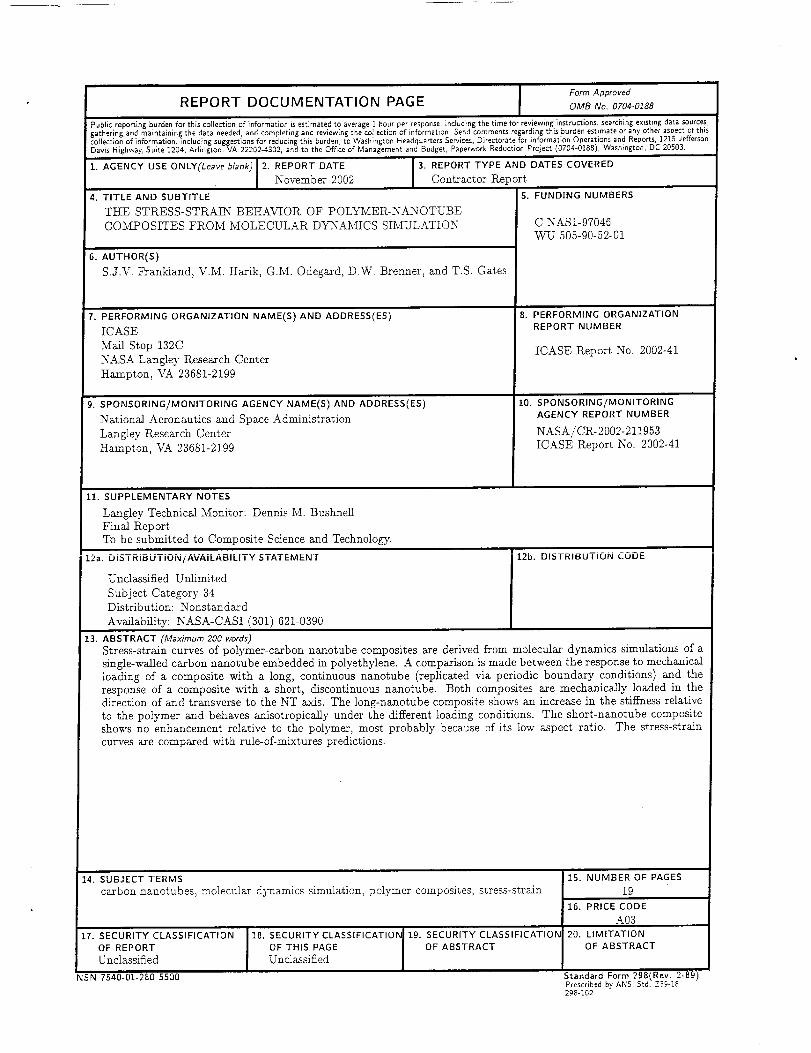
Public reporting burden for this collection of information is estimated to average1 hour per response,including the time for reviewinginstructions, searchingexisting data sources,gathering and maintaining the data needed,and completingand reviewingthe collectlon of information. Sendcommentsregarding this burden estimate or anyother aspectof thiscollection of information, includingsuggestionsfor reducing thls burden, to Washington HeadquartersServices,Directorate for informationOperationsand Reports,1215JeffersonDavis Highway, Suite 1204, Arlington, VA 22202-4302,and to the Of/ice of Management and Budget, PaperworkReduction Project (0704-0188), Washlngton,DC 20503.
1. AGENCY USE ONLY(Leaveb/ank) 2. REPORT DATE 3. REPORT TYPE AND DATES COVERED
November 2002 Contractor Report
4. TITLE AND SUBTITLE 5. FUNDING NUMBERS
THE STRESS-STRALN BEHAVIOR OF POLYSCER-NANOTUBE
COMPOSITES FROM MOLECULAR DYNAMICS SIMULATION C NAS1-97046VV_L/ 505-90-52-01
6. AUTHOR(S)
S.J.\q Frankland, V.M. Harik, G.M. Odegard, D.W. Brenner, and T.S. Gates
7. PERFORMING ORGANIZATION NAME(S) AND ADDRESS(ES)
ICASE
Mail Stop 132C
NASA Langley Research Center
Hampton, VA 23681-2199
9. SPONSORING/MONITORING AGENCY NAME(S) AND ADDRESS(ES)
National Aeronautics and Space Administration
Langley Research Center
Hampton, \6k 23681-2199
8. PERFORMING ORGANIZATIONREPORT NUMBER
ICASE Report No. 2002-41
10. SPONSORING/MONITORING
AGENCY REPORT NUMBER
NASA/OR-2002-211953
ICASE Report No. 2002-41
ii. SUPPLEMENTARY NOTES
Langley Technical Monitor: Dennis M. Bushnell
Final Report
To be submitted to Composite Science and Technology.
i2a. DISTRiBUTiON/AVAiLABiLiTY STATEMENT
Unclassified-Unlimit ed
Subject Category 34
Distribution: Nonstandard
Availability: NASA-CASI (301) 621-0390
' 12b. DISTRIBUTION CODE
13. ABSTRACT (Maximum 200 words)
Stress-strain curves of polymer-carbon nanotube composites are derived from molecular dynamics simulations of a
single-walled carbon nanotube embedded in polyethylene. A comparison is made between the response to mechanical
loading of a composite with a long, continuous nanotube (replicated via periodic boundary conditions) and the
response of a composite with a short, discontinuous nanotube. Both composites are mechanically loaded in the
direction of and transverse to the NT axis. The long-nanotube composite shows an increase in the stiffness relative
to the polymer and behaves anisotropically under the different loading conditions. The short-nanotube composite
shows no enhancement relative to the polymer, most probably because of its low aspect ratio. The stress-strain
curves are compared with rule-of-mixtures predictions.
14. SUBJECT TERMS
carbon nanotubes, molecular dynamics simulation, polymer composites, stress-strain
17. SECURITY CLASSIFICATION
OF REPORT
Unclassified
NSN ?'540-01-280-5500
18, SECURITY CLASSIFICATIOI_
OF THIS PAGE
Unclassified
15. NUMBER OF PAGES
19
16. PRICE CODE
A03
lg. SECURITY CLASSIFICATION 20. LIMITATION
OF ABSTRACT OF ABSTRACT
Standard Form 298(Rev. 2-B9)Prescribedby ANSI Std. Z39-18298-102