The STAR Heavy Flavor Tracker
40
1 Jim Thomas - LBL The STAR Heavy Flavor Tracker An Introduction and Brief Review of the Physics Goals at Mid- rapidity plus comments on tracking in a high multiplicity environment Jim Thomas Lawrence Berkeley National Laboratory May 29 th , 2011
-
Upload
anthony-maynard -
Category
Documents
-
view
26 -
download
0
description
The STAR Heavy Flavor Tracker An Introduction and Brief Review of the Physics Goals at Mid-rapidity plus comments on tracking in a high multiplicity environment Jim Thomas Lawrence Berkeley National Laboratory May 29 th , 2011. Lattice results. The Light Quark Program at RHIC is Compelling. - PowerPoint PPT Presentation
Transcript of The STAR Heavy Flavor Tracker

1Jim Thomas - LBL
The STAR Heavy Flavor TrackerAn Introduction and Brief Review of the Physics Goals at Mid-rapidity plus
comments on tracking in a high multiplicity environment
Jim Thomas
Lawrence Berkeley National Laboratory
May 29th, 2011

2Jim Thomas - LBL
The Light Quark Program at RHIC is Compelling
Lattice results
Its hot
Its dense
and it flowsat the partonic scale
and , too!
Spectra
Vn
Jets & Rcp
The evidence for a low viscosity, strongly interacting QGP is overwhelming, especially after QM 2011 (v3 , vn wow …!!)
3Jim Thomas - LBL
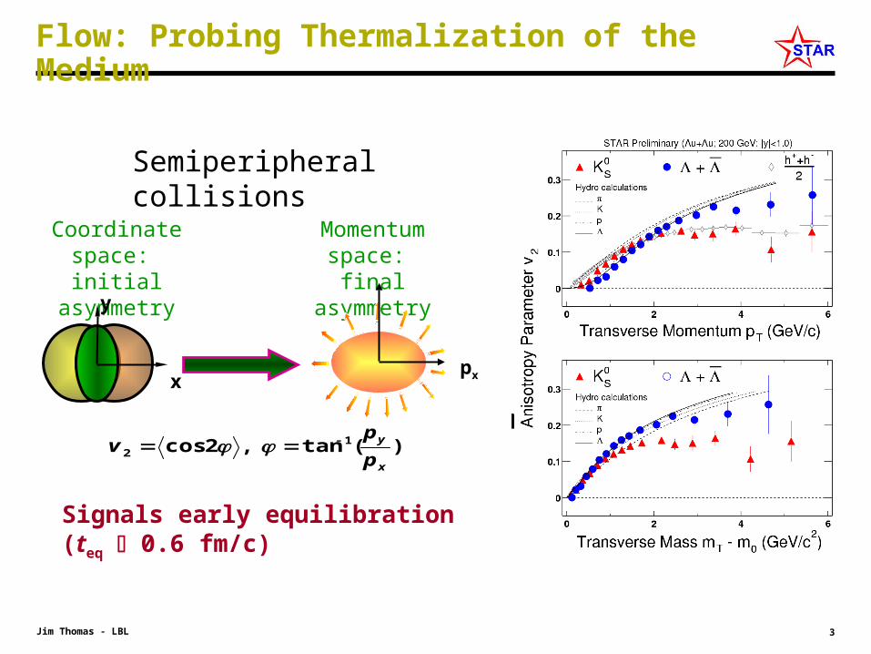
Flow: Probing Thermalization of the Medium
py
)(tan,2cos 12
x
y
p
pv
Coordinate space: initial asymmetry
Momentum space: final asymmetry
pxx
y
Semiperipheral collisions
Signals early equilibration (teq 0.6 fm/c)
4Jim Thomas - LBL
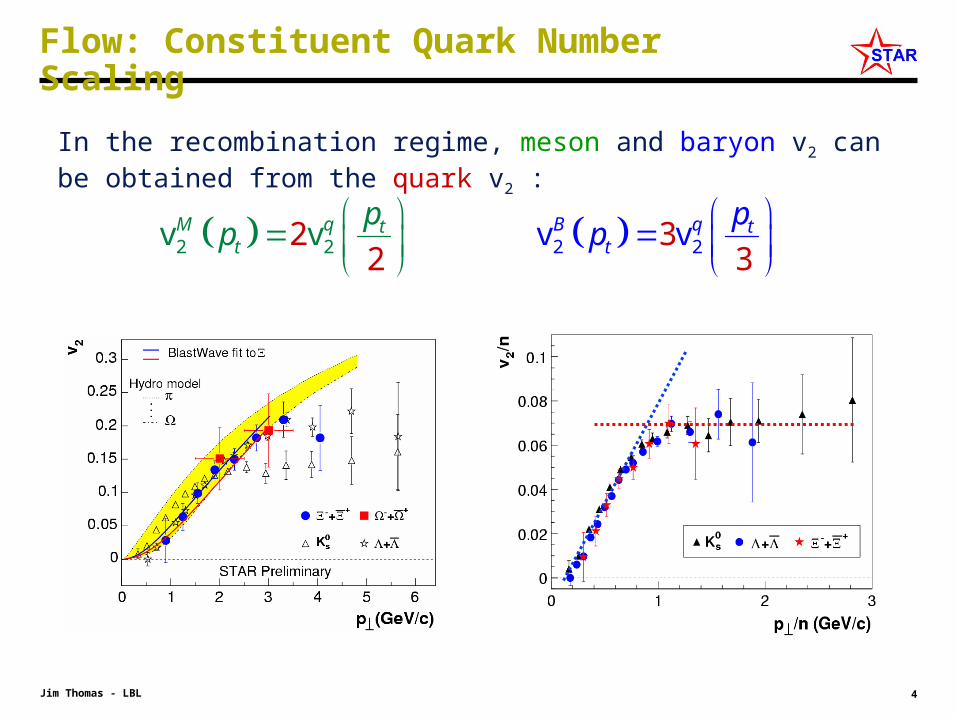
Flow: Constituent Quark Number Scaling
In the recombination regime, meson and baryon v2 can be obtained from the quark v2 :
2 2 2 2v22
v3
v3v Btt
q tM q tp ppp

5Jim Thomas - LBL
Scaling as a Function of (mT – m0)
• The light quark sector scales beautifully with v2/nq .vs. (mT – m0)/nq
– Note that pT < 1 GeV always did scale !
• The strange quark sector also scales with <v2> and the scaling holds at all centralities
• Even the meson
V2 /
nq
Does it work in the Charm Sector?
A strong test of the theoryYuting Bai, QM 2006 for the STAR Collaboration
STAR Preliminary work by Yan Lu

6Jim Thomas - LBL
Baryons vs. mesons
• Coalescence and fragmentation conspire at intermediate pT to give constituent quark number scaling and Baryon-Meson differences.
• Coalescence and fragmentation of charm quarks is different than for light quarks … so it is a strong test of the theory
• Coalescence of light quarks implies deconfinement and thermalization prior to hadronization
• How do baryons and mesons behave in the Charm sector?
• The Λc will be a fascinating test … and we might be able to do it with the HFT via Λc / D

7Jim Thomas - LBL
“Heavy Flavor” is the next frontier at RHIC
• A low viscosity, sQGP is the universally accepted hypothesis
• The next step in confirming this hypothesis is the proof of thermalization of the light quarks in RHIC collisions
• The key element in proving this assertion is to observe the flow of charm … because charm and beauty are unique in their mass structure
• If heavy quarks flow– frequent interactions among all quarks
– light quarks (u,d,s) likely to be thermalized
Current quark: a bare quark whose mass is due to electroweak symmetry breaking
Constituent quark: a bare quark that has been dressed by fluctuations in the QCD sea
8Jim Thomas - LBL
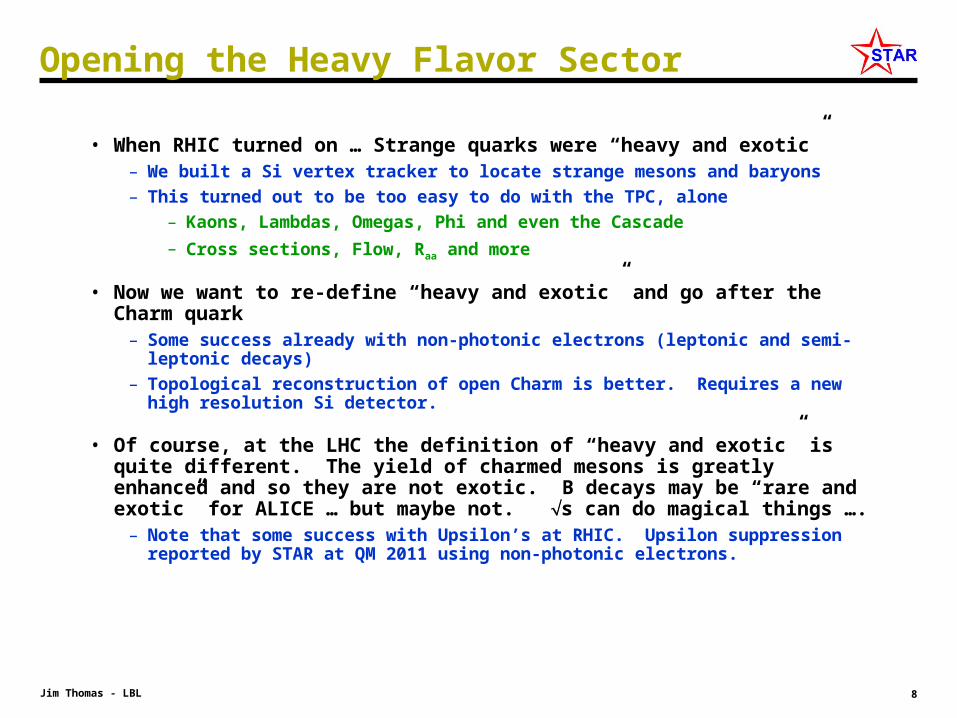
Opening the Heavy Flavor Sector
• When RHIC turned on … Strange quarks were “heavy and exotic”– We built a Si vertex tracker to locate strange mesons and baryons
– This turned out to be too easy to do with the TPC, alone
– Kaons, Lambdas, Omegas, Phi and even the Cascade
– Cross sections, Flow, Raa and more
• Now we want to re-define “heavy and exotic” and go after the Charm quark– Some success already with non-photonic electrons (leptonic and semi-leptonic
decays)
– Topological reconstruction of open Charm is better. Requires a new high resolution Si detector.
• Of course, at the LHC the definition of “heavy and exotic” is quite different. The yield of charmed mesons is greatly enhanced and so they are not exotic. B decays may be “rare and exotic” for ALICE … but maybe not. s can do magical things ….
– Note that some success with Upsilon’s at RHIC. Upsilon suppression reported by STAR at QM 2011 using non-photonic electrons.
9Jim Thomas - LBL
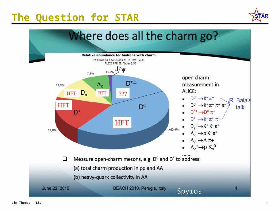
The Question for STAR
Spyros Margetis

10Jim Thomas - LBL
Hints of Elliptic Flow with Charm
Shingo Sakai, QM 2006 for the PHENIX Collaboration
• D e +X
Single electron spectra from PHENIX show hints of elliptic flow
Is it charm or beauty?
• The HFT will cut out large photonic backgrounds:
e+e-
and reduce other large stat. and systematic uncertainties
• STAR can make this measurement with 50 M Au+Au events in the HFT
• Smoking gun for thermalization at RHIC!
Better if we can do direct topological identification of Charm

11Jim Thomas - LBL
Heavy Flavor Energy Loss … RAA for Charm
• Heavy Flavor energy loss is an unsolved problem
– Gluon density ~ 1000 expected from light quark data
– Better agreement with the addition of inelastic E loss
– Good agreement only if they ignore Beauty …
• Beauty dominates single electron spectra above 5 GeV
• We can separate the Charm and Beauty by the direct topological identification of Charm
Theory from Wicks et al. nucl-th/0512076v2
Where is the contribution from Beauty?

12Jim Thomas - LBL
The HFT – Signature Physics Measurements
• hello
DOE milestone for 2016: “Measure production rates, high pT spectra, and correlations in heavy-ion collisions at √sNN = 200 GeV for identified hadrons with heavy flavor valence quarks to constrain the mechanism for parton energy loss in the QGP.”
Charmed Hadron v2
using 200 GeV Au+Au minimum bias collisions (500M events)
Charm-quark flow
Thermalization
of light-quarks
Charm-quark does
not flow
Drag coefficients
13Jim Thomas - LBL
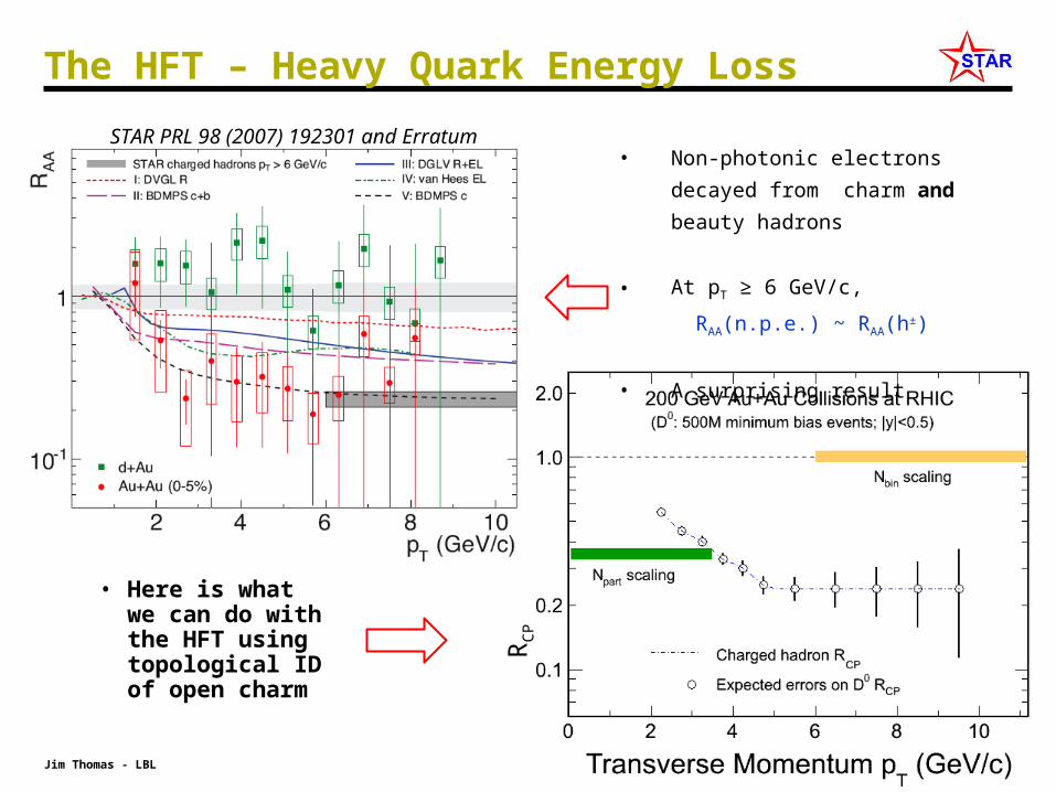
• Non-photonic electrons decayed
from charm and beauty hadrons
• At pT ≥ 6 GeV/c,
RAA(n.p.e.) ~ RAA(h±)
• A surprising result
The HFT – Heavy Quark Energy Loss
• Here is what we can do with the HFT using topological ID of open charm
RC
P
STAR PRL 98 (2007) 192301 and Erratum
14Jim Thomas - LBL
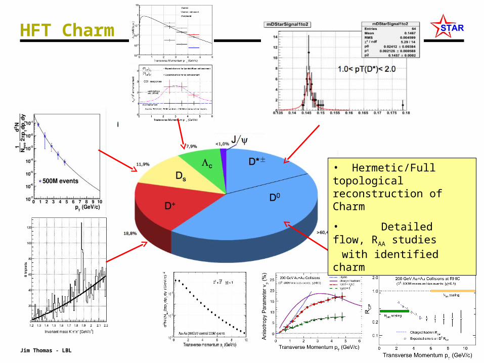
HFT Charm
• Hermetic/Full topological reconstruction of Charm
• Detailed flow, RAA studies with identified charm

15Jim Thomas - LBL
A Rich Physics Program
• There is a rich physics program when all of the STAR physics detectors are working together
– Flow in the Charm sector
– dE/dx in the Charm sector
– Recombination and RAA in the Charm sector
– Vector Mesons
– Charm Angular Correlations
– non-photonic electrons
– …

16Jim Thomas - LBL
The HFT: The Challenge
The STAR HFT has the capability to reconstruct the displaced vertex of
D0 K (B.R 3.8%, c = 123 m) Λc Kp (B. R. 5.0%, c = 59.9 m)and more …
• Primary Challenges
– Neutral particle decay
– Proper lifetime, c, 123 m
– Find a common vertex away from the primary vertex
– Identify daughters, measure pT , and reconstruct the invariant mass
Topological Reconstruction of Open Charm

17Jim Thomas - LBL
The STAR Detector
• hello
MRPC ToF barrelMRPC ToF barrel
100% ready for run 10 100% ready for run 10 (now!)(now!)
BBC
PMD
FPD
FMS
EMC barrelEMC End Cap
DAQ1000DAQ1000
FGT
Completed
Ongoing
MTD
R&DHFT
TPC
FHC
HLT

18Jim Thomas - LBL
The HFT – The configuration
Beampipe
SSDIST
Pixel Detector
10
20
30
-30
-10
-20
0
• The HFT puts 4 layers of Silicon around the vertex
• Provides 8 m space point resolution @ 2.5 cm
• 30 m vertex resolution @ 1 GeV, 10 m @ 5 GeV
• Works at high rate (~ 800 Hz – 1K)
• Does topological reconstruction of open charm
• Will be ready for the 2014 run
19Jim Thomas - LBL
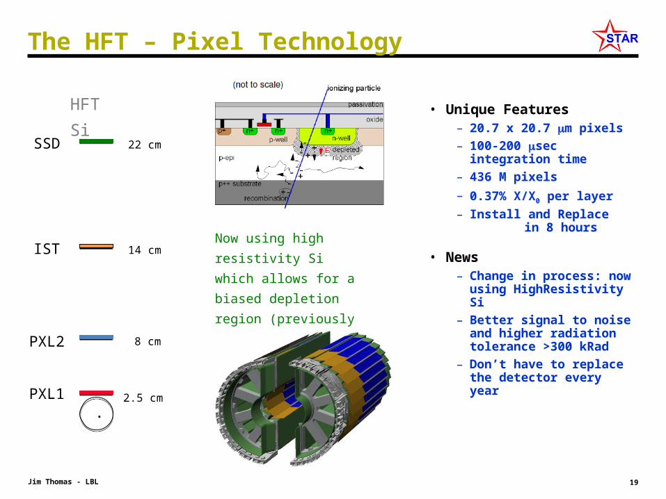
The HFT – Pixel Technology
• Unique Features– 20.7 x 20.7 m pixels
– 100-200 sec integration time
– 436 M pixels
– 0.37% X/X0 per layer
– Install and Replace in 8 hours
• News– Change in process: now
using HighResistivity Si
– Better signal to noise and higher radiation tolerance >300 kRad
– Don’t have to replace the detector every year
Now using high resistivity Si
which allows for a biased
depletion region (previously
relied upon diffusion to collect
the charge)
22 cm
14 cm
8 cm
2.5 cm
.
HFT Si
SSD
IST
PXL2
PXL1

20Jim Thomas - LBL
Tracking: Getting a Boost from the TPC
• The TPC provides good but not excellent resolution at the vertex and at other intermediate radii
~ 1 mm
• The TPC provides an excellent angular constraint on the path of a predicted track segment
– This is very powerful.
– It gives a parallel beam with the addition of MCS from the IFC
• The best thing we can do is to put a pin-hole in front of the parallel beam track from the TPC
– This is the goal for the Si trackers: SSD, IST, and PXL
• The SSD and IST do not need extreme resolution. Instead, the goal is to maintain the parallel beam and not let it spread out
– MCS limited
– The PXL does the rest of the work
TPC
MCS Cone
VTX
The Gift of the TPC
OFC
IFC

21Jim Thomas - LBL
– Goal: graded resolution and high efficiency from the outside in
– TPC – SSD – IST – PXL
– TPC pointing resolution at the SSD is ~ 1 mm
– SSD pointing at the IST is ~ 400 m (200 x 800)
– IST pointing at PXL 2 is ~ 400 m (200 x 800)
– PXL 2 pointing at PXL1 is ~ 125 m (90 x 175 )
– PXL1 pointing at the VTX is ~ 40 m (Kaon at 750 MeV)
Overview & Goals for Si Detectors Inside the TPC
The challenge is to find tracks in a high density environment with high efficiency because a D0 needs single track 2
~ 50 cm

22Jim Thomas - LBL
The Simplest ‘Simulation’ – basic performance check
• Study the last two layers of the system with basic telescope equations with MCS
– PXL 1 and PXL 2 alone ( no beam pipe )
– Give them 9 m resolution
0
( / )13.6mcs
MeV c x
p X
2 22 2 2 22 11 2 2 1
2 2
2 1sin ( )mcs rr r
r r
hh
• In the critical region for Kaons from D0 decay, 750 MeV to 1 GeV, the PXL single track pointing resolution is predicted to be 20-30 m … which is sufficient to pick out a D0 with c = 125 m
• The system (and especially the PXL detector) is operating at the MCS limit
• In principle, the full detector can be analyzed 2 layers at a time …
TPC alone
PXL alone

23Jim Thomas - LBL
Graded Resolution from the Outside In
• A PXL detector requires external tracking to be a success– The TPC and intermediate tracking provide graded resolution from the
outside-in• The intermediate layers form the elements of a ‘hit finder’
– The spectral resolution is provided by the PXL layers• The next step is to ensure that the hit finding can be done
efficiently at every layer in a high hit density environment
TPCvtx
PXL alone
TPCSSDSSDISTISTPXL2PXL2PXL1PXL1VTX

24Jim Thomas - LBL
Central Collisions: Density of hits on the Detectors
dN dN d
dz d dz
2 2
1( , )
dr z
dz r z
where
22
1 700( ) 17.8
2 2
dN dNCentral cm
dA dz r r
Au+Au Luminosity (RHIC-II) 80 x 1026 cm-2s-1
dn/d (Central) 700 dn/d (MinBias) 170 MinBias cross section 10 barns MinBias collision rate (RHIC-II) 80 kHz Interaction diamond size, σ 15 cm Integration time for Pixel Chips 200 sec
Radius Simple Formula|| = 0
|| < 0.2 || < 1.0
PXL 1 2.5 cm 17.8 cm-2 19.0 cm-2 15.0 cm-2
PXL 2 8.0 cm 1.7 cm-2 1.8 cm-2 1.5 cm-2
IST 14.0 cm 0.57 cm-2 0.66 cm-2 0.52 cm-2
SSD 23.0 cm 0.21 cm-2 0.23 cm-2 0.19 cm-2
The density of hits is not large compared to the number of pixels on each layer. The challenge, instead, is for tracking to find the good hits in this dense environment.
Slightly
conservative
numbers
100,000
pixels cm-2
25Jim Thomas - LBL
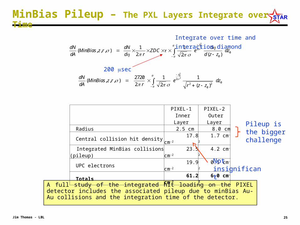
MinBias Pileup – The PXL Layers Integrate over Time
A full study of the integrated hit loading on the PIXEL detector includes the associated pileup due to minBias Au-Au collisions and the integration time of the detector.
2022
00
1 1( , , , )
2 ( )2
za
a
dN dN dMinBias z r ZDC e dz
dA d r d z z
2022
02 20
2720 1 1( , , , )
2 2 ( )
za
a
dNMinBias z r e dz
dA r r z z
PIXEL-1 Inner Layer
PIXEL-2 Outer Layer
Radius 2.5 cm 8.0 cm Central collision hit density 17.8 cm-2 1.7 cm-2
Integrated MinBias collisions (pileup) 23.5 cm-2 4.2 cm-2
UPC electrons 19.9 cm-2 0.1 cm-2
Totals 61.2 cm-2 6.0 cm-2
Pileup is the bigger challenge
Integrate over time and interaction diamond
200 sec
Not insignificant
26Jim Thomas - LBL
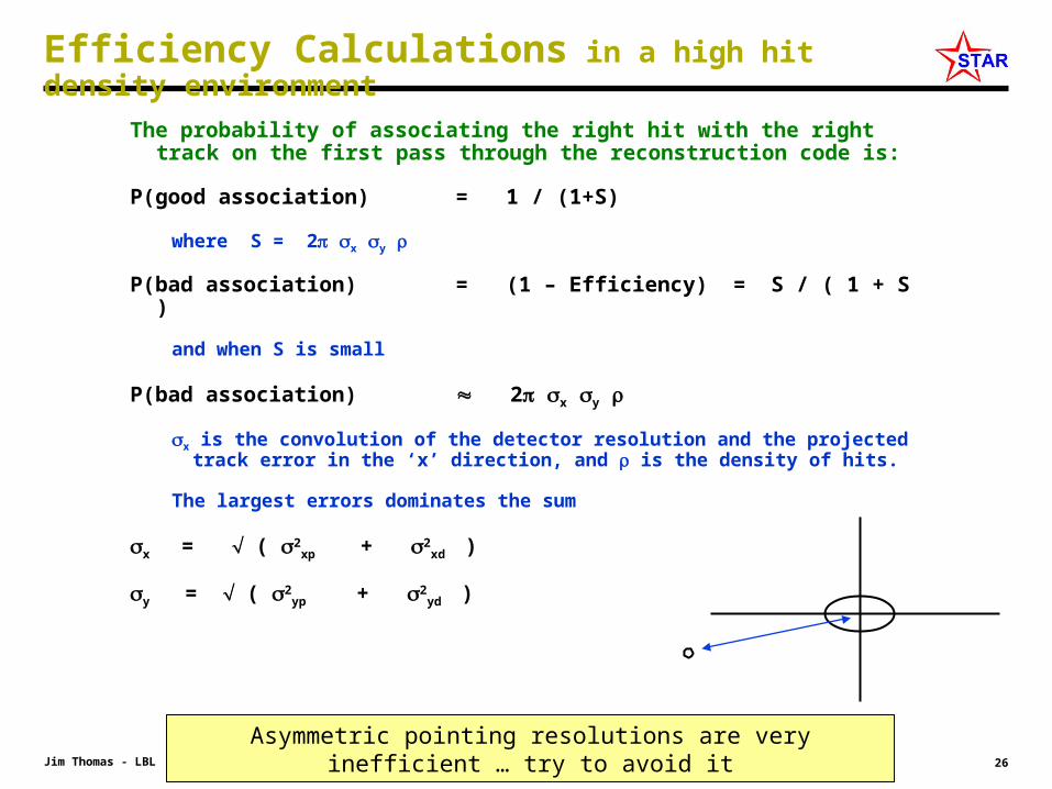
Efficiency Calculations in a high hit density environment
The probability of associating the right hit with the right track on the first pass through the reconstruction code is:
P(good association) = 1 / (1+S)
where S = 2 x y
P(bad association) = (1 – Efficiency) = S / ( 1 + S )
and when S is small
P(bad association) 2 x y
x is the convolution of the detector resolution and the projected track error in the ‘x’ direction, and is the density of hits.
The largest errors dominates the sum
x = ( 2xp + 2
xd )
y = ( 2yp + 2
yd )
Asymmetric pointing resolutions are very inefficient … try to avoid it

27Jim Thomas - LBL
TPC Pointing at the PXL Detector
• The TPC pointing resolution on the outer surface of the PXL Detector is greater than 1 mm … but lets calculate what the TPC can do alone
– Assume the new radial location at 8.0 cm for PXL-2, with 9 m detector resolution in each pixel layer and a 200 sec detector
– Notice that the pointing resolution on PXL-1 is very good even though the TPC pointing resolution on PXL-2 is not so good
• The probability of a good hit association on the first pass– 55% on PXL2
– 95% on PXL1
Radius PointResOn(R-)
PointResOn(Z)
Hit Density
8.0 cm 1.4 mm 1.5 mm 6.0
2.5 cm 90 m 110 m 61.5
This is a surprise: The hard work gets done at 8 cm!
The purpose of the intermediate tracking layers is to make 55% go up to ~100%
All values quoted for mid-rapidity Kaons at 750 MeV/c

28Jim Thomas - LBL
The performance of the TPC acting alone
• The performance of the TPC acting alone depends on the integration time of the PXL chip
P(good association) = 1 / (1+S) where S = 2 x y
Integration Time (sec)
Sin
gle
Laye
r E
ffici
ency
The purpose of intermediate tracking layers is to make 55% go up to ~100%
Note that the hard work gets done at PXL layer 2. This is a surprise.
29Jim Thomas - LBL
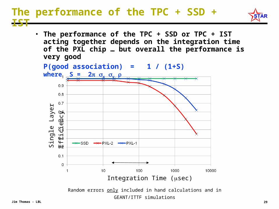
The performance of the TPC + SSD + IST
• The performance of the TPC + SSD or TPC + IST acting together depends on the integration time of the PXL chip … but overall the performance is very good
P(good association) = 1 / (1+S) where S = 2 x y
Integration Time (sec)
Sin
gle
Laye
r E
ffici
ency
Random errors only included in hand calculations and in GEANT/ITTF simulations
30Jim Thomas - LBL
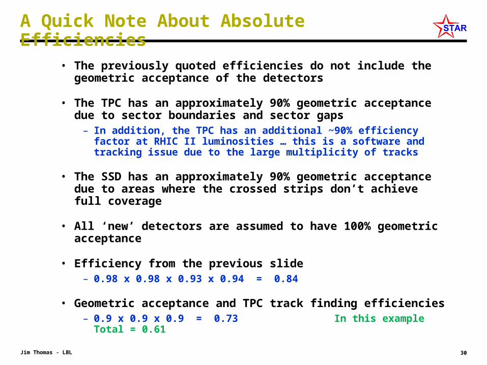
A Quick Note About Absolute Efficiencies
• The previously quoted efficiencies do not include the geometric acceptance of the detectors
• The TPC has an approximately 90% geometric acceptance due to sector boundaries and sector gaps
– In addition, the TPC has an additional ~90% efficiency factor at RHIC II luminosities … this is a software and tracking issue due to the large multiplicity of tracks
• The SSD has an approximately 90% geometric acceptance due to areas where the crossed strips don’t achieve full coverage
• All ‘new’ detectors are assumed to have 100% geometric acceptance
• Efficiency from the previous slide– 0.98 x 0.98 x 0.93 x 0.94 = 0.84
• Geometric acceptance and TPC track finding efficiencies– 0.9 x 0.9 x 0.9 = 0.73 In this example Total = 0.61

31Jim Thomas - LBL
Single Track Efficiencies – Hand Calc .vs. ITTF
The efficiency for finding tracks in central Au+Au collisions in the STAR TPC and the HFT. Finite acceptance effects for the TPC and SSD are included in the simulations. The quoted efficiency from GEANT/ITTF is for || < 1.0 and for tracks coming from the primary vertex with |vz| < 5 cm.
Hand Calculations
Hand calculations assume the acceptance is flat in pT and assume a single track at = 0.5
32Jim Thomas - LBL
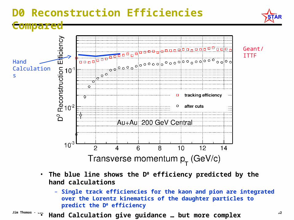
D0 Reconstruction Efficiencies Compared
Geant/ITTF
• The predicted absolute efficiency of the HFT detector. – The red squares show the efficiency for finding the D0 meson with the full set
of Geant/ITTF techniques.
• The green line shows the D0 efficiency predicted by the Geant/ITTF single particle efficiencies
• The blue line shows the D0 efficiency predicted by the hand calculations– Single track efficiencies for the kaon and pion are integrated over the Lorentz
kinematics of the daughter particles to predict the D0 efficiency
• Hand Calculation give guidance … but more complex questions should be answered by the full suite of tools available to Geant/ITTF
Hand Calculations

33Jim Thomas - LBL
A Robust Design
There is a rich physics program that can be addressed with the HFT in STAR
• The HFT is thin, unique, innovative and robust
• The designs have been tested extensively with hand calculations and more carefully with specific examples tested with GEANT/ITTF simulations

34Jim Thomas - LBL
Summary
• The HFT will explore the Charm sector at RHIC
• We will do direct topological reconstruction of Charm
• Our measurements will be unique at RHIC
• The key measurements include– V2
– Energy Loss
– Charm Spectra, RAA & Rcp
– Vector mesons
– Angular Correlations
• The technology is available on an appropriate schedule
35Jim Thomas - LBL
Backup Slides

36Jim Thomas - LBL
FY09 FY10 FY11 FY12 FY13 FY14 FY15
HFT Construction
HFTOperation
MTDConstruction
MTDOperation
HLT Development
HLT Operation
Finish HFT in time for the 2014 run
Finish MTD project by Mar, 2014 and make 80% of the full system ready for year 2014 run
HLT is seeking funds but is projected to be under development through FY15,
and will be available for physics at all times
Three STAR Upgrade Projects
37Jim Thomas - LBL
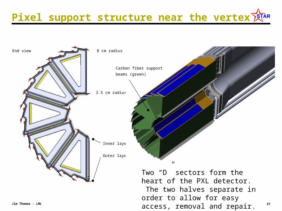
Pixel support structure near the vertex
2.5 cm radius
8 cm radius
Inner layer
Outer layer
End view
Carbon fiber support beams
(green)
Two “D” sectors form the heart of the PXL detector. The two halves separate in order to allow for easy access, removal and repair.
38Jim Thomas - LBL
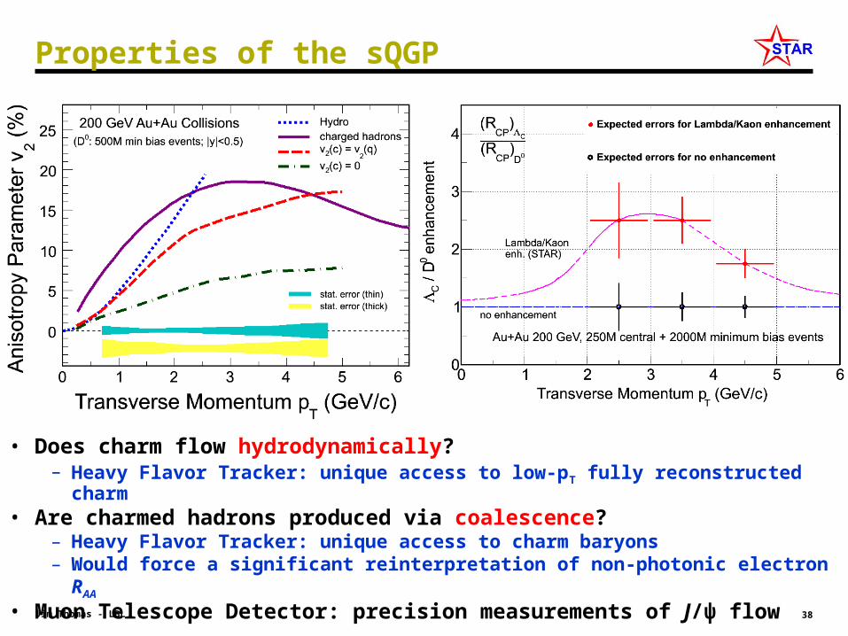
• Does charm flow hydrodynamically?– Heavy Flavor Tracker: unique access to low-pT fully reconstructed charm
• Are charmed hadrons produced via coalescence?– Heavy Flavor Tracker: unique access to charm baryons– Would force a significant reinterpretation of non-photonic electron RAA
• Muon Telescope Detector: precision measurements of J/ψ flow
Properties of the sQGP

39Jim Thomas - LBL
Calculating the Performance of the Detector
• Billoir invented a matrix method for evaluating the performance of a detector system including MCS and dE/dx
– NIM 225 (1984) 352.
• The ‘Information Matrices’ used by Billoir are the inverse of the more commonly used covariance matrices
– thus, ’s are propagated through the system
• The calculations can be done by ‘hand’ or by ‘machine’ (with chains)
• STAR ITTF ‘machine’ uses a similar method (aka a Kalman Filter)– The ‘hand calculations’ go outside-in
– STAR Software goes outside-in and then inside-out, and averages the results, plus follows trees of candidate tracks. It is ‘smart’ software.
MCS D M MCS D M MCS
40Jim Thomas - LBL
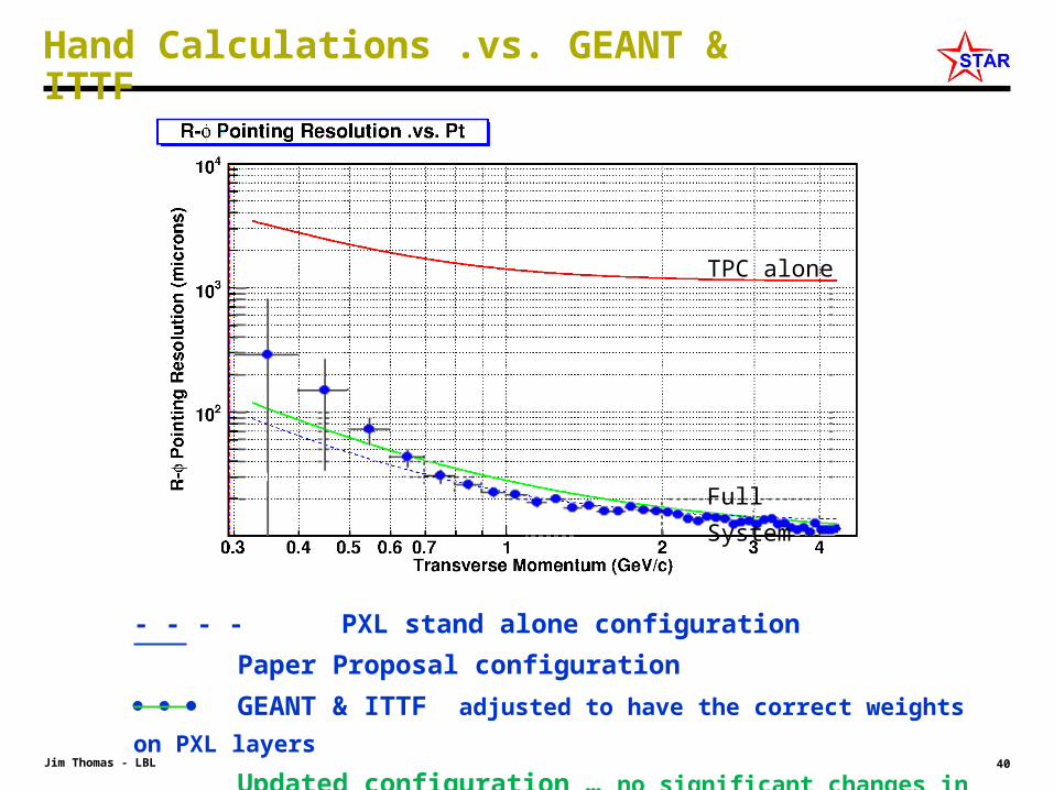
Hand Calculations .vs. GEANT & ITTF
- - - - PXL stand alone configuration
Paper Proposal configuration
GEANT & ITTF adjusted to have the correct weights on PXL
layers
Updated configuration … no significant changes in pointing at
VTX
TPC alone
Full System