
The Spitzer Space Telescope - IRSA · PDF fileThe Spitzer Space Telescope, which has operated...
8
The Spitzer Space Telescope Michael Werner Downloaded from SPIE Digital Library on 09 Feb 2012 to 66.165.46.178. Terms of Use: http://spiedl.org/terms
Transcript of The Spitzer Space Telescope - IRSA · PDF fileThe Spitzer Space Telescope, which has operated...
The Spitzer Space Telescope
Michael Werner
Downloaded from SPIE Digital Library on 09 Feb 2012 to 66.165.46.178. Terms of Use: http://spiedl.org/terms
The Spitzer Space Telescope
Michael WernerCalifornia Institute of TechnologyJet Propulsion LaboratoryPasadena, California 91107E-mail: [email protected]
Abstract. The Spitzer Space Telescope, which has operated very suc-cessfully since 2003 in its unique Earth-trailing solar orbit, is NASA’sGreat Observatory for infrared astronomy. We provide a quick overviewof the optical characteristics of Spitzer and review the observatory design.The main emphasis is on two unique on-orbit activities used to optimizethe scientific return from Spitzer: 1. an unusual approach to focusing thetelescope that minimized the use of the cryogenic focus mechanism, and2. a methodology for extending the cryogenic lifetime of Spitzer by activelycontrolling the telescope temperature. © 2012 Society of Photo-Optical Instrumen-tation Engineers (SPIE). [DOI: 10.1117/1.OE.51.1.011008]
Subject terms: cryogenic systems; infrared; space telescope; Spitzer; telescopefocus; thermal control.
Paper 110711SSP received Jun. 23, 2011; revised manuscript received Sep. 26,2011; accepted for publication Oct. 12, 2011; published online Feb. 3, 2012.
1 IntroductionThe launch of the National Aeronautics and Space Admin-istration’s Spitzer Space Telescope (Spitzer) in August 2003provided the scientific community the most powerful tool yetavailable for astronomical explorations between 3.6 and160 μm. Spitzer combines the intrinsic sensitivity of a cryo-genic telescope in space with the tremendous imaging andspectroscopic capabilities of the new generation of infrareddetector arrays. Spitzer’s unique cryothermal architectureand Earth-trailing solar orbit have enabled the spacecraftto continue operating in a totally passively cooled configura-tion for more than two years after the depletion of the 350 Lof liquid helium carried at launch. Well over 2000 papersbased on Spitzer studies of objects from near-Earth asteroidsto the most distant known galaxies have appeared in therefereed literature since launch, and the observatory remainsas robust and productive as ever.
The Spitzer telescope is not remarkable in comparison tocontemporaneous and future space-optical systems. In thiscontribution, we provide a quick overview of the Spitzertelescope but concentrate principally on two activities car-ried out during the mission that are of particular technicalinterest—the process by which the telescope was focusedon orbit and the approach used to extend the liquid heliumlifetime by matching the telescope temperature to the needsof each scientific instrument in turn. Readers seeking a morecomplete end-to-end technical description of Spitzer, includ-ing the instruments and the operations, are referred to Gehrzet al.1 Werner2 and Rieke3 have presented historical accountsof the development of Spitzer. Summaries of the scientificbounty of Spitzer are presented by Werner et al.4 and Soiferet al.,5 and in the proceedings of the 2009 Spitzer ScienceConference.6
2 The Spitzer TelescopeThe Spitzer optical design is a conventional Ritchey–Chretien two-mirror system. The primary and secondarymirrors and the metering tower that connects them are allfabricated from hot isostatically pressed (HIP) beryllium
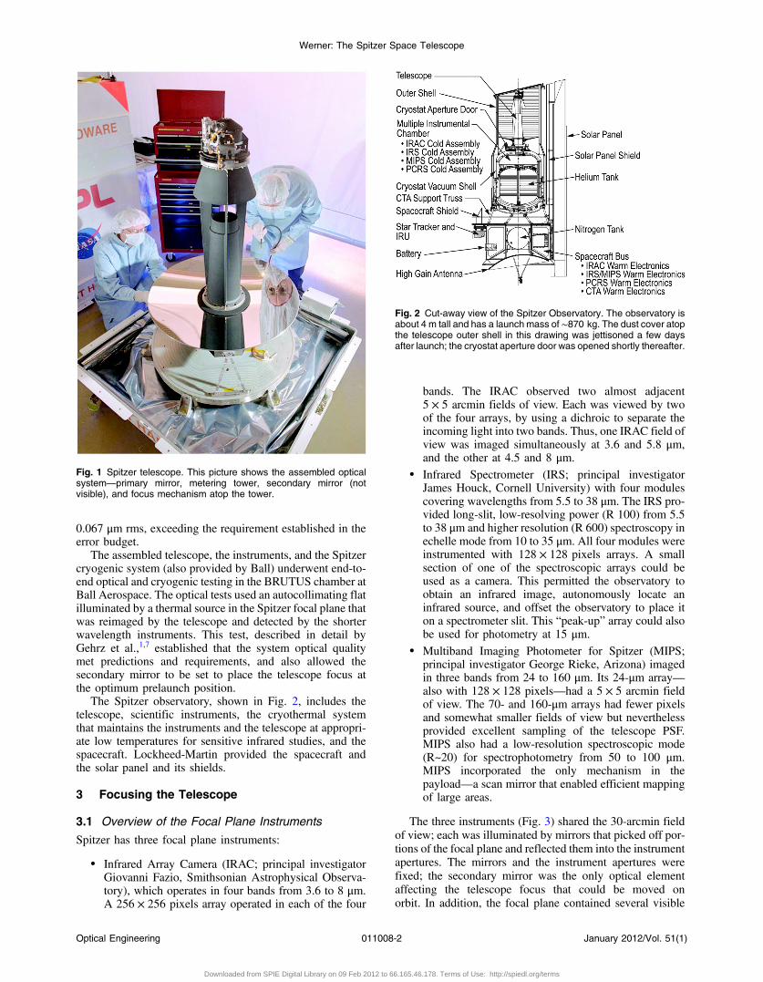
to maintain alignment and minimize stresses on coolingfrom room temperature to the operating temperature of5 K. Beryllium was the material of choice because of itslightweight, good thermal properties, and high strength-to-mass ratio. The telescope has a ∼90-cm-diameter mirror, fig-ured and stopped down to produce an 85-cm f ∕1.2-diameterprimary aperture, and a 12-cm-diameter secondary mirror.The secondary mirror is mounted on a cryogenic focusmechanism, which provides high-precision motion in theaxial direction and was used to focus the telescope on-orbit.The assembled optical system (Fig. 1) has a length of about90 cm. The mass of the fully assembled telescope, includingmirrors, metering tower, focus mechanism, barrel baffle, andthe hardware required to mount it to the Spitzer cryostat, is55 kg. The focal length is 10.2 m and the plate scale is20 arcsec∕mm. Fabrication of the telescope was begun atHughes-Danbury (now Goodrich) and finished at Ball Aero-space. The mirrors were figured by Tinsley Laboratories, andmuch of the cryogenic testing was done at the Jet PropulsionLaboratory (JPL).
The telescope was required to provide diffraction-limitedimages at a wavelength of 6.5 μm over a 30-arcmin field ofview. This corresponds to a wavefront error of 0.46 μm at thefocal plane; when this was flowed down to and through thetelescope, the corresponding requirement on the primarymirror surface error was 0.075 μm rms at the operating tem-perature of 5 K. Because the primary was figured at roomtemperature, the process of guaranteeing satisfactory cryo-genic performance was neither trivial nor straightforward.Careful initial preparation of the material and annealing/stress relief during the figuring allowed the optics team toestablish by test that the mirror deformed predictably (i.e.,without hysteresis) on successive cooldowns. The finalfigure was thus achieved by measuring the mirror figure atoperating temperature in a cryogenic test facility at JPL,comparing the cryogenic figure with the room-temperaturefigure, and taking the difference. This defined a “hit map”specifying the changes to be polished into the mirror atroom temperature so that the mirror would distort into therequired optical configuration upon cooldown. Two cyclesof this process, referred to by the ungainly name of “cryonullfiguring,” brought the primary mirror to a surface error of0091-3286/2012/$25.00 © 2012 SPIE
Optical Engineering 011008-1 January 2012/Vol. 51(1)
Optical Engineering 51(1), 011008 (January 2012)
Downloaded from SPIE Digital Library on 09 Feb 2012 to 66.165.46.178. Terms of Use: http://spiedl.org/terms
0.067 μm rms, exceeding the requirement established in theerror budget.
The assembled telescope, the instruments, and the Spitzercryogenic system (also provided by Ball) underwent end-to-end optical and cryogenic testing in the BRUTUS chamber atBall Aerospace. The optical tests used an autocollimating flatilluminated by a thermal source in the Spitzer focal plane thatwas reimaged by the telescope and detected by the shorterwavelength instruments. This test, described in detail byGehrz et al.,1,7 established that the system optical qualitymet predictions and requirements, and also allowed thesecondary mirror to be set to place the telescope focus atthe optimum prelaunch position.
The Spitzer observatory, shown in Fig. 2, includes thetelescope, scientific instruments, the cryothermal systemthat maintains the instruments and the telescope at appropri-ate low temperatures for sensitive infrared studies, and thespacecraft. Lockheed-Martin provided the spacecraft andthe solar panel and its shields.
3 Focusing the Telescope
3.1 Overview of the Focal Plane Instruments
Spitzer has three focal plane instruments:
• Infrared Array Camera (IRAC; principal investigatorGiovanni Fazio, Smithsonian Astrophysical Observa-tory), which operates in four bands from 3.6 to 8 μm.A 256 × 256 pixels array operated in each of the four
bands. The IRAC observed two almost adjacent5 × 5 arcmin fields of view. Each was viewed by twoof the four arrays, by using a dichroic to separate theincoming light into two bands. Thus, one IRAC field ofview was imaged simultaneously at 3.6 and 5.8 μm,and the other at 4.5 and 8 μm.
• Infrared Spectrometer (IRS; principal investigatorJames Houck, Cornell University) with four modulescovering wavelengths from 5.5 to 38 μm. The IRS pro-vided long-slit, low-resolving power (R 100) from 5.5to 38 μm and higher resolution (R 600) spectroscopy inechelle mode from 10 to 35 μm. All four modules wereinstrumented with 128 × 128 pixels arrays. A smallsection of one of the spectroscopic arrays could beused as a camera. This permitted the observatory toobtain an infrared image, autonomously locate aninfrared source, and offset the observatory to place iton a spectrometer slit. This “peak-up” array could alsobe used for photometry at 15 μm.
• Multiband Imaging Photometer for Spitzer (MIPS;principal investigator George Rieke, Arizona) imagedin three bands from 24 to 160 μm. Its 24-μm array—also with 128 × 128 pixels—had a 5 × 5 arcmin fieldof view. The 70- and 160-μm arrays had fewer pixelsand somewhat smaller fields of view but neverthelessprovided excellent sampling of the telescope PSF.MIPS also had a low-resolution spectroscopic mode(R~20) for spectrophotometry from 50 to 100 μm.MIPS incorporated the only mechanism in thepayload—a scan mirror that enabled efficient mappingof large areas.
The three instruments (Fig. 3) shared the 30-arcmin fieldof view; each was illuminated by mirrors that picked off por-tions of the focal plane and reflected them into the instrumentapertures. The mirrors and the instrument apertures werefixed; the secondary mirror was the only optical elementaffecting the telescope focus that could be moved onorbit. In addition, the focal plane contained several visible
Fig. 1 Spitzer telescope. This picture shows the assembled opticalsystem—primary mirror, metering tower, secondary mirror (notvisible), and focus mechanism atop the tower.
Fig. 2 Cut-away view of the Spitzer Observatory. The observatory isabout 4 m tall and has a launch mass of ∼870 kg. The dust cover atopthe telescope outer shell in this drawing was jettisoned a few daysafter launch; the cryostat aperture door was opened shortly thereafter.
Werner: The Spitzer Space Telescope
Optical Engineering 011008-2 January 2012/Vol. 51(1)
Downloaded from SPIE Digital Library on 09 Feb 2012 to 66.165.46.178. Terms of Use: http://spiedl.org/terms
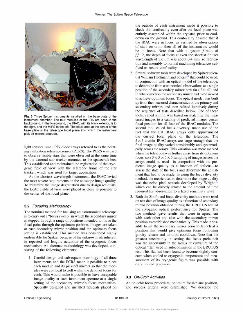
light sensors, small PIN diode arrays referred to as the point-ing calibration reference sensor (PCRS). The PCRS was usedto observe visible stars that were observed at the same timeby the external star tracker mounted to the spacecraft bus.This established and maintained the registration of the cryo-genic field of view with the reference frame of the startracker, which was used for target acquisition.
As the shortest wavelength instrument, the IRAC leviedthe most severe requirements on the telescope image quality.To minimize the image degradation due to design residuals,the IRAC fields of view were placed as close as possible tothe center of the focal plane.
3.2 Focusing Methodology
The nominal method for focusing an astronomical telescopeis to carry out a “focus sweep” in which the secondary mirroris stepped through a range of positions intended to move thefocal point through the optimum position. Images are takenat each secondary mirror position and the optimum focussetting is established. This method was considered highlyundesirable for Spitzer because of the unknown risk inherentin repeated and lengthy actuation of the cryogenic focusmechanism. An alternate methodology was developed, con-sisting of the following elements:
1. Careful design and subsequent metrology of all threeinstruments and the PCRS made it possible to placeeach module and its pick-off mirrors so that the mod-ules were confocal to well within the depth of focus foreach. This would make it possible to have acceptableimage quality at each instrument aperture at a singlesetting of the secondary mirror’s focus mechanism.Specially designed and installed fiducials placed on
the outside of each instrument made it possible tocheck this confocality even after the focal plane wasentirely assembled within the cryostat, prior to cool-down on the ground. This confocality ensured that ifthe IRAC were in focus, as verified by observationsof stars on orbit, then all of the instruments wouldbe in focus. Note that with a system f -ratio off ∕1.2, the depth of focus at even the shortest Spitzerwavelength of 3.6 μm was about 0.4 mm, so fabrica-tion and assembly to normal machining tolerances suf-ficed to ensure confocality.
2. Several software tools were developed by Spitzer scien-tist William Hoffmann and others8,9 that could be used,in conjunction with an optical model of the telescope,to determine from astronomical observations at a singleposition of the secondary mirror how far (if at all) andin what direction the secondary mirror had to be movedto achieve optimum focus. The optical model was builtup from the measured characteristics of the primary andsecondary mirrors and then refined iteratively duringthe sequence of tests described below. One of thesetools, called Simfit, was based on matching the mea-sured images to a catalog of predicted images versusfocal position for all four of the IRAC modules. Thesecond tool, called focus diversity, made use of thefact that the flat IRAC arrays only approximatedthe curved focal plane of the telescope. The5 × 5 arcmin IRAC arrays are large enough that thefinal image quality varied considerably and systemati-cally across the arrays. This variation was more markedwhen the telescope was further away from its optimumfocus, so a 3 × 3 or 5 × 5 sampling of images across thearrays could be used—in comparison with the pre-dicted image quality as a function of defocus—toassess the state of the focus and determine the adjust-ment that had to be made. In using the focus diversitymethod, the metric used to determine the image qualitywas the noise pixel statistic developed by Wright,10
which can be directly related to the amount of timerequired for observation to a fixed sensitivity level.
3. Both the Simfit and focus diversity methods were usedon test data of image quality as a function of secondarymirror position obtained during the BRUTUS test ofthe cryogenic optical performance for Spitzer. Thetwo methods gave results that were in agreementwith each other and also with the secondary mirrorposition as established mechanically. This made it pos-sible to set the secondary mirror prior to launch at aposition that would give optimum focus followinggravity release and on-orbit cooldown. Note that thegreatest uncertainty in setting the focus prelaunchwas the uncertainty in the radius of curvature of theoptical “flat” used in autocollimation in the BRUTUStest. This flat had been found to become slightly con-cave when cooled to cryogenic temperature and mea-surement of its cryogenic figure was possible withonly limited precision.
3.3 On-Orbit Activities
An on-orbit focus procedure, optimum focal-plane position,and success criteria were established. We describe the
Fig. 3 Three Spitzer instruments installed on the base plate of theinstrument chamber. The four modules of the IRS are seen in thebackground. In the foreground, the IRAC, with its black exterior, is tothe right, and the MIPS to the left. The black area at the center of thebase plate is the telescope focal plane into which the instrumentpick-off mirrors protrude.
Werner: The Spitzer Space Telescope
Optical Engineering 011008-3 January 2012/Vol. 51(1)
Downloaded from SPIE Digital Library on 09 Feb 2012 to 66.165.46.178. Terms of Use: http://spiedl.org/terms
position of the telescope focal plane in millimeters of devia-tion from the optimum position. The secondary magnifica-tion of the Spitzer telescope is 100, and the secondary mirroractuator had a step size of a fraction of 1 μm. Thus it waspossible to adjust the position of the focal plane in stepssmaller than 0.1 mm, much less than the depth of focusfor the shortest wavelength instrument. Similarly, the numer-ical methods of Hoffmann et al. had been shown to be cap-able of determining the position of the focal plane to betterthan 0.1 mm. The on-orbit procedure was rehearsed prior tolaunch with a double-blind test in which simulated imagesfor a known focal-plane position were input to the system,and the analysis team properly retrieved and determined theoffset. A level of initial on-orbit defocus was established thatwould trigger an anomaly response. Following initial cool-down, the estimated defocus did not exceed this limit (whichwas about 1.8 mm away from the target best focus) and thefocus procedure was initiated. Details of the on-orbit focusactivities and the resultant image quality are presented byGehrz et al.7
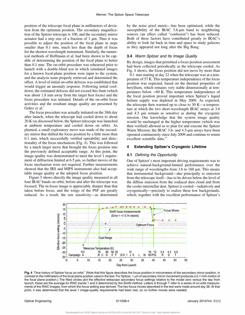
The focus procedure was actually initiated on the 38th dayafter launch, when the telescope had cooled down to about20 K (as discussed below, the Spitzer telescope was launchedat ambient temperature and cooled down on orbit). Asplanned, a small exploratory move was made of the second-ary mirror that shifted the focus position by a little more than0.1 mm, which successfully verified operability and direc-tionality of the focus mechanism (Fig. 4). This was followedby a much larger move that brought the focus position intothe previously defined acceptable range. At this point, theimage quality was demonstrated to meet the level 1 require-ment of diffraction limited at 6.5 μm, so further moves of thefocus mechanism were not required. Further measurementsshowed that the IRS and MIPS instruments also had accep-table image quality at the adopted focus position.
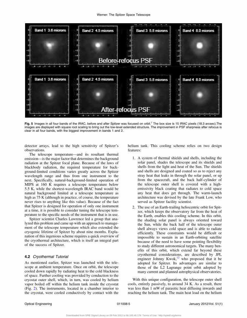
Figure 5 shows directly the image quality measured in allfour IRAC bands on orbit, before and after the telescope wasfocused. The in-focus image is appreciably sharper than thattaken before focus, and the wings of the PSF are greatlyreduced. As a result, the raw sensitivity—as determined
by the noise pixel metric—has been optimized, while thesusceptibility of the IRAC 3.6-μm band to neighboringsources (an effect called “confusion”) has been reduced.Both of these factors have contributed greatly to IRAC’sability to look far back in time and space to study galaxiesas they appeared not long after the Big Bang.
3.4 Warm Spitzer and Its Image Quality
By design, images that permitted a focus position assessmenthad been collected periodically as the telescope cooled. AsFig. 4 shows, the focus position did not move by more than�0.1 mm starting at day 22 when the telescope was at a tem-perature of 57 K. This temperature independence of the focusposition was expected, based on the thermal properties ofberyllium, which remains very stable dimensionally at tem-peratures below ∼60 K. This temperature independence ofthe focal position proved important when Spitzer’s liquidhelium supply was depleted in May 2009. As expected,the telescope then warmed up to close to 30 K—a tempera-ture at which the two short-wavelength IRAC arrays at 3.6and 4.5 μm remain as sensitive as during the cryogenicmission. Our knowledge that the system image qualitywould be unchanged at the higher temperature (which wasthen verified) allowed us to plan for and execute the SpitzerWarm Mission; the IRAC 3.6- and 4.5-μm arrays have beenoperated continuously since July 2009 and continue to returnexcellent scientific data.11
4 Extending Spitzer’s Cryogenic Lifetime
4.1 Defining the Opportunity
One of Spitzer’s most important driving requirements was toachieve natural-background-limited performance over thewide range of wavelengths from 3.6 to 160 μm. This meansthat instrumental background—due principally to emissionfrom the telescope itself—has to be driven below the level ofthe diffuse emission from the zodiacal dust cloud and fromthe cooler interstellar dust. Spitzer is cooled—radiatively andcryogenically—precisely to realize these low backgrounds,which, together with the excellent performance of Spitzer’s
Fig. 4 Time history of Spitzer focus on-orbit.7 (Note that this figure describes the focus position in micrometers of the secondary mirror position, incontrast to the millimeters of the focal plane position used in the text. For Spitzer, 1 μm of secondary mirror movement produces a 0.1-mmmotion ofthe focal plane position.) The filled circles plot the effective telescope secondary focus settings relative to the model zero versus the day fromlaunch; these are the average for IRAC bands 1 and 2 determined by the Simfit method. Letters A through T refer to a series of on-orbit measure-ments of the IRAC images, from which the focus setting was derived. The two focus moves described in the text were made around day 38. At thatpoint, it was determined that the level 1 image-quality requirements had been met, so no further moves were needed.
Werner: The Spitzer Space Telescope
Optical Engineering 011008-4 January 2012/Vol. 51(1)
Downloaded from SPIE Digital Library on 09 Feb 2012 to 66.165.46.178. Terms of Use: http://spiedl.org/terms
detector arrays, lead to the high sensitivity of Spitzer’sobservations.
The telescope temperature—and its resultant thermalemission—is the major factor that determines the backgroundradiation at the Spitzer focal plane. Because of the laws ofblackbody radiation, the required temperature for back-ground-limited conditions varies greatly across the Spitzerwavelength range and thus from one instrument to thenext. Specifically, natural-background-limited operation ofMIPS at 160 K requires a telescope temperature below5.5 K, while the shortest-wavelength IRAC band would benatural background limited at a telescope temperature ashigh as 75 K (although in practice, of course, the temperaturenever rises to anything like this value). Because of the factthat Spitzer is designed for operation of only one instrumentat a time, it is possible to consider tuning the telescope tem-perature to the specific needs of the instrument that is in use.
Spitzer scientist Charles Lawrence led a group that ana-lyzed this problem and came up with an approach to manage-ment of the telescope temperature which also extended thecryogenic lifetime of Spitzer by about nine months. Expla-nation of this ingenious scheme requires a quick overview ofthe cryothermal architecture, which is itself an integral partof the success of Spitzer.
4.2 Cryothermal Tutorial
As mentioned earlier, Spitzer was launched with the tele-scope at ambient temperature. Once on orbit, the telescopecooled down rapidly by radiating heat to the cold blacknessof space. Further cooling was provided by conduction to thecryostat outer shell, which, in turn, was cooled by heliumvapor boiled off within the helium tank inside the cryostat(Fig. 2). The instruments, located in a chamber interior tothe cryostat, were cooled conductively by contact with the
helium tank. This cooling scheme relies on two designfeatures:
1. A system of thermal shields and shells, including thesolar panel, shades the telescope and its shields andshells from the light and heat of the Sun. The shieldsand shells are designed and coated so as to reject anystray heat that leaks in through the solar panel, or upfrom the spacecraft, and the back half-cylinder ofthe telescope outer shell is covered with a high-emissivity black coating that radiates to cold spaceany heat that does get through. The warm-launcharchitecture was devised by the late Frank Low, whoserved as Spitzer facility scientist.
2. The use of an Earth-trailing heliocentric orbit for Spit-zer, which keeps the observatory far from the heat ofthe Earth, enables this cooling scheme. In this orbit,the shading solar panel is always oriented towardthe Sun, while the back half of the telescope outershell always views cold space and is able to radiateefficiently. These constraints would be difficult orimpossible to sustain in an Earth-orbiting satellitebecause of the need to have some pointing flexibilityto study different astronomical targets. The many ben-efits of this orbit, which extend far beyond thesecryothermal considerations, are described by JPLengineer Johnny Kwok,12 who proposed that it beadopted for Spitzer. Its advantages are similar tothose of the L2 Lagrange point orbit adopted bymany current and planned astrophysical observatories.
With this unique configuration, the telescope outer shellcools, entirely passively, to around 34 K. As a result, therewas less than 1 mW of parasitic heat diffusing inwards andreaching the helium tank. The main heat load on the helium
Fig. 5 Images in all four bands of the IRAC, before and after Spitzer was focused on orbit.7 The box size is 15 IRAC pixels (18.3 arcsec).Theimages are displayed with square root scaling to bring out the low-level extended structure. The improvement in PSF sharpness after refocus isclear in all four bands, with the biggest improvement in bands 1 and 2.
Werner: The Spitzer Space Telescope
Optical Engineering 011008-5 January 2012/Vol. 51(1)
Downloaded from SPIE Digital Library on 09 Feb 2012 to 66.165.46.178. Terms of Use: http://spiedl.org/terms
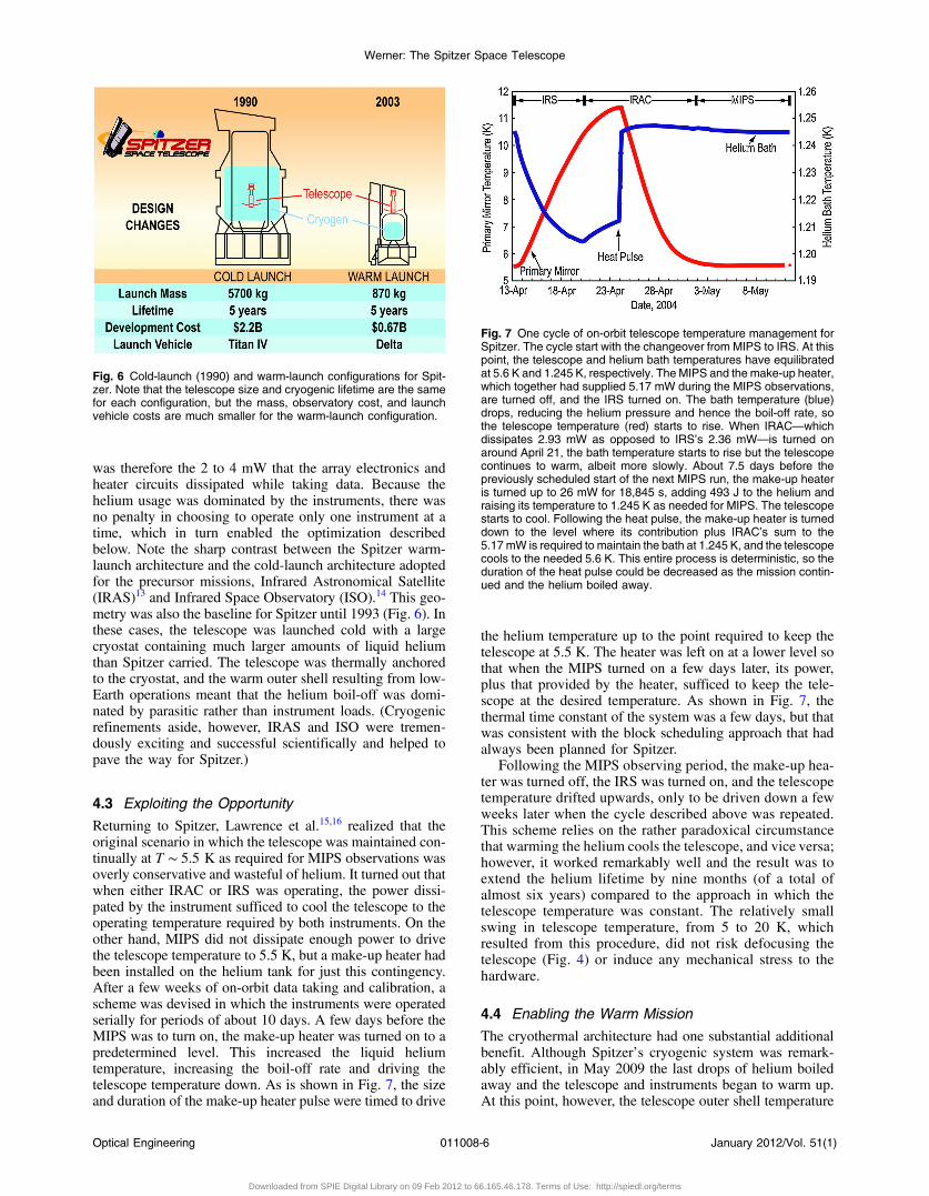
was therefore the 2 to 4 mW that the array electronics andheater circuits dissipated while taking data. Because thehelium usage was dominated by the instruments, there wasno penalty in choosing to operate only one instrument at atime, which in turn enabled the optimization describedbelow. Note the sharp contrast between the Spitzer warm-launch architecture and the cold-launch architecture adoptedfor the precursor missions, Infrared Astronomical Satellite(IRAS)13 and Infrared Space Observatory (ISO).14 This geo-metry was also the baseline for Spitzer until 1993 (Fig. 6). Inthese cases, the telescope was launched cold with a largecryostat containing much larger amounts of liquid heliumthan Spitzer carried. The telescope was thermally anchoredto the cryostat, and the warm outer shell resulting from low-Earth operations meant that the helium boil-off was domi-nated by parasitic rather than instrument loads. (Cryogenicrefinements aside, however, IRAS and ISO were tremen-dously exciting and successful scientifically and helped topave the way for Spitzer.)
4.3 Exploiting the Opportunity
Returning to Spitzer, Lawrence et al.15,16 realized that theoriginal scenario in which the telescope was maintained con-tinually at T ∼ 5.5 K as required for MIPS observations wasoverly conservative and wasteful of helium. It turned out thatwhen either IRAC or IRS was operating, the power dissi-pated by the instrument sufficed to cool the telescope to theoperating temperature required by both instruments. On theother hand, MIPS did not dissipate enough power to drivethe telescope temperature to 5.5 K, but a make-up heater hadbeen installed on the helium tank for just this contingency.After a few weeks of on-orbit data taking and calibration, ascheme was devised in which the instruments were operatedserially for periods of about 10 days. A few days before theMIPS was to turn on, the make-up heater was turned on to apredetermined level. This increased the liquid heliumtemperature, increasing the boil-off rate and driving thetelescope temperature down. As is shown in Fig. 7, the sizeand duration of the make-up heater pulse were timed to drive
the helium temperature up to the point required to keep thetelescope at 5.5 K. The heater was left on at a lower level sothat when the MIPS turned on a few days later, its power,plus that provided by the heater, sufficed to keep the tele-scope at the desired temperature. As shown in Fig. 7, thethermal time constant of the system was a few days, but thatwas consistent with the block scheduling approach that hadalways been planned for Spitzer.
Following the MIPS observing period, the make-up hea-ter was turned off, the IRS was turned on, and the telescopetemperature drifted upwards, only to be driven down a fewweeks later when the cycle described above was repeated.This scheme relies on the rather paradoxical circumstancethat warming the helium cools the telescope, and vice versa;however, it worked remarkably well and the result was toextend the helium lifetime by nine months (of a total ofalmost six years) compared to the approach in which thetelescope temperature was constant. The relatively smallswing in telescope temperature, from 5 to 20 K, whichresulted from this procedure, did not risk defocusing thetelescope (Fig. 4) or induce any mechanical stress to thehardware.
4.4 Enabling the Warm Mission
The cryothermal architecture had one substantial additionalbenefit. Although Spitzer’s cryogenic system was remark-ably efficient, in May 2009 the last drops of helium boiledaway and the telescope and instruments began to warm up.At this point, however, the telescope outer shell temperature
Fig. 6 Cold-launch (1990) and warm-launch configurations for Spit-zer. Note that the telescope size and cryogenic lifetime are the samefor each configuration, but the mass, observatory cost, and launchvehicle costs are much smaller for the warm-launch configuration.
Fig. 7 One cycle of on-orbit telescope temperature management forSpitzer. The cycle start with the changeover from MIPS to IRS. At thispoint, the telescope and helium bath temperatures have equilibratedat 5.6 K and 1.245 K, respectively. The MIPS and the make-up heater,which together had supplied 5.17 mW during the MIPS observations,are turned off, and the IRS turned on. The bath temperature (blue)drops, reducing the helium pressure and hence the boil-off rate, sothe telescope temperature (red) starts to rise. When IRAC—whichdissipates 2.93 mW as opposed to IRS’s 2.36 mW—is turned onaround April 21, the bath temperature starts to rise but the telescopecontinues to warm, albeit more slowly. About 7.5 days before thepreviously scheduled start of the next MIPS run, the make-up heateris turned up to 26 mW for 18,845 s, adding 493 J to the helium andraising its temperature to 1.245 K as needed for MIPS. The telescopestarts to cool. Following the heat pulse, the make-up heater is turneddown to the level where its contribution plus IRAC’s sum to the5.17 mW is required to maintain the bath at 1.245 K, and the telescopecools to the needed 5.6 K. This entire process is deterministic, so theduration of the heat pulse could be decreased as the mission contin-ued and the helium boiled away.
Werner: The Spitzer Space Telescope
Optical Engineering 011008-6 January 2012/Vol. 51(1)
Downloaded from SPIE Digital Library on 09 Feb 2012 to 66.165.46.178. Terms of Use: http://spiedl.org/terms
was still maintained at 34 K, as described above. The tele-scope itself and the instruments thus warmed up to onlyabout 30 K, as they cooled even below the outer shelltemperature by radiating through the open end of the tele-scope tube. At this temperature, the two shortest wavelengthbands of IRAC, at 3.6 and 4.5 μm, continue to operate withunmodified sensitivity, so the Spitzer warm mission—whichuses only these two arrays—began in July 2009. Scientifi-cally, Spitzer hardly skipped a beat, and the scientific returnfrom the warm mission continues to advance our understand-ing of objects ranging from near-Earth asteroids to the mostdistant galaxies.
5 ConclusionsThe scientific progression of infrared space observatories,from IRAS to ISO to Spitzer, is self-evident. Less obviousand equally important is the progression in technology,including cryogenics, optics, and detectors. The successormission to Spitzer will be the James Webb Space Telescope(JWST),17 to be launched toward the end of this decade.JWST will inherit from Spitzer a rich inventory of newlyposed scientific questions. JWST’s ability to go beyond Spit-zer in addressing these questions reflects the fact that it hasleveraged Spitzer’s accomplishments in beryllium optics,radiative cooling, and detector arrays, and advanced the stateof the art in these and other essential technologies.
AcknowledgmentsPortions of the research described here were carried out at theJet Propulsion Laboratory, operated by the California Insti-tute of Technology under contract to NASA (copyright 2011California Institute of Technology). Government sponsor-ship is acknowledged.
References
1. R. D. Gehrz et al., “The NASA Spitzer Space Telescope,” Rev. Sci. Inst.78, 011302 (2007).
2. M. Werner, “A short and personal history of the Spitzer SpaceTelescope,” Astron. Soc. Pac. Conf. Ser. 357, 7–18 (2006).
3. G. Rieke, The Last of the Great Observatories: Spitzer and the Era ofFaster, Better, Cheaper at NASA, University of Arizona Press, Tucson,AZ (2006).
4. M. Werner et al., “First fruits of the Spitzer Space Telescope: galacticand solar system studies,” Ann. Rev. Astron. Astrophys. 44, 269–321(2006).
5. B. T. Soifer, G. Helou, and M. Werner, “The Spitzer view of theextragalactic universe,” Ann. Rev. Astron. Astrophys. 46, 201–240(2008).
6. Reionization to Exoplanets: Spitzer’s Growing Legacy, http://irsa.ipac.caltech.edu/data/SPITZER/docs/spitzermission/reportsandproceedings/meetings/spitzer2009/, Pasadena, CA, (26–28 October 2009).
7. R. Gehrz et al., “The state of the focus and image quality of the SpitzerSpace Telescope as measured in orbit,” Proc. SPIE 5487, 166–176(2004).
8. W. F. Hoffmann et al., “Simfit and focus diversity: methods fordetermining the focus of the SIRTF telescope in space without afocus slew,” Proc. SPIE 4850, 428–440 (2003).
9. W. F. Hoffmann et al., “Determination of Spitzer Space Telescope focusfrom IRAC images without a focus slew,” Proc. SPIE 5487, 186–200(2004).
10. E. L. Wright, “On using a space telescope to detect faint galaxies,” Pub.Astron. Soc. Pacific 97, 451–453 (1985).
11. S. J. Carey et al., “Calibration and data quality of warm IRAC,” Proc.SPIE 7731, 77310N (2010).
12. J. H. Kwok et al., “Spitzer Space Telescope mission design,” Proc. SPIE5487, 201–210 (2004).
13. G. Neugebauer, “The Infrared Astronomical Satellite (IRAS) mission,”Astrophys. J. 278, L1–L6 (1984).
14. M. F. Kessler et al., “The Infrared Space Observatory (ISO) mission,”Astron. Astrophys. 315, L27–L31 (1996).
15. C. R. Lawrence et al., “Operating Spitzer for maximum lifetime,” Proc.SPIE 4850, 153–161 (2003).
16. C. R. Lawrence and P. T. Finley, “Optimizing cryogen utilization onSpitzer Space Telescope,” Proc. SPIE 5487, 124–133 (2004).
17. J. P. Gardner et al., “The James Webb Space Telescope,” Space Sci. Rev.123, 485–606 (2006).
Michael Werner is project scientist for theSpitzer Space Telescope and also chiefscientist for astronomy and physics at theJet Propulsion Laboratory, California Instituteof Technology. He holds an undergraduatedegree in physics from Haverford Collegeand a PhD in astronomy from Cornell Univer-sity. He has received numerous awards forhis work on Spitzer, including the GeorgeDarwin lectureship of the Royal AstronomicalSociety and NASA’s Distinguished Public
Service Medal.
Werner: The Spitzer Space Telescope
Optical Engineering 011008-7 January 2012/Vol. 51(1)
Downloaded from SPIE Digital Library on 09 Feb 2012 to 66.165.46.178. Terms of Use: http://spiedl.org/terms


![Volume 5487 Optical, Infrared, and Millimeter Space Telescopes · An integrated optimal estimation approach to Spitzer Space Telescope focal plane survey [5487-84] D. Bayard, B. Kang,](https://static.fdocuments.net/doc/165x107/5f7bb87dfb9ada3c7361f7af/volume-5487-optical-infrared-and-millimeter-space-an-integrated-optimal-estimation.jpg)


![Index [iasgatewayy.com] · 2020. 2. 19. · 6. Vyom Mitra 66 7. Anti-Satellite Missile (ASAT) 67 8. Stem Cell Banking 68 9. Spitzer Space Telescope 68 10. Daniel K Inouye Solar Telescope](https://static.fdocuments.net/doc/165x107/60ccc088d4fd542d3c787087/index-2020-2-19-6-vyom-mitra-66-7-anti-satellite-missile-asat-67-8.jpg)