The Spartan-3E Tutorial 2: Introduction to using the...
83
Tutorial 2: Introduction to Using the PicoBlaze Microcontroller 1 Xilinx Spartan-3E Project Navigator Version 14.3 The Spartan-3E Tutorial 2: Introduction to using the PicoBlaze Microcontroller Version 1.0 Author: Jasmine Banks © 2012, Queensland University of Technology
Transcript of The Spartan-3E Tutorial 2: Introduction to using the...

Tutorial 2: Introduction to Using the PicoBlaze Microcontroller 1
Xilinx Spartan-3E Project Navigator Version 14.3
The Spartan-3E Tutorial 2:
Introduction to using the PicoBlaze Microcontroller
Version 1.0
Author: Jasmine Banks
© 2012, Queensland University of Technology

Tutorial 2: Introduction to Using the PicoBlaze Microcontroller 2
Xilinx Spartan-3E Project Navigator Version 14.3

Tutorial 2: Introduction to Using the PicoBlaze Microcontroller 3
Xilinx Spartan-3E Project Navigator Version 14.3
Acknowledgements
Parts of this tutorial are based on an earlier version written for Project Navigator version 9.2, written by Michael Bakker, Matthew Grace and Warwick Kilroy, as part of ENB345 – Advanced Design in 2008.

Tutorial 2: Introduction to Using the PicoBlaze Microcontroller 4
Xilinx Spartan-3E Project Navigator Version 14.3

Tutorial 2: Introduction to Using the PicoBlaze Microcontroller 5
Xilinx Spartan-3E Project Navigator Version 14.3
Glossary
ALU
DOS
FPGA
JTAG
LED
KCPSM3
RISC
VHDL
VHSIC
Arithmetic Logic Unit
Disk Operating System
Field Programmable Gate Array
Joint Test Action Group
Light Emitting Diode
(K)Constant Coded Programmable State Machine – a very simple 8-bit microcontroller optimised for Spartan-3 devices [2].
Reduced Instruction Set Computing
VHSIC Hardware Description Language
Very High Speed Integrated Circuit

Tutorial 2: Introduction to Using the PicoBlaze Microcontroller 6
Xilinx Spartan-3E Project Navigator Version 14.3

Tutorial 2: Introduction to Using the PicoBlaze Microcontroller 7
Xilinx Spartan-3E Project Navigator Version 14.3
Table of Contents
Acknowledgements ……………………………………………………….......………………
Glossary ……………………………………………………………………….......………….
List of Figures ……………………………………………………………....…….………….
List of Tables …………………………………………………………………………………
1.0 Introduction ………………………………………………………………....……....……
1.1 Design Functionality ………………………………………………………..………..
1.2 Relevant Documentation ..…………………………….……………………..……….
1.3 Pre-requisite Knowledge ……………………………………………………………..
1.4 Scope ……………………………………………………………………….......….....
2.0 Equipment …………………………………………………………………..................….
3.0 Background – The PicoBlaze Microcontroller …………………………….....…...………
4.0 Procedure Part 1 – PicoBlaze ………………………………………….....…….…………
4.1 PicoBlaze Download ………………………………………….....……………………
4.2 Copy Files …………………………………………………….………………………
4.3 Assembly Language Code …………………………….............………………………
4.4 Running the Assembler …………………………….....………………………………
5.0 Procedure Part 2 – Project Navigator ………………......…………………........…………
5.1 Startup …………………………………………………………………...……....……
5.2 Creating a New Project ……………………………………………………....…....….
5.3 Adding Source Files ………………………………………………………..…............
5.4 tutorial.vhd and kcpsm3.vhd - Observations ……………………....……....………….
5.5 Adding a top_level Entity ………………………………………….....………………
5.6 Editing the top_level Entity …………………………………………….......………...
5.7 top_level.vhd – Code …………………………………….......……………….............
5.8 Syntax Checking ………………………………………………...……………………
5.9 Pin Assignment ………………………………………………….....…………………
5.10 Synthesize, Translate, Map and Place & Route ……........………..……....…………
5.11 Download Design to Board ………………………………………..………...………
6.0 Running the Program on the Spartan-3E Board …………………………..………………
7.0 Further Information ………………………………………………………......……………
8.0 References ………………………………………………………………...……....………
Appendix A – top_level.vhd ……………………………………………………......…………
page
3
5
9
13
15
15
15
15
15
17
19
21
21
21
22
23
31
31
32
35
38
40
45
49
52
54
59
61
75
77
79
81

Tutorial 2: Introduction to Using the PicoBlaze Microcontroller 8
Xilinx Spartan-3E Project Navigator Version 14.3

Tutorial 2: Introduction to Using the PicoBlaze Microcontroller 9
Xilinx Spartan-3E Project Navigator Version 14.3
List of Figures
Figure 2.1: Spartan-3E Development Board …………………………………….....................
Figure 3.1: PicoBlaze components …………………………………….................……….......
Figure 3.2: KCPSM3 component declaration ………………………………….…………......
Figure 3.3: Block Memory component declaration ……………….……………......................
Figure 4.1: KCPSM3 files after unzipping ……………...……….............................................
Figure 4.2: Simple PicoBlaze program .….……. ……………….............................................
Figure 4.3: Files in the working directory ……………...………..……………………............
Figure 4.4: KCPSM3 assembler files …………………………………..………......................
Figure 4.5: DOS Command Prompt window, after changing to working directory …….........
Figure 4.6: DOS Command Prompt window, with KCPSM3 command typed in ……...........
Figure 4.7: DOS Command Prompt window, after KCPSM3 successfully run ………….......
Figure 4.8: Error message which appears if KCPSM3 is run on a 64-bit machine …...............
Figure 4.9: DOSBox window …................................................................................................
Figure 4.10: DOSBox window, with KCPSM3 command typed in …..…................................
Figure 4.11: DOSBox window, after KCPSM3 successfully run …………….........................
Figure 4.12: Files in the working directory after KCPSM3 successfully run …………….......
Figure 5.1: Project Navigator Software Startup Window …….................................................
Figure 5.2: New Project Wizard, Create New Project Page ………….……….........................
Figure 5.3: New Project Wizard, Project Settings Page ……………………………................
Figure 5.4: New Project Wizard, Project Summary Page ……………………………….........
Figure 5.5: Adding a source file to the project …………..…....................................................
Figure 5.6: Add Source file selection window ..........................................................................
Figure 5.7: Adding Source Files window …………..................................................................
Figure 5.8: kcpsm3 and tutorial in the Sources window …………...........................................
page
17
19
20
20
21
22
22
23
23
24
24
25
26
27
28
29
31
32
33
34
35
36
36
37

Tutorial 2: Introduction to Using the PicoBlaze Microcontroller 10
Xilinx Spartan-3E Project Navigator Version 14.3
Figure 5.9: Source code for tutorial.vhd displayed in a tab ………...........................................
Figure 5.10: tutorial entity .....…................................................................................................
Figure 5.11: kcpsm3 entity .……………………………………………....................…......….
Figure 5.12: Adding a source file to the project …………………………………..……......…
Figure 5.13: New Source Wizard, Select Source Type .............................................................
Figure 5.14: New Source Wizard, Define Module ……………………………………….……
Figure 5.15: New Source Wizard, Summary …….……...….……............................................
Figure 5.16: top_level in the Sources window ………………………………..………………
Figure 5.17: top_level.vhd, as displayed in Project Navigator, before editing ………………..
Figure 5.18(a): Architecture of top_level.vhd, part 1 ………………………………..………..
Figure 5.18(b): Architecture of top_level.vhd, part 2 ………………………………….……..
Figure 5.19: top_level in the Sources window ………………………………………………..
Figure 5.20: Component declarations ........................................................................................
Figure 5.21: Signal declarations ................................................................................................
Figure 5.22: Component instantiations …………………………………………………..……
Figure 5.23: Input ports ..............................................................................................................
Figure 5.24: Output ports ...........................................................................................................
Figure 5.25: Portion of Project Navigator screen with Synthesize – XST expanded ……..…..
Figure 5.26: A green tick next to Check Syntax shows that no errors were found ……….......
Figure 5.27: Example where an error was purposely introduced ………………………………
Figure 5.28: Portion of Project Navigator screen, with User Constraints expanded ………….
Figure 5.29: Dialog Box asking if you wish to create an Implementation Constraint File .….
Figure 5.30: Initial appearance of PlanAhead window ……………………………………….
Figure 5.31: I/O Ports displayed in a separate window ……………………………………….
38
38
39
40
41
42
43
44
45
46
47
48
49
50
50
51
51
52
53
53
55
55
56
56

Tutorial 2: Introduction to Using the PicoBlaze Microcontroller 11
Xilinx Spartan-3E Project Navigator Version 14.3
Figure 5.32: I/O Ports window with individual ports expanded ……..................................….
Figure 5.33: I/O Ports window with values filled in ………………………………………….
Figure 5.34: Portion of Project Navigator screen, with Implement Design expanded ………..
Figure 5.35: Portion of Project Navigator screen, after Translate, Map and Place & Route have successfully been run ………………………….……..
Figure 5.36: Portion of Project Navigator screen, with Implement Design expanded …..……
Figure 5.37: Portion of Project Navigator screen, after Generate Programming File has successfully been run …………………………………………….…….
Figure 5.38: The initial iMPACT window ………………………………………………..…..
Figure 5.39: iMPACT window, after double-clicking on Boundary Scan …………………….
Figure 5.40: iMPACT window, showing Initialize Chain selected ……………………………
Figure 5.41: iMPACT window, assign configuration files ………………………………..…..
Figure 5.42: iMPACT window, assigning the configuration file for the xc3e500e ……….…..
Figure 5.43: iMPACT window, dialog box asking if we wish to attach an SPI or BPI PROM .
Figure 5.44: : iMPACT window, bypassing the xcf04s ………………………….……………
Figure 5.45: iMPACT window, bypassing the xc2c64a …………………………….………..
Figure 5.46: iMPACT window, Device Programming Properties dialog box ...........................
Figure 5.47: iMPACT window, showing the device chain …………………………..………..
Figure 5.48: iMPACT window, options which appear when right clicking on the xc3s500e ..
Figure 5.49: iMPACT window, after the program has been successfully downloaded to the Spartan-3E board …………………………………………..………
Figure 6.1: The Spartan-3E board with the program running ………………..........…...……..
57
58
59
60
61
62
63
64
65
66
67
68
69
70
71
72
72
73
75

Tutorial 2: Introduction to Using the PicoBlaze Microcontroller 12
Xilinx Spartan-3E Project Navigator Version 14.3

Tutorial 2: Introduction to Using the PicoBlaze Microcontroller 13
Xilinx Spartan-3E Project Navigator Version 14.3
List of Tables
Table 5.1: Input/output ports of the top_level entity .……………………………..…......……
Table 5.2: Values to enter in the I/O Ports window ……………………….………...…....…...
Page
54
57

Tutorial 2: Introduction to Using the PicoBlaze Microcontroller 14
Xilinx Spartan-3E Project Navigator Version 14.3

Tutorial 2: Introduction to Using the PicoBlaze Microcontroller 15
Xilinx Spartan-3E Project Navigator Version 14.3
1.0 Introduction
This tutorial is designed to help new users become familiar with using the PicoBlaze microcontroller with the Spartan-3E board. The tutorial gives a brief introduction to the PicoBlaze microcontroller, and then steps through the following:
• Writing a small PicoBlaze assembly language (.psm) file, and stepping through the process of assembling the .psm file using KCPSM3.
• Writing a top level VHDL module to connect the PicoBlaze microcontroller (KCPSM3 component) and the program ROM, and to connect the required input and output ports.
• Connecting the top level module inputs and outputs to the switches, buttons and LEDs on the Spartan-3E board.
• Downloading the program to the Spartan-3E board using the Project Navigator software.
1.1 Design Functionality
The code written in this tutorial reads the values of the four switches and the four push buttons, and displays the current values on the eight LEDS.
1.2 Relevant Documentation
Before commencing this tutorial, it would be helpful to download the Spartan-3E FPGA Starter Kit Board User Guide [1], and the PicoBlaze 8-bit Embedded Microcontroller User Guide [2].
1.3 Pre-requisite Knowledge
Before commencing this tutorial, the user should work through “The Spartan-3E Tutorial 1: Introduction to FGPA Programming” [3].
1.4 Scope
This tutorial is designed to help the user who is just starting to “get into” using the PicoBlaze with the Spartan-3E. It steps through the process of creating a very simple PicoBlaze program, running the assembler, putting the VHDL components together in Project Navigator, and downloading the final program to the board. It is not designed to be a tutorial on VHDL syntax or to provide detailed information on the PicoBlaze. For help with VHDL, the user can consult with a number of textbooks on the subject, such as [4,5], or find help online. The book by Chu [6] is also a useful reference for the Spartan-3 with many useful examples. Reference designs for the Spartan-3E can also be found here [7]. For detailed information about the features and instruction set of the PicoBlaze, the user can consult the documentation in [2,8].

Tutorial 2: Introduction to Using the PicoBlaze Microcontroller 16
Xilinx Spartan-3E Project Navigator Version 14.3

Tutorial 2: Introduction to Using the PicoBlaze Microcontroller 17
Xilinx Spartan-3E Project Navigator Version 14.3
2.0 Equipment
The following are required to work through this tutorial:
• The Xilinx ISE Project Navigator software. Version 14.3 was used in this tutorial, but older versions of the software can be used. The software can be downloaded with a free WebPack license from the Xilinx website, http://www.xilinx.com/. The user will need to register and log in.
• The Spartan-3E Starter Kit, including the Spartan-3E development board, power cable and USB cable for PC connection. The Spartan-3E development board is shown in Figure 2.1.
• The Picoblaze 8-bit Microcontroller software. The software can be downloaded for free from the Xilinx website, http://www.xilinx.com/. Again the user will need to register and log in.
• If a 64-bit machine is being used, software which can run 32-bit DOS programs, such as DOSBox, will be needed to run the KCPSM3 executable. DOSBox can be downloaded from http://www.dosbox.com/.
Figure 2.1: Spartan-3E Development Board.
Reset
Button
ON/OFF
FPGA
JTAG
LEDs
SW0-3
Push
Buttons
LCD
USB
Power

Tutorial 2: Introduction to Using the PicoBlaze Microcontroller 18
Xilinx Spartan-3E Project Navigator Version 14.3
3.0 Background – The PicoBlaze Micocontroller
The PicoBlaze is an 8-bit RISC microcontroller which is specifically designed and optimized for the Spartan-3 family. One of its main advantages is its small size, requiring only 96 FPGA slices. It is provided as a free, source-level VHDL file with royalty-free re-use within Xilinx FPGAs [2].
Figure 3.1 shows that the PicoBlaze consists of two components. The KCPSM3 component provides the ALU, registers, scratchpad RAM etc. The Block Memory (Program) component stores the instructions to be executed. This typically consists of a Block RAM, of 1024 bytes in size.
Figure 3.1: PicoBlaze components [8].
The basic design process using the PicoBlaze follows the steps below:
1. A PicoBlaze program is written in assembly language. This file is given the extension .psm.
2. The KCPSM3 assembler is run on the .psm file, and a VHDL file (extension .vhd) which embeds the instructions in the Block Memory component, is output. The name of the .vhd file will be derived from the name of the .psm file, i.e., if the .psm file is myprog.psm, then the .vhd file will be myprog.vhd.
3. The VHDL code for the Block Memory and KCPSM3 modules is loaded into Project Navigator. Further VHDL code will need to be written to connect the two modules and interface to the outside world.
4. The project is compiled using the Project Navigator Software, and ultimately downloaded to the Spartan-3E board (or other target hardware).
Figures 3.2 and 3.3 show the VHDL component declarations for the KCPSM3 and Block Memory respectively. Note that the name of the Block Memory component is derived from the name of the original .psm file, i.e., if the .psm file was myprog.psm, the Block Memory component will be called myprog.

Tutorial 2: Introduction to Using the PicoBlaze Microcontroller 19
Xilinx Spartan-3E Project Navigator Version 14.3
Figure 3.2: KCPSM3 component declaration.
Figure 3.3: Block Memory component declarations.
In addition, it is possible to download a new program into the Block Memory, using the JTAG port on the Spartan-3E board. This can provide a convenient means to update the program without having to recompile the VHDL code in Project Navigator. This is not covered by this introductory tutorial, and the user can refer to documentation such as [3] for more information.
component myprog port (address : in std_logic_vector(9 downto 0); instruction : out std_logic_vector(17 downt o 0); clk : in std_logic); end component;
component kcpsm3 port (address : out std_logic_vector(9 down to 0); instruction : in std_logic_vector(17 down to 0); port_id : out std_logic_vector(7 downto 0) ; write_strobe : out std_logic; out_port : out std_logic_vector(7 downto 0) ; read_strobe : out std_logic; in_port : in std_logic_vector(7 downto 0); interrupt : in std_logic; interrupt_ack : out std_logic; reset : in std_logic; clk : in std_logic); end component;
Name of component derived
from name of .psm file

Tutorial 2: Introduction to Using the PicoBlaze Microcontroller 20
Xilinx Spartan-3E Project Navigator Version 14.3
4.0 Procedure Part 1 – PicoBlaze
4.1 PicoBlaze Download
1. Download the file KCPSM3.zip from http://www.xilinx.com/. The version of the software for the Spartan-3 family should be chosen.
2. Unzip the file. After unzipping, the files should appear as shown in Figure 4.1.
Figure 4.1: KCPSM3 files after unzipping.
The file KCPSM3_Manual.pdf is listed as reference [8] in this tutorial.
4.2 Copy Files
1. Create a directory called tutorial_2 in an appropriate location. This will be the working directory for the rest of this tutorial.
2. Copy the following files in the Assembler directory into tutorial_2 :
• KCPSM3.EXE • ROM_form.coe • ROM_form.v
• ROM_form.vhd
3. Copy the following file in the VHDL directory into tutorial_2 :
• kcpsm3.vhd

Tutorial 2: Introduction to Using the PicoBlaze Microcontroller 21
Xilinx Spartan-3E Project Navigator Version 14.3
4.3 Assembly Language Code
1. Open a text editor (for example, Notepad or Wordpad), and enter the text shown in Figure 4.2. The text consists of a very simple program written in the KCPSM3 assembly language.
The program runs in an infinite loop, reading the contents of an input port at address 00h (connected to the switches) into a register, and writing the contents of this register to an output port at address 80h (connected to the LEDs). Characters which appear after a “;” in each line are comments.
Figure 4.2: Simple PicoBlaze program.
2. Save your file to tutorial.psm , in the tutorial_2 directory. If using Notepad, be careful not to save the file as tutorial.psm.txt. The name of the file should be restricted to 8 characters. The tutorial_2 directory should now contain the files shown in Figure 4.3.
Figure 4.3: Files in the tutorial_2 working directory.
; Simple loop that puts contents of input register ; into the output register ; ; switches DSIN $00 ; LEDS DSOUT $80 start: INPUT s0, 00 ; read switches into registe r s0 OUTPUT s0, 80 ; write contents of s0 to ou tput port 80 - leds. JUMP start ; loop back to start

Tutorial 2: Introduction to Using the PicoBlaze Microcontroller 22
Xilinx Spartan-3E Project Navigator Version 14.3
4.4 Running the Assembler
As shown in Figure 4.4, the assembler takes the .psm file as input, as well as three Block RAM initialisation templates. Fifteen different output files are produced. In this tutorial, we will be using the .vhd output file.
Figure 4.4: KCPSM3 assembler files [2].
The assembler is a DOS executable file, KCPSM3.exe, which can be run in a DOS Command Prompt window.
4.4.1 32-bit Operating Systems
1. Open a DOS Command Prompt window by selecting:
Start→→→→All Programs→→→→Accessories→→→→Command Prompt
2. Use the cd command to change into the tutorial_2 working directory, as shown in Figure 4.5.
Figure 4.5: DOS Command Prompt window, after changing to working directory.
Tutorial 2: Introduction to Using the PicoBlaze Microcontroller 23
Xilinx Spartan-3E Project Navigator Version 14.3
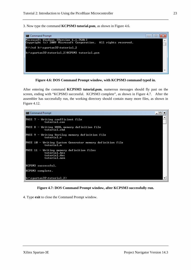
3. Now type the command KCPSM3 tutorial.psm, as shown in Figure 4.6.
Figure 4.6: DOS Command Prompt window, with KCPSM3 command typed in.
After entering the command KCPSM3 tutorial.psm, numerous messages should fly past on the screen, ending with “KCPSM3 successful. KCPSM3 complete”, as shown in Figure 4.7. After the assembler has successfully run, the working directory should contain many more files, as shown in Figure 4.12.
Figure 4.7: DOS Command Prompt window, after KCPSM3 successfully run.
4. Type exit to close the Command Prompt window.

Tutorial 2: Introduction to Using the PicoBlaze Microcontroller 24
Xilinx Spartan-3E Project Navigator Version 14.3
4.4.2 64-bit Operating Systems
The KCPSM3 executable will only work on 32-bit operating systems. If you are using a 64-bit machine and attempt to run KCPMS3 in a DOS Command Prompt window, the error message shown in Figure 4.8 will appear.
Figure 4.8: Error message which appears if it is attempted to run KCPSM3 on a 64-bit machine.
One way to work around this and run KCPSM3 is to use the DOSbox software, which can be downloaded from http://www.dosbox.com/.
1. Download and run DOSBox.
2. Mount the working directory and change into this directory. When DOSbox is started up, a command window which resembles the DOS Command Prompt window appears. However, it is first necessary to mount the working directory to a drive letter before being able to enter this directory and run programs. This is done with the mount command:
mount <drive_letter> <directory>
Figure 4.9 shows the commands entered to mount and change into the working directory. In this case, the working directory is mounted as drive letter c. The command c: is then used to change into this directory.

Tutorial 2: Introduction to Using the PicoBlaze Microcontroller 25
Xilinx Spartan-3E Project Navigator Version 14.3
Figure 4.9: DOSBox window, commands entered to mount and change into the working directory.
3. Now type the command KCPSM3 tutorial.psm, as shown in Figure 4.10.

Tutorial 2: Introduction to Using the PicoBlaze Microcontroller 26
Xilinx Spartan-3E Project Navigator Version 14.3
Figure 4.10: DOSBox window, with KCPSM3 command typed in.
After entering the command KCPSM3 tutorial.psm, numerous messages should fly past on the screen, ending with “KCPSM3 successful. KCPSM3 complete”, as shown in Figure 4.11. After the assembler has successfully run, the working directory should contain many more files, as shown in Figure 4.12.

Tutorial 2: Introduction to Using the PicoBlaze Microcontroller 27
Xilinx Spartan-3E Project Navigator Version 14.3
Figure 4.11: DOSBox window, after KCPSM3 successfully run.
4. Type exit to close DOSBox.

Tutorial 2: Introduction to Using the PicoBlaze Microcontroller 28
Xilinx Spartan-3E Project Navigator Version 14.3
Figure 4.12: Files in the working directory after KCPSM3 successfully run.

Tutorial 2: Introduction to Using the PicoBlaze Microcontroller 29
Xilinx Spartan-3E Project Navigator Version 14.3

Tutorial 2: Introduction to Using the PicoBlaze Microcontroller 30
Xilinx Spartan-3E Project Navigator Version 14.3
5.0 Procedure Part 2 – Project Navigator
5.1 Startup
Start the Project Navigator software by selecting:
Start→→→→All Programs→→→→XILINX Design Tools→→→→Xilinx ISE Design Suite 14.3→→→→ISE Design Tools→→→→32 bit Project Navigator
or
Start→→→→All Programs→→→→XILINX Design Tools→→→→Xilinx ISE Design Suite 14.3→→→→ISE Design Tools→→→→64 bit Project Navigator
depending on your system. The Xilinx Project Navigator software should start. The initial window which appears on startup should appear as shown in Figure 5.1.
Figure 5.1: Project Navigator Software Startup Window.

Tutorial 2: Introduction to Using the PicoBlaze Microcontroller 31
Xilinx Spartan-3E Project Navigator Version 14.3
5.2 Creating a New Project
1. Select File→→→→New Project. The New Project Wizard will appear.
2. Type tutorial_2 in the Name: field.
3. Choose Location: and Working Directory: as the tutorial_2 working directory.
4. Verify that Top-level source type: is selected as HDL .
5. The properties should now be set as shown in Figure 5.2. Click Next to move to the Project Settings page.
Figure 5.2: New Project Wizard, Create New Project Page. 6. Fill in the properties as follows:
• Evaluation Development Board: None Specified or Spartan-3E Starter Board • Product Category: All • Family: Spartan3E • Device: XC3S500E

Tutorial 2: Introduction to Using the PicoBlaze Microcontroller 32
Xilinx Spartan-3E Project Navigator Version 14.3
• Package: FG320 • Speed Grade: -4 • Top-Level Source Type: HDL • Synthesis Tool: XST (VHDL/Verilog) • Simulator: ISim (VHDL/Verilog) • Preferred Language: VHDL • Property Specification in Project File: Store All Values • Manual Compile Order: unchecked • VHDL Source Analysis Standard: VHDL-93 • Enable Message Filtering: unchecked
Note if you choose Evaluation Development Board as Spartan-3E Started Board, properties from Product Category through to Speed will be filled in automatically. However, you must make sure that Preferred Language is set to VHDL. The properties should now be filled in as shown in Figure 5.3.
Figure 5.3: New Project Wizard, Project Settings Page.

Tutorial 2: Introduction to Using the PicoBlaze Microcontroller 33
Xilinx Spartan-3E Project Navigator Version 14.3
7. Click Next to move to the Project Summary page, which will appear as shown in Figure 5.4.
Figure 5.4: New Project Wizard, Project Summary Page.
8. Click Finish to exit the New Project Wizard.

Tutorial 2: Introduction to Using the PicoBlaze Microcontroller 34
Xilinx Spartan-3E Project Navigator Version 14.3
5.3 Adding Source Files
1. Select Project→→→→Add Source as shown in Figure 5.5. A window will appear allowing you to choose one or more files.
Figure 5.5: Adding a source file to the project.
2. Select TUTORIAL.VHD and kcpsm3.vhd as shown in Figure 5.6. Both files can be selected at once by clicking on the first filename, holding down the CTRL key and clicking the second filename. Alternatively, one file can be selected and steps 1-3 repeated for the second file.

Tutorial 2: Introduction to Using the PicoBlaze Microcontroller 35
Xilinx Spartan-3E Project Navigator Version 14.3
Figure 5.6: Add Source file selection window.
3. The Adding Source Files window will now appear as shown in Figure 5.7, showing the two files selected to be added to the project. Click OK.
Figure 5.7: Adding Source Files window.

Tutorial 2: Introduction to Using the PicoBlaze Microcontroller 36
Xilinx Spartan-3E Project Navigator Version 14.3
As shown in Figure 5.8, kcpsm3 and tutorial will now appear in the Sources window. Double-clicking on either filename in the Sources window will display the file in a tab.
Figure 5.8: kcpsm3 and tutorial in the Sources window.
Sources
Window

Tutorial 2: Introduction to Using the PicoBlaze Microcontroller 37
Xilinx Spartan-3E Project Navigator Version 14.3
5.4 tutorial.vhd and kcpsm3.vhd – Observations
1. Double-click on tutorial in the Sources window. This will display the source code in a tab, as shown in Figure 5.9. It can be seen that Project Navigator colour codes the text of VDHL files, to make them easier to read. Comment lines, which start with “- -” are displayed in green. Reserved words of the VHDL language are displayed in blue, while VHDL types are displayed in red. Everything else is left as black.
Figure 5.9: Source code for tutorial.vhd is displayed in a tab.
A close up of the code for the tutorial entity is shown in Figure 4.10. Note that this corresponds to the Block Memory (Program) component of Figures 3.1 and 3.3.
Figure 5.10: tutorial entity.
tutorial in
Sources window Source code for
tutorial.vhd appears
in this tab

Tutorial 2: Introduction to Using the PicoBlaze Microcontroller 38
Xilinx Spartan-3E Project Navigator Version 14.3
2. Double-click on kcpsm3 in the Sources window, to display the source code for kcpsm3.vhd. A close up of the code for the kspsm3 entity is shown in Figure 5.11. Note that this corresponds to the KCPSM3 block of Figures 3.1 and 3.2.
Figure 5.11: kcpsm3 entity.

Tutorial 2: Introduction to Using the PicoBlaze Microcontroller 39
Xilinx Spartan-3E Project Navigator Version 14.3
5.5 Adding a top_level Entity
VHDL code still needs to be written to tie together the kcpsm3 and tutorial entities, and also to interface with the Spartan-3E board. We will create a file called top_level.vhd for this purpose.
1. Select Project→→→→New Source as shown in Figure 5.12. The New Source Wizard will appear.
Figure 5.12: Adding a source file to the project.
2. Select Source Type as VHDL Module .
3. Enter the file name as top_level, and enter the location of the file (same as the project location entered earlier.
4. Verify that the Add to project box is checked. The New Source Wizard should now appear as shown in Figure 5.13.

Tutorial 2: Introduction to Using the PicoBlaze Microcontroller 40
Xilinx Spartan-3E Project Navigator Version 14.3
Figure 5.13: New Source Wizard, Select Source Type.
5. Click Next to go to the Define Module window.
6. Define the ports (inputs and outputs of the design) by entering the information as shown in Figure 5.14. These ports are described as follows:
• switches will be an input consisting of 8 bits, and will be connected with the 4 slide switches and 4 push buttons on the Spartan-3E.
• clk will be an input consisting of 1 bit, and will be connected to the clock input. • LEDs will be an output consisting of 8 bits, and will be connected with the LEDs on the
Spartan-3E.

Tutorial 2: Introduction to Using the PicoBlaze Microcontroller 41
Xilinx Spartan-3E Project Navigator Version 14.3
Figure 5.14: New Source Wizard, Define Module.
7. Click Next to move to the Summary page, as shown in Figure 5.15.

Tutorial 2: Introduction to Using the PicoBlaze Microcontroller 42
Xilinx Spartan-3E Project Navigator Version 14.3
Figure 5.15: New Source Wizard, Summary.
9. Click Finish to exit the New Source Wizard.
As shown in Figure 5.16, top_level will now appear in the Sources window. Double-clicking on top_level in the Sources window will display the file, top_level.vhd in a tab.

Tutorial 2: Introduction to Using the PicoBlaze Microcontroller 43
Xilinx Spartan-3E Project Navigator Version 14.3
Figure 5.16: top_level in the Sources window.
top_level in
Sources window

Tutorial 2: Introduction to Using the PicoBlaze Microcontroller 44
Xilinx Spartan-3E Project Navigator Version 14.3
5.6 Editing the top_level Entity
1. Double-click on top_level in the Sources window to display the file, top_level.vhd in a tab. The code for top_level.vhd is shown in Figure 5.17.
Figure 5.17: top_level.vhd, as displayed in Project Navigator, before editing.
The code in Figure 5.17 contains an entity and an architecture section. The entity section defines the inputs and outputs of this hardware block. In this case these have been automatically added using the New Source Wizard.
The architecture section still needs to be written for this module.
2. Replace the architecture block in Figure 5.17 with the code in Figure 5.18(a) and (b). This code is a trimmed down version of the Initial Design for the Spartan-3E FPGA Starter Kit Board (the original design shipped with the board), downloaded from [7].
For reference the complete code for top_level.vhd is listed in Appendix A. Note that where VDHL code is listed in this tutorial, the same colour coding as Project Navigator is used, to assist with readability.
3. Save the file by selecting File → Save from the main menu.
entity
architecture

Tutorial 2: Introduction to Using the PicoBlaze Microcontroller 45
Xilinx Spartan-3E Project Navigator Version 14.3
Figure 5.18(a): Architecture of top_level.vhd, part 1.
architecture Behavioral of top_level is -- declaration of KCPSM3 (always use this declarati on to call -- up PicoBlaze core) component kcpsm3 port (address : out std_logic_vector (9 downto 0); instruction : in std_logic_vector (17 downto 0); port_id : out std_logic_vector (7 downto 0); write_strobe : out std_logic ; out_port : out std_logic_vector (7 downto 0); read_strobe : out std_logic ; in_port : in std_logic_vector (7 downto 0); interrupt : in std_logic ; interrupt_ack : out std_logic ; reset : in std_logic ; clk : in std_logic ); end component ; --------------------------------------------------- ---------------------- -- declaration of program memory (here you will spe cify the entity name -- as your .psm prefix name) component tutorial port (address : in std_logic_vector (9 downto 0); instruction : out std_logic_vector (17 downto 0); clk : in std_logic ); end component ; --------------------------------------------------- ---------------------- -- Signals used to connect PicoBlaze core to progra m memory and I/O logic signal address : std_logic_vector (9 downto 0); signal instruction : std_logic_vector (17 downto 0); signal port_id : std_logic_vector (7 downto 0); signal out_port : std_logic_vector (7 downto 0); signal in_port : std_logic_vector (7 downto 0); signal write_strobe : std_logic ; signal read_strobe : std_logic ; signal interrupt_ack : std_logic ; signal reset : std_logic ; -- the following input is assigned an inactive valu e since it is -- unused in this example signal interrupt : std_logic :='0'; --------------------------------------------------- ---------------------- -- Start of circuit description begin -- Instantiating the PicoBlaze core processor: kcpsm3 port map (address => address, instruction => instruction, port_id => port_id, write_strobe => write_strobe,

Tutorial 2: Introduction to Using the PicoBlaze Microcontroller 46
Xilinx Spartan-3E Project Navigator Version 14.3
Figure 5.18(b): Architecture of top_level.vhd, part 2.
out_port => out_port, read_strobe => read_strobe, in_port => in_port, interrupt => interrupt, interrupt_ack => interrupt_ack, reset => reset, clk => clk); -- Instantiating the program memory program: tutorial port map (address => address, instruction => instruction, clk => clk); -- Connect I/O of PicoBlaze --------------------------------------------------- -------------------------- KCPSM3 Define input ports --------------------------------------------------- --------------------- -- The inputs connect via a pipelined multiplexer input_ports: process (clk) begin if clk'event and clk='1' then case port_id(1 downto 0) is -- read simple toggle switches and buttons at a ddress 00 hex when "00" => in_port <= switches; -- Don't care used for all other addresses to ensure minimum -- logic implementation when others => in_port <= "XXXXXXXX"; end case ; end if ; end process input_ports; --------------------------------------------------- --------------------- -- KCPSM3 Define output ports --------------------------------------------------- --------------------- -- adding the output registers to the processor at address 80 hex output_ports: process (clk) begin if clk'event and clk='1' then if port_id(7)='1' then LEDS <= out_port; end if ; end if ; end process output_ports; end Behavioral;

Tutorial 2: Introduction to Using the PicoBlaze Microcontroller 47
Xilinx Spartan-3E Project Navigator Version 14.3
After top_level.vhd has been edited and saved, it will now appear in the Sources window as shown in Figure 5.19. Since the top_level module uses the kcpsm3 and tutorial modules as components, it has now moved above these modules in the hierarchy.
Figure 5.19: top_level in the Sources window.
top_level in
Sources window

Tutorial 2: Introduction to Using the PicoBlaze Microcontroller 48
Xilinx Spartan-3E Project Navigator Version 14.3
5.7 top_level.vhd – Code
This section briefly outlines different parts of the code of the architecture block of top_level.vhd, and their functions.
At the start of the architecture block, the kcpsm3 and tutorial components that will be used are declared, as shown in Figure 5.20.
Figure 5.20: Component declarations.
Next, the signals which connect the components of top_level, as well as connecting the inputs and outputs to the outside world, are declared in Figure 5.21.
-- declaration of KCPSM3 (always use this declarati on to call -- up PicoBlaze core) component kcpsm3 port (address : out std_logic_vector (9 downto 0); instruction : in std_logic_vector (17 downto 0); port_id : out std_logic_vector (7 downto 0); write_strobe : out std_logic ; out_port : out std_logic_vector (7 downto 0); read_strobe : out std_logic ; in_port : in std_logic_vector (7 downto 0); interrupt : in std_logic ; interrupt_ack : out std_logic ; reset : in std_logic ; clk : in std_logic ); end component ; --------------------------------------------------- ---------------------- -- declaration of program memory (here you will spe cify the entity name -- as your .psm prefix name) component tutorial port (address : in std_logic_vector (9 downto 0); instruction : out std_logic_vector (17 downto 0); clk : in std_logic ); end component ;

Tutorial 2: Introduction to Using the PicoBlaze Microcontroller 49
Xilinx Spartan-3E Project Navigator Version 14.3
Figure 5.21: Signal declarations. The code in Figures 5.22 to 5.24 appears between the begin and end statements in the architecture block. First, the kcpsm3 and tutorial components are instantiated, with ports connected to signals, as shown in Figure 5.22.
Figure 5.22: Component instantiations. The code in Figure 5.23 consists of a VHDL process. On each rising edge of the clock, if the current port_id is 00h, it copies switches into the in_port of the kcpsm3.
-- Instantiating the PicoBlaze core processor: kcpsm3 port map (address => address, instruction => instruction, port_id => port_id, write_strobe => write_strobe, out_port => out_port, read_strobe => read_strobe, in_port => in_port, interrupt => interrupt, interrupt_ack => interrupt_ack, reset => reset, clk => clk); -- Instantiating the program memory program: tutorial port map (address => address, instruction => instruction, clk => clk);
--------------------------------------------------- ---------------------- -- Signals used to connect PicoBlaze core to progra m memory and I/O logic signal address : std_logic_vector (9 downto 0); signal instruction : std_logic_vector (17 downto 0); signal port_id : std_logic_vector (7 downto 0); signal out_port : std_logic_vector (7 downto 0); signal in_port : std_logic_vector (7 downto 0); signal write_strobe : std_logic ; signal read_strobe : std_logic ; signal interrupt_ack : std_logic ; signal reset : std_logic ; signal interrupt : std_logic :='0';

Tutorial 2: Introduction to Using the PicoBlaze Microcontroller 50
Xilinx Spartan-3E Project Navigator Version 14.3
Figure 5.23: Input ports. The code in Figure 5.24 consists of a VHDL process. On each rising edge of the clock, if the current port_id is 80h, it reads the out_port of the kcpsm3 into LEDS.
Figure 5.24: Output ports.
--------------------------------------------------- --------------------- -- KCPSM3 Define output ports --------------------------------------------------- --------------------- -- adding the output registers to the processor at address 80 hex output_ports: process (clk) begin if clk'event and clk='1' then if port_id(7)='1' then LEDS <= out_port; end if ; end if ; end process output_ports; end Behavioral;
--------------------------------------------------- -------------------------- KCPSM3 Define input ports --------------------------------------------------- --------------------- -- The inputs connect via a pipelined multiplexer input_ports: process (clk) begin if clk'event and clk='1' then case port_id(1 downto 0) is -- read simple toggle switches and buttons at a ddress 00 hex when "00" => in_port <= switches; -- Don't care used for all other addresses to ensure minimum -- logic implementation when others => in_port <= "XXXXXXXX"; end case ; end if ; end process input_ports;

Tutorial 2: Introduction to Using the PicoBlaze Microcontroller 51
Xilinx Spartan-3E Project Navigator Version 14.3
5.8 Syntax Checking
Syntax checking can be done at this stage, to check that the VHDL code has been entered correctly. The following steps refer to the Project Navigator screen of Figure 5.25.
1. Verify that the Implementation check box toward the top left of the screen has been selected.
2. Verify that the Design tab has been selected.
3. Click on the ‘+’ next to Synthesize – XST. This will expand out to show various items, including Check Syntax.
Figure 5.25: Portion of Project Navigator screen with Synthesize – XST expanded.
Design tab
Synthesize - XST
Check Syntax
Implementation

Tutorial 2: Introduction to Using the PicoBlaze Microcontroller 52
Xilinx Spartan-3E Project Navigator Version 14.3
4. Double-click on Check Syntax. After some time, a green tick should appear beside Check Syntax, as shown in Figure 5.26. If instead, a red cross appears, this means a syntax error has been found. Any errors should be fixed before proceeding. For example, in Figure 5.27, a syntax error has been purposely made, in that a space has been left between “LED” and “S” in “LEDS”. If a syntax error has been found, an error message should appear in the Console Window, which should assist with diagnosing and fixing the problem (see Figure 5.27).
Figure 5.26: A green tick next to Check Syntax shows that no errors were found.
Figure 5.27: Example where an error was purposely introduced. A red cross next to Check Syntax indicates that an error was found.
Green tick next to
Check Syntax
Error Messages
Red cross next to
Check Syntax
Error created by inserting a space between
“LED” and “S”.

Tutorial 2: Introduction to Using the PicoBlaze Microcontroller 53
Xilinx Spartan-3E Project Navigator Version 14.3
5.9 Pin Assignment
Recall that the VHDL code for the top_level entity is:
We wish to connect the inputs and outputs of the top_level entity to the switches, buttons, LEDs and clock on the Spartan-3E board. For example, we wish to read inputs switches(0-3) from the four slider switches. These are connected to pins L13, L14, H18 and N17 of the FPGA chip. Similarly, we wish to read inputs switches(4-7) from the four push buttons on the board. The North, South, East and West push buttons are connected to pins V4, K17, H13 and D18 of the FPGA. Also, we wish to connect the output LEDs(0-7) to the eight LEDs on the board, corresponding to pins F12, E12, E11, F11, C11, D11, E9 amd F9 respectively. Finally, we wish to connect the clk input to the 50MHz on board clock, which is pin C9 of the FPGA.
For each input and output port of the top_level entity, Table 5.1 lists the name of the device on the Spartan-3E board that we wish to connect the port to, a description of what it physically corresponds to (clock, slider switch, push button or LED), and the FPGA pin number that it is connected to. This information comes from the Spartan-3E FPGA Starter Kit Board User Guide [1].
Port name Spartan-3E board device name Description FPGA pin clk CLK_50MHz Clock C9 switches(0) SW0 Slider switch L13 switches(1) SW1 Slider switch L14 switches(2) SW2 Slider switch H18 switches(3) SW3 Slider switch N17 switches(4) BTN_North Push button V4 switches(5) BTN_South Push button K17 switches(6) BTN_East Push button H13 switches(7) BTN_West Push button D18 LEDs(0) LD0 LED F12 LEDs(1) LD1 LED E12 LEDs(2) LD2 LED E11 LEDs(3) LD3 LED F11 LEDs(4) LD4 LED C11 LEDs(5) LD5 LED D11 LEDs(6) LD6 LED E9 LEDs(7) LD7 LED F9
Table 5.1: Input/output ports of the top_level entity; and the name, description and FPGA pin no. of the devices on the Spartan-3E board that the ports will be connected to.
The following steps are used to connect the inputs and outputs to the switches, buttons and LEDs on the Spartan-3E board:
entity top_level is Port ( switches : in STD_LOGIC_VECTOR (7 downto 0); clk : in STD_LOGIC; LEDs : out STD_LOGIC_VECTOR (7 downto 0)); end top_level;

Tutorial 2: Introduction to Using the PicoBlaze Microcontroller 54
Xilinx Spartan-3E Project Navigator Version 14.3
1. As shown in Figure 5.28, click on the ‘+’ next to User Constraints. This will expand out to show various items, including I/O Pin Planning (PlanAhead) – Pre-Synthesis.
Figure 5.28: Portion of Project Navigator screen, with User Constraints expanded.
2. Double-click on I/O Pin Planning (PlanAhead) – Pre-Synthesis. The first time this is done, the
window of Figure 5.29 will appear, asking whether it is OK to create a UCF file. Click Yes.
Figure 5.29: Dialog Box asking if you wish to create an Implementation Constraint File.
3. After clicking Yes in Figure 5.29, the PlanAhead window of Figure 5.30 will appear. Click on the I/O Ports tab, and then the float frame icon. This displays the I/O Ports in a separate window, as shown in Figure 5.31.
User Constraints
I/O Pin Planning
(PlanAhead) –
Pre-Synthesis

Tutorial 2: Introduction to Using the PicoBlaze Microcontroller 55
Xilinx Spartan-3E Project Navigator Version 14.3
Figure 5.30: Initial appearance of PlanAhead window.
4. Click on the ‘+’ next to LEDs(8), switches(8) and Scalar ports(1) in Figure 5.31. This will display all individual input/outputs as shown in Figure 5.32.
Figure 5.31: I/O Ports displayed in a separate window.
I/O Ports tab Float Frame Icon
Save button

Tutorial 2: Introduction to Using the PicoBlaze Microcontroller 56
Xilinx Spartan-3E Project Navigator Version 14.3
Figure 5.32: I/O Ports window with individual ports expanded.
5. Enter the Site, I/O Std, Drive Strength, Slew Type and Pull Type columns, with the values given in Table 5.2. The Bank and Vcco columns will be filled in automatically when the Site and I/O Std columns respectively are filled in. Port Site I/O Std Drive Strength Slew Type Pull Type LEDs(7) F9 LVTTL 8 SLOW LEDs(6) E9 LVTTL 8 SLOW LEDs(5) D11 LVTTL 8 SLOW LEDs(4) C11 LVTTL 8 SLOW LEDs(3) F11 LVTTL 8 SLOW LEDs(2) E11 LVTTL 8 SLOW LEDs(1) E12 LVTTL 8 SLOW LEDs(0) F12 LVTTL 8 SLOW switches(7) D18 LVTTL PULLDOWN switches(6) H13 LVTTL PULLDOWN switches(5) K17 LVTTL PULLDOWN switches(4) V4 LVTTL PULLDOWN switches(3) N17 LVTTL PULLUP switches(2) H18 LVTTL PULLUP switches(1) L14 LVTTL PULLUP switches(0) L13 LVTTL PULLUP clk C9 LVCMOS33
Table 5.2: Values to enter in the I/O Ports window.
The I/O Ports window should now appear as shown in Figure 5.33.

Tutorial 2: Introduction to Using the PicoBlaze Microcontroller 57
Xilinx Spartan-3E Project Navigator Version 14.3
Figure 5.33: I/O Ports window with values filled in.
6. Click the Save button in the PlanAhead window (location of Save button is shown in Figure 5.30), to save the entered pins. The PlanAhead window can be closed at this stage.

Tutorial 2: Introduction to Using the PicoBlaze Microcontroller 58
Xilinx Spartan-3E Project Navigator Version 14.3
5.10 Synthesize, Translate, Map, and Place & Route
The next stage involves going through the Synthesize, Translate, Map and Place and Route Steps. These steps are carried out by the Project Navigator software, and are briefly described as follows:
• Synthesize: generates netlists for each source file. • Translate: merges multiple files into a single netlist. • Map: the design is mapped to slices and I/O blocks. • Place and Route: works out how the design is to be placed on the chip and components
connected.
1. As shown in Figure 5.34, click on the ‘+’ next to Implement Design. This will expand out to show the Translate, Map and Place & Route stages.
Figure 5.34: Portion of Project Navigator screen, with Implement Design expanded.
Synthesize - XST
Implement
Design

Tutorial 2: Introduction to Using the PicoBlaze Microcontroller 59
Xilinx Spartan-3E Project Navigator Version 14.3
2. Double-click on Implement Design. This will first cause Synthesize – XST to run. Next,
Translate, Map and Place & Route will run in turn. As each stage is completed, a green tick will appear next to it. If there are warning messages at any stage, a yellow icon with an exclamation mark will appear. The user can inspect these warning messages and decide whether they are critical to the design. After all three stages are complete, the Project Navigator screen will appear as shown in Figure 5.35.
Figure 5.35: Portion of Project Navigator screen, with Implement Design expanded, after Translate, Map and Place & Route have successfully been run.
Indicates there
were warning
messages

Tutorial 2: Introduction to Using the PicoBlaze Microcontroller 60
Xilinx Spartan-3E Project Navigator Version 14.3
5.11 Download Design to Board
The next steps involve generating the program file, and downloading it to the Spartan-3E board using iMPACT.
1. As shown in Figure 5.36, click on the ‘+’ next to Configure Target Device. This will expand out to show the Manage Configuration Project (iMPACT) option.
Figure 5.36: Portion of Project Navigator screen, with Implement Design expanded.
Generate
Programming File
Configure Target
Device
Manage Configuration
Project (iMPACT)

Tutorial 2: Introduction to Using the PicoBlaze Microcontroller 61
Xilinx Spartan-3E Project Navigator Version 14.3
2. Double-click on Generate Programming File. When this has successfully run, a green tick will
appear next to Generate Programming File as shown in Figure 5.37.
3. Connect the power cable and the USB cable to the Spartan-3E board (refer to Figure 2.1 for locations of the power and USB plugs). Plug the USB cable from the Spartan-3E into the PC, and make sure the Sparan-3E board is switched on.
Figure 5.37: Portion of Project Navigator screen, after Generate Programming File has successfully been run.

Tutorial 2: Introduction to Using the PicoBlaze Microcontroller 62
Xilinx Spartan-3E Project Navigator Version 14.3
4. Double-click on Manage Configuration Project (iMPACT). The iMPACT window should
appear as shown in Figure 5.38.
Figure 5.38: The initial iMPACT window.

Tutorial 2: Introduction to Using the PicoBlaze Microcontroller 63
Xilinx Spartan-3E Project Navigator Version 14.3
5. Double-click on Boundary Scan as shown in Figure 5.39. The message “Right click to Add
Device or Initialize JTAG Chain” should appear to the right.
Figure 5.39: iMPACT window, after double-clicking on Boundary Scan.
Boundary Scan Message appears
here

Tutorial 2: Introduction to Using the PicoBlaze Microcontroller 64
Xilinx Spartan-3E Project Navigator Version 14.3
6. Right click on the text “Right click to Add Device or Initialize JTAG Chain”, and select Initialise Chain, as shown in Figure 5.40.
Figure 5.40: iMPACT window, showing Initialize Chain selected.

Tutorial 2: Introduction to Using the PicoBlaze Microcontroller 65
Xilinx Spartan-3E Project Navigator Version 14.3
7. After a while, a picture of a “chain” should appear, along with the message Identify Succeeded in a blue box (Figure 5.41). The first chip, the xc3s500e, is the FPGA chip that we wish to program. The other two, xcf04s and xc2c64a, are other chips on the board that will be bypassed. A dialog box, asking “Do you wish to continue and select configuration file(s)?” will appear, as shown in Figure 5.41. Click Yes.
Figure 5.41: iMPACT window, assign configuration files.

Tutorial 2: Introduction to Using the PicoBlaze Microcontroller 66
Xilinx Spartan-3E Project Navigator Version 14.3
8. The Assign New Configuration File window will appear (Figure 5.42). Select the file
“top_level.bit”, and click Open. This associates the file top_level.bit with the xc3s500e.
Figure 5.42: iMPACT window, assigning the configuration file for the xc3e500e.

Tutorial 2: Introduction to Using the PicoBlaze Microcontroller 67
Xilinx Spartan-3E Project Navigator Version 14.3
9. A message stating “This device supports attached flash PROMs. Do you want to attach an SPI or BPI PROM to this device?” will appear (Figure 5.43). This is not needed for this design. Click No.
Figure 5.43: iMPACT window, dialog box asking if we wish to attach an SPI or BPI PROM.

Tutorial 2: Introduction to Using the PicoBlaze Microcontroller 68
Xilinx Spartan-3E Project Navigator Version 14.3
10. The Assign New Configuration File window will appear again (Figure 5.44). In this case click Bypass. This ensures that the xcf04s is bypassed.
Figure 5.44: iMPACT window, bypassing the xcf04s.

Tutorial 2: Introduction to Using the PicoBlaze Microcontroller 69
Xilinx Spartan-3E Project Navigator Version 14.3
11. The Assign New Configuration File window will appear yet again (Figure 5.45). Again click Bypass. This ensures that the xc2c64a is bypassed.
Figure 5.45: iMPACT window, bypassing the xc2c64a.

Tutorial 2: Introduction to Using the PicoBlaze Microcontroller 70
Xilinx Spartan-3E Project Navigator Version 14.3
12. A window entitled Device Programming Properties – Device 1 Programming Properties will appear (Figure 5.46). Click OK .
Figure 5.46: iMPACT window, Device Programming Properties dialog box.

Tutorial 2: Introduction to Using the PicoBlaze Microcontroller 71
Xilinx Spartan-3E Project Navigator Version 14.3
13. The iMPACT window should now appear as shown in Figure 5.47. Right click on the xc3e500e
chip (Figure 5.48) and select Program.
Figure 5.47: iMPACT window, showing the device chain.
Figure 5.48: iMPACT window, options which appear when right clicking on the xc3s500e.

Tutorial 2: Introduction to Using the PicoBlaze Microcontroller 72
Xilinx Spartan-3E Project Navigator Version 14.3
14. The program should now be downloaded to the Spartan-3E board. After the download is complete, the message “Program Succeeded” will appear in a blue box (Figure 5.49).
Figure 5.49: iMPACT window, after the program has been successfully downloaded to the Spartan-3E board.

Tutorial 2: Introduction to Using the PicoBlaze Microcontroller 73
Xilinx Spartan-3E Project Navigator Version 14.3

Tutorial 2: Introduction to Using the PicoBlaze Microcontroller 74
Xilinx Spartan-3E Project Navigator Version 14.3
6.0 Running the Program on the Spartan-3E Board
The Spartan-3E board after downloading the program is shown in Figure 6.1. Note that the appearance of the LCD screen may differ from what is shown. The LCD screen will normally continue to display whatever was being displayed at the instant the new program was downloaded. The LCD screen is not used in this tutorial.
Figure 6.1: The Spartan-3E board with the program running.
Now the program can be tested on the Spartan-3E. For the slider switches, SW0, SW1, SW2 and SW3, the switch in the UP position indicates that the switch is on. LD0-LD3 should switch on when SW0-SW3 are on. LD4-LD7 should switch on when BTN_North, BTN_South, BTN_East and BTN_West are pressed.
BTN_East
LD7-LD0 SW3,SW2,SW1,SW0 BTN_South
BTN_North
BTN_West

Tutorial 2: Introduction to Using the PicoBlaze Microcontroller 75
Xilinx Spartan-3E Project Navigator Version 14.3
Tutorial 2: Introduction to Using the PicoBlaze Microcontroller 76
Xilinx Spartan-3E Project Navigator Version 14.3
7.0 Further Information
For further information about this tutorial, please contact:
Dr. Jasmine Banks School of Electrical Engineering and Computer Science Queensland University of Technology GPO Box 2434, Brisbane 4001, AUSTRALIA
Email: [email protected] or [email protected].

Tutorial 2: Introduction to Using the PicoBlaze Microcontroller 77
Xilinx Spartan-3E Project Navigator Version 14.3

Tutorial 2: Introduction to Using the PicoBlaze Microcontroller 78
Xilinx Spartan-3E Project Navigator Version 14.3
7.0 References
[1] Spartan-3E FPGA Starter Kit Board User Guide, Online: http://www.xilinx.com/support/documentation/boards_and_kits/ug230.pdf, accessed 3 Dec 2012.
[2] PicoBlaze 8-bit Embedded Microcontroller User Guide, Online: http://www.xilinx.com/support/documentation/ip_documentation/ug129.pdf, accessed 3 Dec 2012.
[3] Banks, J., The Spartan-3E Tutorial 1: Introduction to FPGA Programming, Queensland University of Technology, 2011.
[4] Roth, C. H., Digital Systems Design Using VHDL, PWS Publishing Company, 1998.
[5] Roth, C. H. And Kinney, L. L., Fundamentals of Logic Design, 6th edition, CENGAGE Learning, 2010.
[6] Chu, P., FPGA Prototyping by VHDL Examples: Xilinx Spartan-3 Edition, Wiley-Interscience, 2008.
[7] Spartan-3E FPGA Starter Kit Board Design Examples, Online: http://www.xilinx.com/products/boards/s3estarter/reference_designs.htm, accessed 3 Dec 2012.
[8] PicoBlaze KCPSM3 8-bit Microcontroller for Spartan-3, Virtex-II and Virtex_IIPro, Ken Chapman, Xilinx, 2003, downloaded from http://www.xilinx.com/ as part of KCPSM3.zip, accessed 3 Dec 2012.

Tutorial 2: Introduction to Using the PicoBlaze Microcontroller 79
Xilinx Spartan-3E Project Navigator Version 14.3

Tutorial 2: Introduction to Using the PicoBlaze Microcontroller 80
Xilinx Spartan-3E Project Navigator Version 14.3
Appendix A – top_level.vhd --------------------------------------------------- ------------------------ -- Company: -- Engineer: -- -- Create Date: 15:42:06 12/03/2012 -- Design Name: -- Module Name: top_level - Behavioral -- Project Name: -- Target Devices: -- Tool versions: -- Description: -- -- Dependencies: -- -- Revision: -- Revision 0.01 - File Created -- Additional Comments: -- --------------------------------------------------- ------------------------ library IEEE; use IEEE. STD_LOGIC_1164. ALL; -- Uncomment the following library declaration if u sing -- arithmetic functions with Signed or Unsigned val ues --use IEEE.NUMERIC_STD.ALL; -- Uncomment the following library declaration if i nstantiating -- any Xilinx primitives in this code. --library UNISIM; --use UNISIM.VComponents.all; entity top_level is port ( switches : in STD_LOGIC_VECTOR (7 downto 0); clk : in STD_LOGIC; LEDs : out STD_LOGIC_VECTOR (7 downto 0)); end top_level; architecture Behavioral of top_level is -- declaration of KCPSM3 (always use this declarati on to call up PicoBlaze -- core) component kcpsm3 port (address : out std_logic_vector (9 downto 0); instruction : in std_logic_vector (17 downto 0); port_id : out std_logic_vector (7 downto 0); write_strobe : out std_logic ; out_port : out std_logic_vector (7 downto 0); read_strobe : out std_logic ; in_port : in std_logic_vector (7 downto 0);

Tutorial 2: Introduction to Using the PicoBlaze Microcontroller 81
Xilinx Spartan-3E Project Navigator Version 14.3
interrupt : in std_logic ; interrupt_ack : out std_logic ; reset : in std_logic ; clk : in std_logic ); end component ; --------------------------------------------------- ------------------------ -- declaration of program memory (here you will spe cify the entity name -- as your .psm prefix name) component tutorial port (address : in std_logic_vector (9 downto 0); instruction : out std_logic_vector (17 downto 0); --proc_reset : out std_logic; --Used by JTAG Loade r clk : in std_logic ); end component ; --------------------------------------------------- -------------------------- Signals used to connect PicoBlaze core to progra m memory and I/O logic signal address : std_logic_vector (9 downto 0); signal instruction : std_logic_vector (17 downto 0); signal port_id : std_logic_vector (7 downto 0); signal out_port : std_logic_vector (7 downto 0); signal in_port : std_logic_vector (7 downto 0); signal write_strobe : std_logic ; signal read_strobe : std_logic ; signal interrupt_ack : std_logic ; signal reset : std_logic ; -- the following input is assigned an inactive valu e since it is -- unused in this example signal interrupt : std_logic :='0'; --------------------------------------------------- ------------------------ -- Start of circuit description begin -- Instantiating the PicoBlaze core processor: kcpsm3 port map (address => address, instruction => instruction, port_id => port_id, write_strobe => write_strobe, out_port => out_port, read_strobe => read_strobe, in_port => in_port, interrupt => interrupt, interrupt_ack => interrupt_ack, reset => reset, clk => clk); -- Instantiating the program memory program: tutorial port map (address => address, instruction => instruction,

Tutorial 2: Introduction to Using the PicoBlaze Microcontroller 82
Xilinx Spartan-3E Project Navigator Version 14.3
--proc_reset => reset, --Used by JTAG Loader clk => clk); -- Connect I/O of PicoBlaze --------------------------------------------------- -------------------------- KCPSM3 Define input ports --------------------------------------------------- ------------------------ -- The inputs connect via a pipelined multiplexer input_ports: process (clk) begin if clk'event and clk='1' then case port_id(1 downto 0) is -- read simple toggle switches and buttons at a ddress 00 hex when "00" => in_port <= switches; -- Don't care used for all other addresses to ensure minimum -- logic implementation when others => in_port <= "XXXXXXXX"; end case ; end if ; end process input_ports; --------------------------------------------------- ------------------------ -- KCPSM3 Define output ports --------------------------------------------------- ------------------------ -- adding the output registers to the processor at address 80 hex output_ports: process (clk) begin if clk'event and clk='1' then if port_id(7)='1' then LEDS <= out_port; end if ; end if ; end process output_ports; end Behavioral;

Tutorial 2: Introduction to Using the PicoBlaze Microcontroller 83
Xilinx Spartan-3E Project Navigator Version 14.3