The Sohare Radio Architecture - Old Dominion …cs752/papers/sdr-003.pdf · The Sohare Radio...
13
The S o h a r e Radio Architecture As communications technology continues its rapid transition from analog to digital, more functions of contemporary radio systems are implemented in software, leading toward the software radio. What distinguishes software radio architectures? What new capabilities are more economically accessible in software radios than digital radios? What are the pitfalls? And the prognosis? Joe Mitola JOE MITOLA is a consulting scientist with The MITRE Copration. SPW is a registered trade- mark ofthe Alta Group. TMS320 is a registered trademark of Texas Iustruments, Inc. Matlab is a rrzistered trademark of The Math- Works Inc. SPOX is a registered trademark of Spectrum Microsystem. COSSAP is a registered trademark of SYNOPSIS, Inc. Matcad is a registered trademark of Mathsop, Inc. e are poised on the thresh- old of another revolution in radio systems engineering. Throughout the ‘70s and ’80s radio systems migrated from analog to digital in almost evevrespect from systemcontrol to source and chan- nel coding to hardware technology. And now the software radio revolution extends these horizons by liberatingradio-based selvicesfrom chronic depen- dency on hard-wired characteristics, including frequency band, channel bandwidth, and channel coding. This liberation is accomplished through a combination of techniques that includes multi-band antennas and RF conversion; wideband Analog to Digital (AID) and Digital to Analog (DIA) conversion (AIDIA conversion); and the imple- mentation of IF, baseband, and bitstream pro- cessing functions in general-purpose programmable processors. The resulting software-defined radio (or “software radio”) in part extends the evolu- tion of programmable hardware, increasing flexi- bility via increased programmability. And, in part, it represents an ideal that may never be fully implemented but that nevertheless simplifies and illuminates tradeoffs in radio architectures that seek to balance standards compatibility, technol- ogy insertion, and the compelling economics of today’s highly competitive marketplaces. Radio Architecture Evolution Of the many possible definitions of architecture, the one that best relates systems, technology and economics is best suited to this discussion. We shall therefore define “architecture” as the comprehen- sive, consistent set of functions, components and design rules according to which systems of interest may be organized, designed, and constructed. A specific architecture entails a partitioning of functions and components such that functions are assigned to components and interfaces amongcom- ponents correspond to interfaces among functions. When such functions and interfaces are defined in formal design rules via a public forum, the result- ing architectures are called “open.” The full eco- nomic benefits of open architectures require the existence of a large commercial base which some- times fails to emerge in spite of openness. As sys- tem complexityincreases, architecture becomes more critical because of its power to either simplify and facilitate system development (a “powerful” architecture) or to complicate development and impede progress (a “weak’ architecture). Radio architectures may be plotted in the phase space of network organization versus channel data rate, as shown in Fig. 1. These architectures have evolved from early point-to-point and relatively chaotic peer networks (e.g., citizens band and push-to-talk mobile military radio networks) toward more hierarchical structures with improved ser- vice quality. In addition, channel data rates continue to increase through multiplexing and spectrum spreading. In a multiple-hierarchy application, a single radio unit, typically a mobile terminal, par- ticipates in more than one network hierarchy. A software radio terminal, for example, could operate in a GSM network, an AMPS network, and a future satellite mobile network. Multiband multi- mode military radios and future Personal Com- munications Systems (PCS) that seamlessly integrate multimedia services across such diverse access modes represent the high end of that evo- lution and the focus of this discussion. The com- plexity of functions, components and design rules of these architectures continues to increase with each generation, as shown in Table 1. In particular, future seamless multimode networks will require radio terminals and base stations with agile RF hands, channel access modes, data rates, Bit Error Rates (BERs), power, and functionali- ty. Software radios have emerged to increase quality of service through such agility. At the same time, software radio architectures simplify hard- ware component tradeoffs and provide new ways of managing the complexity of rapidly emerging standards. The Canonical Software Radio Architecture The components of the canonical software radio consist of a power supply, an antenna, a multi- band RF converter, and a single chip containing 26 -- . 0163-6804/95/$04.00 1995 0 IEEE IEEE Communications Magazine May 1995
Transcript of The Sohare Radio Architecture - Old Dominion …cs752/papers/sdr-003.pdf · The Sohare Radio...

The S o h a r e Radio Architecture As communications technology continues its rapid transition from analog to digital, more functions of contemporary radio systems are implemented in software, leading toward the software radio. What distinguishes software radio architectures? What new capabilities are more economically accessible in software radios than digital radios? What are the pitfalls? And the prognosis?
Joe Mitola
JOE MITOLA is a consulting scientist with The MITRE Copration.
SPW is a registered trade- mark ofthe Alta Group.
TMS320 is a registered trademark of Texas Iustruments, Inc.
Matlab is a rrzistered trademark of The Math- Works Inc.
SPOX is a registered trademark of Spectrum Microsystem.
COSSAP is a registered trademark of SYNOPSIS, Inc.
Matcad is a registered trademark of Mathsop, Inc.
e are poised on the thresh- old of another revolution in radio systems engineering. Throughout the ‘70s and ’80s radio systems migrated from analog to digital in almost
evevrespect from system control to source and chan- nel coding to hardware technology. And now the software radio revolution extends these horizons by liberating radio-based selvices from chronic depen- dency on hard-wired characteristics, including frequency band, channel bandwidth, and channel coding. This liberation is accomplished through a combination of techniques that includes multi-band antennas and RF conversion; wideband Analog to Digital (AID) and Digital t o Analog (DIA) conversion (AIDIA conversion); and the imple- mentation of IF, baseband, and bitstream pro- cessing functions in general-purpose programmable processors. The resulting software-defined radio (or “software radio”) in part extends the evolu- tion of programmable hardware, increasing flexi- bility via increased programmability. And, in part, it represents an ideal that may never be fully implemented but that nevertheless simplifies and illuminates tradeoffs in radio architectures that seek to balance standards compatibility, technol- ogy insertion, and the compelling economics of today’s highly competitive marketplaces.
Radio Architecture Evolution Of the many possible definitions of architecture, the one that best relates systems, technology and economics is best suited to this discussion. We shall therefore define “architecture” as the comprehen- sive, consistent set of functions, components and design rules according to which systems of interest may be organized, designed, and constructed. A specific architecture entails a partitioning of functions and components such that functions are assigned to components and interfaces amongcom- ponents correspond to interfaces among functions.
When such functions and interfaces are defined in formal design rules via a public forum, the result- ing architectures are called “open.” The full eco- nomic benefits of open architectures require the
existence of a large commercial base which some- times fails to emerge in spite of openness. As sys- tem complexity increases, architecture becomes more critical because of its power to either simplify and facilitate system development (a “powerful” architecture) or to complicate development and impede progress (a “weak’ architecture).
Radio architectures may be plotted in the phase space of network organization versus channel data rate, as shown in Fig. 1. These architectures have evolved from early point-to-point and relatively chaotic peer networks (e.g., citizens band and push-to-talk mobile military radio networks) toward more hierarchical structures with improved ser- vice quality. In addition, channel data rates continue to increase through multiplexing and spectrum spreading. In a multiple-hierarchy application, a single radio unit, typically a mobile terminal, par- ticipates in more than one network hierarchy. A software radio terminal, for example, could operate in a GSM network, an AMPS network, and a future satellite mobile network. Multiband multi- mode military radios and future Personal Com- munications Systems (PCS) that seamlessly integrate multimedia services across such diverse access modes represent the high end of that evo- lution and the focus of this discussion. The com- plexity of functions, components and design rules of these architectures continues to increase with each generation, as shown in Table 1. In particular, future seamless multimode networks will require radio terminals and base stations with agile RF hands, channel access modes, data rates, Bit Error Rates (BERs), power, and functionali- ty. Software radios have emerged to increase quality of service through such agility. At the same time, software radio architectures simplify hard- ware component tradeoffs and provide new ways of managing the complexity of rapidly emerging standards.
The Canonical Software Radio Architecture The components of the canonical software radio consist of a power supply, an antenna, a multi- band RF converter, and a single chip containing
26 -- .
0163-6804/95/$04.00 1995 0 IEEE IEEE Communications Magazine May 1995

Analog
Early digital microwave i ! \ Analog Mobile Cellular ~ Radio (MCR)
/ Spread spectrum (CDMNFH) ~
1
TDMA MU(
Future seamless mutttimode multimedia networks
-.7 Transmit and receive, channel select, squelch (discrete analog baseband) standard modulations (AM, FM) , I Power, antenna, packaging Channel allocations, power Ilmits.
~ ~~
Transmit or receive protected modes, BER control
Analog + signaling and contrd
Analog + quadrature modems + Forward Error Control (FEC)
Analog + digital modems + embedded control processors
Code synchronization, code Analog + early digital management, BER control + de-/spreading devices + peer network protocols
+ embedded control processors
Analog + early digital +analog Analog + analog MCR + spread MCR + spread spectrum + diversity spectrum + multibeam antennas + directivity and authentication
Digital MCR + agile directional power management + data rate management + BER agility + mode antennas + muttiband RF handowr + location repotting
Analog + operationdmanqement and bitstream multiplex interfaces, adjacent channel power envelopes
Analog + early digital + cell site and frequency plan + handoff protocol
Analog + code design
+ digital voice channel
Analog + early digital f a n a h MCR + digital voice channd + privacy
Digital MCR + high programmability Digital MCR + mode handover + agile modulators + multiband criteria and protocols + end-to-
end encryption + software defined
Iservices
AIDIA converters with an on-chip general purpose processor and memory that perform the,radio functions and required interfaces illustrated in Fig. 2. The canonical mobile software radio ter- minal interfaces directly to the user (e.g., via voice, data , fax. and/or multimedia). The canonical base station interfaces to the public switched tele- phone network (PSTN). Fully instrumented base stations support operations and maintenance, developers and researchers via services development
workstation(s). The placement of the A/D/A con- verters as close to the antenna as possible and the definitionof radio functions in software are the hall- marksof the software radio. Thus, although software radios use digital techniques, software-controlled digital radios are generally not software radios. The key difference is the total programmability of software radios, includingprogrammable RF bands. channel access modes, and channel modulation.
Contemporary radio designs mix analog hard-
Network organization
Pdnt-to-point Peer-to-peer Single hierarchy C k
C
d
e
Multiple hierarchy
low data rate multimode PCS
Multiband multimode military radios [Speakeasy I
multimedia [ multimode PCS 1 \ I Increasing dative complexity
Figure 1. Radio architectures are evolving towards high levels of complexity.
IEEE Communications Magazine May 1995 27

Mobile unit
, Microphone
Video
6 Fax source coding)
~ ‘ NJRT software ’ Narrowband - ~
nJa-?lA Programmable ., Wideband RF ‘ conversion (optionat mtqrat processor (s) AID-DIA
J
Subscriber
I
( Data unit Highly integrated host hardware
N-/RT = Near r@al time and real time Y
Radio interface /
W Figure 2 . In the canonical software radio, hardware is simple andfunctions are sofbare-defined.
ware, digital hardware, and software technolo- gies. It is instructive to consider software radios per se to better understand benefits, pitfalls and relationships to other technologies. Software radios have become practical as costs per millions of instruc- tions per second (MIPS) of digital signal proces- sors (DSPs) and general purpose central processor units (CPUs) have dropped below U.S. $10 per MIPS. The economics of software radios become increas- ingly compelling as demands for flexibility increase while these costs continue to drop by a factor of two every few years. At the same time, absolute capacities continue to climb into the hundreds of millions of floating-point operations per second (MFLOPS) per chip, a t which point software radios are compatible with commercial TDMA and CDMA applications. In addition, A/D/A con- verters available in affordable single-board open architecture configurations offer bandwidths of tens of MHz with the dynamic range required for soft- ware radio applications [l]. Multimedia require- ments for the desktop and palmtop continue to exert downward pressure on parts count and on power consumption of such chip sets, pushing the soft- ware radio technology from the base station to the mobile terminal. Although the tradeoffs among analog devices, low-power ASICs, DSP cores and embedded microprocessors in handsets remain fluid, cutting-edge base stations employ , software radio architectures. Finally, the multiband, multimode flexibility of software radios appears central to the goal of seamless integration of PCS, land mobile and satellite mobile services (includ- ing truly nomadic computing) toward which many of us aspire.
But software radio engineering is fraught with pitfalls. It is difficult to engineer wideband, low- loss antennas and R F converters. It is also diffi- cult to accurately estimate processing demand of applications and processing capacity of repro- grammable DSPiCPU configurations. In addition, sustaining required data rates across interprocessor interfaces is problematic. There are several ven- dor-unique high capacity widebandsignal buses, but open architecture standards for this critical element of the software radio architecture have not yet emerged. DSPfunction libraries continue to expand, and block diagram-based “integrated environments” exist. But we d o not yet have the ability to mix and match real-time software tools and modules from different software suppliers as we can mix and match VME boards today. Most of the pitfalls can be avoided, however. And continued progress in these difficult areas will further reduce costs and time to market.
This article therefore provides a tutor ia l review of software radio architectures and tech- nology, highlighting benefits, pitfalls, and lessons learned. This includes a closer look at the canoni- cal functional partitioning of channel coding into antenna, RF, IF, baseband, and bitstream seg- ments. A more detailed look at the estimation of demand for critical resources is key. This leads to a discussion of affordable hardware configu- rations, the mapping of functions to component hardware, and related software tools. This article then concludes with a brief treatment of the eco- nomics and likely future directions of software radio technology. Companion articles in this issue address the critical technologies of AID convert-
28 IEEE Communications Magazine * May 1995

Power I Channel bandwidth t WC
4- Service access bandwidth, W, _____+
Spectrum access
f W B N D - D I A ' FFT -1 I I
Bit!
Environment
Bitstream Bitstream processing processing
Subscriber bitstreams
Analysis t6ois: BEWSNR,
interference characterization, standards compliance .. .
Real-time stream U
Near real time
i Rehosting tools: partitioning, optimization, conversion to h hardware ...
Larger network U. Figure 3. Software radiofiiticriotial urchittwii-e iri U niobile cdliilar base station application.
ers and DSP cores and cutting-edge applications in greater detail.
Software Radio Overview he software radio architecture is widely appli- T cable to trunk radios, peer networks. air and sea
traffic management, mobile military communica- tions. and satellite mobile systems. For simplicity, this overview describes the software radio archi- tecture in a mobile cellular/PCS setting.
In an advanced application, a software radio doesnotjust transmit: it characterizes the available transmission channels, probes the propagation path, constructs an appropriate channel modula- tion, electronically steers its transmit beam in the right direction, selects the appropriate power level, and then transmits. Again, in an advanced application, a software radio does not just receive: it characterizes the energy distribution in the channel and in adjacent channels, recognizes the mode of the incoming transmission, adaptively nulls interferers, estimates the dynamic properties of desired-signal multipath, coherently combines desired-signal multipath. adaptively equalizes this ensemble, trellis decodes the channel modu- lation, and then corrects residual errors via for- ward error control (FEC) decoding to receive the signal with lowest possible BER.
Finally, the software radio supports incremen- tal service enhancements through a wide range of software tools. These tools assist in analyzing the radio environment, defining the required enhance-
ments. prototyping incremental enhancements via sottware. testing the enhancements in the radio environment, and finally delivering the service enhancements via software and/or hardware.
The Real-Time Channel Processing Stream The canonical software radio architecture includes the channel processing stream. the environment management stream and associated software tools illustrated in Fig. 3. The real-time channel pro- cessing stream incorporates channel coding and radio access protocols. Channel processing is char act e r i ze d by discrete time poi n t - c) p e ratio n 5
such as the translation of a baseband signal to an intermediate frequency ( I F ) by multiplying a discrete time-domain baseband waveform by a discrete reference carrier to yield a sampled IF signal. The time between samples is on the order of tens of microseconds to hundreds of nanosec- onds. Such point-operations require hundreds of MIPS and/or MFLOPS to Giga-FLOPS with strictly isochronous performance. That is. sampled data values must be computationally produced and consumed within timing windows on the order of the time between samples i n order to maintain the integrity of the signals represented therein. Input/output (I/O) data rates of this stream approach a gigabit per secand per AID converter. Although these data rates are decimated through processing, it is challenging to sustain isochronism through IiO interfaces and hard real-time embed- ded software in this stream. Multiprocessing is
_ -
IEEE Communication\ Magazine Muv 1905 29

- Technology limitations that require hardware- based delivery are overcome by mapping critical elements of the service enhancement to hardware via W D L .
therefore best organized as a pipeline with sequential functions of the stream assigned to serially interconnected processors, i.e., a multiple instruction multiple data-stream (MIMD) multi- processing architecture [2].
The Environment Management Stream The near-real-time environment management stream continuously characterizes radio environ- ment usage in frequency, time and space. This characterization includes channel identification and the estimation of other parameters such as channel interference levels (depending on the specific signaling and multiple access scheme) and subscriber locations. The environment manage- ment stream employs block operations such as fast Fourier transforms (FFTs), wavelet transforms, and matrix multiplies for beam forming. Channel identification results are needed in times on the order of hundreds of microseconds to hundreds of milliseconds, while power levels may be updated in milliseconds and subscriber locations may be updated less frequently. The block structure of such operations is readily accommodated by a MIMD parallel processor. The interface between this highly parallel environment management stream and the pipelined channel processing streams must synchronize the environment management parameters to the channel processing streams.
On-Line and Off-Line Software Tools On-line and off-line systems analysis, signal pro- cessing, and rehosting tools illustrated in Fig. 3 allow one to define incremental service enhance- ments. For example, an enhanced beamformer, equal- izer and trellis decoder may be needed to increase subscriber density. These enhancements may be pro- totyped and linked into the channel processing stream, allowing one to debug the algorithm(s), to experiment with parameter settings, and to deter- mine the service value (e.g., in improved subscriber density) and resources impact (e.g., on process- ing resources, IiO bandwidth, and time delays).
Software-based enhancements may be organized around managed objects, collections of data and associated executable procedures that work with object resource brokers and conform to related open architecture software interface standards such as the Common Object Resource Broker (CORBA) [3]. Enhancements may then be delivered over the air to other software radio nodes, as contem- plated in the future software-defined telecom- munications architectures being considered by ITU-T and embraced by NTT [4] and others [ 5 , 61. A well integrated set of analysis and rehosting tools leads to the creation of incremental soft- ware enhancements relatively quickly, with service upgrades provided over-the-air as software-defined networks proliferate. Technology limitations that require hardware-based delivery are overcome by mapping critical elements of the service enhance- ment to hardware via VHDL.
Partitioning of The Channel Processing Stream
he classical canonical model of communications T concatenates source encoder, channel encoder, channel (which adds noise, interference, and dis-
tortion), channel decoder, and source decoder. The channel encoderidecoder and related radio access functionsconstitute the real-time stream.The canonical software radio architecture partitions clas- sical channel coding and decoding into the channel access segments of Fig. 4. These segments are: antennas, R F conversion, IF processing, base- band processing and bitstream processing. This canonical partitioning is useful because of the sig- nificant differences in functionality between segments, because of the strong cohesion among functions within a segment; because of large changes in bandwidth due to decimation within a segment; and because of the ease with which these particular segments are mapped to affordable open-archi- tecture hardware. Further rationale for this parti- tioning is based on set-theoretic considerations [7]. This partitioning also structures the estimation of first-order resource requirements so that they may be combined in ways that accurately predict system performance.
The Antenna Segment The antenna(s) of the software radio span multi- ple bands, up to multiple octaves per band with uniform shape and low losses to provide access to available service bands. In military applications, for example, a mobile terminal may need to employ VHF/UHF line of sight frequencies, U H F satel- lite communications, and H F as a backup mode. Switched access to such multiple bands requires octave bandwidth an tennas and/or multiple antennas per band and an agile frequency refer- ence in the R F Segment. In addition, multiple antenna elements may be part of a beam forming network for interference reduction or space division multiple access (SDMA).
The relationship between interference cancel- lation capacity and thenumber of antenna elements varies. A single auxiliary element, for example, can reduce interference of a large number of interfer- ers (e.g., those in the “back lobe”). Algorithms that reduce interference through non-spatial techniques (e.g., cyclostationary algorithms) can also reducealargenumberofinterfererswith one orwith no auxiliary antenna elements. Beam forming of N antenna elements can place N - 1 adaptive nulls on interferers sufficiently separated in azimuth, but coherent multipath may require a distinct null for each distinct multipath direction, reduc- ing the number of interferers accordingly. Polar- ization scrambling from nearby reflecting surfaces may require 2 N + 1 elements for N paths. The structure of the antenna array(s) determines the number of distinct physical and logical signal processing paths in the R F conversion and I F processing segments. As a result, the competing demands for directional selectivity, multipath compensation and interference suppression versus wideband low-loss antennas versus affordability define the tradeoffs of the antenna segment.
The RF Conversion Segment RF conversion includes output power generation, preamplification, and conversion of RF signals to and from standard intermediate frequencies (IFS) suitable for wideband AIDIA conversion. In most radio bands, R F conversion will be analog. Cer- tain critical RF problems are exacerbated in the soft- ware radio. These include the need for amplifier
30 IEEE Communications Magazine May 1995

- ___ ~~ - -- ______ ~ -
Reference level
Channel coding/decoding
Source coding/decoding ~ ~ - 1 : I I
~ . __ .. __ Figure 4. The ciznoiiical sufhcire rnrlio fiiticiioiiul urchrtectrtre niciximi:es cohesion nnd mitiimizes coiipliri,y.
linearity and efficiency across the access band. R F shielding of processors may also be necessary to avoid the introduction of processor clock har- monics into the analog RF,’IF circuits. Cositing of multiple transmitters also creates electromagnet- ic interference (EMI) problems. but these are about the same for software radios as for cosite collec- tions of multiple discrete hardware radios.
Placement of the AIDIA Converters Is Key Wcl, the bandwidth of the IF to be digitized, deter- mines what kinds of AID techniques are feasible. According to the Nyquist criterion for band limit- ed signals f 5 , the sampling rate of the AID con- verter, must be at least twice Lq,. Practical systems typically require modest wersampling:
f, > 2.5 CC; Wideband A,iD/Aconverters access broad instan-
taneous segments of spectrum. typically I O to 50 MHz. Such wide access may also be achieved in parallel subbands of more modest 1 to 10 MHz bandwidths each. The dynamic range of each par- allel subband depends on the dynamic range of the N D / A converters. Since the product of dynamic range times sampling rate is approximately constant for a given NDIA technology. narrower subbands generally increase the useful dynamic range, albeit at the cost of increasedsystem complexity. The many issues related to filtering and A/D conver- sion are deferred to the companion article on A D converters in this issue [ 11.
The placement of wideband A/D/A conversion before the final IF and channel isolation filters achieves three key architectural objectives:
It enables digital signal processing before detcc-
tion and demodulation. * I t reduces the cost of mixed channel access
modes by consolidating IF and baseband pro- cessing into programmable hardware. It focuses the component tradeoffs to a single central issue: providing the computational resources (U0 bandwidth, memory. and pro- cessing capacity) critical toeach architecture seg- ment. subject to the size. weight. power. and cost constraints of the application.
The IF Processing Segment The IF processing segment maps the transmit and receive signals between modulated baseband and IF. The IF receiver processing segment includi.\ wideband digital filtering to select a >ervice hand from among those available. Furthermore. IF f i l - tering recovers medium band channels (e.g.. J
700 kHz TDMA channel in GSM) and/or Nidi.- band subscriber channels (e.g., a 7 MHr CDMA channel) and converts the signal to baseband. The complexity of frequency conkersion and f i l - tering is the first order determinant of the processing demand of the IF segment. In a typical applica- tion, a 12.5 MHz mobile cellular band is sampled at 30.72 MHz (M samples per second). Frequtnc! translation. filtering and decimation requiring IOOoperations per sample equates to more than 3000 MIPS of processing demand. Although such microprocessors are on the horizon, contemporary implementations offload this computationally inten- sive demand to dedicated chips such as the Harris Decimating Down Converter (DDC) or Gray dig- ital receiver chip. Spreading and de-spreading of CDMA, also an IF processing function. creates demand that is proportional to the bandwidth of
IEEE Communication\ Magazine Mdy 19% 31

Analog Companding Voice Channel Gap juppresslon (Receiver) F M moddlation
I up Band selection
1 Channel selection I FM demodulation ~ DSO reconstruction
Code rate, al orithm complexity Frame rate (8) Baud rate (Rb) f,, Rd2 Access bandwidth (W,) Channel bandwidth (W,) Baud rate ( R b ) or channel bandwidth (W,)
TDMA . (TDM)
’ (Receiver)
Voice codec FEC coding Framinq MSK modulation Up conversion Band selection Channel selection Demodulation
Demultiplexing FEC decoding
Source
Bitstream Baseband IF
IF IF Baseband Bitstream
Source Bitstream Bitstream Baseband IF IF IF Baseband
Bitstream Bitstream Source
Speech bandwidth (Wv) and sampling rate Gap identification algorithm Interpolation required (Wf,W,) IF carrier. f,, and FM bandwidth
Access bandwidth (W,) Channel bandwidth (W, )
Speech bandwidth
W, = Wtm
f,. Wfm
Table 2. Illustrative functions, segments, and reSource demand drivers.
the spreadingwaveform (typically the chip rate) times the baseband signal bandwidth. This is so compu- tationally intensive that with current technology lim- itations, it is typically assigned to dedicated chips as well.
The Baseband Processing Segment The baseband segment imparts the first level of channel modulation onto the signal (and conversely demodulates the signal in the receiver). Predis- tortion for nonlinear channels would be included in baseband processing. Trellis coding and soft decision parameter estimation also occur in the baseband processing segment. The complexity of this segment therefore depends on the bandwidth at baseband wb, the complexity of the chan- nel waveform, and the complexity of related pro- cessing (e.g., soft decision support). For typical digit a 1 I y encoded baseband waveforms such a s binary phase shift keying (BPSK), quadrature phase shift keying (QPSK), Gaussian minimal shift keying (GMSK), and 8-PSK with channel symbol (baud) rates of Rb:
In the transmission side of the baseband seg- ment, such waveforms are generated one sample at a time (a “point operation”). If three samples are generated for the highest frequency component, demand falls between Rb and 6*Rb . Greater over- sampling decreases the transmitted power of spectral artifacts, but also increases transmit power and processing demand. In the receiver, digital baseband modulations require timing recovery which typically includes the integration of baud intervals over time. If baud interval is measured in transitions of a high-speed clock, some timing-sensitive signal structures (e.g., TDMA) and some synchronization algorithms require up to 96 b precision integer arithmetic in the clock recovery loop(s), and such extended precision arithmeticmay not be readily available, particularly on newer chips. Analog baseband modulation, such as FMvoice, may also be encoded and demodulated in software in the baseband segment, with a processing demand of less than 1 MIPS per subscriber. Such software
simulation of analog modulations helps achieve back- wards compatibility with analog standards.
The Bitstream Segment The bitstream segment digitally multiplexes source- coded bitstreamsfrom multiple users (and, conversely, frames and demultiplexes them). The bitstream seg- ment imparts forward error control (FEC) onto the bitstream, including bit interleaving and block and/or convolutional coding and/or automatic repeat request (ARQ) detection and response. Frame alignment, bit-stuffing, and radio link encryption occur in the bitstream segment. Encryption requires theisolationof encryptedbitsfromclearbits,result- ing in the requirement to partition and isolate bit- stream hardware accordingly. Final trellis-coded modulation (TCM) decisions occur in the bitstream segment. Final TCM converts softidelayed decision parameters from the baseband segment to final bit decisions. The complexity of this segment depends on multiplexing, framing, FEC, encryption, and related bit manipulation operations.
Signaling, control and operations, administra- tion and maintenance (OA&M) functions are also provided in the bitstream segment. The demand associated with these functions depends on the signaling, control and operations systems. Demand increases linearly with the number of simultane- ously active subscribers. These functions a re event-driven and typically impart an order of magnitude less computational demand than base- band processing. These functions, may, however, require access to distributed data bases, not all of which will be local to the base station. Thus, although the processing demand is relatively small, the timing requirements may be severe.
The Source Segment The source segment differs between the mobile terminal and the base station. In the mobile terminal, the source segment consists of the user and the source encoders and decoders. Here, the relatively nar- rowband voice and fax A/D/A converters are typi- cally located in the handset, palmtop, or workstation. In the base station, on the other hand, the source segment consists of the interface to the PSTN for access to remote source coding. Conversion of protocols required for interoperabilitywith the PSTN creates processing demand in the base station’s source segment. Conversion of DSO 64 kb/s PCM to RPE-LTP (GSM [ll]), for example, would cre- ate 1 to 2 MIPS of demand per subscriber.
End-to-End Timing Budgets Time delays are introduced in the IF, baseband, bitstream and source segments due to finite U0 and processing resources that empty and fill buffers in finite but sometimes random amounts of time. The end-to-end accumulation of these delays must be kept within bounds of isochro- nism at each segment-to-segment interface. These boundsdepend on signal type and the larger network architecture. Thus, for example, end-to-end voice delay should be less than 150 ms, but the external network may consume 100 ms of this timing bud- get, leaving only 50 ms for the software radio. Maintaining such budgets in software radios is com- plicated (compared to digital radios) by queuing delays internal to and between processors.
IEEE Communications Magazine May 1995 32 -

(Implicit Multiplexing) (PTT) = Push to Talk, (CA) = Circuit Assigned, (CD) = Code Division CPF GSM specifies various modes of Convolutional, Parity and Fire codes 18) I
__-__- -~ __ - - - ~ - ~ _ _ _ ~ ~ ~ ~-~
Table 3. Cntical npplic tition, piratnetcw hoiitrd offered demand.
Estimating Resource Requirements
esources critical to the software radio archi- R tecture include I!O bandwidth, memory and processing capacity. Good es t imates of the demand for these resources results in a well informed mapping of the above segments to appro- priate hardware. Depending on the details of the hardware. the critical resource may be memory, bus, or IiO bandwidth, or a particular embedded pro- cessor. Identification of the critical resource can be accomplished quickly using the techniques highlighted in this section. When such critical resources are identified early in the design process, order of magnitude shortfalls in performance can be avoided. By identifying first-order demand drivers; aggregating demand for each major sys- tem resource; comparing demand systematically to hardwareisoftware capacity; and then managing the critical resources appropriately, such shortfalls can be avoided.
Standardized Measures of Demand and
Since many contemporary processors include pipelined floating point arithmetic sections or single instruction butterfly operations, MIPS and MFLOPS are not interchangeable. Both types of operations, however, require processor clockcycles, allowing one to express demand in a common measure of millions of operations per second (MOPS) where an operation is the amount of work that can be accomplished by a given resource (CPU,floatingpoint unit,etc.) inasingleclockcycle of a standard width (e.g., 32 b). Using this mea- sure, required MIPS and MFLOPS may both be expressed in MOPS. In addi t ion, IiO, direct memory access, auxiliary IiO processor throughput, memory and bus bandwidths may all be expressed in MOPS where the operand is a standard dataword and the operation is store or fetch. MOPS may then be accumulated independently for each poten- tially critical resource (CPU, DSP unit, floatingpoint processor, IiO bus, memory bank, etc.). Finally, software demand may be translated rigorously to equivalent MOPS. Benchmarking is the key to
Capacity
this last step since hand coded assembly language algorithms often out-perform high order lan- guage (HOL) code by an order of magnitude and HOL often outperforms code-generating soft- ware tools by an order of magnitude. Rigorous analysis of performance is accomplished by com- paring demand and capacity in standards MOPS for each resource using queueing theory. This identifies bottlenecks and yields useful estimates of performance.
Estimate Demand In The Context of The Canonical Data Flow Table 2 shows how functional architecture param- eters drive the resource demand of the associated segment in illustrative applications. Although the associated demand may exceed the capacity avail- able with a given generation of devices, the capac- ity estimates serve to identify the hardware that best supports a given segment. By determining the number of operations required per point- operation (e.g., a filtering stage) and multiplying by the critical parameter (e.g., the data rate of the stream being filtered), one can quickly arrive at demand estimates that frame the related imple- mentation decisions.
Table 3 shows critical parameters of processing demand for illustrative applications. The demand depends to a first-order approximation on the signal bandwidths and on the complexity of keyoper- a t ions within I F , baseband, hi ts t ream. a n d source segments as follows:
D = Dif i- N*(& i- Db,ri-D,7)+D,
Where Di,; the IF processing demand, is propor- tional to the acquisition bandwidth. and to the complexity of the service band isolation filter and of the subscriber channel isolation filter(s). N is the maximum number of simultaneous sub- scribers to be serviced by the node. The baseband demand Dbh is proportional to the bandwidth of a single subscriber channel and the complexity of demodulation. The bitstream demand Dhs is pro- portional to the data rate and the complexity of the forward error control algorithm, bit stuff- ing/interleaving, signaling and control and miscel- laneous operations functions. The source segment demand D, depends o n the complexity of the
IEEE Communications Magazine May 1995 33
- _ _ _
interface to the PSTN. And finally, the management overhead processing demandD, depends on the sig- naling system, the radio access network overhead and on the degree of instrumentation that is pro- vided to OA&M, developers and/or researchers.
Table 4 shows how key parameters and pro- cessing demand are related for an illustrative application. This demand must be met by processors with sufficient capacity to support real-time per- formance, including isochronism and end-to-end delay budgets. At present, most IF processing is off-loaded to special-purpose digital receiver chips because general purpose processors with sufficient MOPS are not yet cost effective com- pared to specialized hardware. This tradeoff changes approximately every 18 months, with the trend in favor of the general-purpose processor. In the table, the total baseband plus bitstream processing demand of 4.7 MOPS per user is with- in the capabilities of nearly all DSP chips. As a result, several subscribers may share a single DSP chip. Aggregate demand (all users, including overhead) of 142.6 MOPS is nominally within the capacity of a Quad TMS320 C50 board, but when multi- plexing more than one user’s stream into a single processor, memory buffer sizes, bus bandwidth 5
a’ 10
Avera e Number o?ltems
Awarttng Service
f( P )
d P
_ _ _ _ _ _ 5
0 0 0.5
P
1 0 0
0 98 - c VI
2 0 9 6 z r 2 094 n 0 r;:
- -
0 92
0 90 t o 2 0 3 0 4 0 5 0 6 0 7 0 8 0 9 0 1 0 0
( f )
1 .o
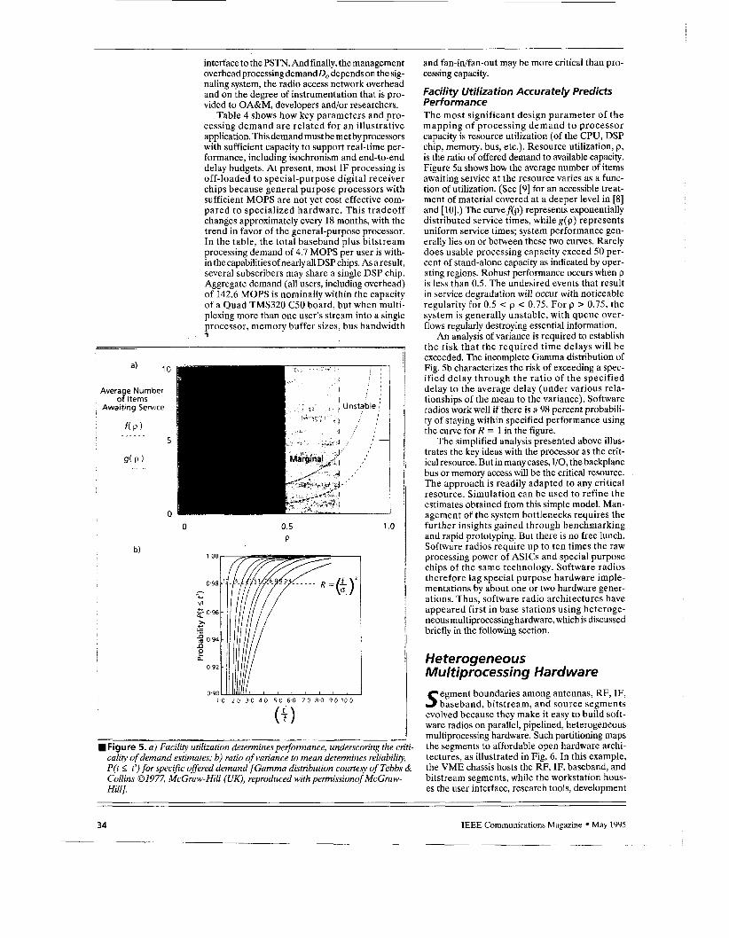
Figure 5. a ) Facility utilization determines perjormance, underscoring the criti- cality of demand estimates; b) ratio of variance to mean determines reliability, P(t 5 t’) for specific offered demand [Gamma distribution courteq of Tebbs & Collins 01977, McGraw-Hill (UK), reproduced with permissionof McGraw- Hill].
and fan-in/fan-out may be more critical than pro- cessing capacity.
Facility Utilization Accurately Predicts Performance The most significant design parameter of the mapping of processing demand to processor capacity is resource utilization (of the CPU, DSP chip, memory, bus, etc.). Resource utilization, p, is the ratio of offered demand to available capacity. Figure 5a shows how the average number of items awaiting service at the resource varies as a func- tion of utilization. (See [9] for an accessible treat- ment of material covered at a deeper level in [8] and [lo].) The curve f (p ) represents exponentially distributed service times, while g(p) represents uniform service times; system performance gen- erally lies on or between these two curves. Rarely does usable processing capacity exceed 50 per- cent of stand-alone capacity as indicated by oper- ating regions. Robust performance occurs when p is less than 0.5. The undesired events that result in service degradation will occur with noticeable regularity for 0.5 < p < 0.75. For p > 0.75, the system is generally unstable, with queue over- flows regularly destroying essential information.
An analysis of variance is required to establish the risk that the required time delays will be exceeded. The incomplete Gamma distribution of Fig. 5b characterizes the risk of exceeding a spec- ified delay through the ratio of the specified delay to the average delay (under various rela- tionships of the mean to the variance). Software radios work well if there is a 98 percent probabili- ty of staying within specified performance using the curve for R = 1 in the figure.
The simplified analysis presented above illus- trates the key ideas with the processor as the crit- ical resource. But in many cases, I/O, the backplane bus or memory access will be the critical resource. The approach is readily adapted to any critical resource. Simulation can be used to refine the estimates obtained from this simple model. Man- agement of the system bottlenecks requires the further insights gained through benchmarking and rapid prototyping. But there is no free lunch. Software radios require up to ten times the raw processing power of ASICs and special purpose chips of the same technology. Software radios therefore lag special purpose hardware imple- mentations by about one or two hardware gener- ations. Thus, software radio architectures have appeared first in base stations using heteroge- neous multiprocessing hardware, which is discussed briefly in the following section.
Heterogeneous Multiprocessing Hard ware
egment boundaries among antennas, RF, IF, S baseband, bitstream, and source segments evolved because they make it easy to build soft- ware radios on parallel, pipelined, heterogeneous multiprocessing hardware. Such partitioning maps the segments to affordable open hardware archi- tectures, as illustrated in Fig. 6. In this example, the VME chassis hosts the RF, IF, baseband, and bitstream segments, while the workstation hous- es the user interface, research tools, development
34 IEEE Communications Magazine May 1995
____ -_ ~-

I I ~ TI , OC-3, ATM, etc. to PSTN Multicoupler (Future) mezzanine bus
- i R F
&
D I A
b
a r d
0
R w e B
A t e
V D e r
b
b a
a d r d
C
0
0 r
- - -
Q U A D
D 5 P
b
a 0
2
i M e m
r Y
b
a r d
0
0
RF segment IF segment
Q A A D D
D D s s P P
b b
a ~ a
! U
0 0
: I r - - I
Baseband segment
-
9 A D
D 5 P
b
a r d
0
t a
m U X
-
V M E
h 0 S t
b
a r d
0
I I
w r k
t a t :
0
S
I 0 n
h 0 S t
- t I
-
L 0 C a I
D S P
-
-
G B
m e m
r Y
0
-
-
L 0 C a I
b U S
-
Bitstream Source segment 1 1 R?g2h 1 coding
Audio
-L Video
t-----)a I
-U
Facsimile
S
Graphics - 1
Workstation
Figure 6. Open component architecture supplies processing capaciy with affordable technology insertion.
tools and local source codingidecoding (Table 5 ) . In the most cost effective leveraging of open
architectures, VMEsystems are configured byexpe- rienced developers as heterogeneous multipro- cessors. The VME host serves as systems control processor. The DSP processors support the real- time channel processing stream, sometimes con- figured as one DSP per subscriber channel. The path from A/D to the first filtering/decimation stage typically uses a dedicated point-to-point mezza- nine interconnect such as DTConnect'" (DataTrans- lation). Timing the data transfersacross this buswith the point operations of the first filtering and deci- mation stage introduces inefficiencies that reduce throughput. Fan-out from IF processing to multiple baseband processing DSPs is also typically accom- plished via a dedicated point-to-point mezzanine path. Current implementations use customized fiber channel, TMS320/C50 or transputer links. As suggested in the figure, however, an open architecture optical mezzanine bus or local ATM switch should supplant today'svendor-unique point- to-point interconnects. An open architecture mezzanine bus with a capacity of 125 MHz x 16 bits per channel with an aggregate capacity of eight simultaneous channels would fill a critical void in contemporary open architecture standards.
Instead of configuring such heterogeneous multiprocessors at the board level, one might chose a preconfigured system. Mercury'", for example, offers a mix of SHARC 21060 (Analog Devices), PowerPC RISC, and Intel i860 chips
I301 cell site I I
W Table 4. Illustrative processing demand: analog mohilc ccllular base station.
with a unique Raceway interconnect with nominally three paths at 160 MB/sec interconnect capacity. Arrays of WE32s were used in ATglT's DSP-3 system. Arrays of i860s are available from Sky, CSPI, and others. Of particular note is the milita- rized TOUCHSTONE system which is also based on the 860. Such turnkey systems integrate block programming languages, automatic translation to C
IEEE Communications Magazine May 1905 35

iA,D/A) a i D
IF 1 Disital R X 130 72 MHz filters , Harris, Gray, E-Systems I
1 to 70 Msa sec Z i D e v t e s P m t e k DT
BS, SC Hosts
I ( B B = Baseband BS = Bitstream SC = Source Coding
.Table 5. Mapping of segments to open arclirtecture VME modules. -_
M580 x 0 ' Motorola, Force Intel
and machine code and extensive debugging support but at relatively high cost of entry. Vendor-unique turnkey systemsmaybe excellent choiceswhen there is agood match between the application and theven- dor's standard configured system. Vendor-unique details tend to limit hardware and software choic- es to the original vendor.
Architecture Trade0 f fs Software radios ideally place all IF, baseband, bit- stream and source processing in a single proces- sor. The assessment of the feasibility of the
I
I Time criticality
Hard real time I (ns-ps)
Buffered real time bs-ms)
Soft real time (ms - 100s ms)
Near real time (100s ms - sec)
On-line (sec-min)
Off-line (hrs-days-weeks)
Back end
Functionah t y
RF generation
Wideband filters
Spectrum characterization
Beam forming
Spreading/despreading
Equalization
Demodulation
Phase tracking
Narrowband filter
interference suppression
Framing
Forward error control
Interleaving
Signaling and control
Source coding
Power management
BEWSNR curve generation
Protocol interactions
Interference characterization
Network architecture
Hardware synthesis
software radio centers on comparing estimated demand to the capacities of the available processors. Implementations back off from the ideal single- CPU implementation where driven to do so by processor, memory, or interconnect technology limitations, or to achieve cost advantages (e.g., of off-loading filtering to aHarris chip so that the DSP is less expensive). Software tasks are then structured into managed objects designed to run on any DSP or CPU with access to the data and sufficient pro- cessing capacity.
Open Architecture Software Tools Remain Problematic
igure 7 shows how the time criticality of perfor- F mance varies considerably with functionality. No signal processing environments in existence fully span the range from hard real-time IF pro- cessing through off-line support. Each tool and environment on the market excels in one or more aspects of the required support, although a few integrated environments approach this ideal. UNIX works well as both VME host and work- station host in laboratory systems. Portable VME systems often use a DOSiWindows laptop for user interface and display in lieu of a workstation, with a DOSEISA or UNIX/VME signal processing configuration. SPOX and Harris Corporation's
Front end
C -
+ * * *
+ + + - *
+ * -
+ + *
+ * * *
t
A + + *
+ + + *
+ *
+ + -
+ 1
- + - - + +
Illustrative toot sets
Microcode 7 Hard real-time assembler 7 I .. 'I
Matbb
i Real time C-code
SPOX 1 Mercury
'"A?
TMS320 library Honeyw$
VHDL
Back end Low Moderate High cost cost cost
_I__ _- --__1________ -- _ _ ~
Figure 7. Sofhyare tools span the fuiictioii ypace, hut tool ~ntcgratron is farfiom seamless
36 ~
IEEE Communications Magazine May 1995

1B i MILSATCOM
100 M
10 M
1M
or purchase 10 K
1 K
too
10
1
GPS
N a t O P " ! a t I o
f t Y
A
X
M I
t a r Y
I
7
- relco MCR
? 9
b
s n e
U
S S
- NOT traffic x mgt
G 0 V e r n m e n t a I
Tech nology migration
$Billions
B l O O M
A B I O M
$ Millions
X $ l o O K
B l O K
A '$700
x '$10 L F1-q In-building PCS
Vest pocket/ I
palmtop wireless j A 1 Smaller businesses X
Log 10 (number cif p
I I Figure 8. Economics of project size versus number of projects drive software radio technology migratiorl.
real-time UNIX excel in near-real-time support. Software tools for heterogeneous distributed pro- cessing are developing rapidly, but lack extended precision arithmetic and standardized applica- tion-to-application interfaces.
The Signal Processing Workbench (SPW) and COSSAP environments each span a wide range from analysis and design through VHDL code generation. These environments include block diagram languages that allow the designer to express processingin asignal flow representation. Blockdia- gram languages are useful for concept develop- ment. The compilers can also map these to a n intermediate language (typically C) which can be compiledanddownloaded to target DSPchips(with up to an order of magnitude of performance degra- dation compared to handcodedc). Real-time access to the DSP status and performance is relatively hard to come by, however. Mercury and UNISYS' Mil- itarized Touchstone environments provide counter examples, offering real-time operating systemswith integrated performance monitoring and debug- ging capabilities. Some operating systems require one to build specialized status reporting tasks to send data of interest to the workstation. This is not a big impediment on a small project, but on larger, more complex projects, the integrated environments have significant advantages in reduced development times.
Rehosting tools tend to be aligned byvendorwith
Vendor-X providing a tool that will download C code to Vendor-X's own DSP hardware. The Signal Processing Workbench (SPW), Alta Corp., is a notable counter-example, with a very complete set of rehosting tools including targeting for sev- eral popular DSP cores and translation to VHDL for rapid transition to product hardware. Code libraries of such tool sets will evolve to standards- based suites of managed objets as object resource broker technlogy becomes more widely imple- mented in DSP tools.
Economics igure 8 shows the rough order of magnitude F relationship between size of a project (or pur-
chase) and the number of such projects (or poten- tial purchases) in the marketplace. Software radios are now in the segment of the market dominated by the military, big business (e.g., the telephone and wireless service providers) and governments. The companion applications articles describe projects with costs o n the order of a few million dollars to more than ten million, for example. Over time, the software radio will continue to move down and to the right as the size, power and cost of general purpose DSP chips, AID and DIA con- verters and related interconnect and memory allow. In addition, object management software technol- ogy applied to software radios offers powerful
37 IEEE Communications Magazine May 1995

- Sojbvare embodiment of tradition- ally analog and digital hardware functions opens up new levels of service quality and channel access flexibilig.
tools for managing the increased complexity of emerging radio network standards within affordable acquisition and maintenance budgets. Within a few hardware generations, software radioswill be in the vest-pocket and palmtop, providing the seam- less communications services we aspire to.
Conclusions oftware embodiment of traditionally analog S and digital hardware functions opens up new
levels of service quality and channel access flexi- bility. In applications where access to multiple bands with multiple radio access modes is a necessity, the software radio can reduce hardware size, weight and power through fewer radio units. The need for such improvement appeared as chron- ic "interoperability" problems in military applica- tions over a decade ago. Software radios address military issues as discussed in the companion arti- cle in this issue on Speakeasy. the military soft- ware radio. Software radios are also useful in introducing new channel access modes into bands where established modes must be accommodated for a number of years. As PCS and satellite mobile applications proliferate, the commercial sector is encountering continuing pressure for the increased flexibility and seamlessness of software radios. The software radio is a powerful architecture frame- work that helps us deliver such advanced radio services in a way that leverages the economics of contemporary microelectronics and software technologies.
Re feren ces (11 Bensley et al., Introduction to Parallel Supercomputing, The MITRE
121 Pentek Corporation, (Laurel, MD: SPY, 1994). 131 The Common Object Resource Broker: Architecture and Specifica-
tion, OMG 91.12.1, (Maynard, MA: Digital Equipment Corp. et al., 1992).
[4] Kondo, Matsuo and Suzuki. "A Software-Defined Architecture Con- cept forTelecommunication InformationSystems." ICC'94, (NY: IEEE Press, 1994).
[51 Voruganti, "A Global Network Management Framework for the 90's." ICC 94, (NY: IEEE Press, 1994). p. 1094.
161 Celestino and Claude, "Building a Platform Support Environment for TMN Applications", ICC 94, (NY: IEEE Press, 1994) p.1847.
[7] Mitola "Software Radios: Survey, Critical Evaluation and Future Directions," Proceedings of the National Telesystems Conference, (NY: IEEE Press, May 1992).
181 Kant, Introduction to Computer System Performance Evaluation. (NY: McGraw Hill, 1992).
191 Collins and Tebbs. Real Time Systems, (UK: McGraw Hill, 1977). [ l o ] Kleinrock, Queueing Systems, vol. 11, (NY: Macmillan, 1982). [111 Mouly and Pautet, The GSM System for Mobile Communications,
[121 Ziemer and Petersen. Digital Communications and Spread Spec-
Corporation, Bedford. M 4 1988.
(France: Palaiseau. 1992).
trum Systems, (NY: Macmillan, 1985). p. 694.
Biography
JOE MITOLA is a consulting scientist at the MITRE Corporation, McLean. Virginia, a not-for-profit corporation that operates federally funded research and development centers for the U.S. Government. His research inter- ests include quantitative methods in systems engineering. radio tech- .nology, and information theory. He advises the U.S. Government on large-scale systems architectures, telecommunications, and informa- t ion processing technologies. Prior t o joining MITRE in 1993, he was chief scientist of Electronic Systems, E-Systems Melpar, culminating more than a decade of positions of increasing responsibility. Earlier in his career, he worked for the Harris Corporation, Advanced Decision Systesms, and ITT. He began his career at the U.S. Department of Defense in 1967 He received a B.S.E.E. from Northeastern University in 1972 and an M.S.E. from Johns Hopkins University in 1974. In addi- tion, he passed the Ph.D. qualifying examinations in Information Pro- cessing (Articificial Interlligence) and Systems Theory at the University of Maryland in 1985. His e-mail address is: [email protected].
38 IEEE Communications Magazine May 1995

![Trends in the development of communication networks ...cs752/papers/cognitive-007.pdfused Ontogen, a semi-automatic ontology editor [6],to analyze the conference proceedings of IEEE](https://static.fdocuments.net/doc/165x107/5f100ac87e708231d447281e/trends-in-the-development-of-communication-networks-cs752paperscognitive-007pdf.jpg)