The SKA Molonglo Prototype (SKAMP) Project Molonglo 40th Anniversary, November 2005.
33
The The SKA SKA Molonglo Molonglo Prototype Prototype (SKAMP) (SKAMP) Project Project Molonglo 40th Anniversary, Molonglo 40th Anniversary, November November 2005 2005
-
date post
19-Dec-2015 -
Category
Documents
-
view
221 -
download
0
Transcript of The SKA Molonglo Prototype (SKAMP) Project Molonglo 40th Anniversary, November 2005.

TheThe SKASKA MolongloMolonglo PrototypePrototype (SKAMP)(SKAMP) ProjectProject
Molonglo 40th Anniversary,Molonglo 40th Anniversary, NovemberNovember 20052005

SKA Molonglo Prototype ProjectSKA Molonglo Prototype Project (SKAMP) (SKAMP) A new low-frequency spectral line instrument. Funded by the ARC, the Science Foundation and the
Major National Research Facilities Program. Project Goal: complete signal pathway – 2:1 dual
polarisation line feed; room temperature electronics; wideband digital signal processing; FX correlator.
Features: wide field of view, imaging, polarisation, spectral line capability, RFI mitigation (adaptive noise cancellation).
Strategy: parallel 3-stage re-development of MOST Science & technology prototyping for the Square
Kilometre Array (SKA) – 1% collecting area, wide-field imaging.

What is the SKA?What is the SKA?
Next generation radio telescope – 100 times improvement in many parameters.
Global collaboration. Proposed Australian site
in Mileura, WA. Operational 2020. 6 Key science projects.

SKAMP TeamSKAMP Team
Anne Green Duncan Campbell-Wilson Adrian Blake Ludi de Souza Tim Adams Martin Leung Sergey Vinogradov Daniel Mitchell Elaine Sadler 3 site Technical Officers
Michael Kesteven Tony Sweetnam John Bunton Frank Briggs John Kot
Bevan Jones Martin Owen Peter Liversidge
University of Sydney CSIRO – ATNF & ICT
Argus Technologies

Current Parameters for MOSTCurrent Parameters for MOST
Single frequency - 843 MHz continuum 3 MHz bandwidth, RHC polarisation 43" spatial resolution 18,000 sq metres collecting area Tsys 55K Field of view: >5 square degrees Sensitivity (7 position switching): 0.8 mJy Sensitivity for full 12 hr: 0.3 mJy Dynamic range: ~200:1

SKAMP 1 (2004 – 2005)SKAMP 1 (2004 – 2005)
Continuum correlator: 96 station, 4.4 MHz bandwidth, 843 MHz central frequency – > 4000 independent baselines, data rate 1sec
Sensitivity 0.8 mJy (12 hrs for complete synthesis; 7-position switching to gain wide field of view)
Continuous uv-coverage – correlation of inter-arm & between-arm stations to give good image fidelity
Programmable logic chips - FPGAs
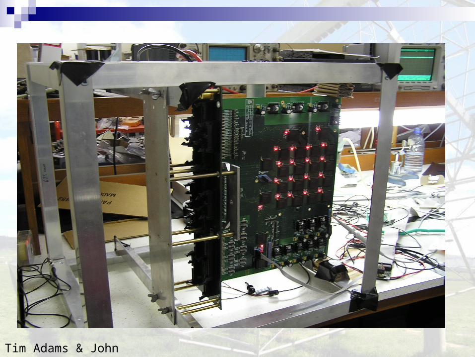
Tim Adams & John Bunton
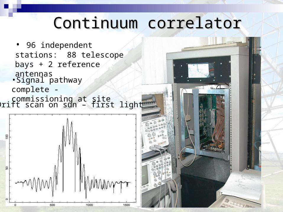
Continuum correlatorContinuum correlator
• Drift scan on sun – first light
• 96 independent stations: 88 telescope bays + 2 reference antennas
•Signal pathway complete - commissioning at site
SKAMP 2 (2005 – 2006)SKAMP 2 (2005 – 2006)
Spectral-line capability: 830 - 860 MHz with 2048 channels via FX correlator.
Existing front end retained – 96 stations; full correlation of all stations is highly redundant
Unchanged Tsys and angular resolution Optic fibre distribution network designed – trenching and
conduit completed Field of view roughly 4 square degrees Sensitivity for 12 hrs observation: 0.15 mJy Confusion limit of 0.12 mJy for 43" resolution Spectral line measurements not confusion limited

Wide-band uncooledWide-band uncooled Low Noise Amplifiers Low Noise Amplifiers
• ~20K noise temperature • Ambient temperature
operation• Possible extension to
operate 300-1400 MHz• Design simplified if
higher input impedance tolerated (50Ω input impedance design now)
• Mass production (8000 units) requires simple assembly design
Prototype 300-1000 MHz HEMT based LNA (Ralph Davison)
Gain
Noise Temperature
300 1000650Frequency (MHz)
0
10
20
50
30
40
Gai
n (d
B)
0
15
30
Noi
se T
empe
ratu
re (
K)

0
1
2
3
-6 -4 -2 0 2 4 6x (m)
y (m
)
x focus
Molonglo segmented parabola design Molonglo segmented parabola design gives good performance to ~2 GHzgives good performance to ~2 GHz
Flat mesh tied on supports at points shown
• Mesh supported at 0.6 m (2 ft) intervals in x direction.• Each section gives the same error for a linear fit to a
parabola.• 0.1 dB loss at 1420 MHz.• f/D = 0.25
Piecewise linear fit to parabola shape

Simulations to test surface approximationSimulations to test surface approximation
S. Vinogradov

SKAMP 3 (2006 – 2007)SKAMP 3 (2006 – 2007) Dual polarisation feed module – under range test. Next
stage to mount on Rapid Prototype Telescope (RPT). Baseline ripples to be measured.
First feed prototype 700 – 1100 MHz. Instantaneous bandwidth 100 MHz.
Once prototype approved, construct feeds for complete RPT.
Stage 1 RF beamformer – switched delay lines, design set by maximum frequency, ~3length, 100 phase step gives sufficient accuracy. Stage 2 beamforming also in feedline.
New mesh will reduce leakage to give Tsys of 40K. 12 hr sensitivity at 843 MHz ~0.1 mJy. Confused! Polarisation not confusion limited (assume 5% mean
source value).

Wideband feed prototype moduleWideband feed prototype module1. 8-element module, 1.4 m length
2. Wide-band dipoles – no moving parts
3. Polarisation axes oriented along & across axis of feed – better performance than dual-slant feeds
4. Range tested for 700 -1000 MHz
Leung

Beam & radiation patternsBeam & radiation patterns
-80 -60 -40 -20 0 20 40 60 80-30
-25
-20
-15
-10
-5
0Measured element patterns showing gain variation with scan angle (Transverse pol)
Scan angle (deg)
No
rma
lise
d E
-fie
ld (
dB
)
-80 -60 -40 -20 0 20 40 60 80-30
-25
-20
-15
-10
-5
0Measured element patterns showing gain variation with scan angle (Longitudinal pol)
Scan angle (deg)
No
rma
lise
d E
-fie
ld (
dB
)
1. Beam pattern – first sidelobe -12dB; cross polarisation -30dB at meridian, worst at high scan angle, up to -12dB
2. Scanning gain curve – flat to ±45°; cross polarisation -25dB or better
3. Transverse illumination pattern – HPBW 80°; cross polarisation worst at high scan angle, about -15dB
Figures show beam patterns and scanning gain variation for the two polarisations, transverse and longitudinal
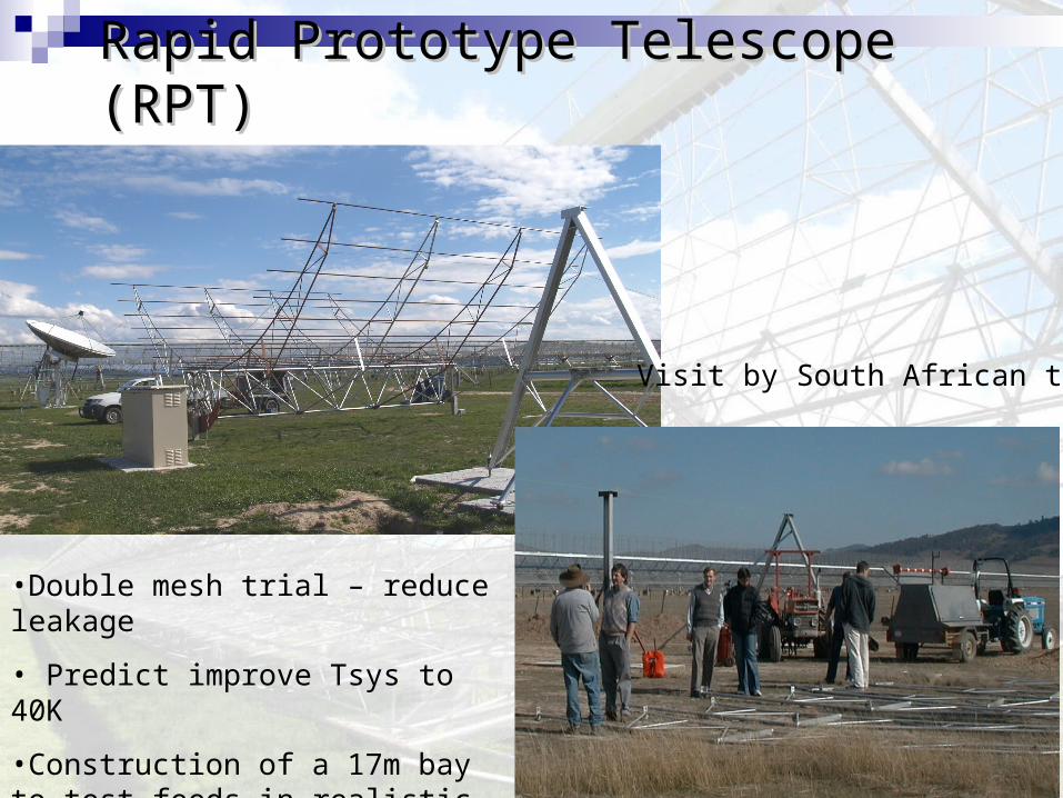
Rapid Prototype Telescope (RPT)Rapid Prototype Telescope (RPT)
Visit by South African team
•Double mesh trial – reduce leakage
• Predict improve Tsys to 40K
•Construction of a 17m bay to test feeds in realistic environment
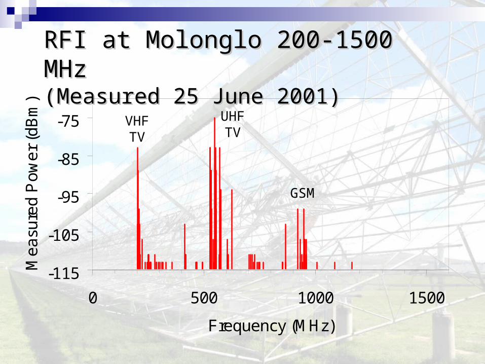
RFIRFI at Molonglo 200-1500 MHz at Molonglo 200-1500 MHz (Measured (Measured 225 June5 June 2001 2001))
-115
-105
-95
-85
-75
0 500 1000 1500
Frequency (MHz)
Me
asu
red
Po
we
r (d
Bm
)
GSM
VHFTV
UHFTV

RFI measurements in the fieldRFI measurements in the fieldat Dept of Defence HQ siteat Dept of Defence HQ site
Campbell-Wilson, Briggs, Mitchell
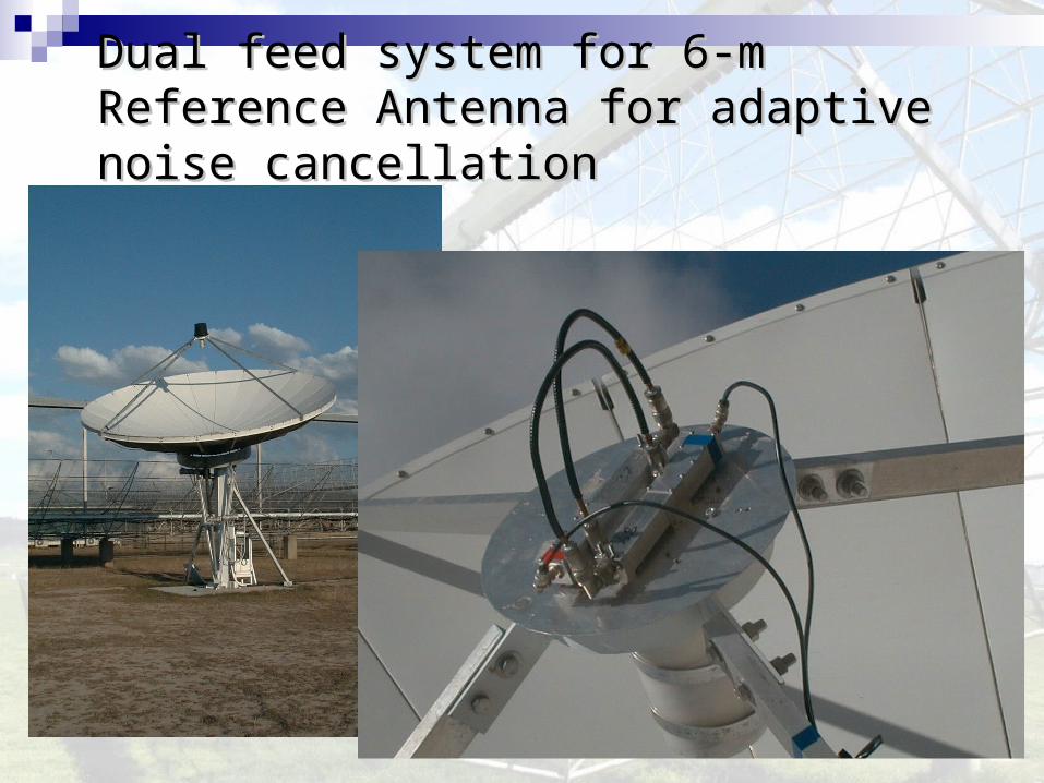
Dual feed system for 6-m Reference Dual feed system for 6-m Reference Antenna for adaptive noise cancellationAntenna for adaptive noise cancellation

A further extension: A further extension: uvuv-coverage with -coverage with additional stations on NS baselinesadditional stations on NS baselines????
•Good image fidelity in 6 hours
•Small reduction in sensitivity
•Double survey speed
•Model for 5 additional stations
(Bunton 2005)

Key science goalsKey science goals1. Blind survey of HI absorption in high redshift
galaxies – initially z~0.7, extend later. Test of mass-assembly of galaxies predictions from CDM scenario.
2. HI in emission – measure mass function directly. Redshift range z = 0.17 – 0.3. Challenging.
3. Cosmic magnetism studies – measure diffuse Galactic polarisation and a RM grid from many extragalactic sightlines.
4. High redshift galaxies found as USS sources.

Molonglo continuum confusion Molonglo continuum confusion (10 beams/source)(10 beams/source) at δ at δ= = 60°60°
0.01
0.1
1
10
0 500 1000 1500
Frequency (MHz)
Flu
x D
en
sity
(m
Jy)
Bock et al 1999SUMSS 843 MHz
Rengelink et al 1997WENSS 325 MHz
Wall 19941420 MHz
beam size:43” x 43” csc||
beam size:112” x 112” csc||
beam size:26” x 26” csc||

High image fidelity results from goodHigh image fidelity results from good uvuv-coverage -coverage

High-dynamic range continuum High-dynamic range continuum imaging imaging
StageI correlator will allow self-calibration strategies for MOST
Current MOST imaging dynamic range is 100-200:1 (similar to intrinsic dynamic range of VLA)
Self-calibration on VLA enables imaging dynamic ranges of more than 105:1
Current dynamic range of MOST limits imaging of faint sources, such as filaments of
supernova remnants, near bright sources like the Galactic Centre.
(MGPS Green et. al.)

1. Blind HI-absorption survey1. Blind HI-absorption survey
• New spectral line capability
• Measurements of HI absorption at z ~ 0.75 that capitalise on the large collecting area of MOST
• >10,000 sightlines to search for HI absorption – expect to detect ~50 sources in limitedredshift range in 2400 sq deg
• Few detections – eg Darling et al. (2004) of galaxy z=0.78 in front of z=1.992 quasar.
Stage 2: enables ΩHI measurements at z ~ 0.75,
where existing results are not well constrained
(Lane 2000)
(Lane and Briggs 2001)

When & how is HI assembled into When & how is HI assembled into galaxies? galaxies? (Baugh et al 2004)(Baugh et al 2004)
Data-free zone

2. High-redshift HI emission in2. High-redshift HI emission in galaxies galaxies
8
9
10
11
0 0.05 0.1 0.15 0.2 0.25 0.3
Redshift z
HIPASS (500s)
Molonglo (10x12 h)
(12 h)
log
10 M
lim (
HI)
(M
⊙)
Typical bright spiral
HI in the nearby Circinus galaxy (Jones et al. 1999)
The Molonglo telescope will reach HI mass limits typical of bright spiral galaxies at z=0.2 (lookback time ~3 Gyr), allowing a direct measurement of evolution in the HI mass function. Challenging project.

– cloud collapse / star formationcloud collapse / star formation– stellar activity / stellar outflowsstellar activity / stellar outflows – ISM turbulence / gas motionsISM turbulence / gas motions
– supernova remnantssupernova remnants
– stability of galactic disksstability of galactic disks– acceleration / propagation / acceleration / propagation /
confinement of cosmic raysconfinement of cosmic rays– heating in galaxy clustersheating in galaxy clusters
– AGNs / JetsAGNs / Jets
3. Cosmic Magnetism3. Cosmic Magnetism
Proplyd in Orion MHD turbulence
SN 1006 Merger in gal. cluster
Magnetism is one of the fundamental forces in Nature, Magnetism is one of the fundamental forces in Nature, but its role and origin is largely unknown !but its role and origin is largely unknown !
Magnetism is crucial for :Magnetism is crucial for :

Rotation Measure GridRotation Measure Grid
• Probes magnetic fields in galaxies, the Milky Way & clusters
• Rotation measure grid of background sources and polarisation of the diffuse Galactic field
300 RMs through the LMC (Gaensler et al 2004)

4. 4. High-redshift radio galaxies from High-redshift radio galaxies from spectral studies, if lower frequency spectral studies, if lower frequency range implemented range implemented
Radio spectral index measurements over the range 300 –1400 MHz are an efficient way of selecting high-redshift (z>3) radio galaxies (e.g. de Breuck et al. 2000, 2004).
Radio galaxy TN0924-2201 at
z=5.19 (van Breugel et al. 1999)

Summary of SKAMP Project statusSummary of SKAMP Project status
96-station continuum correlator being commissioned – first light. (SKAMP 1)
Optic fibre network conduit laid, fibre on order; spectral-line correlator designed and being built, calibration & image processing software being planned. (SKAMP 2)
8-element module of prototype feed under test; RPT nearing mechanical completion; RF beamformers in design. (SKAMP 3)
Simulated performance - sensitivity 0.12 mJy for 12 hour observation – for 43” resolution, data are confusion limited for continuum images but not for spectroscopy or polarimetry

A new lease on life for a mature instrument

First Fringes – single baseline & First Fringes – single baseline & interim correlator interim correlator
Team:GreenCampbell-WilsonKestevenBuntonAdams*LeungBlake*ChippendaleVinogradov*MitchellBriggsSweetnamSadler