Cost Effectively Increasing the Electrical Output of Solar Panels

International Conference on Renewable Energies and Power Quality (ICREPQ’17) Malaga (Spain), 4th to 6th April, 2017
Renewable Energy and Power Quality Journal (RE&PQJ) ISSN 2172-038 X, No.15 April 2017
The Simulation Analysis for Increasing Output Power in Photovoltaic System by Using Segmented String and Constant Voltage Boost Chopper with MPPT
Xiaoyang Li, Teruhisa Kumano
Electrical engineering program at graduate school of Science and Technology, Meiji University. Campus of Ikuda 1-1-1 Higashi-Mita Tama-ku Kawasaki-shi Kanagawa, 214-8571(Japan)
Phone: +81449347294 e-mail:[email protected], [email protected]
Abstract. In photovoltaic (PV) generation system, PV panels can be easily covered by shadows from obstacles around the power station. These shadows cannot cover all of the panels so it called partial shades. In this situation PV system loses its power output very large. This paper gives a software plus hardware’s proposal to increase power output of PV system which is covered by partial shades. In this proposal, new array circuit and new chopper are developed and compared with former types in power output level and quality. We conclude newer chopper’s power output can decrease the partial shades’ loss from the former types’ 40% to the newer types’ 9%.
Key words
PV Generation System, Partial Shades, Constant Voltage Boost Chopper, Segmented String, MPPT Algorithm.
1. Introduction
Nowadays, PV panels are usually connected as first in series and then in parallel to make an array [1] in a rooftop PV generation system. Further, this array connects to open looped boost or buck chopper, changes voltage and uses maximum power point tracking algorithm (MPPT) to find the maximum power point (MPP). This conventional system has advantages as following: 1. Simple. 2. Cheap. However it has defects as following: 1. Partial shades influences array’s power output. 2. Because the chopper is open looped, MPPT algorithm
effects its voltage raising rate. 3. Since we do not have any information from array,
array’s error cannot be diagnosed and partial shades’ influences cannot be measured and calculated.
Since solar battery cell’s I-V and P-V characteristics are nonlinear, for getting the maximum output power, chopper must be calculating, searching, and holding on the MPP at all time. It is the MPPT technology and now we have had several well-known methods such as Perturb and Observe Method (P&O) [2], Incremental Conductance Method (INC) [3], Scan Method (Scan) [4], Constant Voltage Method (CV) [5] and so on. Although in these methods, P&O and INC have the most stable performance and the highest effectiveness, in engineering applications lots of points can be still improved. For example, classical P&O and INC include
processes like data collection, calculation, comparison, and action [2], [3]. To improve the performance of these method, one of the ways is the usage of the Fuzzy algorithm. It can be applied in calculation [6], comparison [7] and action [8], [9] processes. But these improvement points are all built only on software, decreasing the influences of partial shades are still insufficient. In reality, obstacle free site is very rare for building a rooftop PV generation system. Usually, some obstacles (like trees or houses) are around the site. Every day, these obstacles’ shadows cover parts of array cyclically and make the output of the PV system unstable. In this paper, the improvement points of existing system are built on not only software but also on hardware. Furthermore, a system will be proposed which can decrease the loss of partial shades’ influences. In the hardware side: 1. To change the open looped chopper to the close
looped chopper; 2. To change the connection of panels; 3. To add MPPT algorithm in close looped chopper. In the software side, it changes the comparing point in classical P&O and INC from key points of axis (like zero point or 1/2 point) to better and wiser points. As the result, comparing the existing system, proposed system can decrease the output power loss due to partial shades successfully from about 40% to 9%.
2. Objectives
This study develops a system that can increase the power output of PV array covered by partial shades. This system has these features as following. 1. To develop a kind of constant voltage boost chopper
to hold on voltage which can turn on blocking diodes even in partial shades.
2. To bridge short wires between strings and to make strings shorter. Then set ammeters on the short wires to get data from bridge current.
In this paper we verify that this system can work theoretically as expected by numerical simulation.
https://doi.org/10.24084/repqj15.399 575 RE&PQJ, Vol.1, No.15, April 2017

Table I. The spec of the proposed system Power P=5KW Number of panels 24 pieces Output voltage of array Vp=275VDC @MPP Output current of array Ip=21ADC @MPP Output voltage of chopper Vo=400VDC @MPP Output current of chopper Io=12.5A @MPP Switch frequency f=20kHz Allowable ripple voltage VrP-P=5V (MAX)
3. Proposed Systems And Simulation Setting
Table I shows the spec of the proposed system.
A. Design Of Closed Looped Constant Voltage Boost Chopper (CVBC) with MPPT Algorithm
Figure 1 shows open looped chopper circuit. Equation (1) is its transfer function base on duty rate D and it looks like a second order delay system.
G s (1)
Because duty rate D can control this system, controller block diagram can be designed easily as Fig.2.
From Fig.2, controller circuit can be designed easily as Fig.3. In the center of Fig.3, there is a single pole regulator and on the left is PWM wave generator. VB is feedback input which is from the chopper output Vo. VC is reference voltage source and if MPPT algorithm replaces VC this controller becomes a CVBC with MPPT like Fig.4. In Fig.4, down center’s square block called C Block [10], with this block, C can be used to program P&O, INC or other MPPT algorithms. Numerical simulation uses Powersim’s PSIM package to draw the system’s schematics, simulate the change of irradiation and partial shades’ influences and verify the performance of the proposed system.
B. The Segmented Strings And Bridge Current’s Analysis
The advantage of segmented strings is decreasing the influences of partial shades. Figure 5 shows a partial shade (black part) on normal string (first in series and then in parallel). Because this string loses voltage, it cannot output any energy.
Fig.1 Open looped chopper circuit
Fig.2 Controller block diagram
Fig.3 CVBC’s controller
Fig.4 CVBC with MPPT
Fig.5 Partial shades’ influences on normal string
(Part of black is shadow and the same below)
https://doi.org/10.24084/repqj15.399 576 RE&PQJ, Vol.1, No.15, April 2017
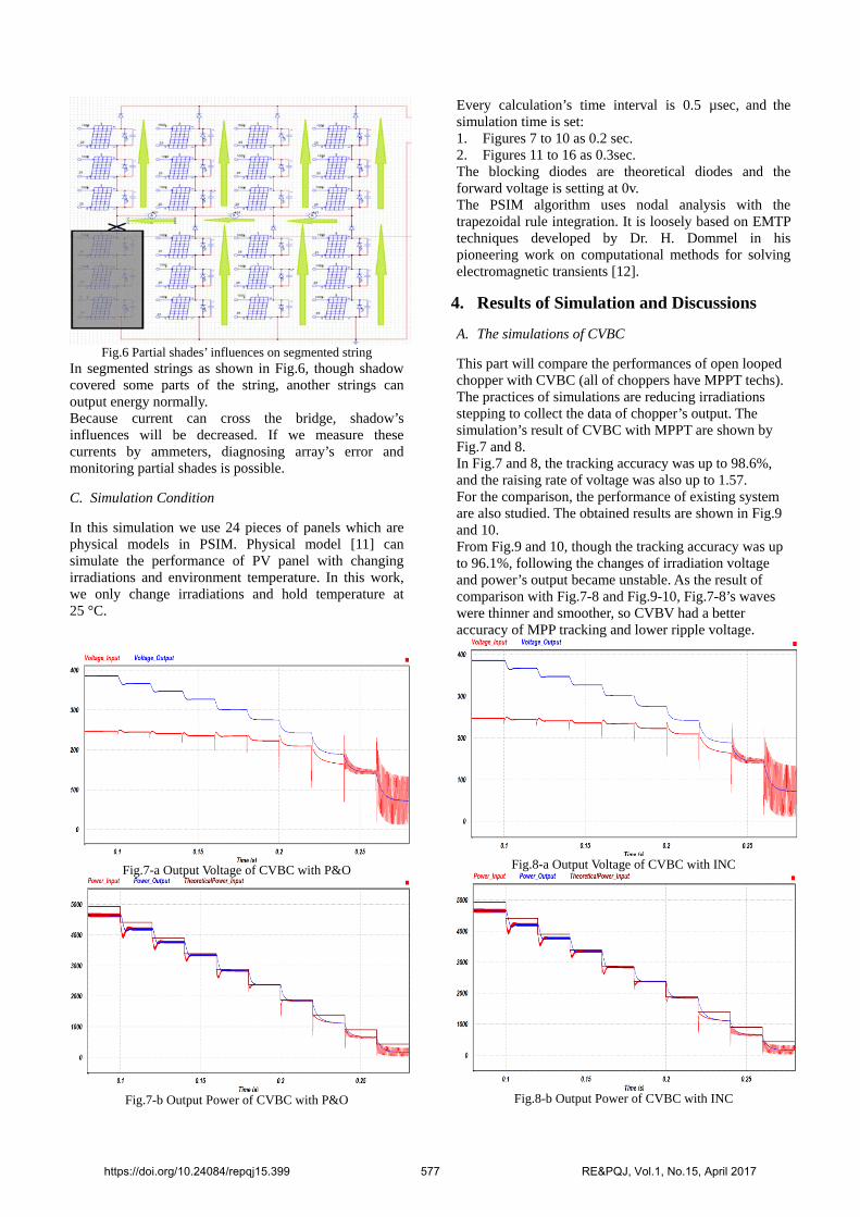
Fig.6 Partial shades’ influences on segmented string
In segmented strings as shown in Fig.6, though shadow covered some parts of the string, another strings can output energy normally. Because current can cross the bridge, shadow’s influences will be decreased. If we measure these currents by ammeters, diagnosing array’s error and monitoring partial shades is possible.
C. Simulation Condition
In this simulation we use 24 pieces of panels which are physical models in PSIM. Physical model [11] can simulate the performance of PV panel with changing irradiations and environment temperature. In this work, we only change irradiations and hold temperature at 25 °C.
Every calculation’s time interval is 0.5 µsec, and the simulation time is set: 1. Figures 7 to 10 as 0.2 sec. 2. Figures 11 to 16 as 0.3sec. The blocking diodes are theoretical diodes and the forward voltage is setting at 0v. The PSIM algorithm uses nodal analysis with the trapezoidal rule integration. It is loosely based on EMTP techniques developed by Dr. H. Dommel in his pioneering work on computational methods for solving electromagnetic transients [12].
4. Results of Simulation and Discussions
A. The simulations of CVBC
This part will compare the performances of open looped chopper with CVBC (all of choppers have MPPT techs). The practices of simulations are reducing irradiations stepping to collect the data of chopper’s output. The simulation’s result of CVBC with MPPT are shown by Fig.7 and 8. In Fig.7 and 8, the tracking accuracy was up to 98.6%, and the raising rate of voltage was also up to 1.57. For the comparison, the performance of existing system are also studied. The obtained results are shown in Fig.9 and 10. From Fig.9 and 10, though the tracking accuracy was up to 96.1%, following the changes of irradiation voltage and power’s output became unstable. As the result of comparison with Fig.7-8 and Fig.9-10, Fig.7-8’s waves were thinner and smoother, so CVBV had a better accuracy of MPP tracking and lower ripple voltage.
Fig.7-a Output Voltage of CVBC with P&O
Fig.7-b Output Power of CVBC with P&O
Fig.8-a Output Voltage of CVBC with INC
Fig.8-b Output Power of CVBC with INC
https://doi.org/10.24084/repqj15.399 577 RE&PQJ, Vol.1, No.15, April 2017

Fig.9-a Output Voltage of open looped chopper with P&O
Fig.9-b Output Power of open looped chopper with P&O
Fig.10-a Output Voltage of open looped chopper with INC
Fig.10-b Output Power of open looped chopper with INC
B. The characteristics of segmented string
The advantage of segmented strings is that it can reduce the influences of partial shades’ covering. This part will show the performances of CVBC with MPPT + segmented strings covered by partial shades. As the comparison CVBC with MPPT and open looped chopper with MPPT+ normal strings will be also shown at this part. In this paper, partial shades appear at one of the eight places (like Fig.6) in the array randomly and change its position every 0.02sec.The normal strings is shown by Fig.5. From Fig.11 and 12, raising rate of voltage is 1.53 and the partial shades’ loss of power output is about 9%.
Then looks at the performances of CVBC with MPPT + normal strings. As Fig.13 and 14, the raising rates of voltage increased little to about 1.57. The loss of output power had been up a little from 9% to 14%. Figure 15 and 16 show what about the performances of open looped chopper with MPPT + normal strings in influences of partial shades are. From Fig.15-16, raising rates of voltage were very unstable (1.90 and1.19) and the loss of output power had been up from 9% to about 20%-40%. It is hard to use. Summarizing all these results, we might conclude that the proposed system has better stable performance in which the ripple voltage magnitude and the output power loss by partial shades are lower.
Fig.11-a Output Voltage of CVBC with P&O + segmented
strings in influences of partial shades
Fig.11-b Output Power of CVBC with P&O + segmented
strings in influences of partial shades
https://doi.org/10.24084/repqj15.399 578 RE&PQJ, Vol.1, No.15, April 2017
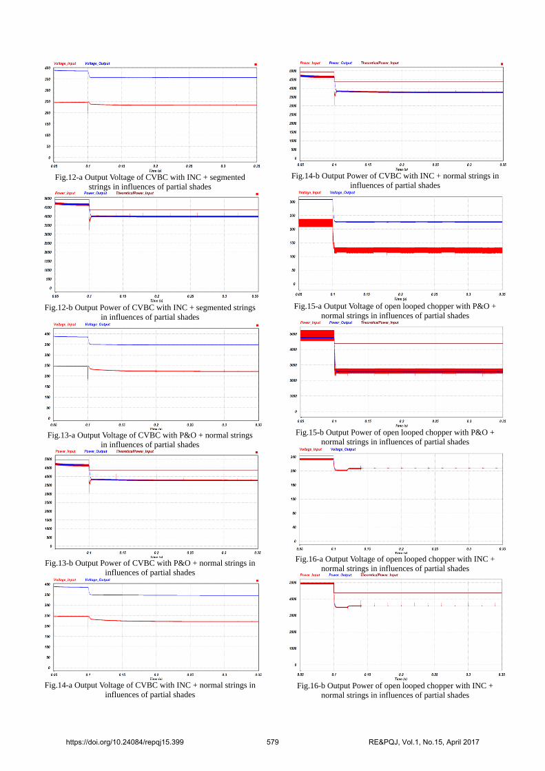
Fig.12-a Output Voltage of CVBC with INC + segmented
strings in influences of partial shades
Fig.12-b Output Power of CVBC with INC + segmented strings
in influences of partial shades
Fig.13-a Output Voltage of CVBC with P&O + normal strings
in influences of partial shades
Fig.13-b Output Power of CVBC with P&O + normal strings in
influences of partial shades
Fig.14-a Output Voltage of CVBC with INC + normal strings in
influences of partial shades
Fig.14-b Output Power of CVBC with INC + normal strings in
influences of partial shades
Fig.15-a Output Voltage of open looped chopper with P&O +
normal strings in influences of partial shades
Fig.15-b Output Power of open looped chopper with P&O +
normal strings in influences of partial shades
Fig.16-a Output Voltage of open looped chopper with INC +
normal strings in influences of partial shades
Fig.16-b Output Power of open looped chopper with INC +
normal strings in influences of partial shades
https://doi.org/10.24084/repqj15.399 579 RE&PQJ, Vol.1, No.15, April 2017

5. Conclusions
This paper proposed a new PV system, in which the following special features exist: 1. To add feedback circuit to existing open looped
chopper in PV system and make it become a CVBC. 2. To change the first in series and then in parallel array
circuit (normal strings) to segmented strings. 3. To get better control accuracy, use INC in CVBC. As the result of simulation analysis, the proposed system can work in effect. Table II shows the comparison of the numerical results in all simulations. The conclusions are: 1. Segmented strings and CVBC with MPPT can
decrease the partial shades’ loss of output power in PV generation system. As simulations’ result, CVBC with INC + segmented strings had reduced this loss successfully from 40% to 9%.
2. Compared with open looped chopper, closed looped chopper can hold array’s output voltage and make chopper’s voltage raising rate better. Because the stable raising rate, system’s total power loss could be lower.
3. The proposed system can hold the output voltage at a high level. It will reduce the need of inverter’s redundant capacity, decrease system’s failure rate and at the same time increase inverter’s lifetime.
In near future, the authors are going to realize the proposed system and verify the validity by experimental basis. In this experiment the bridge current data will be used for identifying the area of partial shades and predicting the output power’s loss.
6. References
[1]JPEA, Photovoltaic Power Generating System 5th edition (In Japanese), OHMsha (2015), pp.30 [2]N.Femia et al., “Optimization of perturb and observe maximum power point tracking method”, in IEEE Transactions on Power Electronics 2005, Vol.20, pp. 963-973. [3]M. Lokanadham, K. Vijaya Bhaskar, “Incremental Conductance Based Maximum Power Point Tracking (MPPT) for Photovoltaic System” in IJERA2012, Vol.2, pp. 1420-1424. [4]Kazutaka Itako, Introduction to Photovoltaic Power Conditioning system (In Japanese), OHMsha (2014), pp.31-33. [5]R.Faranda and S.Leva, Energy comparison of MPPT techniques for PV systems, WSEAS TRANSACTIONS on POWER SYSTEMS, Issue 6, Vol.3, pp.446-455. [6]M.Sheraz and M.A.Abido, An Efficient Logic Based Maximum Point Tracking Controller for Photovoltaic Systems, RE&PQJ, Vol.1, No.11, pp.146-151. [7]Mohamed A.El-sayed and Steven Leeb, Fuzzy Logic Based Maximum Power Point Tracking Using Boost Converter for Solar Photovoltaic System in Kuwait, RE&PQJ, Vol,1, No.13, pp.13-18. [8]J.Aymen et al. , Comparison of Fuzzy and Neuro-Fuzzy Controllers for Maximum Power Point Tracking of Photovoltaic Modules, RE&PQJ, Vol.1, No.14, pp.796-800. [9]A.Al Nabulsi and R.Dhaouadi, Fuzzy Logic Controller Based Perturb and Observe Maximum Power Point Tracking, RE&PQJ, Vol.1, No.10, pp.1150-1155. [10]PSIM User Guide Version 10.0 (In Japanese), Powersim (2011), pp. 213-214 [11]PSIM User Guide Version 10.0 (In Japanese), Powersim (2011), pp.142-144 [12]What numerical algorithm does PSIM use? Retrieved Jan. 16th, 2017, from PSIM’s homepage: https://powersimtech.com/support/resources/faq/q-numerical-algorithm-psim-use/
Table II: The Results of Numerical Simulation
The Existing Systems The Proposed Systems
Open Looped Chopper with
P&O + Normal Panel String
Open Looped Chopper with INC + Normal Panel String
CVBC with P&O + Normal
Panel String
CVBC with INC+ Normal Panel String
CVBC with P&O +
Segmented String
CVBC with INC +
Segmented String
Partial Shades’ Loss
41.72% (0%)
18.09% (-23.63%)
14.2% (-27.52%)
14.1% (-27.53%)
9.16% (-32.56%)
9.00% (-32.72%)
Output Voltage 225.86 VDC 213.52 VDC 346.80VDC 347.08VDC 357.6 VDC 357.1VDC
Raising Rate of Output Voltage
1.90 1.19 1.57 1.58 1.53 1.53
Ripple Voltage (Peak to Peak)
2.53V 2.20 V 1.60V 1.65V 1.58 V 1.59 V
https://doi.org/10.24084/repqj15.399 580 RE&PQJ, Vol.1, No.15, April 2017