The Shared Apex Loop Array - American Radio Relay … Shared Apex Loop Array This compact...
5
44 October 2012 ARRL, the national association for Amateur Radio ® www.arrl.org from loop 1 with delayed signals from loop 2. Using this principle, a time delay difference is selected so that signals arriving from a direction that is opposite the favored direction, when combined, are maximally attenuated. If the array is configured in this manner, signals arriving from the favored direction are attenuated less than signals coming from other directions. This directional effect is largely frequency independent up to a maximum frequency. The array also ben- efits from its employ- ment of electrically small loop elements that exhibit a pro- foundly bidirectional characteristic, with lobes off of their ends and sharp nulls to their broadside. The combination of the small loop element and true time delay operation join together to provide the horizontal response as modeled with 4NEC2 and shown in Figure 3. This pattern shape is largely preserved over the frequency range, but the forward gain decreases significantly as the operating fre- quency is lowered. Combiner Amplifier The combiner amplifier shown in Figure 2 is a three terminal device that must provide proper termination for the delay and reference lines, port-to-port timing and amplitude accu- racy as well as amplification. It is essential to understand the port characteristics of the combiner amplifier before we consider its internal circuitry. The Shared Apex Loop Array This compact directional wideband receiving antenna can reduce interference. common vertical plane, and held in tension by an anchor forming a horizontal base that is spaced a few inches above the ground. Each loop is constructed as an endless wire loop that is routed through a group of ferrite cores forming a current transformer acting as a coupling link. The coupling link is posi- tioned at a distance from the mast and is connected so that the anchor side of the transformer is connected to the center coax conductor of a loop feed line. The loop feed line from loop 1 is connected to a reference line. The opposite end of the reference line connects to an input port of a combiner amplifier that will be described later in this article. The loop 2 coupling link is positioned at a distance from the mast and is connected so that the anchor side of the transformer is connected to the center coax conductor of a loop feed line. The opposite end of the feed line is connected to a delay line. The opposite end of the delay line is connected to a second port of the combiner amplifier. The output signal from the array is delivered from the combiner amplifier to the receiver. The array operates using the true-time-delay principle of operation by combining signals I designed a compact directional receiving antenna that effectively reduces interference over a wide frequency range. Mark Bauman, KB7GF Effective receiving antennas are becoming an indispensible part of our amateur arsenal as we battle interference from both natural and man-made sources. Many of us do not have the acreage to erect directional antennas, especially on the lower bands, so we use shortened verticals and low hanging dipoles, which provide essentially omnidirectional response. As a result, our ears are bombarded with signals and interference from all direc- tions when our transmitting antenna doubles as our receiving antenna. Antenna Concept To assist in this battle, I designed a compact directional receiving antenna that effectively reduces interference over a wide frequency range. The array described here is compact, having a loop spacing of only 2 inches, a 10 foot tall mast, an array length of 20 feet and a base height of 6 inches. In this configuration, the array delivers directivity over a frequency range of 500 kHz to 22 MHz and exceptional sensitivity above 6 MHz. A ground mounted version of the shared apex loop array is shown in Figure 1 and schemati- cally in Figure 2. The antenna utilizes two closely spaced loops that are interconnected via a delay line to deliver healthy front to side and front to back ratios over a wide frequency range. A non-conductive mast guides the vertical side of two identical right-triangular- shaped wire loops to form a common or shared apex. Each loop is draped in a sym- metrical manner about the mast, oriented in a
Transcript of The Shared Apex Loop Array - American Radio Relay … Shared Apex Loop Array This compact...

44 October 2012 ARRL, the national association for Amateur Radio® www.arrl.org
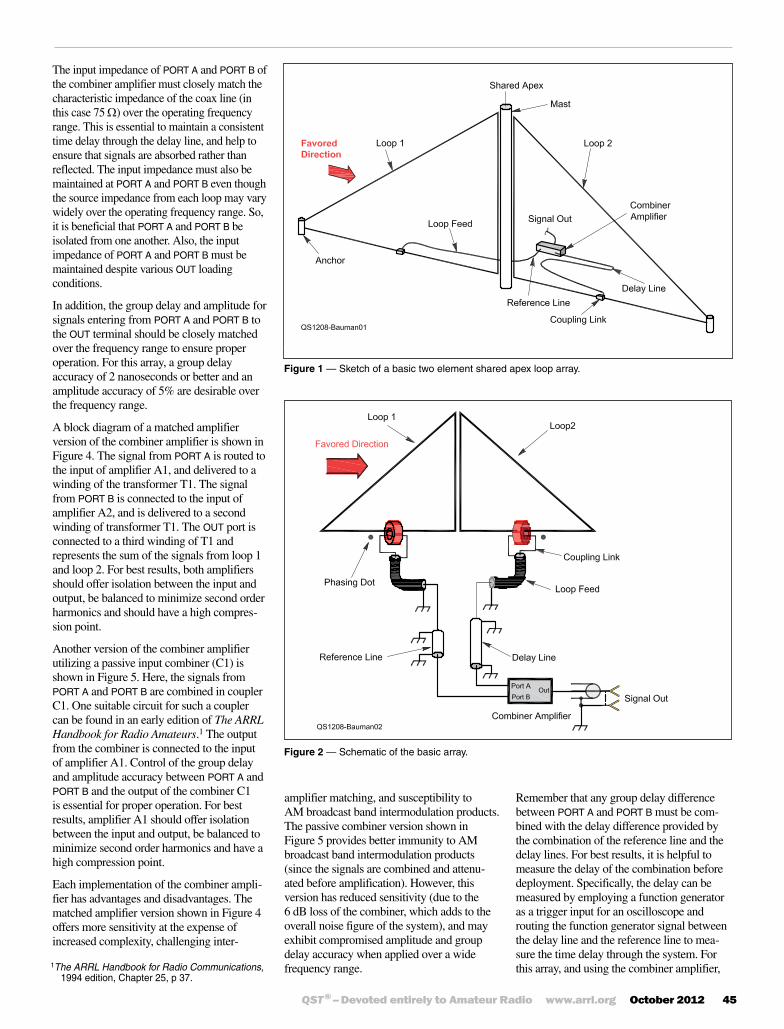
from loop 1 with delayed signals from loop 2. Using this principle, a time delay difference is selected so that signals arriving from a direction that is opposite the favored direction, when combined, are maximally attenuated. If the array is configured in this manner, signals arriving from the favored direction are attenuated less than signals coming from other directions. This directional effect is largely frequency independent up to a maximum frequency.
The array also ben-efits from its employ-ment of electrically small loop elements that exhibit a pro-foundly bidirectional
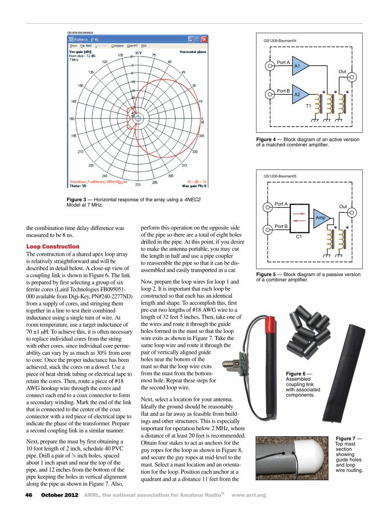
characteristic, with lobes off of their ends and sharp nulls to their broadside. The combination of the small loop element and true time delay operation join together to provide the horizontal response as modeled with 4NEC2 and shown in Figure 3. This pattern shape is largely preserved over the frequency range, but the forward gain decreases significantly as the operating fre-quency is lowered.
Combiner AmplifierThe combiner amplifier shown in Figure 2 is a three terminal device that must provide proper termination for the delay and reference lines, port-to-port timing and amplitude accu-racy as well as amplification. It is essential to understand the port characteristics of the combiner amplifier before we consider its internal circuitry.
The Shared Apex Loop ArrayThis compact directional wideband receiving antenna can reduce interference.
common vertical plane, and held in tension by an anchor forming a horizontal base that is spaced a few inches above the ground.
Each loop is constructed as an endless wire loop that is routed through a group of ferrite cores forming a current transformer acting as a coupling link. The coupling link is posi-tioned at a distance from the mast and is connected so that the anchor side of the transformer is connected to the center coax conductor of a loop feed line. The loop feed line from loop 1 is connected to a reference line. The opposite end of the reference line connects to an input port of a combiner amplifier that will be described later in this article.
The loop 2 coupling link is positioned at a distance from the mast and is connected so that the anchor side of the transformer is connected to the center coax conductor of a loop feed line. The opposite end of the feed line is connected to a delay line. The opposite end of the delay line is connected to a second port of the combiner amplifier. The output signal from the array is delivered from the combiner amplifier to the receiver.
The array operates using the true-time-delay principle of operation by combining signals
I designed a compact directional receiving antenna that
effectively reduces interference over a wide frequency range.
Mark Bauman, KB7GFEffective receiving antennas are becoming an indispensible part of our amateur arsenal as we battle interference from both natural and man-made sources. Many of us do not have the acreage to erect directional antennas, especially on the lower bands, so we use shortened verticals and low hanging dipoles, which provide essentially omnidirectional response. As a result, our ears are bombarded with signals and interference from all direc-tions when our transmitting antenna doubles as our receiving antenna.
Antenna ConceptTo assist in this battle, I designed a compact directional receiving antenna that effectively reduces interference over a wide frequency range. The array described here is compact, having a loop spacing of only 2 inches, a 10 foot tall mast, an array length of 20 feet and a base height of 6 inches. In this configuration, the array delivers directivity over a frequency range of 500 kHz to 22 MHz and exceptional sensitivity above 6 MHz.
A ground mounted version of the shared apex loop array is shown in Figure 1 and schemati-cally in Figure 2. The antenna utilizes two closely spaced loops that are interconnected via a delay line to deliver healthy front to side and front to back ratios over a wide frequency range. A non-conductive mast guides the vertical side of two identical right-triangular-shaped wire loops to form a common or shared apex. Each loop is draped in a sym-metrical manner about the mast, oriented in a
QST® – Devoted entirely to Amateur Radio www.arrl.org October 2012 45
The input impedance of PORT A and PORT B of the combiner amplifier must closely match the characteristic impedance of the coax line (in this case 75 W) over the operating frequency range. This is essential to maintain a consistent time delay through the delay line, and help to ensure that signals are absorbed rather than reflected. The input impedance must also be maintained at PORT A and PORT B even though the source impedance from each loop may vary widely over the operating frequency range. So, it is beneficial that PORT A and PORT B be isolated from one another. Also, the input impedance of PORT A and PORT B must be maintained despite various OUT loading conditions.
In addition, the group delay and amplitude for signals entering from PORT A and PORT B to the OUT terminal should be closely matched over the frequency range to ensure proper operation. For this array, a group delay accuracy of 2 nanoseconds or better and an amplitude accuracy of 5% are desirable over the frequency range.
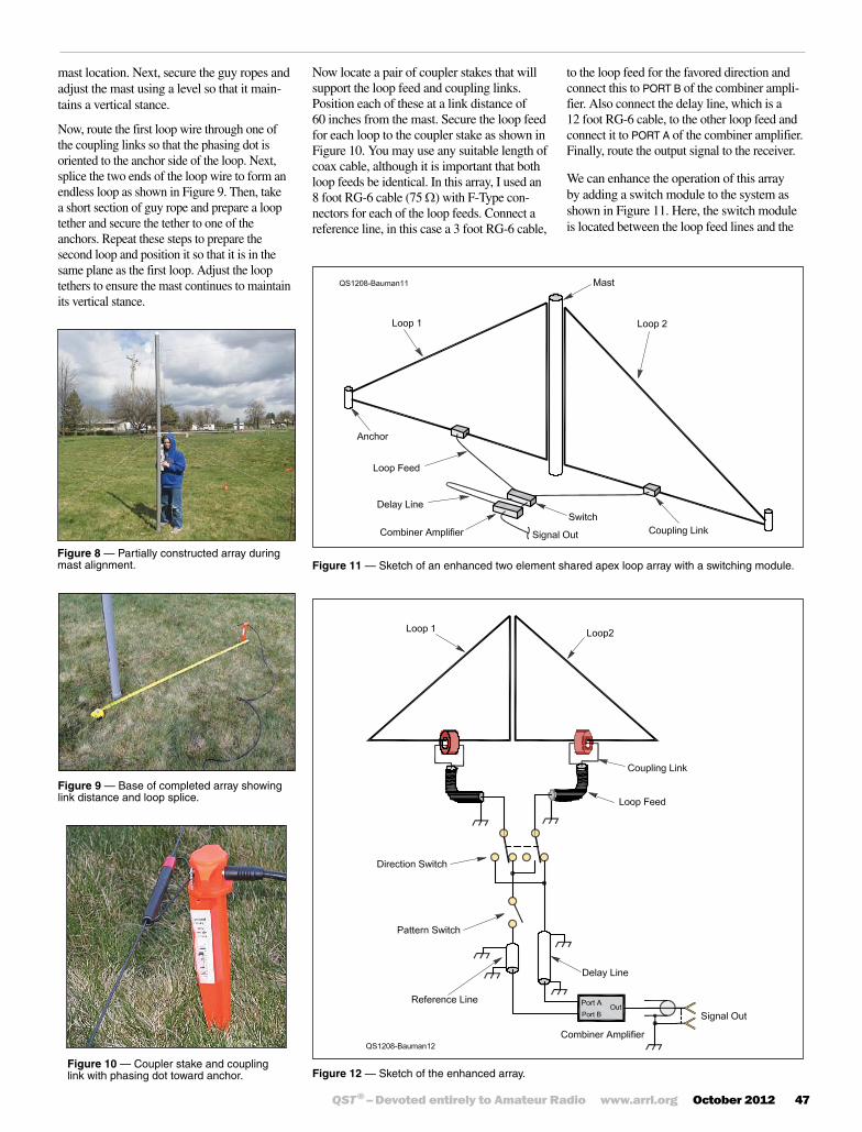
A block diagram of a matched amplifier version of the combiner amplifier is shown in Figure 4. The signal from PORT A is routed to the input of amplifier A1, and delivered to a winding of the transformer T1. The signal from PORT B is connected to the input of amplifier A2, and is delivered to a second winding of transformer T1. The OUT port is connected to a third winding of T1 and represents the sum of the signals from loop 1 and loop 2. For best results, both amplifiers should offer isolation between the input and output, be balanced to minimize second order harmonics and should have a high compres-sion point.
Another version of the combiner amplifier utilizing a passive input combiner (C1) is shown in Figure 5. Here, the signals from PORT A and PORT B are combined in coupler C1. One suitable circuit for such a coupler can be found in an early edition of The ARRL Handbook for Radio Amateurs.1 The output from the combiner is connected to the input of amplifier A1. Control of the group delay and amplitude accuracy between PORT A and PORT B and the output of the combiner C1 is essential for proper operation. For best results, amplifier A1 should offer isolation between the input and output, be balanced to minimize second order harmonics and have a high compression point.
Each implementation of the combiner ampli-fier has advantages and disadvantages. The matched amplifier version shown in Figure 4 offers more sensitivity at the expense of increased complexity, challenging inter-
1The ARRL Handbook for Radio Communications, 1994 edition, Chapter 25, p 37.
Figure 2 — Schematic of the basic array.
Figure 1 — Sketch of a basic two element shared apex loop array.
amplifier matching, and susceptibility to AM broadcast band intermodulation products. The passive combiner version shown in Figure 5 provides better immunity to AM broadcast band intermodulation products (since the signals are combined and attenu-ated before amplification). However, this version has reduced sensitivity (due to the 6 dB loss of the combiner, which adds to the overall noise figure of the system), and may exhibit compromised amplitude and group delay accuracy when applied over a wide frequency range.
Remember that any group delay difference between PORT A and PORT B must be com-bined with the delay difference provided by the combination of the reference line and the delay lines. For best results, it is helpful to measure the delay of the combination before deployment. Specifically, the delay can be measured by employing a function generator as a trigger input for an oscilloscope and routing the function generator signal between the delay line and the reference line to mea-sure the time delay through the system. For this array, and using the combiner amplifier,
46 October 2012 ARRL, the national association for Amateur Radio® www.arrl.org
perform this operation on the opposite side of the pipe so there are a total of eight holes drilled in the pipe. At this point, if you desire to make the antenna portable, you may cut the length in half and use a pipe coupler to reassemble the pipe so that it can be dis- assembled and easily transported in a car.
Now, prepare the loop wires for loop 1 and loop 2. It is important that each loop be constructed so that each has an identical length and shape. To accomplish this, first pre-cut two lengths of #18 AWG wire to a length of 32 feet 5 inches. Then, take one of the wires and route it through the guide holes formed in the mast so that the loop wire exits as shown in Figure 7. Take the same loop wire and route it through the pair of vertically aligned guide holes near the bottom of the mast so that the loop wire exits from the mast from the bottom-most hole. Repeat these steps for the second loop wire.
Next, select a location for your antenna. Ideally the ground should be reasonably flat and as far away as feasible from build-ings and other structures. This is especially important for operation below 2 MHz, where a distance of at least 20 feet is recommended. Obtain four stakes to act as anchors for the guy ropes for the loop as shown in Figure 8, and secure the guy ropes at mid-level to the mast. Select a mast location and an orienta-tion for the loop. Position each anchor at a quadrant and at a distance 11 feet from the
Figure 3 — Horizontal response of the array using a 4NEC2 Model at 7 MHz.
Figure 4 — Block diagram of an active version of a matched combiner amplifier.
Figure 5 — Block diagram of a passive version of a combiner amplifier.
Figure 6 — Assembled coupling link with associated components.
the combination time delay difference was measured to be 8 ns.
Loop ConstructionThe construction of a shared apex loop array is relatively straightforward and will be described in detail below. A close-up view of a coupling link is shown in Figure 6. The link is prepared by first selecting a group of six ferrite cores (Laird Technologies FB095051-000 available from Digi-Key, PN#240-2277ND) from a supply of cores, and stringing them together in a line to test their combined inductance using a single turn of wire. At room temperature, use a target inductance of 70 ±1 µH. To achieve this, it is often necessary to replace individual cores from the string with other cores, since individual core perme-ability can vary by as much as 30% from core to core. Once the proper inductance has been achieved, stack the cores on a dowel. Use a piece of heat shrink tubing or electrical tape to retain the cores. Then, route a piece of #18 AWG hookup wire through the cores and connect each end to a coax connector to form a secondary winding. Mark the end of the link that is connected to the center of the coax connector with a red piece of electrical tape to indicate the phase of the transformer. Prepare a second coupling link in a similar manner.
Next, prepare the mast by first obtaining a 10 foot length of 2 inch, schedule 40 PVC pipe. Drill a pair of 3⁄8 inch holes, spaced about 1 inch apart and near the top of the pipe, and 12 inches from the bottom of the pipe keeping the holes in vertical alignment along the pipe as shown in Figure 7. Also,
Figure 7 — Top mast section showing guide holes and loop wire routing.
QST® – Devoted entirely to Amateur Radio www.arrl.org October 2012 47
mast location. Next, secure the guy ropes and adjust the mast using a level so that it main-tains a vertical stance.
Now, route the first loop wire through one of the coupling links so that the phasing dot is oriented to the anchor side of the loop. Next, splice the two ends of the loop wire to form an endless loop as shown in Figure 9. Then, take a short section of guy rope and prepare a loop tether and secure the tether to one of the anchors. Repeat these steps to prepare the second loop and position it so that it is in the same plane as the first loop. Adjust the loop tethers to ensure the mast continues to maintain its vertical stance.
Figure 8 — Partially constructed array during mast alignment.
Figure 9 — Base of completed array showing link distance and loop splice.
Figure 10 — Coupler stake and coupling link with phasing dot toward anchor.
Figure 11 — Sketch of an enhanced two element shared apex loop array with a switching module.
Figure 12 — Sketch of the enhanced array.
Now locate a pair of coupler stakes that will support the loop feed and coupling links. Position each of these at a link distance of 60 inches from the mast. Secure the loop feed for each loop to the coupler stake as shown in Figure 10. You may use any suitable length of coax cable, although it is important that both loop feeds be identical. In this array, I used an 8 foot RG-6 cable (75 W) with F-Type con-nectors for each of the loop feeds. Connect a reference line, in this case a 3 foot RG-6 cable,
to the loop feed for the favored direction and connect this to PORT B of the combiner ampli-fier. Also connect the delay line, which is a 12 foot RG-6 cable, to the other loop feed and connect it to PORT A of the combiner amplifier. Finally, route the output signal to the receiver.
We can enhance the operation of this array by adding a switch module to the system as shown in Figure 11. Here, the switch module is located between the loop feed lines and the
48 October 2012 ARRL, the national association for Amateur Radio® www.arrl.org
implemented as a manual or a relay switch directed by a remote control.
Cabling for the enhanced array is shown in Figure 13. All cables are 75 W, RG-6 using Type F connec-tors. In this picture, the loop feed lines are shown as connected to the switch module (in this case, a remote controlled relay switch). The delay and reference lines are connected between the switch module and the combiner amplifier. The signal out line from the com-biner amplifier runs from the array to a receiver in the shack.
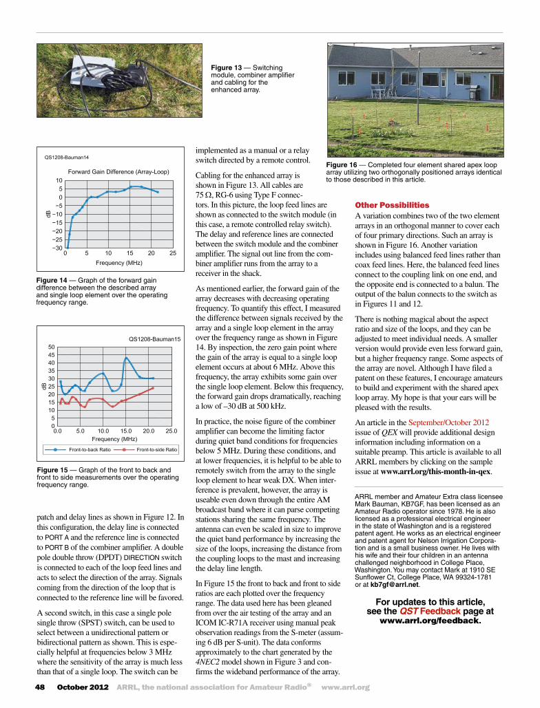
As mentioned earlier, the forward gain of the array decreases with decreasing operating frequency. To quantify this effect, I measured the difference between signals received by the array and a single loop element in the array over the frequency range as shown in Figure 14. By inspection, the zero gain point where the gain of the array is equal to a single loop element occurs at about 6 MHz. Above this frequency, the array exhibits some gain over the single loop element. Below this frequency, the forward gain drops dramatically, reaching a low of –30 dB at 500 kHz.
In practice, the noise figure of the combiner amplifier can become the limiting factor during quiet band conditions for frequencies below 5 MHz. During these conditions, and at lower frequencies, it is helpful to be able to remotely switch from the array to the single loop element to hear weak DX. When inter-ference is prevalent, however, the array is useable even down through the entire AM broadcast band where it can parse competing stations sharing the same frequency. The antenna can even be scaled in size to improve the quiet band performance by increasing the size of the loops, increasing the distance from the coupling loops to the mast and increasing the delay line length.
In Figure 15 the front to back and front to side ratios are each plotted over the frequency range. The data used here has been gleaned from over the air testing of the array and an ICOM IC-R71A receiver using manual peak observation readings from the S-meter (assum-ing 6 dB per S-unit). The data conforms approximately to the chart generated by the 4NEC2 model shown in Figure 3 and con-firms the wideband performance of the array.
Figure 13 — Switching module, combiner amplifier and cabling for the enhanced array.
Figure 14 — Graph of the forward gain difference between the described array and single loop element over the operating frequency range.
Figure 15 — Graph of the front to back and front to side measurements over the operating frequency range.
patch and delay lines as shown in Figure 12. In this configuration, the delay line is connected to PORT A and the reference line is connected to PORT B of the combiner amplifier. A double pole double throw (DPDT) DIRECTION switch is connected to each of the loop feed lines and acts to select the direction of the array. Signals coming from the direction of the loop that is connected to the reference line will be favored.
A second switch, in this case a single pole single throw (SPST) switch, can be used to select between a unidirectional pattern or bidirectional pattern as shown. This is espe-cially helpful at frequencies below 3 MHz where the sensitivity of the array is much less than that of a single loop. The switch can be
Figure 16 — Completed four element shared apex loop array utilizing two orthogonally positioned arrays identical to those described in this article.
Other PossibilitiesA variation combines two of the two element arrays in an orthogonal manner to cover each of four primary directions. Such an array is shown in Figure 16. Another variation includes using balanced feed lines rather than coax feed lines. Here, the balanced feed lines connect to the coupling link on one end, and the opposite end is connected to a balun. The output of the balun connects to the switch as in Figures 11 and 12.
There is nothing magical about the aspect ratio and size of the loops, and they can be adjusted to meet individual needs. A smaller version would provide even less forward gain, but a higher frequency range. Some aspects of the array are novel. Although I have filed a patent on these features, I encourage amateurs to build and experiment with the shared apex loop array. My hope is that your ears will be pleased with the results.
An article in the September/October 2012 issue of QEX will provide additional design information including information on a suitable preamp. This article is available to all ARRL members by clicking on the sample issue at www.arrl.org/this-month-in-qex.
For updates to this article, see the QST Feedback page at
www.arrl.org/feedback.
ARRL member and Amateur Extra class licensee Mark Bauman, KB7GF, has been licensed as an Amateur Radio operator since 1978. He is also licensed as a professional electrical engineer in the state of Washington and is a registered patent agent. He works as an electrical engineer and patent agent for Nelson Irrigation Corpora-tion and is a small business owner. He lives with his wife and their four children in an antenna challenged neighborhood in College Place, Washington. You may contact Mark at 1910 SE Sunflower Ct, College Place, WA 99324-1781 or at [email protected].


![[Array, Array, Array, Array, Array, Array, Array, Array, Array, Array, Array, Array]](https://static.fdocuments.net/doc/165x107/56816460550346895dd63b8b/array-array-array-array-array-array-array-array-array-array-array.jpg)