Experimental investigation of the softening–stiffening ...
Upload
luca-martinelliCategory
view
217download
1
Engineering Structures, Vol. 20, No. 12, pp. 1045–1062, 1998 1998 Elsevier Science Ltd. All rights reserved
Printed in Great BritainPII: S0141-0296(97)00202-2 0141–0296/98 $19.00+ 0.00
The seismic behaviour of steelmoment-resisting frames withstiffening bracesLuca Martinelli, Maria Gabriella Mulas and Federico Perotti
Department of Structural Engineering, Politecnico di Milano, Piazza Leonardo da Vinci 32,20133 Milano, Italy
The present paper deals with the seismic behaviour of steel struc-tures which are designed in the attempt of exploiting the dualcharacteristics of moment resisting frames (MRFs) and concentri-cally braced frames (CBFs) as lateral force resisting systems. Threeprototype frames are studied within the context of Eurocode 8(EC8) provisions; these are MRFs which are traditionally designed,against ultimate seismic actions (ULS), without checking ser-viceability limit state rules (SLS-interstory drift limits). To fulfillthese requirements concentrical braces are inserted in the frames,which are not considered in the collapse resistance of the structuralsystem. The non-linear behaviour of these systems under ultimateseismic environment is studied and compared to the one of theunbraced MRFs. The influence of second order effects is also inves-tigated. 1998 Elsevier Science Ltd. All rights reserved
Keywords: moment-resisting frames, concentrical bracing,dynamic analysis, seismic actions
1. Introduction
The seismic behaviour of moment-resisting frames (MRFs)is mainly affected by two problems, which can be summar-ized as follows.
— As pointed out by experience from the Northridgeearthquake1 and by subsequent experimental research,beam-to-column welded connections can develop cata-strophic failures, i.e. brittle without prior ductile behav-iour, before the beam can attain its plastic moment.Even though neither partial nor total collapse occurredin the damaged frames during the Northridge event,these failures, which are essentially due to triaxialloading in the connection zone2, can obviously affectthe MRF behaviour under strong seismic conditions.
— Excessive lateral deformability of unbraced frames canlead to untolerable non-structural damage under mod-erate earthquakes.
Extensive experimental and numerical research ispresently devoted to the first of the quoted aspects2–5. Asto the second, modern codes, such as Eurocode 86 (EC8 inthe following), prescribe very strict deformation (interstorydrift) limits which, in many cases, actually control struc-tural design, leading to the choice of structural elements
1045
which are largely oversized in terms of resistance; due toductility and overstrength conditions, the members oversiz-ing, in turn, results in significant and somehow not justifiedincrease in size, complexity (and thus cost) of connections.
The problem of lateral stiffness can be effectively solved,on the other hand, by employing concentrically bracedframes (CBFs) to absorb seismic forces; the inelasticbehaviour of such structural systems under severe earth-quake conditions, however, is questioned. In fact, energydissipation in CBFs almost completely relies on the cyclicbehaviour of diagonal braces, which can show significantdegradation of stiffness and strength, and thus in dissipationcapability. For this reason code provisions6,7 tend to pre-scribe for CBFs design very strict rules, which can be sum-marized as follows:
(a) design forces higher than the ones for MRFs (lowerbehaviour coefficients);
(b) low slenderness ratios for diagonal members;(c) neglect of the resistance of the compressed diagonal
(in EC8), regardless of the bar slenderness;(d) strict overstrength conditions for the design of the diag-
onal end connections, which become even more severewhen combined with rules in (a) and (b), leading toquite heavy bracing members.

1046 Seismic behaviour of steel moment-resisting frames with stiffening braces: L. Martinelli et al.
Again, due to the increase in connections design actions,application of the quoted provisions results in a significantreduction of the cost-effectiveness of CBFs as seismicresistant structural systems.
Based on the above considerations, this research workfocuses attention on lateral force resisting systems whichare designed in the attempt of exploiting the dual character-istics of MRFs and CBFs. More precisely, the behaviourof concentrically braced moment-resisting frames is investi-gated, which are different from usual dual systems (e.g. asconsidered in EC8) in that the braces are intended just aslateral stiffeners under serviceability conditions.
To this aim three prototype MRFs are studied within thecontext of EC8 provisions; the frames are traditionallydesigned against ultimate seismic actions (ULS), withoutchecking serviceability limit state rules (SLS-interstorydrift limits). To fulfill these requirements concentricalbraces are then introduced, which are not considered in thecollapse resistance of the structural system and, for this rea-son, do not comply with EC8 provisions in terms of slen-derness limits and resistance against ULS actions. Partialneglect of overstrength conditions for braces connectionsis also considered; summing up, the diagonals which areintroduced in the design can be regarded as low-resistanceand low-ductility braces.
A possible drawback of this design concept, which willbe termed as RFSB (Resisting Frame-Stiffening Bracing)in the following, lies in the possibility of early failure of anumber of braces during the ULS event, with subsequentactivation of unfavourable and unpredictable dynamicbehaviour.
To investigate the seismic response of systems designedaccording to the RFSB concept, in the present researchwork the non-linear behaviour of the structures at studyunder ULS conditions is analysed and compared to that ofthe unbraced MRFs. The influence of second order effectson the response of all systems is also investigated.
In the paper the procedures adopted in the dynamic non-linear analyses are described along with the resultsobtained. Section 2 is devoted to a description of the non-linear frame element; since the model has already beenpresented in a previous work8, here attention is mainlyfocused on the modifications which have been recentlymade to the adopted hysteretic relation for inelastic zones.Section 3 reports a brief description of the non-linear trusselement used for brace modelling (described in detail inReferences 9, 10). In section 4 the procedures adopted inthe dynamic step-by-step non-linear analyses are sketched;in Sections 5 and 6, finally, the assumptions made in thedesign and the results obtained in the analysis of the quotedsystems will be described.
2. The non-linear beam element
In the non-linear dynamic analysis of large frames loadedby strong earthquakes the need arises of a beam elementthat, while being simple enough not to be computationallyprohibitive, can represent adequately the experimentalbehaviour. Therefore, in the present work a global model,previously derived by the authors8, has been adopted: a sin-gle element is introduced for each beam. Structural analysisand experimental observation show that the critical areasof plane MRFs are usually located close to the beam–column joint interfaces, where inelastic phenomena start:in the case of steel structures the experimental evidence11
shows that phenomena as low-cycle fatigue and local buck-ling prevent the spreading of plasticization. The adoptedmodel is based upon a lumped-plasticity formulation,known in the literature as “one-component” model12; it issupposed that the nonlinear effects, due to bending alone,do not spread along the length of the beam, being ideallyconcentrated over a part of zero length, the plastic hinge,forming at each end of the beam. Plastic hinges are deemedto represent the non-linear behaviour of critical zones, andtheir constitutive relation, in terms of moment and rotation,is directly derived from experimental data. A brief presen-tation of the element is reported in the following, togetherwith the modifications introduced, in the present work, tothe hysteretic relation of plastic hinges.
The beam model, depicted inFigure 1, is composed ofa central part, of length L equal to the length of the elementto be modelled, linked in series (at each end) with an hingehaving a rotational spring, called a plastic hinge in the fol-lowing. The central part has elastic behaviour; plastichinges, following independent hysteretic relations, haverigid-plastic behaviour. The element flexibility matrix,referred to the degrees of freedom ofFigure 1, namely therotation of the two ends relative to the chord, is easily foundby summing up contributions of beam and plastic hinges:
[ f] = [ fb] + [ fs] = Ffb11fb12
fb21fb22
G + Ffs10
0 fs2
G. (1)
Axial flexibility, not being considered here, is uncoupledfrom flexural one, and has the standard expression for elas-tic bars. Shearing deformation is accounted for by givingthe appropriate value to the coefficients in the expressionof [ fb]. The local stiffness tangent matrix [k] is determinedby inversion of the flexibility matrix [f] and the stiffnessmatrix [K] of the element, taking into account also rigidbody modes (i.e. vertical translations), is obtained by trans-forming [k] according to a suitable transfer matrix [T]:
[K] = [T]T[k][ T]. (2)
The presence of a beam-to-column rigid joint havingfinite dimensions can be modelled through an appropriatechoice of matrix [T]; this matrix can be extended to accountfor deformable joints, as it has been done by Mulas andGaravaglia13, without any modification to the element for-mulation.
To take into account second order effects in columns astandard geometric stiffness matrix is added to elastic stiff-ness. The axial load value entering this matrix is updatedat the beginning of each step, while the computation ofinternal restoring forces is performed on the basis of axialload value computed at the end of the iteration.
Figure 1 Non-linear beam element
Seismic behaviour of steel moment-resisting frames with stiffening braces: L. Martinelli et al. 1047
As it was already pointed out by Giberson12, a problemarises with the adoption of this model, related to the statedetermination of the element (computation of internalrestoring forces); backtracking and overshooting phenom-ena are unavoidable in the non-linear range if the simpleformulation in terms of flexibility is used to determineinternal forces in the element. Moreover, unbalancedmoments, which cannot be eliminated and accumulate dur-ing the analysis, arise at spring–beam interface. The sol-ution to this problem has been found in the adoption, at theelement level, of an event-to-event strategy8, having definedas an event, in a plastic hinge, the change in the tangentstiffness of the moment-rotation relation. In this way thehysteretic relations of plastic hinges are followed correctlyand no unbalanced moments are introduced at springs–beam interface, while unbalanced forces act only in pointswhere nodal displacements are defined, i.e. along globalcoordinates; structural equilibrium can be achieved by astandard Newton–Raphson procedure.
2.1. The hysteretic relation for plastic hingesThe sought moment-rotation relation for the plastic hingehas been directly derived, through a change of referenceglobal parameters, from a constitutive model15 (given interms of force and displacement at the free end of a cantil-ever beam) describing the experimental non-linear behav-iour of a cantilever beam subjected to cyclic loading14. Thebeam experimental setting is schematically shown inFig-ure 2; for reasons inherent to the geometry of the testingmachine, the cantilever beam having lengthl, is composedof a deformable part of lengthld and of a rigid part oflength lr. A force F is applied on the specimen top, whilethe displacementx is read at the top of the deformable part.
The typical F–x experimental diagram has been rep-resented with a trilinear constitutive model15. The primarycurve, symmetric, is bilinear, and is completely defined bythe elastic stiffnessa0, the initial yielding stiffnessb0, andby the yielding point (Fy, xy). The generic hysteresis cycle
Figure 2 Scheme of experimental test on cantilever members
is represented by a trilinear curve (Figure 3): the stiffnessdegraded reloading branch and the yielding branch atithcycle have reduced stiffnessai and bi respectively, toaccount for damage due to buckling of compression flanges,fatigue and fracture. Unloading always takes place with theelastic stiffnessa0; reloading following a partial unloadingis elastic up to the unloading point. The amount of stiffnessreduction, and therefore of damage, is related to the semi-cycle maximum amplitudexmax (seeFigure 3) previouslyexperienced, the latter being defined as the difference, inabsolute value, between the value ofx for F = 0 and thevalue reached at the following reversal point. The para-meterxmax is defined (and consequently updated) only for“complete” cycles, where the reversal point lies on theyielding branch (Figure 3). By denoting F = F/Fy,x = x/xy, and with a and b the stiffnessa and b in the F–x plane, the following relations hold14:
ai = a0(1 − H1 xmax) (3)
bi = b0(1 − H2 xmax). (4)
The onset of yielding in the generici-th cycle will occur,on positive and negative side respectively, at a valueF +
y
or F−y given by:
F +y = Fy + DFy (5)
F−y = − Fy − DFy. (6)
In equations (5) and (6)DFy is the translation undergoneby the yielding branch with respect to the initial valueFy;this translation is expressed in non-dimensional form as:
DFy = H3 xmax − H4 xb − Oi − 1
j = 1
H5 xj. (7)
In equation (7) the first term accounts for isotropic strainhardening, the second one for the loss of strength due to
Figure 3 Analytical force vs displacement hysteretic law

1048 Seismic behaviour of steel moment-resisting frames with stiffening braces: L. Martinelli et al.
buckling of compression flanges and the third one for dam-age due to low-cycle fatigue. The non-dimensional, posi-tive, coefficients H1 to H5 have been set14 from the experi-mental curves. The non-dimensional displacementxb is the“buckling effective displacement”, defined as
xb = xmax − xfb $ 0 (8)
xfb being the absolute value of the non-dimensional semi-cycle amplitude preceding the first occurrence of localbuckling. The parameterxmax appearing in the previousequations cannot exceed an upper limitxlim, depending onthe cross-section geometry and set on the basis of experi-mental data.
This constitutive model has been expressed in terms ofthe momentM at the bottom of the beam and of the rotationb undergone by the chord of the deformable part of thebeam, due to the inelastic partxp of the displacementx;with reference toFigure 2 we obtain:
M = Fl (9)
b =xp
ld. (10)
In a non-dimensional form the above parametersbecome:
M =MMy
(11)
b =b
by=
xp
xy= xp. (12)
The valuesMy and by are obtained from equations (9)and (10) respectively, whenF = Fy andxp = xy. The rotationby is only a reference value and has not the physical mean-ing of rotation in the plastic hinge whenM = My, sincebis identically zero in the elastic range up toFy. Denotingby k the non-dimensional tangent stiffness in theF–x planeit can be shown8 that the following relation holds:
DM =k
1 − kDb. (13)
From this equation it is apparent that in the elastic range(k = 1) the plastic hinge has an infinite stiffness, i.e. a rigidbehaviour. An appropriate transformation equation, notreported here, can be derived to relate the cycle amplitudesxmax and bmax.
2.2. Rules governing the cyclic behaviour under randomloading historiesA problem arises with the adoption of this constitutivemodel, when adopted to represent random loading historiesas those generated by earthquakes. In fact, while in theexperimental loading histories all the reversal points lie inthe plastic branch, in the random histories this is no longertrue. If the reloading slope is the same in both cases, areversal point lying close to the value of zero force canoriginate a reloading branch where, outside the yieldingrange, the maximum value of plastic deformation is
Figure 4 Unsatisfactory behaviour of former hysteretic law
exceeded, as shown inFigure 4. Moreover, from this figureis apparent the difference between the unloading slope andthe subsequent reloading slope on the same positive sideof the diagram, difference that is not justifiable if the excur-sion in the negative side has been very limited.
To overcome these inconsistencies the constitutiverelation has been modified with the introduction of twofocal points governing the reloading paths; in the followingthe use of these points will be illustrated with reference toFigure 5. The reversal pointA, lying on the plastic branch,is the first focal point; it originates an elastic unloadingbranch up to the pointB of zero force. WhenB is reached
Figure 5 Proposed modification to hysteretic law

Seismic behaviour of steel moment-resisting frames with stiffening braces: L. Martinelli et al. 1049
equations (3), (4), (6) and (7) are employed to determinethe subsequent (updated) reloading and plastic branch stiff-ness values, and the yielding pointC on the negative side,second focal point. A reversal point lying on the lineBC,e.g. pointD, will determine an unloading, elastic branchup to point E; no updating is performed atE becauseDdoes not belong to a yielding branch; reloading on theopposite side will take place along lineEA. The yieldingbranch on positive side is entered at pointA and the pre-vious yielding stiffness is restored. A reversal point on lineEA, e.g. pointF, will analogously determine an unloading,elastic, branch up to pointG; again, no updating is perfor-med atG, and reloading will follow the lineGC. Intermedi-ate reversal points, asD andF, determine only the startingpoint of reloading branches; the final points of thesebranches are always the two focal points. However, if theunloading pathsFG or DE are not completed up to thepoint of zero force, and a reloading happens on these lines,this will be elastic up to pointsF and D respectively, andthe previous reloading lines (EA andBC) will be resumed.
With these modifications the stiffness determinedthrough equation (4) represents the minimum value ofreloading stiffness, and limits the portion ofF–x plane thatcan be reached during the loading history.
3. The non-linear truss element
The model here adopted for the behaviour of bars subjectedto cyclic axial force (see References 9, 10) is based on thediscretization of the truss member into two rigid elementsconnected by a deformable cell [Figure 6a]; the model con-figuration is described by the cell relative rotationf andby the relative end displacement due to axial elongation,namedun. The elastic properties of the cell (flexural andaxial stiffness) are set in order to match the Euler criticalload and the axial stiffness of the continuous bar.
The behaviour of the cell in the non linear range is
Figure 6 Non-linear truss element
characterized on the basis of the properties of the crosssection of the bar; this is discretized into a finite numberof strips [seeFigure 6b] which are characterized by area,distance from section centroid, residual stress and yieldlimit. For each configuration change (Df, Dun), the defor-mation increments in the section strips are computedaccording to the following hypotheses:
— axial deformations are uniformly spread along thebar axis;
— plane sections remain plane;— the ratio of the curvature to the elastic limit curvature
in the midspan section of the bar equals the ratio of therotation to the elastic limit rotation of the model cell.
Given the strain increment in each strip and the constitut-ive relation (here taken as elastic–plastic with kinematichardening) the changes in the internal bending moment andaxial forces
DM = DM(Df, Dun); DN = DN(Df, Dun) (14)
can be computed by a simple summation process over thestrips. Note that a more sophisticated constitutive law,accounting for isotropic hardening as well as for local dam-age, was inserted in the model in a previous work10; how-ever, it was subsequently demonstrated16 that, at the duc-tility levels implied by usual q-factors and for the (limited)number of significantly inelastic cycles imposed by seismicactions to this type of structures, the simple kinematic hard-ening model can give reliable results in terms of overallstructural response, since the brace behaviour is largelydominated by inelastic global buckling.
Based upon the above criteria, the bar model allows forthe incremental description of the relationship between the(total) relative end displacementDu and the axial forceDN;

1050 Seismic behaviour of steel moment-resisting frames with stiffening braces: L. Martinelli et al.
this relationship can be obtained, at each step, according tothe following iterative procedure.
(a) Given the value ofDu two trial values ofDf are chos-en.
(b) The value ofDun is computed, for each value ofDf,satisfying the incremental second-order compatibilityequation
Du =L8
D2f +L4
(f + f0) Df + Dun (15)
where f is the current rotation andf0 is the valueleading to the initial value of bar midspan out-of-straightness v0.
(c) For each pair of values (Df, Dun), the changes ininternal cell bending moment and axial force (14) arecomputed as summarized before.
(d) The equilibrium errorDe is computed, for each pair(DM, DN), from the incremental equation
De = DM −L4
[Df (N + DN) + DN (f + f0)] (16)
(e) Given the two computed values ofDe a new value ofDf is chosen according to the secant rule and theanalysis goes back to step (b), unless the equilibriumerror lies within a prescribed tolerance.
The model validation has been obtained through a seriesof experimental test; the test results and the comparisonwith numerical simulations are described in detail in Refer-ences 9, 10.
4. Non-linear analysis of dynamic response toseismic excitation
In the case of single-component seismic excitation, theequations of motion of an N-degree-of-freedom systemshowing material non-linearities can be written in thematrix form
[m]{ v} + [ c]{ v} = { R} − [m]{ r} a(t) (17)
where [m] and [c] are respectively the inertia and dampingmatrices, {v} is the configuration vector, {R} is the vectorof the generalized components of internal restoring forces,{ r} is a vector having unit coefficients along those coordi-nates which act in the same direction as the excitation andzero coefficients elsewhere anda(t) is the ground acceler-ation.
The solution of the non-linear equations of motion havebeen carried on by means of the step-by-step techniquedescribed in Reference 16; this is an implicit procedurebased upon classical solution strategies such as the New-mark method for time integration and the ModifiedNewton–Raphson (MNR) iterative algorithm for equilib-rium correction (see Reference 17). The HHT method18 isalso employed to add numerical damping to high-fre-quency oscillations.
In the performed dynamic analyses horizontal base accel-eration was considered, consisting of a set of five artificialaccelerograms which are compatible with the EC8-curve“b” elastic spectrum. These time-histories, which were gen-
erated according to the technique described in Reference10, are consistent with the hypothesis that the ground accel-eration is an uniformly modulated non-stationary process.The modulating function has an initial parabolic rise, con-stant amplitude between 0.5 and 10 s and a subsequentexponential decay.
5. Dynamic analysis of RFSB systems underseismic excitation
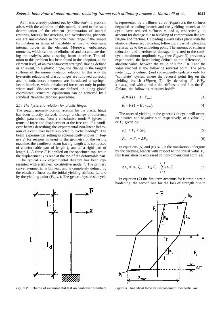
5.1. Frames description and design proceduresThe overall dimensions and design loads of the systems atstudy are depicted inFigure 7; frame-to-frame spacing isequal to 5 m for frame A and to 7.3 m for frames B andC. Note that these are complete MRFs while in system Athe central bay only has been sized to resist lateral loadsand adjacent spans simply act as vertical load carrying sys-tems. Design criteria which are common to all systems arethe following.
— Flexural members (beams and columns) are designedagainst ULS design seismic action as specified by EC86
for a soil profile type B, a damping ratio of 3% and abehaviour factorq = 6; design peak ground acceler-ations (a) are given inTable 4.
— Concentrical braces are subsequently introduced in thedesign and the combined system is checked, viaresponse spectrum analysis, against the followingrequirements.
(a) Serviceability limit state (SLS) requirements as speci-fied by EC86 as
dr # dhn ; dr = qddegI (18)
wheredr is the interstory drift,h the storey height,n thecoefficient taking account of the lower return period ofthe event associated to the SLS,de is the interstorydrift computed via the ULS design spectrum,qd is thedisplacement behaviour factor andgI the importancefactor. The following values were assumed
d = 0.004, 0.006;n = 2; qd = q = 6; gI = 1 (19)
(b) Ductility requirements for the braces, which werestated as a limit ductility demand of 1.5 under the SLSevent. Note that the limit value was reached for frameA only, while for frames B and C maximum values of1 and 1.2 respectively were attained.
(c) Capacity design requirements for resistance and stab-ility of columns, which were checked against braces’yielding forces.
In computing the response of the combined system thecontribution of the compressed brace is taken into account,as proposed in Reference 10, by multiplying its area by thecoefficient of reduction of the compressive load capacityxas stated by curve “c” in Eurocode 319. This design criterionhas demonstrated to be effective and consistent in the caseof one-storey bracing systems10; for multi-storey systems itcan lead to some “unsafe-side” prediction of response toULS seismic actions. Here it was believed that, within thecontext of a SLS analysis and for predicting “best estimate”interstory drifts, the contribution of compressed bars hadto be considered, even though in a simplified way.
Seismic behaviour of steel moment-resisting frames with stiffening braces: L. Martinelli et al. 1051
Figure 7 A, B, C systems: overall dimensions and design loads
To maintain symmetry, the area of the two diagonal barsat each interstory has been defined, in the dynamic modelused for response spectrum analysis, according to the fol-lowing formula
Ad =Ad(1 + x)
2(20)
whereAd is the gross section of the bars. The tension and
compression design axial forcesNd1, Nd2 in each brace issubsequently computed, on the basis of the valuesNd1 andNd2 resulting from the response of the symmetric model,according to the relations
Nd1 =Nd1 + Nd2
1 + x; Nd2 = xNd1 (21)
Note that two structures, resulting from the interstory

1052 Seismic behaviour of steel moment-resisting frames with stiffening braces: L. Martinelli et al.
drift factor valuesd = 0.004 andd = 0.006, are actuallydesigned for each of the three frames. These structures,however, differ only for the braces sections, while columnsare maintained equal and checked against the capacitydesign requirements resulting from the worst cased = 0.004(stronger braces).
In the design against the ULS seismic event, the standardmulti-modal response spectrum analysis was applied, asspecified by EC86, to frames B and C. For frame A a morerefined procedure based on consideration of collapse mech-anisms was adopted; the procedure, which is described inmore detail in References 8, 20, can be summarized in thefollowing steps.
(1) Preliminary member sizing is based upon the simpli-fied analysis method proposed in EC86; according tothis procedure equivalent static forces are appliedwhich are linearly distributed along the structure heightand whose sum equals the total base shear computedvia the design spectrum and a first natural period esti-mate.
(2) The system of equivalent lateral forces is used to checkthe frame collapse mechanism. The load multiplierspertaining to partial mechanisms ofFigure 8 are com-puted for each storey and members sizes are modifiedby imposing to these values to be larger than the multi-plier corresponding to the activation of the desiredcomplete sidesway mechanism. The latter multiplier iscomputed by taking second-order effects into account.
Note that when the described design procedure was com-pleted, capacity design requirements were checked for col-umns stability under axial forces resulting from yieldingbraces (see point “c” aforementioned); this leads to anincrease in the section size for the first story column, suchthat eventually the collapse mechanism having the mini-mum multiplier was not the desired one but an uncompletemechanism (type “b” inFigure 8) with plastic hinge (PH)formation in columns just above the first floor.
In Tables 1–3floor masses and final member sectionsare summarized for all cases considered; it can be notedthat frame A shows a more marked variation of columnsections with height. Brace sections are built-up with back-to-back channels; it is assumed that brace buckling occursin the frame plane, this being parallel to the channels web.The first natural periods of the three unbraced MRFs arevery similar, with values slightly larger than 2 s.
Figure 8 Storey collapse mechanisms for moment-resisting frame
Finally, the peak ground acceleration (PGA) correspond-ing to the attainment of the resistance of the most stressedelement is evaluated, for all systems, from the elastic spec-trum (EC8-curve “b”) and from the vertical loads; thisvalue is given in the fourth line ofTable 4and is consistentwith a unit behaviour factor. Since in the long and inter-mediate period range a linear law relates, for a given struc-ture, the design PGA and the behaviour factor, the valuesof PGA corresponding to different values of the q-factorwere computed by simple linear scaling and listed inTable4. Note that the PGA values forq = 6 are higher than thedesign valuesa (shown as well inTable 4) due to unavoid-able oversizing of structural elements; this is more evidentfor frames B and C, while frame A is characterized by verylimited overstrength. In computing the values ofTable 4diagonal bars are not taken into account.
5.2. Criteria for non-linear dynamic analysisThe dynamic models used in the numerical analysis wereset according to the following hypotheses and criteria.
— The model mass matrix is obtained, under the hypoth-esis of rigid diaphragm floor behaviour, assuming thatinertia is concentrated at the storey levels.
— The viscous damping matrix is computed, according tothe proportionality assumption, imposing a value of0.03 to the damping factors pertaining to all elastic nor-mal modes.
— The beam model described in section 2 is used tomodel flexural beams; the full plastic moment of thesections is taken as the yielding moment, while theother coefficients describing the hysteretic law of theplastic hinges (PHs) are taken from experimentalresults regarding elements of the same series havingsimilar width-to-thickness ratios.
— The described beam element is employed for columnsmodelling too; this introduces two kinds of approxi-mations. First of all, axial load-bending moment inter-action is neglected and full plastic moments of the col-umn sections are computed on the basis of static axialloads. This approximation, which is usually acceptedfor MRFs due to symmetry properties, can be regardedas reasonable for a braced frame, as the ones here con-sidered, where diagonal members are relatively weakand columns are remarkably stronger due to capacitydesign considerations. Secondly, the coefficients con-trolling the columns PH hysteretic behaviour were

Seismic behaviour of steel moment-resisting frames with stiffening braces: L. Martinelli et al. 1053
Table 1 A system. Floor masses and member sections. Material Fe360
f. l. Masses (kg) Columns Beams Braces
d = 0.004 d = 0.006
1 44 325 HE 340 M HE 280 B 2 UPN 80 2 UPN 402 44 325 HE 340 B HE 280 B 2 UPN 100 2 UPN 653 42 300 HE 300 B HE 260 B 2 UPN 100 2 UPN 504 42 300 HE 300 B HE 240 B 2 UPN 100 2 UPN 405 45 000 HE 280 B HE 240 B 2 UPN 80 2 UPN 306 42 300 HE 260 B HE 220 B 2 UPN 65 2 UPN 30
Table 2 B system. Floor masses and member sections. Material Fe510
f. l. Masses (kg) Outside columns Inside columns Beams Braces
d = 0.004 d = 0.006
1 46 468 HE 260 B HE 320 B IPE 330 2 U 60 × 30 2 U 60 × 302 46 468 HE 260 B HE 320 B IPE 330 2 U 60 × 30 2 U 60 × 303 43 449 HE 240 B HE 300 B IPE 300 2 U 60 × 30 2 U 50 × 254 43 449 HE 240 B HE 300 B IPE 300 2 U 50 × 25 2 U 50 × 255 43 394 HE 220 B HE 280 B IPE 270 2 U 40 × 20 2 U 40 × 206 39 452 HE 220 B HE 280 B IPE 270 2 U 40 × 20 2 U 40 × 20
Table 3 C system. Floor masses and member sections. Material Fe510
f. l. Masses (kg) Outside columns Inside columns Beams Braces
d = 0.004 d = 0.006
1 43 150 HE 300 B HE 340 B IPE 360 2 UPN 50 2 UPN 502 43 150 HE 300 B HE 340 B IPE 360 2 UPN 50 2 UPN 403 41 140 HE 300 B HE 340 B IPE 360 2 UPN 40 2 UPN 404 41 140 HE 280 B HE 320 B IPE 330 2 UPN 40 2 UPN 405 41 140 HE 280 B HE 320 B IPE 330 2 UPN 40 2 UPN 40 × 206 41 140 HE 280 B HE 320 B IPE 330 2 UPN 40 2 UPN 40 × 207 41 140 HE 260 B HE 300 B IPE 300 2 U 40 × 20 2 U 30 × 158 41 140 HE 260 B HE 300 B IPE 300 2 U 30 × 15 2 U 30 × 159 38 550 HE 260 B HE 300 B IPE 300 2 U 30 × 15 2 U 30 × 15
Table 4 A, B, C systems. Non-dimensional design PGA (a) andanalysis PGA vs design q-factor
A B C
a 0.35 0.25 0.35
q a0 (m/s2) a0 (m/s2) a0 (m/s2)
1 0.5985 0.6829 1.13134 2.3941 2.7318 4.52555 2.9927 3.4148 5.65696 3.5912 4.0977 6.78837 4.1898 4.7807 7.91978 4.7883 5.4637 9.0511
taken from experimental tests performed with zeroaxial loads; this assumption was accepted since thelargest part of energy dissipation occurs in beams andbraces. Moreover, it was found that inelastic cyclingin columns is characterized by excursions which arelimited in amplitude and number.
— The non-linear truss element described in section 3 is
employed for the braces; each of them is modelled bymeans of a single element, while the midspan connec-tion is taken into account by assuming an unsupportedlength half the actual diagonal bar length. A “death”option is also implemented in the element, such thatwhenever a brace reaches in tension a specified ulti-mate ductility demand it is removed from the dynamicmodel for the subsequent part of the analysis; ultimateductility valuesmd = 2, 4 and 8 were considered.
5.3. Results of the numerical analysesThe main results obtained from dynamic analyses will bedescribed and discussed in the present section. In the graphsshown in the following the extreme values of responseparameters are plotted versus the actual behaviour factors,which are in turn related to the input PGA as shown inTable 4. This means that, for each value of the behaviourfactor in the range 4# q # 8, the artificial accelerogramswere scaled to a peak value equal to the PGA listed in thequoted Table. In this way the effect of the overstrengthof the studied systems with respect to design conditions ispartially removed from the analysis; it must be also
1054 Seismic behaviour of steel moment-resisting frames with stiffening braces: L. Martinelli et al.
observed, in this respect, that values ofTable 4are mainlygoverned by beams resistance, so that differences in actualoverstrength of columns still affect the comparison amongthe behaviour of the various frames.
The parameters shown to represent the inelastic responseseverity are interstory drifts (ID) and PH rotations. The firstare given in non-dimensional form, i.e. normalized to thestorey height; extremes of IDs are defined as mean valuesover the results obtained for the five input accelerograms.For PH rotations, given in radians, the maximum absolutevalue is first picked up, for each accelerogram, and for eachelement; these values are then averaged over the accelerog-rams. The extreme of these values is then picked up amongelements of the same type (beams or columns) and is called“mean extreme” in the following. The maximum value overthe five accelerograms and over all the elements of the sametype is also computed and termed “overall extreme” value.
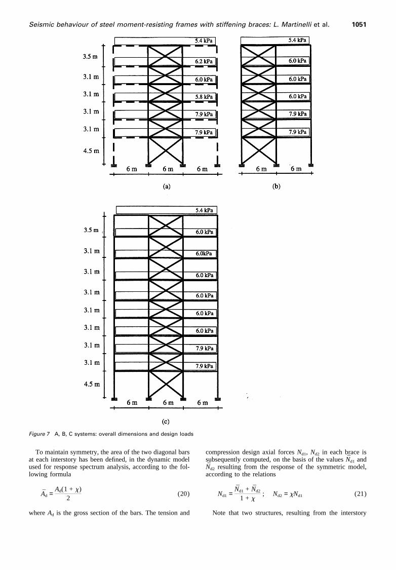
In Figure 9 the influence of second-order effects on theresponse of the unbraced MRFs (simply termed MRFs inthe following comments) is shown in terms of intestory-drift envelopes. For systems A and B (6 stories) the effectis significant only for the highest value considered of thebehaviour coefficient (q = 8); note that no second-ordereffect check was applied in the design of these systems.For system C (9 stories) the effect is significant forq , 5at lower interstories.
From Figure 9 the different behaviour of the studiedframes can also be inferred: system A behaves essentiallyas a cantilever, with ID values growing at higher floors dueto node rotations, while system C response resembles the
Figure 9 Non-dimensional interstory drift vs q-factor. (a) A system. (b) B system. (c) C system. MRF with 2nd ordereffects; ——— MRF
one of a “shear-type” frame, with maximum IDs at lowerstories; frame B shows an intermediate behaviour.
5.3.1. Response of RFSB frame A.In Figures 10–12the interstory drift 3-D plots are given for the RFSB frameA and compared to the results of the MRF (with second-order effects). In each figure the casesd = 0.004 (graph“a”) and d = 0.006 (graph “b”) are given, differing in thebracing sections only. Ultimate braces ductility factorsmd
are respectively equal to 2, 4 and 8 forFigures 10–12. Theresult shows a tendency to form a “soft” first story for thecase d = 0.004 (stiffer braces); this tendency is moremarked for the lower brace ductility values and leads to aresponse envelope which is substantially different from theMRF one. MRF values, however, are exceeded only formd
= 2 and for the lower q-factor values. Second-order effectsare responsible for significant response increase only forsystems showing the “soft-storey” effect (d = 0.004) andfor the higher q-values; otherwise the influence is not welldefined, leading, in some cases, to a more favourablebehaviour.
For the same frame overall extreme values of beam PHrotations are given inFigure 13 for all the cases analysed.It can be seen that the values pertaining to the MRF arenever exceeded by RFSB frames; rotations are larger in thed = 0.006 case (weaker braces), for which they reach theMRF values for the higher q-factors and the lower braceductility values. For the cased = 0.004 beam PH rotationsare always smaller than 0.01 rad. The value of 0.03 whichis indicated by Popov et al.4 as a reasonable maximum

Seismic behaviour of steel moment-resisting frames with stiffening braces: L. Martinelli et al. 1055
Figure 10 Non-dimensional interstory drift vs q-factor. (a) A system d = 0.004. (b) A system d = 0.006. md = 2. MRF with2nd order effects; ——— braced MRF; – – – braced MRF with 2nd order effects
Figure 11 Non-dimensional interstory drift vs q-factor. (a) A system d = 0.004. (b) A system d = 0.006. md = 4. MRF with2nd order effects; ——— braced MRF; – – – braced MRF with 2nd order effects
Figure 12 Non-dimensional interstory drift vs q-factor. (a) A system d = 0.004. (b) A system d = 0.006. md = 8. MRF with2nd order effects; ——— braced MRF; – – – braced MRF with 2nd order effects

1056 Seismic behaviour of steel moment-resisting frames with stiffening braces: L. Martinelli et al.
Figure 13 A system. Overall extreme plastic rotation in beams vs q-factor. (a) d = 0.004. (b) d = 0.006. MRF; MRF + 2ndorder; md = 2; – h – md = 2 + 2nd order; md = 4; – g – md = 4 + 2nd order; md = 8; – s – md = 8 + 2nd order
value of plastic rotation demand for beams is neverexceeded. The influence of brace ductility is well marked,since frames havingmd = 8 show the lowest values of PHrotations practically in all cases. Plots of mean extremevalues (not shown) are very much alike the ones ofFigure13: MRF values are below 0.025 rad and RFSB resultsnever exceed 0.017 rad.
Figure 14 shows overall extremes of columns PHrotations; at a first glance it is evident that MRF valuesare exceeded in most cases by RFSB frames. Neverthelessrotations are small (, 0.008 rad) and grow quite regularlyfor increasing q-factor, except for cased = 0.004 − md =2, for which they are almost constant in the range con-sidered. The influence of brace behaviour is here lessdefined than for beams; as an average, however, brace duc-tility seems to affect in a favourable sense columns inelasticbehaviour. Similar considerations hold for mean extremes,whose maximum values, however, do not exceed 0.003 rad.
Figure 14 A system. Overall extreme plastic rotation in columns vs q-factor. (a) d = 0.004. (b) d = 0.006. MRF; MRF + 2ndorder; md = 2; – h – md = 2 + 2nd order; md = 4; – g – = 4 + 2nd order; md = 8; – s – md = 8 + 2nd order
Looking atFigure 14 it can be also noted how columnPH rotations are very small for the MRF, for which theytend to be one order of magnitude less than beam values;this contrasts with the hypothesis of activation of a sides-way mechanism as the one anticipated in the design.
Further investigation has shown that column PHrotations occur at six sections, i.e. at the basis of both col-umns located at first, second and fifth interstory; inaddition, animation of simulated response shows that, eventhough the six PHs are sometimes simultaneously activated,a true mechanism never forms. This fact, along with thetendency to spreading plastic behaviour in more sections,can explain the low PH rotation values. It must be observed,in this respect, that the design procedure, based upon lin-early distributed horizontal forces, seems to fail in pre-dicting the inelastic response pattern and in governing thecollapse mechanism.
5.3.2. Response of RFSB frame B.Figures summariz-

Seismic behaviour of steel moment-resisting frames with stiffening braces: L. Martinelli et al. 1057
Figure 15 Non-dimensional interstory drift vs q-factor. (a) B system d = 0.004. (b) B system d = 0.006. md = 2. MRF with2nd order effects; ——— braced MRF; – – – braced MRF with 2nd order effects
Figure 16 Non-dimensional interstory drift vs q-factor. (a) B system d = 0.004. (b) B system d = 0.006. md = 4. MRF with2nd order effects; ——— braced MRF; – – – braced MRF with 2nd order effects
ing the main features of the B frame response are given inthe same order as for frame A.
Looking at interstory drift values shown inFigures 15–17 it can be seen, first of all, that the MRF response isnever exceeded. Maximum ID values for RFSB frame Boccur in the case characterized by the higher ID factord =0.006 and the lower brace ductilitymd = 2 [Figure 15b].For this case the influence of second-order effects is alsomost significant. The response pattern is different from theone of frame A, since “soft-storey” effects do not occurand the influence of braces stiffness and strength (d value)does not seem to be very important.
The extreme values of beam PH rotations are given in
Figure 17 Non-dimensional interstory drift vs q-factor. (a) B system d = 0.004. (b) B system d = 0.006. md = 8. MRF with2nd order effects; ——— braced MRF; – – – braced MRF with 2nd order effects
Figure 18 (overall extremes) andFigure 19 (meanextremes). In terms of mean extremes the MRF values arenever exceeded by RFSB frames; overall extremes arelarger than MRF ones for the system having low resistance(d = 0.006) and low ductility (md = 2) braces. Even forthis case, however, PH rotations grow parallel to the MRFones for increasing q-factor and the larger exceedance is ofabout 13%. Second-order effects do not have an importanteffect on beam rotations. It can be also noted that the refer-ence rotation value of 0.03 rad is never exceeded by meanextremes; as to overall extremes, there is one case reachinga PH rotation of 0.037, while other values are smaller than0.035. For the design valueq = 6 the 0.03 value is (slightly)exceeded only in one case.

1058 Seismic behaviour of steel moment-resisting frames with stiffening braces: L. Martinelli et al.
Figure 18 B system. Overall extreme plastic rotation in beams vs q-factor. (a) d = 0.004. (b) d = 0.006. MRF; MRF + 2ndorder; md = 2; – h – md = 2 + 2nd order; md = 4; – g – md = 4 + 2nd order; md = 8; – s – md = 8 + 2nd order
Figure 19 B system. Mean extreme plastic rotation in beams vs q-factor. (a) d = 0.004. (b) d = 0.006. MRF; MRF + 2ndorder; md = 2; –h– md = 2 + 2nd order; md = 4; –g– md = 4 + 2nd order; md = 8; –s– md = 8 + 2nd order
Column PH rotations values, which are shown inFigures20 and21, are about half of beam ones; mean extremes ofRFSB plastic rotations are enveloped by the MRF values,with second-order effects, forq > 5. MRF overall extremesare exceeded in a number of cases, this showing a highervariance of RFSB extreme response. Nevertheless the PHrotation trend for increasingq-factors is very much alike theMRF one also in terms of overall extremes, with maximumvalues exceeding 0.02 only forq = 8. It can be also notedthat second-order effects make column rotations increasepractically in all cases; in one case (d = 0.006,md = 2, q= 8) a twofold increase is obtained. The positive influenceof brace ductility is also well marked while the effect oftheir stiffness and resistance (d value) is not so evident.
As to the PH location, it has been found that they format column bases only, this being consistent with the “strongcolumn–weak girder” design criterion; in addition, the larg-est plastic rotations always occur in the centre column,
which is stiffer than lateral ones. Investigation of the MRFresponse also shows that the complete sidesway mechanismactually forms, as implicitly assumed in the design. In thislight the inelastic behaviour of frame B is very differentfrom the one of frame A, which seemed to be more compli-cate and less predictable, even though showing smaller col-umn PH rotations. This is probably due both to the struc-tural behaviour, which is very different for the single-bayframe A, and to the design process; in fact the procedureused in sizing frame B leads to column sections showingless variation with height and which are characterized byhigher overstrength.
5.3.3. Response of RFSB frame C.Most of the com-ments made about the behaviour of frame B are valid aswell for frame C. Interstory drift values, given inFigures22–24, show a more favourable response of RFSB frameswith respect to the MRF, whose maximum ID is exceeded

Seismic behaviour of steel moment-resisting frames with stiffening braces: L. Martinelli et al. 1059
Figure 20 B system. Overall extreme plastic rotation in columns vs q-factor. (a) d = 0.004. (b) d = 0.006. MRF; MRF + 2ndorder; md = 2; – h – md = 2 + 2nd order; md = 4; – g – md = 4 + 2nd order; md = 8; – s – md = 8 + 2nd order
Figure 21 B system. Mean extreme plastic rotation in columns vs q-factor. (a) d = 0.004. (b) d = 0.006. MRF; MRF + 2ndorder; md = 2; – h – md = 2 + 2nd order; md = 4; –g– md = 4 + 2nd order; md = 8; – s – md = 8 + 2nd order
Figure 22 Non- dimensional interstory drift vs q-factor. (a) C system d = 0.004. (b) C system d = 0.006. md = 2. MRF with2nd order effects; ——— braced MRF; – – – braced MRF with 2nd order effects

1060 Seismic behaviour of steel moment-resisting frames with stiffening braces: L. Martinelli et al.
Figure 23 Non-dimensional interstory drift vs q-factor. (a) C system d = 0.004. (b) C system d = 0.006. md = 4. MRF with2nd order effects; ——— braced MRF; – – – braced MRF with 2nd order effects
Figure 24 Non-dimensional interstory drift vs q-factor. (a) C system d = 0.004. (b) C system d = 0.006. md = 8. MRF with2nd order effects; ——— braced MRF; – – – braced MRF with 2nd order effects
only at first interstory in the case characterized byq = 8,d = 0.006 andmd = 4. The influence of second-order effectsleads to significant response increase only for the highestvalues of theq-factor and for the lowest stories. As in frameB the influence of braces stiffness and strength (d value)does not seem to be very important. The response patternshown in the figures for the RFSB frames does not differsubstantially from the MRF one.
The overall extreme values of beam PH rotations, givenin Figure 25, show values very similar to the ones of frame
Figure 25 C system. Overall extreme plastic rotation in beams vs q-factor. (a) d = 0.004. (b) d = 0.006. MRF; MRF + 2ndorder; md = 2; – h – md = 2 + 2nd order; md = 4; – g − md = 4 + 2nd order; md = 8; – s – md = 8 + 2nd order
B with peak values not exceeding 0.037 rad; for meanextremes (not shown) maximum values are smaller than0.03 rad. RFSB rotations, however, are in many cases largerthan MRF ones, even though forq > 6 the MRF valueswith second-order effects are rarely exceeded. The effectsof the brace ductilitymd and brace strength, governed byd, do not seem to be very significant for beam PH rotations.
Looking at column PH rotations, given inFigure 26 interms of overall extremes, it can be seen that the MRFvalues with second-order effects are rarely exceeded. Here
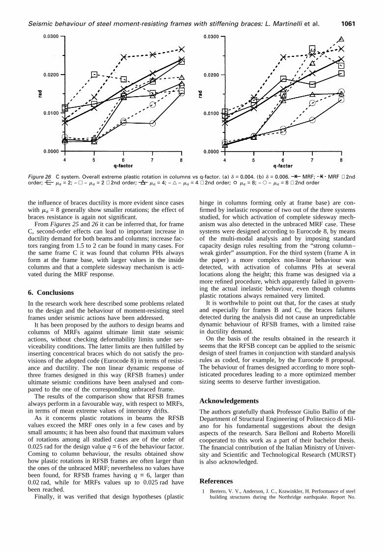
Seismic behaviour of steel moment-resisting frames with stiffening braces: L. Martinelli et al. 1061
Figure 26 C system. Overall extreme plastic rotation in columns vs q-factor. (a) d = 0.004. (b) d = 0.006. MRF; MRF + 2ndorder; md = 2; – h – md = 2 + 2nd order; md = 4; – g – md = 4 + 2nd order; md = 8; – s – md = 8 + 2nd order
the influence of braces ductility is more evident since caseswith md = 8 generally show smaller rotations; the effect ofbraces resistance is again not significant.
FromFigures 25and26 it can be inferred that, for frameC, second-order effects can lead to important increase inductility demand for both beams and columns; increase fac-tors ranging from 1.5 to 2 can be found in many cases. Forthe same frame C it was found that column PHs alwaysform at the frame base, with larger values in the insidecolumns and that a complete sidesway mechanism is acti-vated during the MRF response.
6. Conclusions
In the research work here described some problems relatedto the design and the behaviour of moment-resisting steelframes under seismic actions have been addressed.
It has been proposed by the authors to design beams andcolumns of MRFs against ultimate limit state seismicactions, without checking deformability limits under ser-viceability conditions. The latter limits are then fulfilled byinserting concentrical braces which do not satisfy the pro-visions of the adopted code (Eurocode 8) in terms of resist-ance and ductility. The non linear dynamic response ofthree frames designed in this way (RFSB frames) underultimate seismic conditions have been analysed and com-pared to the one of the corresponding unbraced frame.
The results of the comparison show that RFSB framesalways perform in a favourable way, with respect to MRFs,in terms of mean extreme values of interstory drifts.
As it concerns plastic rotations in beams the RFSBvalues exceed the MRF ones only in a few cases and bysmall amounts; it has been also found that maximum valuesof rotations among all studied cases are of the order of0.025 rad for the design valueq = 6 of the behaviour factor.Coming to column behaviour, the results obtained showhow plastic rotations in RFSB frames are often larger thanthe ones of the unbraced MRF; nevertheless no values havebeen found, for RFSB frames havingq = 6, larger than0.02 rad, while for MRFs values up to 0.025 rad havebeen reached.
Finally, it was verified that design hypotheses (plastic
hinge in columns forming only at frame base) are con-firmed by inelastic response of two out of the three systemsstudied, for which activation of complete sidesway mech-anism was also detected in the unbraced MRF case. Thesesystems were designed according to Eurocode 8, by meansof the multi-modal analysis and by imposing standardcapacity design rules resulting from the “strong column–weak girder” assumption. For the third system (frame A inthe paper) a more complex non-linear behaviour wasdetected, with activation of columns PHs at severallocations along the height; this frame was designed via amore refined procedure, which apparently failed in govern-ing the actual inelastic behaviour, even though columnsplastic rotations always remained very limited.
It is worthwhile to point out that, for the cases at studyand especially for frames B and C, the braces failuresdetected during the analysis did not cause an unpredictabledynamic behaviour of RFSB frames, with a limited raisein ductility demand.
On the basis of the results obtained in the research itseems that the RFSB concept can be applied to the seismicdesign of steel frames in conjunction with standard analysisrules as coded, for example, by the Eurocode 8 proposal.The behaviour of frames designed according to more soph-isticated procedures leading to a more optimized membersizing seems to deserve further investigation.
Acknowledgements
The authors gratefully thank Professor Giulio Ballio of theDepartment of Structural Engineering of Politecnico di Mil-ano for his fundamental suggestions about the designaspects of the research. Sara Belloni and Roberto Morellicooperated to this work as a part of their bachelor thesis.The financial contribution of the Italian Ministry of Univer-sity and Scientific and Technological Research (MURST)is also acknowledged.
References1 Bertero, V. V., Anderson, J. C., Krawinkler, H. Performance of steel
building structures during the Northridge earthquake. Report No.

1062 Seismic behaviour of steel moment-resisting frames with stiffening braces: L. Martinelli et al.
UCB/EERC-94/09, EERC, University of California at Berkeley,1994.
2 Roeder, C. W. and Foutch, D. A., Experimental results for seismicresistant steel moment frame connections,J. Struct. Engng, ASCE1996,122 (6), 581–588
3 Chen, S. J., Yeh, C. H. and Chu, J. M., Ductile steel beam-to-columnconnections for seismic resistance,J. Struct. Engng, ASCE1996,122(11), 1292–1299
4 Popov, E. P., Blondet, M., Behavior of large steel beam-column con-nections. From Report No. UCB/EERC-96/01, University of Califor-nia at Berkeley, 1996:155–162.
5 Yang, T. S., Popov, E. P., Analytical studies of pre-Northridge steelmoment-resisting connections. From Report No. UCB/EERC-96/01,University of California at Berkeley, 1996:227–234.
6 Eurocode No. 8, Common unified rules for structures in seismicregions, ENV, 1998-1-1, 1994.
7 Recommended lateral force requirements and commentaries, Seis-mology Committee, Structural Engineering Association of California,Sacramento, CA 1990.
8 Martinelli, L., Mulas, M. G. and Perotti, F., The seismic responseof concentrically braced moment-resisting steel frames,EarthquakeEngng Struct. Dynam.1996,25, 1275–1299
9 Ballio, G. and Perotti, F., Cyclic behaviour of axially loaded mem-bers: numerical simulation and experimental verification,J. Con-struct. Steel Research1987,7, 3–41
10 Perotti, F. and Scarlassara, G.P., Concentrically braced steel framesunder seismic actions: non-linear behaviour and design coefficients,Earthquake Engng Struct. Dynam.1991,20, 409–427
11 Ballio, G. and Castiglioni, C. A., Seismic behaviour of steel sections,J. Construct. Steel Research1994,29, 21–54
12 Giberson, M. F., Two nonlinear beams with definition of ductility,ASCE, J. Struct. Div.1969,95 (ST2), 137–157
13 Mulas, M. G., Garavaglia, E. The effect of joint deformations on steelplane frames behaviour. In: Proc. of Intl. Conference on Advanceson Steel Structures, vol. I. Hong-Kong, 1996:189–194.
14 Castiglioni, C. A., Di Palma, N. and Moretta, E., A trilinear constitut-ive model for the seismic analysis of steel structures,CostruzioniMetalliche1990,2, 80–96
15 Castiglioni, C. A. and Di Palma, N., Steel members under cyclicloads: numerical modelling and experimental verifications,Costru-zioni Metalliche1988,6, 3–27
16 Perotti, F., De Amici, A. and Venturini, P., Numerical analysis anddesign implications of the seismic behaviour of one-storey steel brac-ing systems,Engineering Structures1996,18 (2), 162–178
17 Argyris J, Mlejnek H-P. Dynamics of structures. Amsterdam: NorthHolland, 1991.
18 Hilber, H. M., Hughes, T. J. R. and Taylor, R. L., Improved numeri-cal dissipation for time integration algorithms in structural dynamics,Earthquake Engng Struct. Dynam.1977,5, 283–292
19 Eurocode No. 3: Common unified rules for steel structures, ENV1993-1-1, 1993.
20 Martinelli, L., Mulas, M. G., Perotti, F. The behaviour of multi-storeyconcentrically braced steel frames under seismic excitations. Techni-cal Report n. 1/96, Structural Engineering Department, Politecnicodi Milano, 1996.