
THE SECRETOF TU I G FRETTED INSTRUMENTS
13
THE SECRET OF TU I G FRETTED INSTRUMENTS
Transcript of THE SECRETOF TU I G FRETTED INSTRUMENTS

THE SECRETOF TU I G FRETTED INSTRUMENTS

THE SECRET OF TUNING FRETTED INSTRUMENTS
Guide for the Experienced Craftsman Here is the experienced craftsmen 's guide to the use of the CONI\J STROBOTUNER and COf\IN STROBOCOf\IN in building and repairing instruments. This booklet is not a general repair manual. It is assumed that the reader already has knowledge of repair techniques. procedures, tools. etc. Instead. this booklet shows you how to use the CONN STROBOTUNER and CONN STROBOCONN to help you repair. adjust, and construct fretted instruments.
Both pieces of equ ipment electronically translate sound into visual images, so you have a sure way to tune components, adjust intonation. and check fret position and bridge location.
Before you proceed. however. it is important to read the STROBOTUNER or STROBOCOf\IN "Owner's Manual" as well as the booklet, "Making Sense Out of Cents," which describes frequency, intervals, scales and cents . Both are available from C. G. Conn, Oak Brook. Illinois.
Acknowledgment
We wish to acknowledge Roger H. Siminoff who authored the information in th is book.

THE SECRET OF TUNING FRETTED INSTRUMENTS
Guide for the Experienced Craftsman Here is the exper ienced craftsmen 's guide to the use of the CONN STROBOTUI\IER and CONN STROBOCONN in building and repairing instruments. This booklet is not a general repair manual. It is assumed that the reader already has knowledge of repair techniques, procedures, tools, etc. Instead , this booklet shows you how to use the COI\IN STROBOTUNER and CONN STROBOCONN to help you repair, adjust, and construct fretted instruments.
Both pieces of equipment electronically translate sound into visual images, so you have a sure way to tune components, adjust intonation, and check fret position and bridge location. Before you proceed, however, it is important to read the STROBOTUNER or STROBOCONN "Owner's Manual " as well as the booklet, "Making Sense Out of Cents," which describes frequency, intervals, scales and cents . Both are available from C. G. Conn, Oak Brook, Illinois.
Acknowledgment
We wish to acknowledge Roger H. Siminoff who authored the information in this book.

THE SECRET OF TUNING FRETTED INSTRUMENTS
Table ofContents Part I-The Strobotuner
The relationship of many parts 3 Preparation 3 Locating the bridge 3 Correcting adjustable bridges 4 Correcting fixed bridges .4 Other adjustments . . . . . . . . .. . 5 Making a new insert for a fixed bridge 5 Correcting the slot of a fixed br idge 6 String height or action 6 Checking fret location 6 Fret height 7 Creating a new scale length 7 Relocat ing a fixed bridge 7
Part II-The Stroboconn Operation 8 Additional equipment 8 Tuning mandolin sounding boards 8 Tone bars 8 Tuning guitar sounding boards 9 Sound holes 9 Tuning frame 9 Tuning note 9 Notes 10-12 Conn Publ ications and Accessories 13

The Strobe Equipment
The STROBOTUNER, a single wheel strobe device, is ideal for checking intonation and fret location . Simply turn the selector knob on the STROBOTUNER to set " target" notes or frequencies. Adjust the fretted instrument until you reach the target note. In this case, you 're working from the STROBOTUNER to the instrument.
Conn Strobotuner-; Model ST-11 (110V, 60Hz) Model ST-12 (220V, 50Hz )
The 12-wheel STROBOCONN is ideal for adjusting air chambers and tone bars because you must search for a note to which that part of the instrument is tuned . As you adjust the instrument, you can observe the change in notes or frequency as it moves through the frequency range-from wheel to wheel-until it reaches the desired level. In this case you're working from the instrument to the STROBOCONN.
Conn Stroboconn ", Model 6T-5
2

Part I-The Strobotuner
The Relationship of Many Parts Because you are deali ng with sensi tive and delica te adjustments, it is important for you to understand that the re is a great interaction between all of the elements of a str inged musical instrument. For example , finding the true position of a bridge also requires checki ng the accurate location of the 12th fret . Alth ough you can generalize where the 12th fret should be, by measuring half of the distance between the br idge and nut, you can't det ermin e the true br idge posit ion unless you know what the distance should be betwe en the nut, all of the frets. the br idge, and the strings.
Preparation To tune the instrument to pitch , fo llow the instructi ons in the STROBOTUNER Owners Manual. If the strings are new, aurally tune the instrument, let the instrument stand for a period , then retune. Repeat unt il the strings settle and hold their pitch. Now carefully retune the instrument to precisely "stop" or "cage" the STROB0TUNER disc so that subsequent measurements wil l be as accurate as possible. 1. The ter m "stop" or "cage" means the strobe
patte rn is "as mot ionless as possible." Because strobe devices are extremely sensit ive , the slightest var iations in the circuit or power supply will cause very slight transient movements in the strobe pattern . These small movements show such insignificant variations that they may be ignored in all musical applicatio ns.
Locating the Bridge Properly locat ing the br idge and the string contact point are the most common prob lems in frett ed instrument construction. Depending on its length, d iameter, and tension, each str ing requires a different theoretical contact point at the bridge . The first and most basic step is to determine the correct posit ion of a moveable bridge. For our examp le we have chosen the one piece , movable banjo bridge. With the instrument tuned to pitch, turn the STROBOTUN ER selector knob to the note of the banjo middle string Push the stri ng down to the 12th fret. pluck it, and study the STROB0TUNER wheel. If the next oc tave line-outward
from the hub-does not appear, or if the image rotates drastica lly, there are two possib le er rors: 1 The string is being fretted on the wrong fret.
Recheck to be sure you're on the 12th fret.
2. The bridge is gross ly out of posi tio n. Carefully move it forward or backward until the wheel image is more stable.
ON CE THE BR IDGE IS MOVED FROM ITS ORIGINAL POSITION , ALL STRINGS MUST BE TUNED AGAIN
The 12th fret will always produce the note of the first oc tave (one octave above the open str ing) regardless of str ing scale. (With instruments such as the dulcimer, various frett ing intervals are omitted. In such a case counting to 12 wo uld be misleading.) In add ition, the 12th fret is almost exactly centered between the brid ge and nut. The Conn STROBOTUNER can help determ ine the exact locations, eli minating much tr ial and error.
Roughl y position the br idge by measur ing the distance between the nut and the 12th fret. The bridge should be placed at the same distance from the 12th fret.
To find the exact bridge locat ion, fret the stri ng at the 12th fret, pluck it and watch the STROBOTUNER to see if it is sharp or flat. If the wheel shows a "sharp" cond ition, the bridge is TOO CLOS E to the peghead and must be moved away. If the wheel shows a flat condi tio n, the br idge is TOO FAR from the peghead.
Each Time the Bridge is Moved, the Strings Must be Tuned Again in the Open Position. You will quickly f ind that a different br idge position is ideal for each string . In the case of the normal one piece banjo br idge, only a compromise is attainab le.
As previously mentioned, the variation in the perf ect br idge posit ion for each string is caused by the diffe rences in str ing gauge , tension. and the height or act ion of the stri ngs. Frett ing a string causes it to stre tch from its normally stra ight position . As this happens, grea ter tension is exerted on the string and it "chokes" or increases in pitch. Becau se each of the strings are of d ifferent gauges, they increase in pitch at diffe rent rates , and a special br idge pos ition or " intonation" adjustmen t is requ ired for each.
3

Therefore. on a straight bridge an average position must be determined. This "average position " will result in the bridge being turned slightly counter-clockwise. with the bass side further away from the peghead than the treble side . It is also important to realize that the intonation will change when the gauge of strings is changed such as switch ing to a heavier gauge. Thus, in making fine adjustments for intonation in good shop conditions, it is important to determ ine the gauge of strings that the instrument owner intends to use on his instrument.
Correcting Adjustable Bridges Electric guitars and basses On electric solid-body instruments, the string supports are actually small individual bridges which can be fully adjusted for each string . The strings are held by small castings which can be moved forward or backward by adjusting a machine screw. These individual saddles allow an ideal adjustment for each string.
Follow this sequence to make the adjustment:
1. Tune all strings to pitch with the STROBOTUNER.
2. Fret and pluck the 12th fret of each str ing, checking the sharp or flat condition on the STROBOTUNER wheel.
3. If the whe el indicates "sharp," turn the adjust ing screw so that the str ing saddle moves away from the peghead. (Lengthening the string.)
4. If the wheel indicates " flat," turn the adjusting screw so that the string saddle moves toward the peg head. (Shortening the string .)
5. After each adjustment, the open (unfrettedl string must be retuned .
6. Follow the same procedure for all of the strings.
7. Re-check the tuning of each open string and the intonat ion at the 12th fret.
A final setting of the string saddles might resemble the bridge in photo #1.
Correcting Fixed Bridges Flattop acoustic guitars Adjust ing the fixed bridge on a flattop acoust ic guitar is a bit more invo lved. There is no way to easily adjust the contact points as there is on an electric instrument. However, the br idge insert or saddle can be alte red to some extent to compensate for intonation error. In normal factory installations, the straight insert is position ed for an average correction for all strings.
One of the most common deviations foun d in this type of bridge assembly is the tendency for the insert to lean forward toward the peghead
Photo #1
The saddles on an adjustable bridge will be pos it ioned similarly to these when the in tona tion is adjusted to the STROBOTUNER.
due to the natural "pull" of the string. This phenomenon generally produces a'sharp condition on all strings when using the 12th fret technique. If you wish to keep the simple straight bridge insert, it may be necessary to install a wider and taller insert for better fit , leverage, and rigidity. You may find it necessary to enlarge or deepen the bridge insert slot.
,'~Peg head
N"~MaChi" e Heads
/{t!J,,{;!j
Fret bo ard~ (f;;1 F t <, I(~ re s e./jj:t
Adju stable Bridge
Stud Tailp iece Fret s
Saddle
Fixed Bridge
4

Photo #2 A platform is prepared lor a rout er tool.
Photo #2A A mini router tool is used to deepen the bri dge insert slot.
Routing a deeper slot in the bridge base can be done easily with a small router tool and platform as seen in photo #2 and 2A. If the insert is not leaning forward, and minor correction is desired, then the following steps are suggested :
1. Tune all strings to pitch with the STROBOTUNER.
2. Check tile correction required by fretting and plucking at the 12th fret. Make a note of the desired correction (sharper or flatter).
3. Loosen all the strings and remove the bridge insert.
4. carefully file the top of the insert in order to move the contact point forward or backward according to the correction desired. This can be done separately for each string or groups of two or three strings. The narrow width of the insert will make it impossible to precisely correct it , but you can at least improve the straight factory insert.
5. Re-install the insert, tune all str ings and check for the improvement.
Other Adjustments The following is offered for reference only. To make a change of 5 cents on a guitar of approximately 25" string scale, (bridge to nut dimension) the contact point must be moved forward approximately %2' to sharpen, or backwards Ye" to flatten.
Making a New Insert for a Fixed Bridge A new insert can be made from bone or hard plastic with correctly compensated contact points (without altering the bridge base). The correct location of each string 's contact point must be fir st determined. Proceed as follows:
Photo #3 A small plastic plate is positioned over the br idge inser t slot and 6 individual " rods" are positioned under the str ings
1. Measure the height of the top of the insert above the bridge base.
2, Loosen the strings and remove the insert. 3. Make a small piece of )1,6' clear plast ic and
place it over the bridge slot as in photo #3 .
4. Cut 6 pieces of wire, or nails whose thickness, when added to the )1,6' plastic, equals the height of the saddle measured in step 1.
5. Positi~n each of the wires beneath a string as seen In the photo and tune the strings to pitch. The tuning process will be a little awkward until the wires are held securely by the tension of the strings.
6. Check the correct intonation position for each of the strings and push the wires forward or backward until they are properly adjusted
7, carefully measure the contact points with reference to each other and with referen ce to the slot which can be seen directly through the clear plastic (sighting straight down).
5

Photo #4 A new bridge insert can be fashioned from bone or hard plastic with correct contact points filed in.
8. Make a bone or hard plastic insert as seen in photo #4 by filling-in the correct intonation contact points. Notice that the bottom of the insert has been constructed so that it will fit into the existing slot, and the top piece will rest on the bridge base.
9. Install the new insert, check the intonation of each string, make necessary adjustments.
Correcting the Slot of a Fixed Bridge Manufacturers differ in the angle at which they set the insert in the fixed bridge. If it can be determined that this angle must be changed, here is a suggestion: 1. Follow the procedure for the intonation
corrected insert to determine the correct average position of the contact points. ("Average" is used here because the straight insert is still being employed.)
2. Make measurements and references for the new location of this straight insert.
3. Remove the insert, strings, bridge pins, etc and fill the existing slot with a piece of wood stock similar to the bridge base (ebony or rosewood).
4. Locate the position of the new slot. Re-route for the insert.
5. Re-assemble
String Height or "Action" As previously stated, "action" is another important factor influencing correct fretting or "intonation." The higher the action, the further the string must be depressed to contact the fret. As this happens, greater pressure is exerted on the string resulting in an increase in pitch.
A high action causes sharping-a low action causes buzzing.
Action adjustments can be made at the nut, saddle, or in extreme cases, by having the neck reset. On the banjo, coordinator rods or dowel sticks can be adjusted for proper action One way to determine if the action is causing an intonation problem is to set the strings as low as possible-almost to the buzz point-and check the intonation with the STROBOTUNER. If the intonation is true, reset the action to the desired height and recheck the intonation. If there is a tendency toward a sharp sound, compensation will have to be made at the bridge.
Checking Fret and Nut Location It is uncommon to find improperly slotted fretboards among the major instrument producers. However, poor slotting occasionally occurs in one-of-a-kinds, or on instruments where the fret slots have been hand cut. There is also the possibility that a fret might not go in straight causing the crown or contact point to be improperly located.
Remembering that the 12th fret is at a point almost exactly halfway between the nut and the bridge, all of the other frets are positioned at intervals which are determined by a specific mathematical formula. However, each fret location can be checked simply by using the STROBOTLI~IER.
1. Tune all strings to pitch using the STROBOTUNER.
2. Set the selector to the note of the first string and check its tuning.
3. Set the selector to the next note or halfstep "up the scale" (higher).
4. Fret the string at the first fret and check the STROBOTLI~IER. If there is a deviation, it may be the nut. However, before making adjustments, adjust the cents knob until the image stops (do not retune the string).
5. Turn the selector knob to the next note "up the scale" and check the second fret. Do not touch the cents knob or readjust the string.
6. Continue this process to determine the relationship of the frets to each other and to the position of the bridge.
7. Switch the selector knob back to the note of the open string. Do not touch the cents knob.
8. If the open string indicates a deviation, there may be a problem with the location of the nut, or of the contact points at the nut.
a. Move the contact point forward or backward as required by filing. Be careful not to lower the action at the nut unless desired.
b. If excessive change is required, the nut may have to be repositioned.
6

9. There will be some dev iation from fret to fret. Due to the straight fret-for all strings-this cannot be avoided. A tolerance of 3-5 cents sharp or flat could be considered normal. A deviation of 10 cents or more might ind icate an improperly positi oned fret, in which case filling and reposition ing will be nece ssary. The reposit ion ing of one fret may cause reposit ioning of other frets as well.
Fret Height High frets can also cause intonation problems, especially when coupled with the use of light gauge strings. When the string is fretted, the additional travel from the contact point at the fret to where the finger forces the string to touch the fretboard will cause "choking" and sharping of notes. There are two solut ions for th is problem:
1. All of the frets must be dressed lower to reduce the crown of the fret.
2. Increase the gauge of the strings so that "c hoking" is not as easily accompl ished .
The "choking" can be watched on the STROBoTUN ER dial by frett ing and playing the note , then exert ing more pressure on the string . The deviation will be seen as a sharp cond ition on the dial.
Creating a New Scale Length (for construction of new instruments) By using the Conn STROBOTUNER, you can create a totally new fretting scale for any given length. 1. For this proc edure, make a jig or fi xture from
scrap wood stock. Affi x a nut at one end and a bridge at the oth er . The distance between them is to be the intended new scale length. Install a set of tuning machin es into the fixture. With tape , hold in place the unfretted, unslotted fretb oard . The fixture should be constructed so that the string act ion is identical to that desired in final construction. Str ings of the gauge to be used on the final instrument are installed and tuned to pitch by using the STROBOTUNER.
2. Choose a piece of wire with a diameter that is the same as the height of the fret crown to be used. Bend the last W' into an "L" shape.
3. Set the selec tor switch to the next note "up the scale" of the first string.
4. Position the short end of the bent wire beneath the fi rst string at a position which approximates that of the fir st fret.
5. Fret the string behind the wire (the wire is now act ing as the fret) and move the wire until the STROBOTUNER®disc appears motionless. Mark that positi on on the fingerboard with a white pencil.
6. Continue up the scale until all of the intervals are marked .
7. Repeat the pro cess for each of the strings. 8. Remove fingerboard and tape it onto a draw
ing board or similar straight-edg ed surface.
9. Make sure the vertical axis of the fingerboard is parall el to the straight edge.
10. Using a "T" square, carefully scribe a line across the average of the wh ite marks at each fret locat ion . The new scale has been created.
11. Remov e the fingerboard and slot at the scribed lines.
Relocating a Fixed Bridge There are numerous instances in whi ch a fixed bridge must be refitted :
1. When replac ing a broken or damaged bri dge. 2. When relocating an exi st ing bridge
3. When replac ing an entire top o r sounding board .
4. When building a new guitar.
In all of the above instanc es, the bridge must be properly located so that it may be glued to the sounding board in its perman ent, immovable position.
In situations where the bridge has just come loose and has to be reglued, the bridgepin holes often act as rel iable locat ing pins. The foll ow ing procedure is recommended to assure that the optimum bridge location is achi eved : 1. Obtain a trapeze typ e tailpiece.
2. Make some sort of holding device so that the end piece of the trap eze tailpiece can be securely affi xed to the end pin . Photo #5 shows that a leath er lace can be used eff ectiv ely. Protect the underside of the endpiece
Photo jf5
The trapeze tailp iece is pro tected with a leather caul, and a leather lace is used to tie it to the end-p in. The fixed bridge can then be moved around unt il the correc t position is located.
7

with leather cauls. (The greatest pressure is at the corner of the end piece and the leather lace is employed merely to keep the endpiece from sliding up.) On instruments without endpins . a large "C" clamp can be used to hold the endpiece down . Only moderate pressure is required. and the clamp should be protected with leather cauls.
3. String the guitar with the gauge of strings to be used. Do not clip the end of these strings as they can be used later when the instrument is completed. (The kink around the mach ine post will not cause a problem because the strings will be shorter when the final fixed bridge is used.)
4. Slide the fixed bridge under the strings to its approximate position.
5. Tune the instrument up to pitch using the STROBOTUNER.
6. Check the intonation as previously described and move the bridge accord ingly to obtain the correct location.
7. Carefully mark the bridge position on the guitar top by using a sharp pencil.
8. Remove str ings. bridge. tailp iece . etc. 9. Install the fixed br idge by gluing it in a position
YJt further from the peghead to compensate for string pull and twist at the bridge. Scraping finish. doweling old pin holes and other commonly accepted practices should be followed .
Part II-The Stroboconn The STROBOCONN should be used in tuning sounding boards. tone bars, braces . and air chambers. The STROBOCONN has twelve viewing windows with seven octaves each. This allows you to view a wide spectrum of fundamental tones and harmonies without having to switch or change the controls. The STROB~ CONN permits you to quickly locate the resonant frequency of the component being tuned. wh ile observing its movement up and down the scale as physical changes are made to the instrument.
Operation Set up and adjust the STROBOCONN according to the owner's manual. Some STROBOCONNS require a warm-up period and the use of a switch for this purpose. (Refer to Owner's Manual. )
Additional Equipment When tuning the tonebars in mandolin and guitar sounding boards, you may want to use a contact transducer instead of the microphone supplied with the unit. Here 's why:
1. The transducer will produce an image longer on the STROBOCONN since it is attached directly to the wood and can detect the vibra tions without "air loss."
2. When tuning sounding boards , the contact transducer eliminates a great deal of background noise which might otherwise be "read" by the regular microphone.
Mandolin Sounding Boards Mandol in sounding boards are tuned and adjusted by removing wood from the sounding boards or back plate.
1. Removing wood from the center of the sounding board quickly lowers the resonant frequency.
2. Removing wood from the outer edges of the sounding board slowly lowers the resonant frequency.
Attach the transducer near the head block section of the sound ing board . and tap the wood by striking with a soft . felt-covered hammer. Determine which STROBOCONN window (or between which window) the most distinct image is displayed. Carefully remove wood unt il you achieve the desired note. Mandolin design dictates that arched top plates be thicker in the center than at the edges . Any carving and adjusting must follow these contours. Adjust mandolin tops by sizing and adjusting the tone bars; adjust mandolin backs by removing wood from their surfaces.
Tone Bars Tone bars are used to adjust the natural resonance of sounding boards . They enable the entire sound ing board to function as a unit.
Since every piece of wood is different. no two mandolins. (or violins), if made and tuned the same way. will have the same size tone bars. 1. Removing wood from the center of the tone
bar quickly lowers the resonant frequency. 2. Remov ing wood from the ends of the tone bar
slowly lowers the resonant frequency.
To achieve the proper note or frequency in some guitars. mandolins and violins. you may have to use a "scalloped" configuration. This means adjusting the tone bars and braces so that they appear to be lower in the center than at the ends .
8

Tune mandolin tone bars by striking them in the center with a felt covered hammer. Adjust them until they are a semitone apart .
Guitar Sounding Boards In order to tune and adjust the gu itar sounding board , you must shape and adjust each of the tone bars and braces aff ixed to the underside of the top .
Attach the transducer above the sound hole , directly over the typical cross brace as shown in photo #6. Strike the brace or tone bar to be adjusted with a felt covered hammer. Read the resonant frequency from the STROBOCONN. Numerous tonal adjustments (frequencies) can be obtained. Adjust all tone bars and braces to various intervals of ± 0 cents.
When the tone bar on a guitar top is excited (tapped) , the STROBOCONN will display images similar to those shown in photo #7 . Striking each tone bar or brace will display a different series of fundamentals and overtones.
Sound Holes In tuning sound holes, you must first analyze the frequency of the sound (in air ) emitted from the air chamber. The tun ing can be accomplished with the microphone supplied with the STROBOCON N. 1. Enlarg ing the sound holes (round, oval, or
"f" ) raises the resonant frequency (makes it a higher note).
2. Decreasing the size of the sound holes lowers the resonant frequency (makes it a lower note ).
Strike the center of the sounding board with a felt covered hammer to excite the resonant frequency of the air chamber. Then observe the STROBOCONN discs for the resonant frequency. Test the phenomenon by sliding a piece of cardboard over the opening while striking the sounding board. The change (down the scale ) can be observed on the STROBOCONN discs . Decreasing the size of the sound holes can only be done by adding wood . If it is necessary to reduce the size of the hole, then it may be desirable to add a ring of purfling, or bind ing . It is best to remove the wood as carefully as possible .
Tuning Frame Plates in suspension (held in the air ) vibrate differently than plate s held around the ir perimeter Therefore all plates should be adjusted while being held in a heavy, dense frame that clamps the entire edge . Construct this frame out of particle board or the like. So that the tuning
Photo #6 Photo of transducer above the sound hole , directly over the typical cross brace.
Photo #7
Image on STROBOCON N when tone bar on guitar top is exc ited.
process is not interrupted, the frame should have large, heavy legs with large openings so that it (or the space under it) has no specific resonant frequency of its own .
Tuning Note There is a vast spectrum of tun ing possib ilit ies for each and every type of wood and each combinat ion of woods. Therefore it isn't possible for us to recommend special frequenc ies. or opt imum tun ing notes. You wil l need to learn and record the se notes for future reference and individual or pr ivate standards. Your tuning capabilit ies w ill be learned and re inforced by using the STROBOCONN equ ipment. The extreme accuracy and stabil ity of the STROBOCONNwith its abil ity to d isplay the entire mus ical spectrum -makes it almost a necess ity for the truly ser ious techn ician .
9
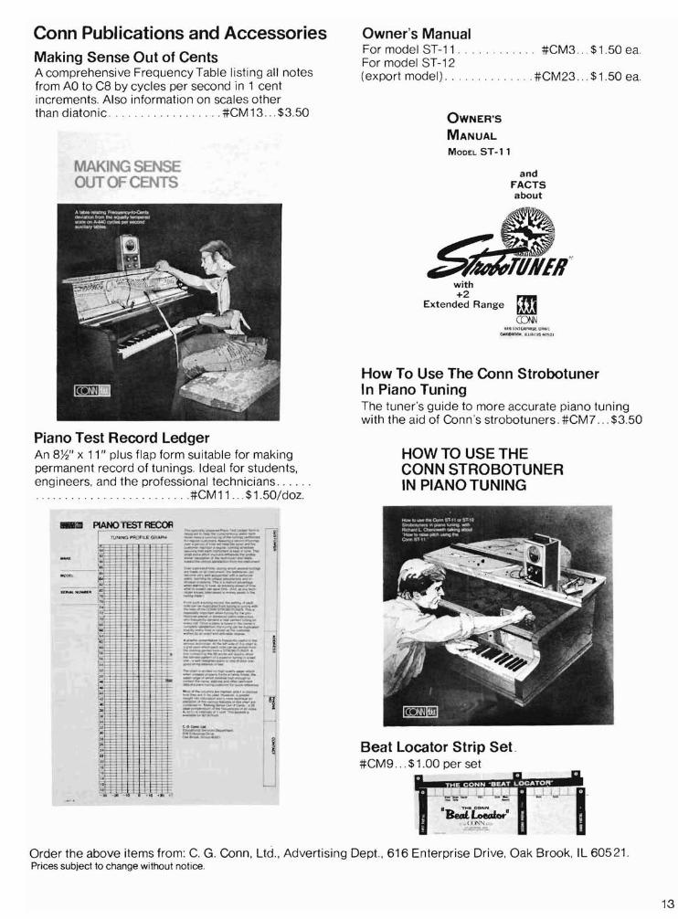
Conn Publications and Accessories Making Sense Out of Cents A comprehensive FrequencyTable listing all notes from AO to C8 by cycles per second in 1 cent increments. Also information on scales other than diatonic #CM13 $3.50
MAKING SENSE OUTOFCENTS
Piano Test Record Ledger An 8W' x 11" plus flap form suitable for making permanent record of tun ings. Ideal for students, engineers, and the professional technicians . . ... .. . . .. .. .. . . . . . . . .. . .#CM 11.. .$1.50/doz.
lIIlIlIil1I
Owner's Manual For model ST-11 . . #CM3 $1.50 ea. For model ST-12 (export model ) #CM23 $1.50 ea.
OWNER'S
MANUAL
MODEL ST-ll
and FACTS about
with +2
Extended Range
6 1G"'~ l l ,WIl I :tl UNl\ l
Q,to l<J!WW'Ilo l:, i l t ."~ N'~' 1
How To Use The Conn Strobotuner In Piano Tuning The tune r's guide to more accurate piano tuning with the aid of Conn 's strobotuners. #CM7 . .. $3.50
HOW TO USE THE CONN STROBOTUNER IN PIANO TUNING
Beat Locator Strip Set . #CM9 ... $1.00 per set
. .~_\,l~. I
.~.~. ( :( \'\::'\' , ,"
Order the above items from: C. G. Conn, l.td ., Advertising Dept., 616 Enterprise Drive, Oak Brook, IL 60521 . Prices subject to change without notice.
13