
The Refined Process Structure Tree
53
The Refined Process Structure Tree Jussi Vanhatalo * ,a,b , Hagen V ¨ olzer ** ,a , Jana Koehler a a IBM Zurich Research Laboratory, S¨ aumerstrasse 4, CH-8803 R¨ uschlikon, Switzerland b Institute of Architecture of Application Systems, University of Stuttgart, Universit¨ atsstrasse 38, D-70569 Stuttgart, Germany Abstract We consider a workflow graph as a model for the control flow of a business process and study the problem of workflow graph parsing, i.e., finding the structure of a workflow graph. More precisely, we want to find a decomposition of a workflow graph into a hierarchy of sub-workflows that are subgraphs with a single entry and a single exit of control. Such a decomposition is the crucial step, for example, to translate a process modeled in a graph-based language such as BPMN into a process modeled in a block-based language such as BPEL. For this and other applications, it is desirable that the decomposition be unique, modular and as fine as possible, where modular means that a local change of the workflow graph can only cause a local change of the decomposition. In this paper, we provide a decomposition that is unique, modular and finer than in previous work. We call it the refined process structure tree. It is based on and extends similar work for sequential programs by Tarjan and Valdes [ACM POPL ’80, 1980, pp. 95- 105.]. We give two independent characterizations of the refined process structure tree which we prove to be equivalent: (1) a simple descriptive characterization that justifies our particular choice of the decomposition and (2) a constructive characterization that allows us to compute the decomposition in linear time. The latter is based on the tree of triconnected components (elsewhere also known as the SPQR tree) of a biconnected graph. Key words: Work Flow Management, Workflow graph parsing, Model decomposition, Subprocess detection, Graph theory * Primary corresponding author: Tel.: +41 44 724 8111; fax: +41 44 724 8953. ** Corresponding author: Tel.: +41 44 724 8395; fax: +41 44 724 8953. Email addresses: [email protected] (Jussi Vanhatalo), [email protected] (Hagen V ¨ olzer), [email protected] (Jana Koehler) Preprint submitted to Data & Knowledge Engineering (DKE) January 16, 2009
Transcript of The Refined Process Structure Tree

The Refined Process Structure Tree
Jussi Vanhatalo∗,a,b, Hagen Volzer∗∗,a, Jana Koehlera
aIBM Zurich Research Laboratory, Saumerstrasse 4, CH-8803 Ruschlikon, SwitzerlandbInstitute of Architecture of Application Systems, University of Stuttgart, Universitatsstrasse 38,
D-70569 Stuttgart, Germany
Abstract
We consider a workflow graph as a model for the control flow of a business processand study the problem of workflow graph parsing, i.e., finding the structure of aworkflow graph. More precisely, we want to find a decomposition of a workflowgraph into a hierarchy of sub-workflows that are subgraphs with a single entryand a single exit of control. Such a decomposition is the crucial step, for example,to translate a process modeled in a graph-based language such as BPMN intoa process modeled in a block-based language such as BPEL. For this and otherapplications, it is desirable that the decomposition be unique, modular and asfine as possible, where modular means that a local change of the workflow graphcan only cause a local change of the decomposition. In this paper, we providea decomposition that is unique, modular and finer than in previous work. Wecall it the refined process structure tree. It is based on and extends similar workfor sequential programs by Tarjan and Valdes [ACM POPL ’80, 1980, pp. 95-105.]. We give two independent characterizations of the refined process structuretree which we prove to be equivalent: (1) a simple descriptive characterizationthat justifies our particular choice of the decomposition and (2) a constructivecharacterization that allows us to compute the decomposition in linear time. Thelatter is based on the tree of triconnected components (elsewhere also known asthe SPQR tree) of a biconnected graph.
Key words: Work Flow Management, Workflow graph parsing, Modeldecomposition, Subprocess detection, Graph theory
∗Primary corresponding author: Tel.: +41 44 724 8111; fax: +41 44 724 8953.∗∗Corresponding author: Tel.: +41 44 724 8395; fax: +41 44 724 8953.
Email addresses: [email protected] (Jussi Vanhatalo), [email protected](Hagen Volzer), [email protected] (Jana Koehler)
Preprint submitted to Data & Knowledge Engineering (DKE) January 16, 2009

1 INTRODUCTION 2
1. Introduction
The control flow of a business process can often be modeled as a workflowgraph [1]. Workflow graphs capture the core of many business process languagessuch as UML activity diagrams, BPMN and EPCs. We study the problem of pars-ing a workflow graph, that is, decomposing the workflow graph into a hierarchyof sub-workflows that have a single entry and a single exit of control, often alsocalled blocks, and labeling these blocks with a syntactical category they belongto. Such categories are sequence, if, repeat-until, etc., see Fig. 1(a). Such a de-composition is also called a parse of the workflow graph. It can also be shown asa parse tree, see Fig. 1(c).
s1 e1x2x1
a2a1
a4
s1 e1x4x3x2x1a1
a3a2s1 e1x4x3x2x1
a1a3a2
(a) (b)
If Repeat-UntilSequence 2
Sequence 1
If Repeat-UntilSequence 3
Sequence 1
(d)
If Sequence 3Sequence 1
(c) (e)
If
Repeat-Until
Sequence 1
Sequence 2
a1
a2 a3
If
Sequence 1
Sequence 3
a2 a4a1
Figure 1: (a), (b) Two parses of the same workflow graph. (c) Parse tree corresponding to (a). (d)Workflow graph obtained by a local change and its parse. (e) Parse tree corresponding to (d).
The parsing problem occurs when we want to translate a graph-based processdescription (e.g. a BPMN diagram) into a block-based process description (e.g.BPEL process), but there are also other use cases for workflow graph parsing.For example, Vanhatalo, Volzer and Leymann [2] show how parsing speeds upcontrol-flow analysis. Kuster et al. [3] show how differences between two processmodels can be detected and resolved based on decompositions of these processmodels. Gschwind et al. [4] use parsing for pattern-based editing operations ofprocess models. We believe that parsing also helps in understanding large pro-cesses and in finding reusable subprocesses.
For a roundtripping between a BPMN diagram and a BPEL process, it is de-sirable that the decomposition be unique, i.e., the same BPMN diagram always

1 INTRODUCTION 3
translates to the same BPEL process. Consider, for example, the workflow graphin Fig. 1(a). The translation algorithm proposed by Ouyang et al. [5] is non-deterministic. It may produce one of the two parses shown in Fig. 1(a) and (b),depending on whether the if-block or the repeat-until-block is found first by theparsing algorithm.
One idea to resolve some of this nondeterminism is to define priorities onthe syntactic categories to be found [5, 6, 7]. For example, if in each step theparsing algorithm tries to find sequences first, then if-blocks and then repeat-until-blocks, we can only obtain the parse in Fig. 1(a) in our example. However, thiscan introduce another problem. If we change a single block, say, the repeat-untilblock by replacing it, e.g. by a single task, we obtain the workflow graph shownin Fig. 1(d). Fig. 1(d) also shows the parse we obtain with the particular prioritiesmentioned above. The corresponding parse tree is shown in Fig. 1(e). It cannotbe derived from the tree in Fig. 1(c) by just a local change, viz., by replacingthe Repeat-Until subtree. For a roundtripping between a BPMN diagram and aBPEL process, it would be much more desirable that a local change in the BPMNdiagram also result in only a local change in the BPEL process. Replacing a blockin the BPMN diagram would therefore only require replacing the correspondingblock in the BPEL process. We then call a such decomposition modular. Theexisting approach to the BPMN to BPEL translation problem [5] is not modular.Furthermore, it does not provide, because of the above problems, a specificationof the translation that is independent of the actual translation algorithm.
A unique and modular decomposition is provided by the program structuretree defined by Johnson et al. [8, 9] for sequential programs. It was applied toworkflow graphs by Vanhatalo et al. [2] to find control-flow errors. The corre-sponding decomposition for our first example is shown in Fig. 2. It uses the samenotion of a block as Ouyang et al. [5] do, that is, a block is a connected sub-graph with a single entry and a single exit edge. But in contrast to the approach ofOuyang et al. [5], non-maximal sequences are disregarded in the program struc-ture tree. For example, Sequence 2 in Fig. 1(a) [likewise Sequence 3 in subfigure(b)] is non-maximal: it is in sequence with another block.
Another general requirement for parsing is to find as much structure as possi-ble, i.e., to decompose into blocks that are as fine as possible. As we will see (cf.Sect. 6), this allows us to map more BPMN diagrams to BPEL in a structured way.It has also been argued [5] that the BPEL process is more readable if it containsmore blocks. Furthermore, debugging is easier when an error is local to a smallblock rather than to a large one.
In this paper, we provide a new decomposition that is finer than the program

1 INTRODUCTION 4
Sequence 1If Repeat-Until
s1 e1x4x3x2x1a1
a3a2
Figure 2: Modular decomposition of the process from Fig. 1.
structure tree as defined by Johnson et al. [8, 9]. It is based on and extends similarwork for sequential programs by Tarjan and Valdes [10]. The underlying notionof a block is a connected subgraph with unique entry and exit nodes (as opposedto edges in the previous approach). Accordingly, all blocks of the previous ap-proach are found, but more may be found, resulting in a more refined parse tree.Therefore, we call our decomposition the refined process structure tree (RPST, forshort). We prove that our RPST is unique and modular.
Our parsing technique is not restricted to workflow graphs. It can be appliedto any two-terminal graph (defined in Sect. 2.1). It can therefore be applied toWorkflow (Petri) Nets, YAWL, flow charts, control-flow graphs of programs, andsimilar directed graph representations.
Some of these results have been presented earlier in a conference paper [11].In this version, we extend the previous publication by presenting proofs of ourpropositions and theorems, and by providing a new, simple independent charac-terization of the RPST, which gives an additional justification of our particularchoice of the decomposition showing that the RPST is optimal in the followingsense. We cannot obtain any finer decomposition than the RPST that is basedon the same definition of fragment, unless we are willing to make some choicebetween fragments that cannot be included in a same parse tree. Later we arguethat such a choice would be somewhat arbitrary, not dependent on the structuralinformation we would like to detect.
We prove that this new characterization is equivalent with our previous con-structive characterization [11], which serves as a basis for computing the decom-position in linear time. The computation is based on the triconnected componentsof a biconnected graph, which can also be computed in linear time, for exampleby using an algorithm by Hopcroft and Tarjan [12].
The paper is structured as follows. In Sect. 2, we define the RPST throughour simple independent characterization. In Sect. 3, we present our constructivecharacterization for the RPST. In Sect. 4, we prove some properties of the RPSTincluding its modularity. In Sect. 5, we describe how to compute the RPST in

2 THE REFINED PROCESS STRUCTURE TREE 5
linear time. Proofs can be found in the appendix.
2. The Refined Process Structure Tree
First we review the notion of a fragment from existing literature in Sect. 2.1.In Sect. 2.2, we define the RPST based on our particular selection of fragmentsthat we call the objective fragments.
2.1. FragmentsWe start by recalling some basic notions of graph theory. A multi-graph is a
graph in which two nodes may be connected by more than one edge. This canbe formalized as a triple G = (V, E, M), where V is the set of nodes, E the setof edges and M a mapping that assigns an ordered or unordered pair of nodes toeach edge—for a directed or undirected multi-graph, respectively. We will usemulti-graphs throughout the paper, directed and undirected, but we will call themgraphs for simplicity.
Let G be a graph. If e is an edge of G that connects two nodes u and v, we alsosay that u and v are incident to e, e is incident to u and v, and nodes u and v areadjacent.
Workflow graphs are based on two-terminal graphs1. A two-terminal graph(TTG for short) is a directed graph G without self-loops such that there is a uniquesource node s and a unique sink node t , s and each node v is on a directedpath from s to t. The undirected version of G, denoted U(G), is the undirectedgraph that results from ignoring the direction of all the edges of G and adding anadditional edge between the source and the sink. The additional edge is called thereturn edge of U(G). Figure 3 shows examples of (a) a two-terminal graph G, and(b) its undirected version U(G), where r is the return edge.
For a subset F of edges, let VF denote the set of nodes that are incident tosome edge in F and let GF denote the subgraph with nodes VF and edges F. Wesay that GF is formed by F.
Definition 1 (Boundary node, entry, exit, fragment). Let G be a TTG and F asubset of its edges such that GF is a connected subgraph of G.
1. A node v ∈ VF is a boundary node of F if it is the source or sink node of G,or if G has edges e ∈ F and e′ < F such that v is incident to e and e′.
1A workflow graph is a two-terminal graph in which each node is labeled with some controlflow logic such as AND, OR, etc.

2 THE REFINED PROCESS STRUCTURE TREE 6
s
v2
v1
v3 v4 v7v5 v6 t
a
b
c
d j
n
ef
g
h
i
k l
m
o
(a) (b)
G U(G) r
s
v2
v1
v3 v4 v7v5 v6 t
a
b
c
d j
n
ef
g
h
i
k l
m
o
Figure 3: (a) Two-terminal graph G, and (b) its undirected version U(G), where r is the returnedge.
2. A boundary node v is an entry of F if no incoming edge of v is in F or if alloutgoing edges of v are in F.
3. A boundary node v is an exit of F if all incoming edges of v are in F or ifno outgoing edge of v is in F.
4. F is called a fragment of G if it has exactly two boundary nodes, an entryand an exit. Let F (u, v) denote the set of all fragments with entry u and exitv.
A fragment F is trivial if F contains exactly one edge e. If a fragment is nottrivial, we call it non-trivial. As a TTG contains no self-loops, any set F of edgescontaining only one edge is a fragment.
(a) (b) (c)
d
a
cu v
wb
F3
a
cu v
wb
F1 d
a
cu v
wb
F2
Figure 4: (a), (b) Examples and (c) counterexamples of entry, exit and fragment.
Figure 4 shows examples of fragments. A fragment is indicated as a dottedbox. It contains all those edges that either are inside the box or cross the boundaryof the box. Thus, the box in subfigure (a) denotes the fragment F1 = {a, b, c}.Node u is the entry and node v is the exit of F1. In subfigure (b), F2 = {a, b, c, d}is a fragment with entry u and exit v. In subfigure (c), F3 = {a, b, c, d} has twoboundary nodes, u and v, neither of them is an entry or an exit of F3. Therefore,F3 is not a fragment.
Note that it can be checked locally whether a boundary node is an entry oran exit. This notion of fragment was proposed by Tarjan and Valdes [10], where

2 THE REFINED PROCESS STRUCTURE TREE 7
a TTG modeled the control flow of a sequential program. When control flowsthrough any of the edges of a fragment, then it must have flown through the entrybefore and must flow through the exit after. Their notion of fragment is, in a sense,the most general notion of fragment having this property that can still be verifiedlocally [10].
2.2. Objective Fragments and the Refined Process Structure TreeWe want to find a decomposition of a workflow graph into fragments. For-
mally such a decomposition (or a parse) of a TTG G = (V, E, M) is a hierarchyof fragments, i.e., a set E of fragments such that E ∈ E, and no two fragments inE overlap.2 A trivial example of such a decomposition is the set {E}. A decom-position E is maximal if there exists no fragment F such that E ∪ {F} is also adecomposition.
ts u vb ca
(a)
N1
P
ts u vb ca
(b)
N2
P
ts u vb ca
(c)
P
Figure 5: (a), (b) Two maximal decompositions, (c) a non-maximal decomposition.
(a)
u v
a
c
b
N1B
(b)
u v
a
c
b
N2
B
(c)
u v
a
c
b
B
Figure 6: (a), (b) Two maximal decompositions, (c) a non-maximal decomposition.
Figure 5 shows a TTG and (a)-(b) its two maximal decompositions and (c) anon-maximal decomposition. Figure 6 shows another such example. In case two
2Where we say that two fragments F1 and F2 overlap if F1∩F2 , ∅, F1\F2 , ∅ and F2\F1 , ∅.Therefore, if two fragments F1 and F2 do not overlap, they are either nested (F1 ⊆ F2, or F2 ⊆ F1)or disjoint (F1 ∩ F2 = ∅).

2 THE REFINED PROCESS STRUCTURE TREE 8
fragments overlap as N1 and N2 do in Figs. 5 and 6, no decomposition containsboth of them. Therefore, in order to obtain a unique decomposition, we mustdecide to exclude either one of them or both from the decomposition. As thereis no reasonable argument to favor N1 over N2, or vice versa, that would breakthe symmetry between them, we exclude both fragments. Hence, we obtain thenon-maximal decomposition shown in Figs. 5(c) and 6(c) respectively. These de-compositions are obtained in general by excluding all those fragments that overlapwith some fragment. A fragment that does not overlap with any other fragmentis contained in each maximal decomposition. Hence we call it objective frag-ment. The set of objective fragments is clearly a decomposition which is uniquelydetermined. This is how we define the refined process structure tree.
Definition 2 (Refined process structure tree (RPST)). Let G = (V, E, M) be aTTG.
1. A fragment of G is objective if it does not overlap with any other fragmentof G.
2. The set of all objective fragments of G is called the RPST decomposition ofG.
3. The corresponding parse tree is called the refined process structure tree(RPST) of G, i.e. the RPST is the tree of the objective fragments suchthat the parent tree node of an objective fragment F is the smallest objectivefragment that properly contains F.
If a fragment is not objective, we call it non-objective. Fragments N1 andN2 in Figs. 5 and 6 are examples of non-objective fragments. Each non-objectivefragment occurs in some maximal decomposition, but not in all.
s
v2
v1
v3 v4 v7v5 v6 t
a
b
c
d j
n
ef
g
h
i
k l
m
o
(b)(a)
P1T1 B1
S1
G P1
T1 B1
S1
j k lm
c d f gea b h i n
o
Figure 7: (a) The objective fragments of G, and (b) the refined process structure tree of G.
Figure 7 shows (a) a TTG G and its objective fragments, and (b) its RPST. Theroot of the RPST is the largest fragment that contains all the edges of G, and has

3 AN EQUIVALENT CHARACTERIZATION OF THE RPST 9
the source and the sink as the boundary nodes. If a fragment F is the parent treenode (parent, for short) of a fragment F′ in the RPST, we say F′ is a child of F.
Note that each trivial fragment is also an objective fragment. As there is a one-to-one correspondence between edges and trivial fragments, we represent eachtrivial fragment by the respective edge in the RPST. Note that each trivial fragmentis a leaf node of the RPST, whereas each non-trivial fragment is a non-leaf node.
3. An Equivalent Characterization of the RPST
The definition of the RPST is quite simple but it does not give us a methodto compute the RPST efficiently. For this purpose, we give an equivalent charac-terization of objective fragments (and hence the RPST) in this section, which willallow us to provide a linear-time algorithm to compute the RPST. We also use thischaracterization in Sect. 4 to show how the RPST represents not only the objectivefragments but also all the non-objective fragments, and to prove that the RPST ismodular.
This characterization is based on the relationship of fragments and tricon-nected components that we prove in Sect. 3.1. In Sect. 3.2, we define varioustypes of fragments including bond fragments on which we base our constructivecharacterization of objective fragments in Sect. 3.3.
3.1. Triconnected ComponentsTarjan and Valdes [10] have shown that the fragments of a TTG are closely
related to the triconnected components of its undirected version. We have to in-troduce a few more notions from graph theory.
Let G be an undirected graph. The following notions are also used for directedgraphs by ignoring the direction of their edges. Let W be a subset of nodes of G.A path from v0 to vk is an alternating sequence π = v0, e1, v1, e2, ..., vk of nodes andedges of G, such that ei is incident to vi−1 and vi for every i = 1, ..., k. Two nodesu, v < W are connected without W if there is a path that contains u and v but nonode w ∈ W. For instance, in Fig. 3(a) nodes s and t are connected without v6, butnot connected without v5. Two edges e, f are connected without W if there existsa path containing e and f in which a node w ∈ W may only occur as the first or lastelement. A graph without self-loops is k-connected, k > 0, if it has at least k + 1nodes and for every set W of k − 1 nodes, any two nodes u, v < W are connectedwithout W. We say connected for 1-connected, biconnected for 2-connected andtriconnected for 3-connected. A separation point (separation pair) of G is a nodeu (pair {u, v} of nodes) such that there exists two nodes that are not connected

3 AN EQUIVALENT CHARACTERIZATION OF THE RPST 10
without {u} (without {u, v}). Therefore a graph is biconnected (triconnected) ifand only if it has no separation point (separation pair). For instance in Fig. 3, G isnot biconnected, because v5 is a separation point, whereas U(G) is biconnected,because it has no separation points. U(G) is not triconnected, because {v5, v7} isa separation pair. In Fig. 8(a), T2 is an example of a triconnected graph if thedashed edge x is considered as an ordinary edge.
We say that a graph is weakly biconnected if it is biconnected or if it containsexactly two nodes and at least two edges between these two nodes. For instance,in Fig. 8(a), B1 is weakly biconnected, but not biconnected.
Throughout the paper, we assume that U(G) is weakly biconnected. This caneasily be achieved by splitting each separation point into two nodes, where theonly outgoing edge of the first node is the only incoming edge of the second node.3
Let {u, v} be a pair of nodes. A separation class with respect to (w.r.t.) {u, v}is a maximal set S of edges such that any pair of edges in S is connected without{u, v}; S is a proper separation class or branch if it does not contain the returnedge; {u, v} is called a boundary pair if there are at least two separation classesw.r.t. {u, v}. Note that a pair {u, v} of nodes is a boundary pair if and only if it is aseparation pair or u and v are adjacent in G. For instance in Fig. 3(b), {v5, v7} and{v6, v7} are boundary pairs. The pair {v5, v7} is also a separation pair, but {v6, v7}is not.
Each weakly biconnected graph can be uniquely decomposed into a set ofgraphs, called its triconnected components [12], where each triconnected compo-nent is either a bond, a polygon or a triconnected graph. A bond is a graph thatcontains exactly two nodes and at least two edges between them. A polygon is agraph that contains at least three nodes, exactly as many edges as nodes such thatthere is a cycle that contains all its nodes and all its edges.
Part (a) in Fig. 8 shows the six triconnected components of graph U(G) fromFig. 3. P1 and P2 are polygons, B1 and B2 are bonds, and T1 and T2 are tricon-nected graphs. Each component contains virtual edges (shown as dashed lines),which are not contained in the original graph. They contain the information onhow the components are related to each other: Each virtual edge occurs in exactlytwo components, whereas each original edge occurs in exactly one component.For example, the virtual edge x occurs in components T1 and T2. In component
3It is often assumed for workflow graphs that no node has both multiple incoming and multipleoutgoing edges. In that case it follows that U(G) is biconnected. See also Sect. 6.

3 AN EQUIVALENT CHARACTERIZATION OF THE RPST 11
j k
s
v2
v1
v3 v4 v7v5 v6 t
a
b
c
d j
n
ef
g
h
i
k l
m
o
s v5 v7 tu w
r
o
s
v2
v1
v5
a
b
h
i
u
x
v2
v1
v3 v4
c
d
ef
gx
v5 v7
n
m
w
y
v5 v6j
k
z
v5 v6 v7l
y
z
(a) (c)
P1T1
T2
B2
B1
P2
P1
T1
P2T2
B2
B1
(b)
P2T2
T1 B1
B2
P1
G
a b h i m n
l
o
c d f ge
u w
y
z
x
Figure 8: (a) The triconnected components of U(G) in Fig. 3, (b) the tree of the triconnectedcomponents of U(G), and (c) the corresponding component subgraphs of G.
T1, x represents the component T2, whereas x represents T1 in T2. Therefore, weobtain the original graph by merging the triconnected components at the virtualedges (which removes them).
The triconnected components can be arranged in a tree, cf. Fig. 8(b), wheretwo components are connected if they share a virtual edge. The root of the treeis the unique component that contains the return edge. Each original edge is alsoshown in the tree under the unique component that contains that edge. Therefore,each component C determines a set F of edges of the original graph, namely all theleafs of the subtree that C corresponds to. For example, component T1 determinesthe set F = {a, b, c, d, e, f , g, h, i} of edges. We call the subgraph formed by sucha set F of edges the component subgraph of C. Figure 8(c) shows the componentsubgraphs of G. Note that the component subgraphs B1, P1 and T1 are fragments,whereas B2, P2 and T2 are not. There are also fragments that are not componentsubgraphs, for instance, { j, k, l,m}.
The precise definition of the triconnected components [13, 14, 12] is ratherlengthy and is therefore presented in App. A.1. Instead we present here the exactrelationship between the triconnected components and fragments we are goingto exploit. The proofs of the following two theorems are presented in App. A.2.First, we observe that triconnected components are closely related to boundary

3 AN EQUIVALENT CHARACTERIZATION OF THE RPST 12
pairs.
Theorem 1. A set {u, v} of two nodes is a boundary pair of U(G) if and only if
1. nodes u and v are adjacent in U(G),2. a triconnected component of U(G) contains a virtual edge between u and v,
or3. a triconnected component of U(G) is a polygon and contains u and v.
Proof. Presented in App. A.2. �
We show examples based on U(G) in Fig. 3(b) and its triconnected compo-nents in Fig. 8(a). For instance, the boundary pair {v6, v7} contains two adjacentnodes of U(G), the boundary pair {v1, v2} corresponds to a virtual edge x of T2,and the boundary pair {s, v7} contains two nodes of the polygon P1. Boundarypairs are closely related to fragments as follows.
Theorem 2. 1. If F ∈ F (u, v), then {u, v} is a boundary pair of U(G) and F isthe union of one or more proper separation classes w.r.t. {u, v}.
2. Let {u, v} be a boundary pair of U(G) and F the union of one or more properseparation classes w.r.t. {u, v}. If u is an entry of F and v is an exit of F,then F ∈ F (u, v).
Proof. Presented in App. A.2. �
For instance, the boundary pair {v5, v7} has three proper separation classes{m}, P2 = { j, k, l}, and {n}. P2 is not a fragment, because v5 is neither its entry norits exit, whereas {m} ∈ F (v5, v7) and {n} ∈ F (v7, v5) are fragments. The unionof P2 and {m} is a fragment, whereas P2∪{n} and {m}∪ {n} are not. P2∪{m}∪ {n}is a fragment.
Theorem 1 says that the boundary pairs can be obtained from the triconnectedcomponents while Thm. 2 says that the fragments can be obtained from the bound-ary pairs.
3.2. Sequences and Bond FragmentsWe define various types of fragments on which we base our constructive char-
acterization of the objective fragments in Sect. 3.3.Figure 9 shows examples of fragments N1 and N2 that each overlap with some
other fragment. As we discussed in Sect. 2.2, we exclude sequences N1 and N2in Fig. 9(a) from the RPST, as they overlap. We can distinguish these overlappingsequences from the other sequences, such as P in Fig. 5, based on the followingdefinition.

3 AN EQUIVALENT CHARACTERIZATION OF THE RPST 13
(b)
u v
a
c
b
(c)
a
d
bu vc
N2
N1
N2
N1
ts u vb ca
(a)
N1N2
Figure 9: Examples of overlapping fragments.
Definition 3 (Maximal sequence). 1. If F0 ∈ F (v0, v1) and F1 ∈ F (v1, v2)such that F0 ∪ F1 = F ∈ F (v0, v2), we say that F0 and F1 are in sequence(likewise: F1 and F0 are in sequence) and that F is a sequence.
2. F is a maximal sequence if there is no fragment F2 such that F and F2 arein sequence.
If a sequence is not maximal, we call it non-maximal. In Fig. 5, N1 and N2 arenon-maximal sequences, whereas {a, b, c} is a maximal sequence. We observe thateach non-maximal sequence overlaps with some other non-maximal sequence,and is therefore non-objective. We also note that each maximal sequence does notoverlap with any other sequence. The proofs for these observations are includedin the proof of Thm. 7 presented in Sect. 3.3.
Figures 9(b)-(c) show examples of non-objective fragments N1 and N2, forwhich it is less straightforward to distinguish them from the objective fragmentsthan for the non-maximal sequences. In order to distinguish these non-objectivefragments from the objective ones, we first define various types of bond fragmentsas follows.
Definition 4 (Bond fragments). Let S be a proper separation class (i.e., a branch)w.r.t. {u, v}. S is directed from u to v if it contains neither an incoming edge of unor an outgoing edge of v. D(u, v) denotes the set of directed branches from u tov. S is undirected if it is neither in D(u, v) nor in D(v, u). The set of undirectedbranches between u and v is denoted by U (u, v). A fragment X ∈ F (u, v) is
1. a bond fragment if it is the union of at least two branches from D(u, v) ∪U (u, v) ∪D(v, u).
2. a directed bond fragment if it is the union of at least two branches fromD(u, v) ∪U (u, v).
3. a semi-pure bond fragment if it is the union of at least two branches fromD(u, v) ∪U (u, v), and
3 AN EQUIVALENT CHARACTERIZATION OF THE RPST 14
(a) there exists no Y ∈ U (u, v) such that Y ⊆ X, Y has an edge incomingto u, or
(b) there exists no Y ∈ U (u, v) such that Y ⊆ X, Y has an edge outgoingfrom v.
4. a pure bond fragment if it is the union of at least two branches from D(u, v).
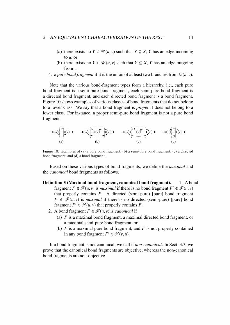
Note that the various bond-fragment types form a hierarchy, i.e., each purebond fragment is a semi-pure bond fragment, each semi-pure bond fragment isa directed bond fragment, and each directed bond fragment is a bond fragment.Figure 10 shows examples of various classes of bond fragments that do not belongto a lower class. We say that a bond fragment is proper if does not belong to alower class. For instance, a proper semi-pure bond fragment is not a pure bondfragment.
(a) (b) (c) (d)
vu w vu w vu vuR S D
B
Figure 10: Examples of (a) a pure bond fragment, (b) a semi-pure bond fragment, (c) a directedbond fragment, and (d) a bond fragment.
Based on these various types of bond fragments, we define the maximal andthe canonical bond fragments as follows.
Definition 5 (Maximal bond fragment, canonical bond fragment). 1. A bondfragment F ∈ F (u, v) is maximal if there is no bond fragment F′ ∈ F (u, v)that properly contains F. A directed (semi-pure) [pure] bond fragmentF ∈ F (u, v) is maximal if there is no directed (semi-pure) [pure] bondfragment F′ ∈ F (u, v) that properly contains F.
2. A bond fragment F ∈ F (u, v) is canonical if(a) F is a maximal bond fragment, a maximal directed bond fragment, or
a maximal semi-pure bond fragment, or(b) F is a maximal pure bond fragment, and F is not properly contained
in any bond fragment F′ ∈ F (v, u).
If a bond fragment is not canonical, we call it non-canonical. In Sect. 3.3, weprove that the canonical bond fragments are objective, whereas the non-canonicalbond fragments are non-objective.

3 AN EQUIVALENT CHARACTERIZATION OF THE RPST 15
In the following, we prepare for this by studying how the bond fragments thatshare a common boundary pair are related to each other. Bond fragments areclosed under composition.
Proposition 3. If X,Y ∈ F (u, v) and F = X ∪ Y, then F ∈ F (u, v). If X andY are bond fragments, so is F. If X and Y are directed (semi-pure) [pure] bondfragments, so is F.
Proof. Presented in App. A.3. �
Proposition 3 assures that a maximal bond fragment, maximal directed, maxi-mal semi-pure, or maximal pure bond fragment is unique if it exists.
In the rest of this section, we show that any two bond fragments that sharea common boundary pair do not overlap if at least one of them is canonical. Ingeneral, we can encounter two situations depending on whether the union of allbranches between two boundary nodes is a fragment or not. Examples of thesetwo cases are shown in Fig. 11.
(a) (b)
v3
v4v1
v2
v3
v4v1
v2
B
R
S
DR2
R1
S
Figure 11: Examples of various classes of maximal bond fragments.
In Fig. 11(a), the union of all the branches between the boundary nodes u andv is a fragment B, because u is an entry and v is an exit. As B contains all thebranches between u and v, B is the maximal bond fragment from u to v. D is themaximal directed bond fragment from u to v. S is the maximal semi-pure bondfragment from u to v. R is the maximal pure bond fragment from u to v.
Compared to part (a) of Fig. 11, part (b) has an additional edge outgoing fromu that is outside of the union A of all the branches between the boundary nodes uand v. Because of this added edge, neither u nor v is an entry of A. Thus, A is nota fragment. R1 is the maximal pure bond fragment from u to v. S is the maximalsemi-pure bond fragment from u to v. As there is no larger bond fragment from uto v, S is also the maximal directed and maximal bond fragment from u to v. R2 is
3 AN EQUIVALENT CHARACTERIZATION OF THE RPST 16
the maximal pure bond fragment from v to u. As there is no larger bond fragmentfrom v to u, R2 is also the maximal semi-pure, maximal directed, and maximalbond fragment from v to u.
Next, we observe that a proper semi-pure bond fragment and a proper directedbond fragment are unique with respect to their boundary pairs if they exist.
Proposition 4. Let G be a TTG such that its completed version is weakly bicon-nected.
1. If F, F′ ∈ F (u, v) are proper semi-pure bond fragments of G, then F = F′.2. If F, F′ ∈ F (u, v) are proper directed bond fragments of G, then F = F′.
Proof. Presented in App. A.3. �
We can show now that a canonical bond fragment does not overlap with anyother (canonical or non-canonical) bond fragment that shares the same boundarynodes.
Proposition 5. Let G be a TTG such that its completed version is weakly bicon-nected.
1. Let X,Y ∈ F (u, v) be bond fragments of G, and X be canonical. ThenX ⊆ Y, or Y ⊆ X.
2. Let X ∈ F (u, v) and Y ∈ F (v, u) be bond fragments of G, and X or Y becanonical. Then X ⊆ Y, Y ⊆ X, or X ∩ Y = ∅.
Proof. Presented in App. A.3. �
3.3. The Constructive Characterization: The Canonical FragmentsWe give a constructive characterization of the objective fragments. For this,
we define the canonical fragments, and prove that the objective fragments and thecanonical fragments coincide.
Definition 6 (Canonical fragment). A fragment is canonical if it is a maximalsequence, a canonical bond fragment, or neither a sequence nor a bond fragment.
If a fragment is not canonical, we call it non-canonical. Note that each trivialfragment is canonical. Part (a) of Fig. 7 shows the non-trivial canonical fragmentsof graph G. P1 is a maximal sequence. S 1 ∈ F (v5, v7) is a maximal semi-purebond fragment, and B1 ∈ F (v5, v7) is a maximal bond fragment. T1 is neither asequence nor a bond fragment.

4 PROPERTIES OF THE RPST 17
In order to prove that the canonical fragments are exactly the objective frag-ments, we also give a constructive characterization of the non-canonical frag-ments.
Proposition 6. Let G be a TTG, F ∈ F (u, v) be a fragment of G. F is a non-canonical fragment if and only if either
1. F is a non-maximal sequence,2. F is a non-maximal pure bond fragment3. F is a non-maximal proper bond fragment, or4. F is a maximal pure bond fragment and F is properly contained in a bond
fragment F′ ∈ F (v, u).
Proof. Presented in App. A.3. �
For example, the fragments N1 and N2 in Fig. 9(a) are non-maximal se-quences. The fragments N1 and N2 in Fig. 9(b) are non-maximal pure bondfragments. The fragments N1 and N2 in Fig. 9(c) are non-maximal proper bondfragments. The fragment {a, d} in Fig. 9(c) is a maximal pure bond fragment thatis properly contained in a bond fragment {a, b, c, d}.
Finally, we show that the objective fragments and canonical fragments coin-cide.
Theorem 7. Let F be a fragment of a TTG. F is canonical if and only if F isobjective.
Proof. Presented in App. A.3. �
4. Properties of the RPST
In this section, we give two additional justifications for our definition of theRPST. First, we show in Sect. 4.1 how all fragments can be easily derived fromthe canonical fragments, for instance, as a combination of child fragments in theRPST. Secondly, we prove in Sect. 4.2 that the RPST is modular.
4.1. Computing all Fragments from the Canonical FragmentsThe following proposition indicates how to derive all fragments (also the non-
canonical) from the canonical fragments. This is useful for example if one wantsto find the smallest fragment that contains some given set of graph elements.

4 PROPERTIES OF THE RPST 18
Proposition 8. Let F be a set of edges in a TTG. F is a fragment if and only if Fis a canonical fragment or F is
1. a union of consecutive child fragments of a maximal sequence,2. a union of child fragments of a maximal pure bond fragment, or3. a union of child fragments of a maximal bond fragment B such that B is not
a maximal directed bond fragment.
Proof. Presented in App. A.4. �
To define consecutive child fragments of a sequence, the child fragments of asequence are ordered left to right from the entry to the exit of the sequence. Forexample, the maximal sequence P1 in Fig. 7 has T1, B1 and o as ordered childfragments. Besides these canonical fragments and the maximal sequence, also theunion of T1 and B1 (B1 and o) is a fragment. However, the union of T1 and ois not a fragment, as these are not consecutive child fragments, i.e., they do notshare a boundary node.
(a)
u v
Ra
c
b
(b)
Bc
b
d
u va R
Figure 12: Deriving non-canonical fragmentsfrom child fragments of (a) a maximal pure bondfragment and (b) a maximal bond fragment.
Part (a) of Fig. 12 shows a maxi-mal pure bond fragment R = {a, b, c}.Its child fragments are {a}, {b}, and{c}. It follows from Prop. 8 that {a, b},{b, c}, and {a, c} are the non-canonicalfragments in R. Part (b) of Fig. 12shows a maximal bond fragment B =
{a, b, c, d} ∈ F (u, v) and a maximaldirected bond fragment R = {a, b} ∈F (u, v) such that B , R. It followsfrom Prop. 8 that {c, d}, {a, b, c} and{a, b, d} are the non-canonical fragments in B. Note that {a, c, d} and {b, c, d} arenot fragments, because their boundary nodes are neither entries nor exits.
4.2. ModularityFinally, we state what we mean by saying that our decomposition is modular.
Theorem 9. Let G be a TTG and X ∈ F (u, v) be a canonical fragment of G. LetG′ be the TTG obtained by replacing the subgraph that is formed by X by someother subgraph formed by a set of (fresh) edges X′ such that X′ ∈ F (u, v) is againa fragment of G′ (but not necessarily canonical) with the same entry-exit pair asX. Assume that A is the parent fragment of X in G and F , X is a child fragment

5 COMPUTING THE RPST 19
of A in G. Let A′ = (A \ X) ∪ X′ and F′ = F. Then A′ and F′ are canonicalfragments of G′ where F′ is a child fragment of A′ in G′.
Proof. Presented in App. A.4. �
Theorem 9 means that a local change to the TTG, i.e., changing a canonicalfragment X, only affects the RPST locally. The parent and siblings of a changedcanonical fragment remain in the RPST in the same place and it follows induc-tively that this is also true for all canonical fragments above the parent and allcanonical fragments below the siblings of X.
5. Computing the RPST
In this section, we describe an algorithm that computes the RPST in lineartime. We have extended the algorithm by Valdes [15] to find all the canonicalfragments (his algorithm produces a coarser decomposition, cf. Sect. 6). The al-gorithm has three high-level steps, which are illustrated in Fig. 13 and describedin Alg. 1. In Step 1, the tree of the triconnected components is computed, us-ing e.g. the linear-time algorithm by Hopcroft and Tarjan [12]. Gutwenger andMutzel [14] present some corrections to this algorithm. We illustrate the com-puted triconnected components through the respective component subgraphs inFig. 13.
In Step 2, we analyze each triconnected component to determine whether therespective component subgraph is a fragment. This can be done in linear time withthe following approach that takes advantage of the hierarchy of fragments. Weanalyze the tree of the triconnected components bottom-up—all children before aparent. For each child edge of a triconnected component c, we check whether it isincoming to or outgoing from one of the two boundary nodes of c. We count theseedges to determine whether a boundary node is an entry, an exit, or neither. Basedon this information, we can determine whether the respective component subgraphis a fragment. Note that when a triconnected component shares a boundary nodewith its parent, the same edges do not have to be counted twice, because an edgeinside a child is also inside its parent. We find some canonical fragments inStep 2, but not all. For example, in Fig. 13, the fragments P1, T1, and B1 arefound in Step 2, whereas the fragment S 1 is not.
In Step 3, we create the missing canonical fragments, and merge each com-ponent subgraph that is not a fragment to the smallest canonical fragment thatcontains it. This restructuring is based on the information computed in Step 2.

5 COMPUTING THE RPST 20
Algorithm 1 Computes the RPST for a two-terminal graph.buildRPST(Graph G)Require: G is a weakly biconnected TTG.{Step 1. Compute the tree of the triconnected components of the TTG.}Tree := Compute the tree of the triconnected components of G.{Step 2. Analyze each component to determine whether it is a fragment.}for each Component c in Tree in a post-order of a depth-first traversal do
Count the number of edges (that are children of c) incoming to/outgoing fromeach boundary node. (4 counts)Add these edge counts to the respective edge counts of the parent componentfor each shared boundary node.Compare these edge counts to the total number of incoming/outgoing edgesto determine whether each boundary node is entry, exit, or neither.Based on these boundary node types, determine whether c is a fragment.if c is a polygon then
Count the number of entry and exit nodes of the child components.If a child component is a fragment, order the child components from entryto exit.
{Step 3. Restructure the tree of the triconnected components into the tree of thecanonical fragments (the RPST).}for each Component c in Tree in a post-order of a depth-first traversal do
if c is a polygon thenMerge consecutive child components (that are not fragments if any exist)if those form a minimal child fragment.if c is not a fragment and c has at least two child fragments then
Create a maximal sequence (that contains a proper subset of children ofc).
if c is a bond thenClassify each branch of c based on the edge counts of the boundary nodesof the respective child components of c.if c is a fragment then
Based on the classifications of the branches, create the maximal pure,the maximal semi-pure, and the maximal directed bond fragment, if anyexists.
elseBased on the classifications of the branches, create the maximal purebond fragments, the maximal semi-pure bond fragment, if any exists.
for each Component d that has been created in this iteration doMerge the child fragments of each component in the to-be-merged-list ofd to d.
if c is not a fragment thenAdd c to the to-be-merged list (a linked list) of its parent component.Concatenate the to-be-merged list of c to the to-be-merged list of its parent.
elseMerge the child fragments of each component in the to-be-merged list ofc to c.
return Tree

5 COMPUTING THE RPST 21
G P1T1
T2
B2
B1
P2s
v2
v1
v3 v4 v7v5 v6 t
a
b
c
d j
n
ef
g
h
i
k l
m
o
G P1T1 B1
S1s
v2
v1
v3 v4 v7v5 v6 t
a
b
c
d j
n
ef
g
h
i
k l
m
os
v2
v1
v3 v4 v7v5 v6 t
a
b
c
d j
n
ef
g
h
i
k l
m
o
P1T1
T2
B2
B1
P2
G
s
v2
v1
v3 v4 v7v5 v6 t
a
b
c
d j
n
ef
g
h
i
k l
m
o
G
Step 1: Detect the triconnectedcomponents.
Step 2: Analyze the triconnectedcomponents.
Step 3: Restructure the tree into the RPST.
Figure 13: The high-level steps of Alg. 1. Step 1: Detect the triconnected components. Step 2: An-alyze each triconnected component to determine whether the respective component subgraph is afragment. Step 3: Create the missing canonical fragments and merge the triconnected componentsthat are not fragments.
New fragments are created only in those cases where a bond or a polygon con-tains canonical fragments that are not component subgraphs. Such a fragment iscreated as a union of at least two (but not all) children of this bond or polygon.We show examples in the following.
We process the tree of the triconnected components bottom-up as in Step 2.Thus, in Fig. 13, we can begin with T2. It contains no new canonical fragments,because it is neither a sequence nor a bond. T2 is not a fragment, because v1 isneither its entry nor its exit. Thus, it will be merged into its parent fragment T1,that is, the children of T2 become children of T1.
The bond B2 is not a fragment, so it will be merged. B2 contains no newcanonical fragments, because it has only two children. The same applies to P2.More interestingly, B1 is a fragment and has three children. Each child of a bond isa branch, and we classify them to find out whether they form new canonical bondfragments. {m} is a directed branch from v5 to v7, P2 is an undirected branch thathas no outgoing edges from v7, and {n} is a directed branch from v7 to v5. Notethat the branches can be classified based on the counts of edges incident to eachboundary node of a branch computed in Step 2. There is a new semi-pure bondfragment S 1 = {m} ∪ P2. B2 and P2 are merged to S 1. S 1 and {n} become the

5 COMPUTING THE RPST 22
children of the restructured B1. Finally, P1 and all its children are fragments, thusthere is no need to restructure P1.
v3
v4v1
v2
s t s tv0a b
v3
v4v1
v2
v3
v4v1
v2
s t s tv0a b
v3
v4v1
v2
(a)
P1
(b)
BP
(c)
P
B1
v3v1 v2 v4b
f
c d
h
ets
a g
P
R
S
DR2
M
BBP
v3v1 v2 v4b
f
c d
h
ets
a g
T
P
B3
Step 3Step 3 Step 3
P1
P2
B1
B2
P1
P2
B1
B2
R1
S
T
Figure 14: Step 3: From the tree of the component subgraphs to the tree of the canonical fragments.
In the following examples we show polygons and bonds in which more re-structuring is required. In Fig. 14(a), B1 and P1 are not fragments. However,polygon P1 has two consecutive child fragments {d} and {e} that form a maximalsequence P = {d} ∪ {e}. To determine whether a polygon contains such a newmaximal sequence, we compute the number of entries and exits of its childrenalready at the end of Step 2. A polygon that is not a fragment contains a maximalsequence as a union of its children if and only if its children together have at leastthree entries or at least three exits in total.
In Fig. 14(b), B1, P1, B2, and P2 are not fragments and will be merged. BondB is a fragment from v1 to v4 and has six branches: two edges as directed branchesfrom v1 to v4, and an undirected branch P2 that has no edge incoming to the entryof B, an undirected branch P1 that has both an edge incoming to the entry of B andan edge outgoing from the exit of B, and another two edges as directed branchesfrom v4 to v1. The directed branches from the entry to the exit of B form a newmaximal pure bond fragment R. The union of P2 and R is a new maximal semi-pure bond fragment S . The union of P1 and S is a new maximal directed bondfragment. D and the remaining two directed branches are the children of B. B1and P1 are merged to D, and B2 and P2 to S . P is a maximal sequence.
Figure 14(c) shows an example of a bond B that is not a fragment, but itschildren form new canonical fragments. As there are at least two directed branches

6 CONCLUSION 23
to each direction, these branches form two new pure bond fragments, R1 and R2.The union of R1 and branch P2 is a semi-pure bond fragment S . Thus, B2 and P2are merged to S . The polygon P has four children {a}, B3, B, and {b}. B3 and Bnot fragments, but the union of these consecutive siblings is a fragment. Thus, Bis merged to B3 to form a new fragment M. B1 and P1 are also merged to M. Thefragment P has only three children.
Each step of the algorithm can be performed in linear time. Thus, also theentire algorithm has linear time complexity. We conclude:
Theorem 10. The RPST of a TTG G can be computed in time linear in the numberof edges of G.
6. Conclusion
We have presented a modular technique of workflow graph parsing to obtainfine-grained fragments with a single entry and single exit node. The result of theparsing process, the process structure tree, is obtained in linear time. We havementioned a couple of use cases in Sect. 1. Coarser-grained decompositions maybe desirable for some use cases. Those can easily be derived from the refinedprocess structure tree by flattening. One such coarser decomposition, which canbe derived and which is also modular, is the decomposition into fragments with asingle entry edge and a single exit edge presented by Vanhatalo, Volzer and Ley-mann [2]. The new, refined decomposition presented here allows us to translatemore BPMN diagrams to BPEL in a structured way. As an example, consider theworkflow graph in Fig. 15 and (a) its decomposition with the existing techniques[5, 2] and (b) with our new technique. In Fig. 15(a), X cannot be represented as asingle BPEL block, whereas in Fig. 15(b) each fragment can be represented as asingle BPEL block.
s eu v w
a2
a1
a3s e
u v w
a2
a1
a3
(a) (b)
SequenceIf
Invoke a1 Repeat-Until
Invoke a3
Invoke a2
XA
C
B
Figure 15: A workflow graph and (a) decomposition presented in [5, 2] and (b) our decomposition.

6 CONCLUSION 24
The main idea of our technique to use the tree of triconnected components(elsewhere also known as SPQR tree) is taken from Tarjan and Valdes [10, 15].They describe an algorithm that produces a unique parse tree. However, they donot provide a specification of the parse tree, i.e., a definition of canonical frag-ments or claim or prove modularity. Moreover, our RPST is more refined thantheir parse tree. Figure 14 shows examples of workflow graphs where this is thecase. The fragments that are not identified by them are P in (a), D, S and R in (b),and S , R1 and R2 in (c).
We have made some simplifying assumptions about workflow graphs. Theassumption that we have unique source and sink nodes can be lifted. One way toachieve this is to complete such a workflow graph into a TTG with an automatictechnique presented by Vanhatalo et al. [16]. Also the assumptions that the undi-rected version of the workflow graph is weakly biconnected and does not containself-loops can be lifted. This can be achieved by splitting some nodes into twonodes as we discuss in Sect. 3.1. The above techniques to lift these assumptionsrequire some changes to the original graph. The necessary constructions to dealwith these cases without changing the original graph will be presented in [13].Thus, the only remaining assumption on workflow graphs is that each node is ona path from some source to some sink.
Note that we cannot obtain any finer decomposition than the RPST that isbased on the same definition of fragment, unless we are willing to make somechoice between two non-objective fragments.
The RPST is implemented as a part of the IBM WebSphere Business Mod-eler version 6.2 and IBM WebSphere Process Server version 6.2. It is used in aBPMN as well as in a BPEL context. To do so, workflow graphs are extractedfrom BPMN diagrams and BPEL process graphs by dedicated transformations.This intermediate representation of workflow graphs allows us to easily apply ourtechnique to business process models represented in different languages.
Our RPST data structure represents the canonical fragments explicitly, andthe non-canonical fragment implicitly as the latter can be easily derived from theformer based on Prop. 8. Each canonical fragment is also associated with itsparent fragment and its child fragments. The child fragments of sequences areordered from its entry to its exit. Each edge is associated with its unique parentfragment, and each node with its parent fragments.
The RPST is used to speed up control-flow analysis of workflow graphs usingthe divide-and-conquer approach presented by Vanhatalo et al. [2]. Our imple-mentation can also refactor a workflow graph based on its RPST as described byVanhatalo et al. [16].

REFERENCES 25
However, we did not implemented the RPST specifically for one of these usecases. Instead, we see the RPST as a fundamental parsing technique for workflowgraphs, as it can be used as a basis of many other use cases, such as subpro-cess detection and extraction, abstraction, visualization, and process merging [3]techniques. Many other use cases that are based on parse trees and known fromcompiler theory, such as data-flow analysis and code optimization, seem to berelevant in the context of business process management.
Acknowledgments
The work published in this article was partially supported by the SUPERproject (http://www.ip-super.org/) under the EU 6th Framework Programme In-formation Society Technologies Objective (contract no. FP6-026850).
References
[1] W. Sadiq, M. E. Orlowska, Analyzing process models using graph reduction tech-niques., Inf. Syst. 25 (2) (2000) 117–134.
[2] J. Vanhatalo, H. Volzer, F. Leymann, Faster and more focused control-flow analysisfor business process models though SESE decomposition, in: B. J. Kramer, K.-J.Lin, P. Narasimhan (Eds.), ICSOC 2007, Vol. 4749 of LNCS, Springer, 2007, pp.43–55.
[3] J. Kuster, C. Gerth, A. Forster, G. Engels, Detecting and resolving process modeldifferences in the absence of a change log, in: M. Dumas, M. Reichert, M.-C. Shan(Eds.), BPM 2008, Vol. 5240 of LNCS, Springer-Verlag Berlin Heidelberg, 2008,pp. 244–260.
[4] T. Gschwind, J. Koehler, J. Wong, Applying patterns during business process model-ing, in: M. Dumas, M. Reichert, M.-C. Shan (Eds.), BPM 2008, Vol. 5240 of LNCS,Springer-Verlag Berlin Heidelberg, 2008, pp. 4–19.
[5] C. Ouyang, M. Dumas, A. H. M. ter Hofstede, W. M. P. van der Aalst, From BPMNprocess models to BPEL web services, in: ICWS, IEEE Computer Society, 2006,pp. 285–292.
[6] K. B. Lassen, W. M. P. van der Aalst, WorkflowNet2BPEL4WS: A tool for translat-ing unstructured workflow processes to readable BPEL, in: OTM Conferences (1),Vol. 4275 of LNCS, Springer, 2006, pp. 127–144.

REFERENCES 26
[7] N. Lohmann, J. Kleine, Fully-automatic translation of open workflow net modelsinto human-readable abstract BPEL processes, in: Modellierung 2008, Vol. P-127of Lecture Notes in Informatics (LNI), GI, 2008, pp. 57–72.
[8] R. Johnson, D. Pearson, K. Pingali, The program structure tree: Computing controlregions in linear time., in: Proceedings of the ACM SIGPLAN’94 Conference onProgramming Language Design and Implementation (PLDI), 1994, pp. 171–185.
[9] R. C. Johnson, Efficient program analysis using dependence flow graphs, Ph.D. the-sis, Cornell University, Ithaca, NY, USA (1995).
[10] R. E. Tarjan, J. Valdes, Prime subprogram parsing of a program, in: POPL ’80:Proceedings of the 7th ACM SIGPLAN-SIGACT Symposium on Principles of Pro-gramming Languages, ACM, New York, NY, USA, 1980, pp. 95–105.
[11] J. Vanhatalo, H. Volzer, J. Koehler, The refined process structure tree, in: M. Dumas,M. Reichert, M.-C. Shan (Eds.), BPM 2008, Vol. 5240 of LNCS, Springer-VerlagBerlin Heidelberg, 2008, pp. 100–115.
[12] J. Hopcroft, R. E. Tarjan, Dividing a graph into triconnected components, SIAM J.Comput. 2 (1973) 135–158.
[13] J. Vanhatalo, Structural analysis of business process models using the process struc-ture trees, (To be submitted as a dissertation.).
[14] C. Gutwenger, P. Mutzel, A linear time implementation of SPQR-trees, in: J. Marks(Ed.), Graph Drawing, Vol. 1984 of LNCS, Springer, 2000, pp. 77–90.
[15] J. V. Ayesta, Parsing flowcharts and series-parallel graphs., Ph.D. thesis, StanfordUniversity, CA, USA (1978).
[16] J. Vanhatalo, H. Volzer, F. Leymann, S. Moser, Automatic workflow graph refactor-ing and completion, in: A. Bouguettaya, I. H. Krueger, T. Margaria (Eds.), ICSOC2008, Vol. 5364 of LNCS, Springer-Verlag Berlin Heidelberg, 2008, pp. 100–115.

A APPENDIX — PROOFS 27
A. Appendix — Proofs
This appendix includes the definitions and the proofs that we exclude fromthe previous sections in order to enhance readability of this paper. In Sect. A.1,we define the triconnected components. In Sect. A.2, we prove the relationshipbetween the fragments and the triconnected components. In Sect. A.3, we provethat the objective and the canonical fragments coincide. In Sect. A.4, we provethe properties of the RPST.
A.1. The Triconnected ComponentsIn this section, we give a precise definition of triconnected components based
on which we can prove the relationship between the fragments and the tricon-nected components. We define triconnected components through split graphs,split components, and merge graphs, and follow the presentation of Hopcroft andTarjan [12] and Gutwenger and Mutzel [14].
Assume G is a TTG and its completed version U(G) is weakly biconnected.We split U(G) into its triconnected components through multiple steps. In thefirst step, splitting U(G) is based on split pairs. A boundary pair {u, v} of a weaklybiconnected graph G is a split pair of G unless (i) there are exactly two separationclasses of G w.r.t {u, v}, and one has exactly one edge, or (ii) there are exactly threeseparation classes of G w.r.t {u, v}, and each has exactly one edge.
ts u vb ca
d
ts u v
r
b ca
d
(a) (b)
U(G)G
Figure 16: (a) A TTG G, and (b) its completed version U(G).
Figure 16 shows (a) a TTG G, and (b) its completed version U(G), which hasthree split pairs {s, v}, {u, v}, and {u, t}. The boundary pairs {s, u}, {s, t}, and {v, t}are not split pairs.
A weakly biconnected graph G = (V, E,M) can be split into two split graphsbased on a split pair {u, v} as follows. Assume E1 is the union of some separationclasses in S (u, v) and E2 = E \ E1 such that E1 and E2 have at least two edgeseach. Two graphs GE1 = (VE1 , E1 ∪ {e},ME1) and GE2 = (VE2 , E2 ∪ {e},ME2) areformed by E1 ∪ {e} and E2 ∪ {e}, where e < E and e is incident to the nodes u and

A APPENDIX — PROOFS 28
s
s u vb
e
a
v t
r
b
d
eGE2
GE1
s
s u vf
e
a
v t
r
b
eGE21
GE1
u v
f
b
d
GE22
ts u vf ca
u v
f
b
d
r
GE22
GE3
(a) (b) (c)
Figure 17: (a) Two split graphs of G from Fig. 16, (b) the split components of G, and (c) thetriconnected components of G.
v. GE1 and GE2 are called split graphs of G with respect to {u, v}. The new edge eis called a virtual edge.
For example, Fig. 17(a) shows the split graphs GE1 and GE2 of U(G) w.r.t. thesplit pair {s, v}. The edge e is a virtual edge, whereas the other edges of thesesplit graphs are also edges of U(G). Replacing a graph G with its split graphs GE1
and GE2 is called splitting G. The virtual edge identifies this split, for instance, itcontains the information needed to merge two split graphs in order to obtain theoriginal graph. Each split graph is a weakly biconnected multi-graph [12].
Some split graphs can be further split into their split graphs. Suppose a weaklybiconnected graph G is split, and the obtained split graphs are split until no moresplitting is possible. The resulting graphs are called split components of G. Forexample, in Fig. 17(a) Fig. 17(a) GE1 cannot be further split, its split graphs GE21 ,and GE22 shown in Fig. 17(b). The graphs GE1 , GE21 , and GE22 are the split com-ponents of U(G). Hopcroft and Tarjan [12] prove that each split component ofa weakly biconnected graph G is either a double bond, triple bond, triangle, ortriconnected graph. These special kinds of graphs are defined as follows.
A graph G = (V, E,M) is a bond if V contains exactly two nodes u and v, Econtains at least two edges and each edge in E is incident to both u and v. A double(triple) bond is a bond that contains exactly two (three) edges. In Fig. 17(c), GE22
is a triple bond. Note that a split component G′ of G is a double bond if and onlyif G = G′.
A graph G = (V, E,M) is a polygon if V contains at least three nodes, exactlyas many edges as nodes and there exists a cycle of G that contains all nodes andedges of G. A triangle is a polygon that contains exactly three nodes. For exam-ple, in Fig. 17, GE3 is a polygon, but not a triangle, whereas GE1 is a triangle. GE2
is neither a polygon or a bond.

A APPENDIX — PROOFS 29
Hopcroft and Tarjan [12] prove the following observations on split compo-nents. Each edge of G is contained in exactly one split component of G, andeach virtual edge of a split component of G is contained in a exactly two splitcomponents of G. The split components of a graph G are not necessarily unique.However, unique triconnected components can be obtained from split graphs bymerging some of these split graphs as follows.
Assume GE1 = (VE1 , E1, ME1) and GE2 = (VE2 , E2, ME2) are distinct splitcomponents of a weakly biconnected graph G containing the same virtual edgee. The graph G′ = (V ′, E′, M′) is called merge graph of GE1 and GE2 , whereV ′ = VE1 ∪ VE2 , E′ = (E′ ∪ E′′) \ {e}, and M′ maps each edge in E′ to the samepair of nodes as ME1 or ME2 . For example, in Fig. 17, GE3 is the merge graph ofthe split components GE1 , GE21 . Replacing distinct split components GE1 and GE2
with a merge graph G′ is called merging GE1 and GE2 .Triconnected components of G are obtained from split components of G by
merging any two bonds (polygons) that contain the same virtual edge, and re-placing these bonds (polygons) with the obtained bond (polygon) until no moremerging is possible. For example, GE3 and GE22 in Fig. 17(c) are the triconnectedcomponents of U(G) in Fig. 16(b).
Hopcroft and Tarjan [12] prove the following observations on the triconnectedcomponents of a weakly biconnected graph. Each triconnected component of Gis either a bond, polygon, or triconnected graph. Each edge of G is contained inexactly one triconnected component of G, and each virtual edge of a triconnectedcomponent of G is contained in exactly two triconnected components of G. Thetriconnected components of G are unique.
A.2. Proofs—The Relationship between the Fragments and the Triconnected Com-ponents
In this section, we prove the relationship between the fragments and the tri-connected components through Thms. 1 and 2. First, we define the followingnotations. Recall that a directed edge e is mapped to an ordered pair of nodes(u, v). We denote this mapping e 7→ (u, v). Whereas, an undirected edge e ismapped to a multi-set of nodes {u, v}, and we denote this mapping e 7→ {u, v}.Theorem 1. A set {u, v} of two nodes is a boundary pair of U(G) if and only if
1. nodes u and v are adjacent in U(G),2. a triconnected component of U(G) contains a virtual edge e 7→ {u, v}, or3. a triconnected component of U(G) is a polygon and contains u and v.

A APPENDIX — PROOFS 30
Proof. (⇒) Assume {u, v} is a boundary pair of U(G). A boundary pair is a splitpair or a pair of adjacent nodes. Thus, we distinguish two cases:
1. Assume nodes u and v are adjacent in U(G). Then, there is nothing to prove.2. Assume {u, v} is a split pair of U(G). We construct the triconnected compo-
nent of U(G) as follows. First, we split U(G) w.r.t {u, v} into split graphs G1
and G2. The resulting split graphs contain a virtual edge e 7→ {u, v}. We splitG1 and G2 into their split components, which are also split components ofU(G). Let Ge1 and Ge2 be two of these split components, such that each Ge1
and Ge2 contains the virtual edge e. We build the triconnected componentsof U(G) from these split components distinguishing the following subcases:
(a) Assume Ge1 and Ge2 are bonds. Since Ge1 and Ge2 contain the samevirtual edge, Ge1 and Ge2 and possibly other split graphs are mergedto obtain a maximal bond GB. It follows that GB contains exactlytwo nodes u and v, which are connected by an edge of U(G) or avirtual edge. Thus, nodes u and v are adjacent in U(G), or triconnectedcomponent GB of U(G) contains a virtual edge f 7→ {u, v}.
(b) Assume Ge1 and Ge2 are polygons. Since Ge1 and Ge2 contain the samevirtual edge, Ge1 and Ge2 and possibly other split graphs are mergedto obtain a maximal polygon GP. It follows, polygon GP contains twonodes u and v.
(c) Assume Ge1 and Ge2 are not both bonds, nor both polygons. Thus,Ge1 and Ge2 can not merged along e, but each can be merged withsome other split components to obtain triconnected components Ge1m
and Ge2m. Since Ge1 and Ge2 are not both polygons and not both bonds,polygons are merged only with polygons, and bonds are merged bonds,then their merge graphs are not merged, and the resulting triconnectedcomponents are distinct. Each Ge1m and Ge2m contains a virtual edgee 7→ {u, v}.
(⇐) We distinguish the following cases based on the cases in this theorem:
1. Assume nodes u and v are adjacent. It follows that there exists an edgee 7→ {u, v} that is a separation class w.r.t {u, v}. It follows from the definitionsof a TTG and the completed version that the U(G) of any TTG G has at leasttwo edges. Thus, there exists another separation class w.r.t {u, v}. Thus,{u, v} is a boundary pair.
2. Assume a triconnected component of U(G) contains a virtual edge e 7→{u, v}. It follows from the definition of a split graph and a virtual edge that

A APPENDIX — PROOFS 31
{u, v} is a split pair. Since each split pair is a boundary pair, then {u, v} is aboundary pair.
3. Assume a triconnected component P of U(G) is a polygon and containsnodes u and v. Each pair of nodes in a polygon is a split pair of the polygon,or a pair of adjacent nodes. We already showed that a pair of adjacent nodeis a boundary pair. Each split pair of P is a split pair of U(G). Since eachsplit pair is a boundary pair, then {u, v} is a boundary pair.
�
For the next proof, we define the following notations. We denote the set of allseparation classes of a graph G w.r.t. a set of nodes {u, v} by S (u, v) of G. Wedenote the set of all proper separation classes of a graph G w.r.t a set of nodes{u, v} by P(u, v) of G.
Theorem 2. Let G be a TTG such that U(G) is weakly biconnected.
1. If F ∈ F (u, v), then {u, v} is a boundary pair of G and F is the union of oneor more proper separation classes in P(u, v).
2. Let {u, v} be a boundary pair of G and F the union of one or more properseparation classes in P(u, v). If u is an entry of F and v is an exit of F,then F ∈ F (u, v).
Proof. Two parts of the theorem are proved separately.
1. Assume F ∈ F (u, v) and GF is formed by F. It follows from the definitionof a fragment that the subgraph formed by F is connected. Since u and vare the boundary nodes of F, GF has no other boundary nodes, F containsat least one edge e, and at least one edge r (the return edge) is outside ofthe fragment then e and r are not connected without {u, v}. Thus, {u, v} is aboundary pair of G = (V, E, M). Since the return edge r is not an edge ofG, and F contains only edges of G, then F does not contain r.If r 7→ {u, v} or e 7→ {u, v} in U(G), then u and v are adjacent nodes and{u, v} is a boundary pair. Otherwise, there exists a node x in GF and a nodey outside GF such that x , u, x , v, y , u, and y , v. Assume x and y areconnected without {u, v}, then there exists a node w such that w , u, w , v,an edge incident to w is in F, and an edge incident to w is outside F. Thus,w is a boundary node of F. This is a contradiction as the fragment F hasexactly two boundary nodes u and v. Thus, {u, v} is a separation pair of G,and also a boundary pair of G.
A APPENDIX — PROOFS 32
Assume there is a separation class S ∈ S (u, v) that has an edge f in F andan edge g outside F. Then, f and g are connected without {u, v}. Assumethere exists a node z such that z , u, z , v, and an edge incident to z is in F,and an edge incident to z is outside F. Thus, z is a boundary node of F. Thisis a contradiction as the fragment F has exactly two boundary nodes u andv. It follows that all edges in a separation class are either inside or outsideF. Since e ∈ F, F contains at least one separation class. Since r < F, theseparation class containing r is outside F. Thus, F is the union of one ormore proper separation classes in P(u, v).
2. Assume {u, v} is a boundary pair of G = (V, E, M) and F is the union of oneor more proper separation classes in P(u, v). Let GF be formed by F. Sinceeach subgraph formed by separation class is a connected subgraph of G, andcontains nodes u and v, then GF is a connected subgraph of G. Since u isthe entry and v is the exit, then F has two boundary nodes. Assume thereexists another boundary node w of F. Then there exists two edges e and e′
incident to w such that e ∈ F and e < F. Then F a proper separation classS ∈ P(u, v) that contains e, but not e′. However, e and e′ are connectedwithout {u, v}, which is a contradiction. Thus, F has exactly two boundarynodes. Since F has one entry and one exit, F ∈ F (u, v).
�
A.3. Proofs—The Canonical and The Objective Fragments CoincideIn this section, we prove that the canonical and the objective fragments coin-
cide. First, we prepare for this by proving Props. 3-6. and Lems. 10-12. Then wecan prove this equivalence in Thm. 7.
Proposition 3. If X,Y ∈ F (u, v) and F = X ∪ Y, then F ∈ F (u, v).
1. If X and Y are bond fragments, F is a bond fragment.2. If X and Y are directed bond fragments, F a directed bond fragment.3. If X and Y are semi-pure bond fragments, F a semi-pure bond fragment.4. If X and Y are pure bond fragments, F a pure bond fragment.
Proof. Since u is the entry of X, all edges incoming to u are outside of X or alledges outgoing from u are inside of X. The same is true for Y . We distinguish twosubcases:
1. Assume all edges incoming to u are outside X and Y . Then, all edges in-coming to u are outside X ∪ Y and u is hence an entry of F.

A APPENDIX — PROOFS 33
2. Assume all outgoing edges of u are inside X or all outgoing edges of u areinside Y . Then, all outgoing edges of u are inside X ∪ Y and u is hence anentry of F.
The proof that v is an exit of F is symmetric. It is clear that F does not have anyother boundary nodes. Thus, F ∈ F (u, v). Claims 1,2 and 4 are now trivial.
We now prove claim 3. Assume X and Y are semi-pure bond fragments. Itfollows that each X and Y is a union of at least two branches from D(u, v) ∪U (u, v). It follows from the definitions of semi-pure bond fragments, undirectedand directed branches that each branch of X and Y has both an edge outgoing fromu and an edge incoming to v.
We distinguish two cases in the following, (1) X or Y has at least one undi-rected branch, and (2) both X and Y have no undirected branches.
1. Without loss of generality, assume that X has at least one undirected branch.Since X is a semi-pure bond fragment, either (a) X has no branch that hasan edge incoming to u, or (b) X has no branch that is an edge outgoing fromv. We distinguish these two cases in the following.
(a) Assume X has no branch that has an edge incoming to u. Assume S isan undirected branch of X. Since S is an undirected branch and S hasno edge incoming to u, then S has an edge outgoing from v. Since v isthe exit of X, then X contains all branches that have an edge incomingto v. Since each branch of Y , contains an edge incoming to v, thenY ⊆ X. It follows that X ∪ Y = X. Thus, F = X. It follows that F is asemi-pure bond fragment.
(b) Assume X has no branch that has an edge outgoing from v. Assume Sis an undirected branch of X. Since S is an undirected branch and Shas no edge outgoing from v, then S has an edge incoming to u. Sinceu is the entry of X, then X contains all branches that have an edgeoutgoing from u. Since each branch of Y , contains an edge outgoingfrom v, then Y ⊆ X. It follows that X∪Y = X. Thus, F = X. It followsthat F is a semi-pure bond fragment.
2. Assume both X and Y have no undirected branches. It follows that both Xand Y are pure bond fragments. Then it follows from the claim 4 of thisproposition that F is a pure bond fragment. It follows from the hierarchy ofbond fragment types that F is also a semi-pure fragment.
�

A APPENDIX — PROOFS 34
Proposition 4. Let G be a TTG such that its completed version is weakly bicon-nected.
1. If F, F′ ∈ F (u, v) are proper semi-pure bond fragments of G, then F = F′.2. If F, F′ ∈ F (u, v) are proper directed bond fragments of G, then F = F′.
Proof. 1. Suppose F, F′ ∈ F (u, v) and F , F′. As F (F′) is a semi-pure bondfragment and not a pure bond fragment, then F (F′) is a union of at leasttwo branches each, contains at least one undirected branch S (S ′) and eachundirected branch in F (F′) has either (i) no edge incoming to u, or (ii) noedge outgoing from v. Thus, such an undirected branch S of F (S ′ of F′)has either (i) at least one edge outgoing from u, at least one edge incomingto v, and at least one edge outgoing from v, or (ii) at least one edge outgoingfrom u, at least one edge incoming to v, and at least one edge outgoing fromv.As F is a proper semi-pure bond fragment, the undirected branch S ∈ F, Fhas an edge e ∈ S incoming to u, or an edge e′ ∈ S outgoing from v. Asu is the entry of F, and e ∈ F, all outgoing edges of u are in F. As v isthe exit of F, and e′ ∈ F, all incoming edges of v are in F. It follows fromthe definition of branch types that every directed branch from u to v hasan edge outgoing from u, or an edge incoming to v. Therefore, F containsall directed branches from u to v. With the same arguments F′ contains alldirected branches from u to v.As F and F′ contain the same directed branches from u to v, and F , F′,one of them contains an undirected branch that the other does not. Withoutloss of generality, assume S is not in F′. Undirected branches S and S ′ caneither both have no incoming edge to u, both have no edge outgoing edgefrom v, or one has no incoming edge to u, and the other has no outgoingedge. The first two cases are symmetric. Without loss of generality, wedistinguish the following two cases (a) both S and S ′ have both no edgeincoming to u, (b) S has no edge incoming to u, and S ′ has no edge outgoingfrom v.
(a) Assume S and S ′ have both no edge incoming to u. Since S ′ has bothincoming and outgoing edges of v, and S has an edge incoming to v,then v is not an exit of F′. This contradicts F′ being a fragment.
(b) Assume S has no edge incoming to u, and S ′ has no edge outgoingfrom v. Since S ′ has both incoming and outgoing edges of v, and Shas an edge incoming to v, then v is not an exit of F′. This contradictsF′ being a fragment.

A APPENDIX — PROOFS 35
2. Assume F, F′ ∈ F (u, v) are directed bond fragments of G and not semi-pure bond fragments. As F is a directed bond fragment and not a semi-purebond fragment, F has an undirected branch that has an edge incoming tou and an undirected branch that has an edge outgoing from v. As u is theentry of F and F has an edge incoming to u, F contains all edges outgoingfrom u. Analogously, as v is the exit of F and F has an edge outgoing fromv, F contains all edges incoming to v. As each directed branch in D(u, v)contains an edge outgoing from u, F contains all branches in D(u, v). Aseach undirected branch in U (u, v) contains an edge outgoing from u or anedge incoming to v, F contains all branches in U (u, v). As F is a directedbond fragment, F contains no branch in D(v, u). Thus, F is the union of allbranches in D(u, v) ∪U (u, v). With the same arguments, F′ is the union ofall branches in D(u, v) ∪U (u, v). Therefore, F = F′.
�
We prepare to prove the subsequent Prop. 5 by showing in Lem. 10 that twocanonical bond fragments that share an entry and an exit do not overlap.
Lemma 10. Let G be a weakly biconnected TTG. Let X,Y ∈ F (u, v) be canonicalbond fragments of G. Then X ⊆ Y, Y ⊆ X or X ∩ Y = ∅.Proof. Follows from the fact that the maximal elements of the bond fragmentclasses are unique if they exist, the fact that the bond classes form a hierarchy andfrom Prop. 3.
For example, assume that X is a maximal directed bond fragment and Y is amaximal semi-pure bond fragment. It follows from the definitions of bond frag-ment types that Y is also a directed bond fragment. It follows from Prop. 3 thatX ∪ Y is also a directed bond fragment. X ∪ Y = X, as X is the maximal directedbond fragment. Thus, Y ⊆ X. �
Proposition 5. Let G be a TTG such that its completed version is weakly bicon-nected.
1. Let X,Y ∈ F (u, v) be bond fragments of G, and X be canonical. ThenX ⊆ Y, or Y ⊆ X.
2. Let X ∈ F (u, v) and Y ∈ F (v, u) be bond fragments of G, and X or Y becanonical. Then X ⊆ Y, Y ⊆ X, or X ∩ Y = ∅.
Proof. 1. As X is a canonical bond fragment, X is a maximal pure bond frag-ment XP, a maximal semi-pure bond fragment XS , a maximal directed bond

A APPENDIX — PROOFS 36
fragment XD, or a maximal bond fragment XB. It follows from the defini-tion of the bond fragment types that XP ⊆ XS ⊆ XD ⊆ XB if they exist. Wedistinguish the following cases Y is (a) a pure bond fragment, (b) a propersemi-pure bond fragment, (c) a proper directed bond fragment, and (d) aproper bond fragment.
(a) Assume Y is a pure bond fragment. Thus, Y ⊆ XP. It follows thatY ⊆ XP ⊆ XS ⊆ XD ⊆ XB. Thus, Y ⊆ X.
(b) Assume Y is a proper semi-pure bond fragment. It follows from Prop. 4that Y = XS . As Y is canonical, it follows from Lem. 10 that X ⊆ Y ,or Y ⊆ X.
(c) Assume Y is a proper directed bond fragment. It follows from Prop. 4that Y = XD. As Y is canonical, it follows from Lem. 10 that X ⊆ Y ,or Y ⊆ X.
(d) Assume Y is a proper bond fragment. It follows Prop. 3 that a max-imal bond fragment Y ∈ F (u, v) contains every bond fragment F ∈F (u, v). Thus, Y ⊆ XB.As Y is a proper bond fragment, Y has a directed branch S from v to u.It follows that Y has an edge e ∈ S incoming to u, and an edge e′ ∈ Soutgoing from v. As u is the entry of Y , and e ∈ Y , all outgoing edgesof u are in Y . As v is the exit of Y , and e′ ∈ Y , all incoming edgesof v are in Y . It follows from the definition of branch types that everydirected branch from u to v and every undirected branch between u andv has an edge outgoing from u, or an edge incoming to v. Therefore, Ycontains all directed branches from u to v and all undirected branchesbetween u and v. If XD exists, XD is the union of these branches. Thus,XD ⊆ Y . Note that if XD does not exist, neither does XS or XP.If X = XB, Y ⊆ X. Otherwise X = XD, X = XS , or X = XP, and asXP ⊆ XS ⊆ XD ⊆ Y , it follows that X ⊆ Y .
2. Assume that X ∈ F (u, v) and Y ∈ F (v, u) are bond fragments of G, and Xor Y is canonical. Let XB ∈ F (u, v) and YB ∈ F (v, u) be the maximal bondfragments, XD ∈ F (u, v) and YD ∈ F (v, u) be the maximal directed bondfragments, XS ∈ F (u, v) and YS ∈ F (v, u) be the maximal semi-pure bondfragments and XP ∈ F (u, v) and YP ∈ F (v, u) be the maximal pure bondfragments if they exist. It follows from the definition of the bond fragmenttypes that XP ⊆ XS ⊆ XD ⊆ XB and YP ⊆ YS ⊆ YD ⊆ YB. If either XB orYB does not exist, there is nothing to show. Otherwise, it follows that bothu and v have both incoming and outgoing edges. Therefore, neither u norv is the sink or the source of G. Since u and v are nodes of a TTG, then

A APPENDIX — PROOFS 37
u and v are in a path from the source to the sink. We can assume withoutloss of generality that u has an incoming edge outside XB ∪ YB, and v has anoutgoing edge outside XB ∪ YB.Let A be the union of all the branches between u and v. We distinguish twocases (1) u has no outgoing edge outside A, and v has no incoming edgeoutside A, and (2) u has an outgoing edge outside A, or v has an incomingedge outside A.
(a) Assume that u has no outgoing edge outside A, and v has no incomingedge outside A. It follows that A is a bond fragment. As A has allbranches between u and v, then it is a maximal bond fragment andXB = A. Thus, XB contains all directed branches from u to v, from v tou and all undirected branches between u and v. It follows that YB ⊆ XB.Next, we show that YB does not contain any directed branches in D(u, v)or undirected branches in U (u, v).
i. Suppose S 1 ∈ D(u, v) such that S 1 ⊆ YB. Since there exists anedge outgoing from v outside of YB, and v is the entry of YB, thenYB and hence S 1 contain no edges incoming to v. This contradictsS 1 being a directed branch from u to v.
ii. Suppose S 2 ∈ U (u, v) such that S 2 ⊆ YB. Since there exists anedge outgoing from v outside of YB, and v is the entry of YB, thenYB and hence S 2 contain no edges incoming to v. Because S 2 isan undirected branch, it must contain an edge incoming to u andan edge outgoing from u. This contradicts u being the exit of YB
and u having an incoming edge outside YB.It follows that YP = YS = YD = YB, which is the union of all directedbranches from v to u. Furthermore, Y ⊆ YB. As XB ∈ F (u, v), then XB
has at least one branch in D(u, v)∪U (u, v). As Y and YB are properlycontained in XB, Y and YB are not canonical. Thus, X is canonical. Wedistinguish the following cases (a) X = XB, and (b) X = XD, X = XS ,or X = XP.
i. Assume X = XB. As Y ⊆ XB, Y ⊆ X.ii. Assume X = XD, X = XS , or X = XP. As XD contains only
branches D(u, v)∪U (u, v) and Y contains only branches in D(u, v),XD ∩ Y = ∅. As XP ⊆ XS ⊆ XD, X ∩ Y = ∅.
(b) Let A be the union of all the branches between u and v. Assume thatu has an outgoing edge outside A, or v has an incoming edge outsideA. As X ∈ F (u, v) and Y ∈ F (v, u), A contains an incoming and anoutgoing edge of u and an incoming and an outgoing edge of v. It

A APPENDIX — PROOFS 38
follows that A is not a fragment. Without loss of generality, we canassume v has an incoming edge outside of A.Next, we show that YB does not contain any directed branches in D(u, v)or undirected branches in U (u, v). As there is an edge outgoing fromv outside YB, an edge incoming to u outside YB and YB ∈ F (v, u),all edges incoming to v and all edges outgoing from u are outside YB.Thus, no edge incoming to v is in YB. It follows that YB does not con-tain any branch in D(u, v)∪U (u, v). Thus, YP = YS = YD = YB, whichis the union of all directed branches from v to u.Since XB is a fragment and v is the exit of XB, and there exists incomingand outgoing edges of v outside XB, XB contains no fragment that hasedges outgoing from v. It follows that XB does not contain a directedbranch from v to u. Therefore, XB ∩ YB = ∅. Since XB and YB aredisjoint, X ⊆ XB, and Y ⊆ YB, then X and Y are disjoint.
�
Proposition 6. Let G be a TTG, F ∈ F (u, v) be a fragment of G. F is a non-canonical fragment if and only if either
1. F is a non-maximal sequence,2. F is a non-maximal pure bond fragment,3. F is a non-maximal proper bond fragment, or4. F is a maximal pure bond fragment and F is properly contained in a bond
fragment F′ ∈ F (v, u).
Proof. We prove the theorem for each direction separately:
1. (⇒) Assume F ∈ F (u, v) is a non-canonical fragment. It follows from thedefinition of a canonical fragment that F is (a) a non-maximal sequence, or(b) a non-canonical bond fragment. In case (a), the claim directly follows.Assume that F is a non-canonical bond fragment. It follows from the def-inition of a canonical bond fragment and the hierarchy of different bondfragment types that F is (i) a non-maximal proper pure bond fragment, (ii)a non-maximal proper semi-pure bond fragment, (iii) a non-maximal properdirected bond fragment, (iv) a non-maximal proper bond fragment, or (v) amaximal pure bond fragment such that F is not properly contained in anybond fragment F′ ∈ F (v, u). It follows from Prop. 4 that a proper semi-pure bond fragment is maximal if it exists, and that a proper directed bondfragment is maximal if it exists. Therefore, if F is a non-canonical bond

A APPENDIX — PROOFS 39
fragment, F is either (i) a non-maximal pure bond fragment, (iv) a non-maximal proper bond fragment, or (v) a maximal pure bond fragment suchthat F is not properly contained in any bond fragment F′ ∈ F (v, u). Theclaim directly follows.
2. (⇐) The claim follows directly from the definition of a non-canonical bondfragment and a non-canonical fragment.
�
We prepare for Thm. 7 by showing in Lem. 11 that two canonical fragmentsdo not overlap.
Lemma 11. Let G be a weakly biconnected TTG. Let X and Y be two fragmentsof G, and X or Y be canonical. Then X ⊆ Y, Y ⊆ X or X ∩ Y = ∅.Proof. Suppose X and Y are overlapping, that is Z = X ∩ Y , Z , ∅, X \ Z , ∅ andY \ Z , ∅. Thus, there exists edges a, b, c such that a ∈ X \ Z, b ∈ Z and c ∈ Y \ Z.Let GX be the subgraph formed by X, and GY be the subgraph formed by Y . Sincea, b ∈ X, and GX is a connected subgraph, then there exists a path from a to b inGX.4 Thus, there exists a node u ∈ GX and edges d, e ∈ X such that d and e areincident to u, d ∈ X \ Z and e ∈ Z. It follows that d < Y and e ∈ Y , thus u is aboundary node of Y . With similar arguments, there exists a node v ∈ GY such thatv is a boundary node of X.
Let x1, x2 be the distinct boundary nodes of X and y1, y2 be the distinct bound-ary nodes of Y . We distinguish the following three cases, where X and Y have (1)two common boundary nodes (x1 = y1 and x2 = y2), (2) exactly one commonboundary node (without loss of generality, we assume x1 = y1 and x2 , y2), and(3) no common boundary nodes (x1, x2, y1, y2 are pairwise distinct nodes).
1. Assume x1 = y1 and x2 = y2. Figure 18 illustrates this case. Since anyfragments have only two boundary nodes, x1 and x2 are the only nodescrossing the boundary of X and Y .It follows from Thm. 2 that each X and Y is a union of one or more branchesbetween x1 and x2 (that are also called as proper separation classes inP(x1, x2)). Since x1 and x2 are the only boundary nodes of X and Y ,x1 and x2 are also the only boundary nodes of X \Z, Z, and Y \Z. It follows
4Note that this path does not have to be a directed path. A path π = v0, e1, v1, e2, ..., vk of adirected graph G′ is directed if ei 7→ (vi−1, vi) for every i = 1, ..., k.

A APPENDIX — PROOFS 40
x2x1
Sa
Sc
Sb
X
Y
x1 = y1 x2 = y2
a
b
c
Figure 18: Case 1: The fragments X and Y have two common boundary nodes x1 and x2.
that each X \ Z, Z, and Y \ Z is a union of one or more branches between x1and x2. Furthermore, there exists pairwise distinct branches S a, S b, and S c
between x1 and x2 such that a ∈ S a, b ∈ S b, c ∈ S c, S a ⊆ Z \ X, S b ⊆ Z,and S c ⊆ Z \ Y .Without loss of generality, assume X ∈ F (x1, x2). Since a is on a pathfrom s to t and any path from s to a goes via the entry node of X, and anypath from a to t goes via the exit node of X, then a is a part of a branchS a between x1 and x2, and S a ⊆ (X \ Z). With similar arguments, b is apart of a branch S b between x1 and x2, and S b ⊆ Z; and c is a part of abranch S c between x1 and x2, and S c ⊆ (Y \ Z). It follows that S a, S b, S c
are distinct branches. Since S a, S b ∈ X, and S b, S c ∈ Y , then X,Y must bebond fragments. We distinguish two subcases:
(a) Assume Y ∈ F (x1, x2). It follows from Prop. 5 that X,Y are nested ordisjoint, which is a contradiction.
(b) Assume Y ∈ F (x2, x1). It follows from Prop. 5 that X,Y are nested ordisjoint, which is a contradiction.
2. Assume x1 = y1 and x2 , y2. (This also covers the symmetric case, wherex1 , y1 and x2 = y2.) We distinguish the following subcases illustrated inFig. 19:
x2
y2 y2
x2
y2
x2x1
X
Y
x1 = y1
a
b
c
x1
X
Y
x1 = y1
x1
X
Y
x1 = y1
a
b
c
a
b
c
(a) (b) (c)
Figure 19: Three distinguished subcases of case 2: (a) x2 < Y and y2 < X, (b) x2 ∈ Y and y2 < X,and (c) x2 ∈ Y and y2 ∈ X.

A APPENDIX — PROOFS 41
(a) Assume x2 < Y and y2 < X. Then x1 is the only node which hastwo incident edges such that one is inside Z and the other is outsideZ. Thus, x1 is the only boundary node of the subgraph formed byZ. Thus, either b is a self-loop, or x1 is a separation point, whichcontradict G being weakly biconnected.
(b) Assume x2 ∈ Y and y2 < X. (This also covers the symmetric case,where x2 < Y and y2 ∈ X.) Then x1 is the only node which has twoincident edges such that one is inside X \ Z and the other is outsideX \ Z. Thus, x1 is the only boundary node of the subgraph formed byX \ Z. Thus, either a is a self-loop, or x1 is a separation point, whichcontradict G being weakly biconnected.
(c) Assume x2 ∈ Y and y2 ∈ X. The source (sink) is a boundary nodeof any fragment that includes the source (sink). Since X,Y share onlyone boundary node and boundary nodes of X (Y) are inside Y (X),then both source and sink cannot be inside X∪Y . Thus, there exists anedge e outside of X ∪ Y . Since x2 ∈ Y and y2 ∈ X, then x1 is the onlyboundary node that can have an edge outside X ∪ Y . It follows that x1has at least one edge outside X ∪ Y . Since x1 is the only node that hasat least one incident edge inside X ∪ Y and at least one incident edgeoutside of X ∪ Y , then all paths from e to a go through x1. Thus, x1 isa separation point, which contradicts G being weakly biconnected.
3. Assume x1, x2, y1, y2 are pairwise distinct nodes. We distinguish the fol-lowing subcases illustrated in Fig. 20:
y1y1
x2
y2
x2
y2
x1
X
Y
a
b
c x1
X
Y
a
b
c
(a) (b)
y1
x2
y2
x1
X
Y
a
b
c
(c)
y1y1
x2
y2
x2
y2
x1
X
Y
a
b
c
x1
X
Y
a
b
c
(d) (e)
y1
x2
y2
x1
X
Y
a
b
c
(f)
Figure 20: The distinguished subcases, where x1, x2, y1, y2 are pairwise distinct nodes. All omit-ted subcases are symmetric to these.
(a) Assume x1, x2 ∈ Y and y1, y2 ∈ X. Since all those boundary nodesare inside both GX and GY and they are not shared boundary nodes,then there is no path from an edge in X ∪ Y to an edge outside ofX ∪ Y . Since all boundary nodes are in GX ∪ GY and X and Y shareno boundary nodes, then the source and sink are outside of GX ∪ GY .

A APPENDIX — PROOFS 42
It follows that the edge a are not on a directed path from the source tothe sink, which is a contradiction.
(b) Assume x1, x2 ∈ Y and y1 ∈ X and y2 < X. (This also covers threeother symmetric cases.) Let GX\Z be the subgraph formed by X \ Z.It follows that y1 is the only node in GX\Z such that there exists twoedges incident to y1 and one is inside X \ Z and the other is outsideX \ Z. Since both boundary nodes of X are in GY and X and Y haveno common boundary nodes, then the start node and the end node areoutside of GX\Z . Thus, either a is a self-loop, or y1 is a separationpoint, which are contradictions as G is weakly biconnected.
(c) Assume x1 < Y and x2 ∈ Y and y1 ∈ X and y2 < X. (This alsocovers three other symmetric cases.) Let GZ be the subgraph formedby Z. Since X,Y have no common boundary node, then there is nostart node s or end node t in GZ . Without loss of generality, assume x2is the exit of X. Since x2 is the exit of X and t < Z, then there is nosimple directed path from s to b via x2. Since there is a directed pathfrom s to b, then there must be a directed path from s to b via y1. Itfollows y1 must be an entry of Y .It follows that X \ Z has two boundary nodes x1 as the entry and y1as the exit; Z has two boundary nodes y1 as the entry and x2 as theexit; and Y \ Z has two boundary nodes x2 as the entry and y2 as theexit. Thus, Y \ Z, Z, Y \ Z are fragments. It follows that X and Y aresequences, but not maximal. This contradicts X or Y being a canonicalfragment.
(d) Assume x1, x2 ∈ Y and y1, y2 < X. (This also covers the symmetriccase, where x1, x2 < Y and y1, y2 ∈ X.) No boundary node of Y is inGX which is a contradiction. Recall that in the beginning of this proof,we showed that a boundary node of Y must be in GX.
(e) Assume x1, x2 < Y and y1 < X and y2 ∈ X. (This also covers threeother symmetric cases.) No boundary node of X is in GY , which is acontradiction.
(f) Assume x1, x2 < Y and y1, y2 < X. No boundary node of X is in GY ,which is a contradiction.
�
We prepare for Thm. 7 by showing in Lem. 12 that every non-canonical frag-ment overlaps with some other non-canonical fragment.

A APPENDIX — PROOFS 43
Lemma 12. Let G be a TTG.
1. If F is a non-maximal sequence of G, then there exists a non-maximal se-quence F′ of G, such that F and F′ are overlapping.
2. If F is a non-maximal pure bond fragment of G, then there exists a non-maximal pure bond fragment F′ of G, such that F and F′ are overlapping.
3. If F is a non-maximal proper bond fragment of G, then there exists a non-maximal proper bond fragment F′ of G, such that F and F′ are overlapping.
4. If F ∈ F (u, v) is a maximal pure bond fragment of G and F is properly con-tained in a bond fragment F′′ ∈ F (v, u), then there exists a non-maximalproper bond fragment F′ ∈ F (v, u) of G, such that F and F′ are overlap-ping.
5. If F is a non-canonical fragment of G, then there exists a non-canonicalfragment F′ of G, such that F and F′ are overlapping.
Proof. We prove each claim separately in the following.
1. Assume F is a non-maximal sequence. Since F is a sequence it is a unionof two fragments. Assume A and B are these fragments. Since F is a non-maximal sequence, there exists a fragment C such that C , A, C , B, and Fand C are in sequence. It follows that C has a common boundary node withA or B. Without loss of generality, assume B and C have a common bound-ary node. It follows that the union of B and C is fragment F′. Moreover, F′
is non-maximal. Clearly, F and F′ are overlapping.2. Assume F is a non-maximal pure bond fragment. Since F is a pure bond
fragment it is a union of at least two directed branches from u to v. AssumeA and B are two of these directed branches. Since F is a non-maximal purebond fragment, there exists a directed C such that C , A, C , B, and theunion of F and C is a pure bond fragment. It follows that the union F′ of Aand C is also a pure bond fragment. Moreover, F′ is non-maximal. Clearly,F and F′ are overlapping.
3. Assume F is a non-maximal bond fragment, and not a directed bond frag-ment. As u is the entry and v is the exit of F and the bond fragment F is nota directed bond fragment, F contains all branches in D(u, v) ∪U (u, v) andat least one directed branch in D(v, u). Assume S ∈ D(v, u) and S ⊆ F. AsF is not a maximal bond fragment, there exists a directed branch S ′ suchthat S ′ ∈ D(v, u) and S ′∪F = ∅. Let F′ be the union of S ′ and the branchesin D(u, v) ∪ U (u, v). It follows that F′ is also a bond fragment, and not adirected bond fragment. Moreover, F′ is non-maximal. Clearly, F and F′
are overlapping.

A APPENDIX — PROOFS 44
4. Assume F a maximal pure bond fragment and F is properly contained ina bond fragment F′′ ∈ F (v, u). By definition, F is a union of at least twodirected branches in D(u, v). As F′ is a bond fragment in F (v, u), F′ has atleast one outgoing edge of v and at least one incoming edge of u. Thus, F′
has at least one branch in D(v, u) ∪ U (v, u). It follows from the definitionof a fragment that F′ contains all the branches in D(v, u) ∪U (v, u).Assume S is a directed branch in D(v, u) and S ⊆ F. It follows from thedefinition of a bond fragment that the union of all branches in D(v, u) ∪U (v, u) and S is a non-maximal proper bond fragment F′. It follows that Fand F′ are overlapping.
5. Assume F ∈ F (u, v) is a non-canonical fragment. It follows from Prop. 6that F is either (1) a non-maximal sequence, (2) a non-maximal pure bondfragment, (3) a non-maximal proper bond fragment, or (4) a maximal purebond fragment and F is properly contained in a bond fragment F′′ ∈ F (v, u).It follows from the claims 1-4 of this lemma and Lem. 11 that in each ofthese four cases, there exists a non-canonical fragment F′ of G, such that Fand F′ are overlapping.
�
Finally, we are ready to prove Thm. 7.
Theorem 7. Let F be a fragment of a TTG. F is a canonical fragment if and onlyif F is an objective fragment.
Proof. (⇒) Assume F is a canonical fragment. It follows from Lem. 11 that F isan objective fragment.
(⇐) Suppose an objective fragment F is not a canonical fragment. As Fis non-canonical, it follows from Lem. 12 that F overlaps with some fragment,which contradicts F being an objective fragment. �
A.4. Proofs—The Properties of the RPSTIn this section, we prove the properties of the RPST. Proposition 8 describes
how all fragments can be derived from the RPST. Finally, Thm. 9 is used to showthe modularity of the RPST.
Proposition 8. Let F be a set of edges in a TTG. F is a fragment if and only if Fis a canonical fragment or F is
1. a union of consecutive child fragments of a maximal sequence,

A APPENDIX — PROOFS 45
2. a union of child fragments of a maximal pure bond fragment, or3. a union of child fragments of a maximal bond fragment B such that B is not
a maximal directed bond fragment.
Proof. 1. (⇒) Assume F is a fragment. We distinguish two cases: F is ei-ther (1) a canonical or (2) a non-canonical fragment. In case (1) the claimdirectly follows. In the following, we deal with the remaining case (2).Assume F ∈ F (u, v) is a non-canonical fragment. It follows from Prop. 6that F is either (a) a non-maximal sequence, (b) a non-maximal pure bondfragment, (c) a non-maximal proper bond fragment, or (d) a maximal purebond fragment and F is properly contained in a bond fragment F′′ ∈ F (v, u).We distinguish these cases in the following:
(a) Assume F is a non-maximal sequence. It follows from Lem. 12 that Foverlaps with another non-maximal sequence.Assume A and B are two fragments that are not sequences, but thatare in sequence. It follows that their union is a sequence that is unionof two fragments that are not sequence. It can be shown through in-duction that each sequence is a union of two or more fragments thatare not sequences. As a maximal sequence does not overlap with anynon-canonical fragment, it follows that a maximal sequence is a unionof child fragments, where two consecutive child fragments share aboundary node that is the entry of the former and the exit of the latterand are pairwise in sequence. Moreover, each non-maximal sequenceis a union of consecutive child fragments of a maximal sequence.
(b) Assume F is a non-maximal pure bond fragment. By definition, a purebond fragment is a union of directed branches in D(u, v). As each sucha branch S has no incoming edges of u and no outgoing edges of v,S is a fragment. Moreover, the union of two or more branches inD(u, v) is a pure bond fragment. The union of all branches in D(u, v)is a maximal pure bond fragment R. Each branch in D(u, v) is a childfragment of R, as the other unions of these branches are non-maximalpure bond fragments. It follows that a union of a child fragments of amaximal pure bond fragment is a fragment.
(c) Assume F is a non-maximal proper bond fragment. By definition, aproper bond fragment is a union of all branches in D(u, v) ∪ U (u, v)and at least one directed branch in D(v, u). Since F is a fragment,F has at least one edge incoming to its entry u and at least one edgeoutgoing from its exit v, then F has all edges outgoing from u and all

A APPENDIX — PROOFS 46
edges incoming to v. It follows that the union A of all branches inD(u, v) ∪ U (u, v) is a fragment. Moreover, D is canonical. Each di-rected branch in D(v, u) is also a canonical fragment, and a child frag-ment of a maximal bond fragment B that is the union of all branchesbetween u and v. Also D is a child fragment of B. It follows that F isa union of child fragments of a maximal bond fragment B such that Bis not a maximal directed bond fragment.
(d) Assume F is a maximal pure bond fragment and F is properly con-tained in a bond fragment F′ ∈ F (v, u). It follows that F is properlycontained in a maximal bond fragment B ∈ F (v, u). With similar ar-guments than in the previous case (c), F is a union of child fragmentsof a maximal bond fragment B such that B is not a maximal directedbond fragment.
2. (⇐) If F is a canonical fragment, it is clear that F is also a fragment. As-sume F′ is the parent fragment of F. Therefore, we distinguish the follow-ing cases based on the structure of the proposition. In each case, it followsdirectly from the definition of the RPST that a union of exactly one childfragment of F′ is a (canonical) fragment.
(a) Assume F is a union of two or more consecutive child fragments of amaximal sequence, and F′. It can be shown based on the definitionsof the RPST and the maximal sequence that each child fragment of amaximal sequence F′ is canonical, but not a sequence. Furthermore,on the same basis a union of two or more consecutive child fragmentsof F′ is a sequence. Thus, F is a fragment.
(b) Assume F is a union of child fragments of a maximal pure bondfragment. It can be shown based on the definition of the RPST andthe canonical bond fragment that each child fragment of a maximalpure bond fragment is a canonical fragment and a directed branchF ∈ D(u, v), but not a bond fragment. As the union F′ of directedbranches in D(u, v) has no incoming edges to u and no outgoing edgefrom v, F′ is a (pure bond) fragment.
(c) Assume F is a union of child fragments of a maximal bond fragmentB such that B is not a maximal directed bond fragment. It can beshown based on the definition of the RPST and the canonical bondfragment that each child fragment of F′ is (i) either a directed branch inD(u, v), an undirected branch in U (u, v), or a maximal directed bondfragment in F (u, v), whereas (ii) each of the other child fragments ofF′ is directed branch in D(v, u) and not bond fragment. If F is a union

A APPENDIX — PROOFS 47
of two or more directed branches in D(v, u), then based on the samearguments than in the previous case (b), F is a (pure bond) fragment.Whereas if F is a union of a child fragment in D(u, v) ∪ U (u, v) ∪F (u, v), and some child fragments in D(v, u), then F is a (proper)bond fragment.
�
Theorem 9. Let G be a TTG and X ∈ F (u, v) be a canonical fragment of G. LetG′ be the TTG that is obtained by replacing the subgraph that is formed by X bysome other subgraph formed by a set of edges X′ such that X′ ∈ F (u, v) is againa fragment of G′ (but not necessarily canonical) with the same entry-exit pair asX. Assume A is the parent fragment of X in G and F , X is a child fragment of Ain G. Let A′ = (A \ X) ∪ X′ and F′ = F. Then A′ and F′ are canonical fragmentsof G′ where F′ is a child fragment of A′ in G′.
Proof. First we show that (1) F′ and (2) A′ are fragments.
1. We have X ∩ F = ∅. Let GX be formed by X and GF be formed by F.Since F is connected, F has two boundary nodes, and F = F′, then F′ isconnected and has two boundary nodes. Since X and F are disjoint, then GX
and GF are either disjoint, or share the entry or the exit of F. We distinguishthese cases in the following:
(a) Assume that the boundary nodes of F are not in GF . Since F = F′,X ∩ F = ∅ and only GX has been replaced by GX′ , then Y and F′ havethe same boundary nodes, and the edges incident to these boundarynodes are the same. It follows that the entry of F is also the entry ofF′. With analogous arguments, the exit of F is also the exit of F′.
(b) Assume the entry of F is a boundary node of X. We distinguish twocases, the entry of F is either u, or v.
i. Assume u is the entry of F. Since u is the entry of F and X, theneach has an outgoing edge of u. Since X ∩ F = ∅, these outgoingedges are distinct. Since an outgoing edge of u is outside F, thenall outgoing edges of u are not in F. Since u is an entry of F, itfollows that F has no incoming edges of u. Then F′ has also noincoming edge of u and u is an entry of F′.
ii. Assume v is the entry of F. Since v is the entry of F, then F hasno incoming edges of v, or all outgoing edges of v. We distinguishthese two cases in the following:

A APPENDIX — PROOFS 48
A. Assume F has no incoming edges of v. It follows that F′ hasno incoming of v and v is an entry of F′.
B. Assume F has all outgoing edges of v, and at least one in-coming edge of v. Since X′ and F are disjoint, there is bothan incoming edge and an outgoing edge of v outside X′, andv is the exit of X′, then X′ has no outgoing edges of v. Thus,F has all outgoing edges of v, and v is an entry of F′.
(c) With analogous arguments, the exit of F, is also the exit of F′.Since F′ is a connected subgraph of G′, and F′ has exactly two boundarynodes, an entry and an exit, then F′ is a fragment in G′.
2. We have X ⊆ A. Let GX be formed by X and GA be formed by A. SinceGX and GA are connected subgraphs, X ⊆ A, GX is connected to A \ X onlyvia u and v, A′ = (A \ X) ∪ X′ and X′ is connected to A′ \ X′ via u and v,then A′ is a connected subgraph. Since A′ = (A \ X)∪ X′, it follows that theboundary nodes of A are also the boundary nodes of A′. Since X and A aredisjoint, then GX and GA are either disjoint, or share the entry or the exit ofA. We distinguish these cases in the following:
(a) Assume u and v are not shared by GX and GA. Since A = A′, X ⊆ Aand only GX has been replaced by GX′ , then A and A′ have the sameboundary nodes, and the edges incident to these boundary nodes arethe same. It follows that the entry of A is also the entry of A′.
(b) Assume the entry of A is a boundary node of X. We distinguish twocases, the entry of A is either u, or v.
i. Assume u is the entry of A. We distinguish two cases, either thereis an edge outgoing from u outside A, or there is no edge outgoingfrom u outside A.A. Assume that there is an edge outgoing from u outside A. Since
u is entry of A′ and A′, then there is no edge incoming to u inA′ and A′. Thus, u is an entry of A′.
B. Assume that there is no edge outgoing from u outside A.Thus, all outgoing edges are in A and A′. Thus, u is an entryof A′.
ii. Assume v is the entry of A. Since v is the exit of X, then X has anedge outgoing from v. Since X ⊆ A and v is the entry of A, thenA has both incoming and outgoing edge of v. It follows that thereis no edge outgoing from v outside A. It follows that there is noedge outgoing from v outside of A′. Thus, v is an entry of A′.

A APPENDIX — PROOFS 49
(c) Assume the exit of A is a boundary node of X. With analogous argu-ments to the previous case, the exit of Y is the exit of A′.
Since A′ is a connected subgraph of G′, and A′ has exactly two boundarynodes, an entry and an exit, then A′ is a fragment in G′.
Next, we show that A′ and F′ are the canonical fragments of G′. We distin-guish the following cases, A is (1) a maximal sequence, (2) neither a sequence nora bond fragment, (3) a canonical bond fragment.
1. Assume A is a maximal sequence. Since F is a child of A and a canonicalfragment, then F is not a sequence. It can be shown that each child of amaximal sequence is a union of all branches between the entry and the exitof this child. Thus, F is either (a) a maximal bond fragment, or (b) neithersequence nor a bond fragment. We distinguish these cases in the following:
(a) Assume F is a maximal bond fragment. Since F′ is a fragment andF = F′, then F′ is also a bond fragment. Since F′ is a fragmentand F′ contains all branches between its boundary nodes, then F′ is amaximal bond fragment. Thus, F′ is canonical.
(b) Assume F is neither sequence nor a bond fragment. Since F′ is afragment and F = F′, then F′ is a fragment that is neither sequencenor a bond fragment. Thus, F′ is canonical.
Since X′ is a fragment, and X′ replaces a child X of a maximal sequence,then X′ is either (1) a sequence, (2) a maximal bond fragment, or (3) neithersequence nor bond fragment. Since X is a child of the maximal sequenceA, then X is in sequence with a child of A. In each three cases above, itfollows that X′ is also in sequence with this child fragment of A that is alsoa child fragment of A′. In case X′ is a sequence, then X′ is not a canonicalfragment. However, the other children of A are canonical fragments andchildren of A′. It follows that A′ is also a maximal sequence. Thus, A′ is acanonical.
2. Assume A is neither a sequence nor a bond fragment. Since A is not a bond,then A contains only one branch between its entry and exit. Since A , X,then A has at least two children. Replacing X with X′ changes only a propersubset of this branch, and thus does not introduce any new branches betweenthe entry and the exit of A. Thus, A′ is not a bond. Any two children of Aare not in sequence. It follows that X′ is also not in a sequence with anychild of A, because it replaces X that is not in sequence with any child ofA. It follows that any union of X′ and children of A is not a sequence. Itfollows that A′ is not a sequence, because its children are not in sequence.

A APPENDIX — PROOFS 50
Thus, A′ is neither a sequence nor a bond fragment. Therefore, A′ is acanonical fragment. With similar arguments, F′ is a canonical fragment,and F′ is a child of A′.
3. Assume A is a canonical bond fragment. Then A is either (a) a maximalpure bond fragment, (b) a maximal semi-pure bond fragment, but not a purebond fragment, (c) a maximal directed bond fragment, but not a semi-purebond fragment, or (d) a maximal bond fragment, but not a directed bondfragment.
(a) Assume A is a maximal pure bond fragment. Then A is a union ofat least two directed branches from its entry to its exit. Each such abranch (e.g. X, F) is a canonical fragment, and a child of A. Since X′
is a fragment, then X′ is also a union of at least one directed branchfrom the entry of A to the exit of A′. It follows that the other childrenof A are canonical fragments and children of A′. It follows that A′ is apure bond fragment. Thus, A′ is a canonical.
(b) Assume A is a maximal semi-pure bond fragment, but not a pure bondfragment. A maximal semi-pure bond fragment has at most one childfragment that has a common entry and a common exit. Such a child isa union of all directed bonds from the entry to the exit of A, becauseA is not a semi-pure but not a pure bond fragment. The other childrenare proper subsets of an undirected branch of A. Based on this, wedistinguish the following two cases.
i. Assume X is a child that is the union of all directed branches fromthe entry to the exit of A. Since X′ is a fragment, then X′ is alsoa union of all directed branches from the entry to the exit of A.Since the other branches are the same in A and A′, then A′ is alsoa semi-pure bond fragment, but not a pure bond fragment.
ii. Assume X is a child that is a proper subset of an undirected branchof A. Replacing X with X′ changes only this part of this undirectedbranch, and the other branches are the same in A′ and A. It followsthat A′ is also a semi-pure bond fragment, but not a pure bondfragment.
(c) Assume A is a maximal directed bond fragment, but not a semi-purebond fragment. A has at most one child that is either a maximal semi-pure bond, an undirected branch between the entry and the exit of A,or a directed branch from the entry to the exit of A. The other childrenof A are proper subsets of an undirected branch between the entry andthe exit of A. We distinguish these two cases in the following.

A APPENDIX — PROOFS 51
i. Assume X is either a maximal semi-pure bond, an undirectedbranch between the entry and the exit of A, a directed branch fromthe entry to the exit of A. Since X′ is a fragment, then X′ has nodirected branches from the exit to the entry of A. It follows thatA′ contains at least two branches between the entry and the exit ofA′, and no directed branches from the entry to the exit of A′. Thus,A′ is a maximal directed bond fragment, but not a semi-pure bondfragment. It can also be shown that F′ is canonical and a child ofA′.
ii. With similar arguments than in the respective case of the maxi-mal semi-pure bond fragment that is not a pure bond fragment,it follows that A′ is a maximal directed bond fragment, but nota semi-pure bond fragment. Furthermore, F′ is canonical and achild of A′.
(d) Assume A is a maximal bond fragment, but not a directed bond frag-ment. A bond fragment that is not a directed bond fragment, has atmost one child that has a common entry and a common exit. Thischild is either a maximal directed bond fragment, a undirected branch,or a directed branch between the entry and exit of the parent. Eachother child is a directed branch from the exit to the entry of the parent.Based on this, we distinguish the following two cases.
i. Assume X is a directed branch from the exit to the entry of A.Since X′ is a fragment, then X′ is also a union of at least onedirected branch from the exit to the entry of A. Since A′ is a frag-ment and has at least two branches, then A′ is a bond fragment.Since there are no branches between the entry and the exit of Aoutside A, then there are no branches between the entry and theexit of A′ outside A′. Since A′ has a directed branch from its exitto its entry, then A′ is a maximal bond fragment, but not a directedbond fragment.F is either a directed branch from the exit to the entry of A, or theonly fragment that has a common entry and a common exit withA. We distinguish these cases in the following:A. Assume F is a directed branch from the exit to the entry of A.
Then, F′ is a directed branch from the exit to the entry of A′.It follows that F′ is child of A′ and a canonical fragment.
B. Assume F is the only fragment that has a common entry anda common exit with A. It follows that F is a union of all

A APPENDIX — PROOFS 52
branches between the entry and the exit of A, except all the di-rected branches from the exit to the entry of A. Since F′ = F,and X′ has only directed branches from the exit to the entryof A, then F′ also include all branches except these directedbranches. Thus, F′ is either a maximal directed bond frag-ment, or not a bond fragment. It follows that F′ is a child ofA′, and a canonical fragment.
ii. Assume X is a child that is the only child from the entry to the exitof A. Then X′ is a union of branches between the entry and theexit of A. Since F is a child of A, then F is a directed branch fromthe exit of A to the entry of A′. Since F = F′, and A′ is a bond,then F′ is a child of A′. It follows that F′ is a canonical fragment.
�
Biographies
—Insert: fig21-Jussi-Vanhatalo.tif—Jussi Vanhatalo received the M.Sc. (Tech.) degree (2004) from the Helsinki
University of Technology, in Finland, and another Master’s degree in research(DEA) from the University of Nice Sophia Antipolis, in France. There, he alsostudied at the Eurecom Institute as an exchange student. During 2000-2004, hejoined a company called Nice-business Solutions Finland, where he worked onsoftware projects for Nokia. Since 2004, he has worked in research projects atthe IBM Zurich Research Laboratory, in Switzerland. He is a doctoral studentat the University of Stuttgart, in Germany. His current research interests includebusiness process management and service-oriented architectures.
—Insert: fig22-Hagen-Voelzer.tif—Hagen Volzer received his master (1995) and doctoral (2000) degrees in com-
puter science from Humboldt-University Berlin, Germany. He has been a researchfellow at the Software Verification Research Centre at the University of Queens-land, Australia (2001-2003) and a senior research and teaching associate at theUniversity of Lubeck, Germany (2003-2007). He joined IBM Research in March2007. His current research interests include modeling, semantics and verificationof business process models.
—Insert: fig23-Jana-Koehler.tif—Jana Koehler leads the Business Integration Technologies group at the IBM
Zurich Research Laboratory. She joined IBM in Spring 2001 after having worked

A APPENDIX — PROOFS 53
at the German Research Center for Artificial Intelligence, the University of Freiburg,and Schindler Elevators R&D. Her current work focuses on software engineer-ing and compiler-based methods for process-oriented distributed systems. Majormilestones of her previous work are novel algorithmic techniques that enabledAI planning systems to scale to complex realistic problems and a software archi-tecture and algorithms that permitted the commercial breakthrough of destinationcontrol systems in the elevator industry.


![Data Structure Lecture 7 Tree[1]](https://static.fdocuments.net/doc/165x107/577cdcac1a28ab9e78ab18e3/data-structure-lecture-7-tree1.jpg)


