The Relevance of Protocol, API, and Modeling …cimug.ucaiug.org/KB/Knowledge Base/EMS 2004...
63
The Relevance of Protocol, API, and Modeling Standards to Control Centers Ralph Mackiewicz SISCO, Inc. 2004 EMS Users Group Conference 14 September, 2004 St. Louis, MO
Transcript of The Relevance of Protocol, API, and Modeling …cimug.ucaiug.org/KB/Knowledge Base/EMS 2004...

The Relevance of Protocol, API, and Modeling
Standards to Control Centers
Ralph MackiewiczSISCO, Inc.
2004 EMS Users Group Conference14 September, 2004
St. Louis, MO

Objective
To provide an overview of the rational for developing and the
benefits of using a comprehensive set of standards for model driven integration in the electric utility
environment.

Definitions:
InteroperabilityInteroperabilityThe ability of computer systems
to exchange information with other systems.

Definitions:
IntegrationIntegrationThe ability of computer based
applications to interact with other systems in order to perform a useful
function for the user.

Interoperability and Integration• Easy to Achieve:

A Better Way• Interoperability and Integration without
having to program it all yourself:• “Plug-and-Play” where applications are inherently
capable of interoperating with other systems and performing integrated application functions.
• This is only possible if there are standards to enable it.
• This work is progressing.

A Cautionary Note
• Plug and Play of applications is a path, not an end point.
• By the time we get to were we are going today, someone will have moved the goal.
• If you don’t set out on the path, you will never make any progress.
• The first on the path will work the hardest and will also reap the most reward.

Obligatory Motivational Quote
“Obstacles are those frightful things that appear when you take your eyes off your objective.”
- Henry Ford

The Interoperability Dilemma
HUNDREDS OF PROTOCOLS!Meter RTU Recloser Breaker Transformer
Diff.Relay
O.C.Relay SOEMeter RTU Recloser Breaker Transformer
Diff.Relay
O.C.Relay SOEMeter RTU Recloser Breaker Transformer
Diff.Relay
O.C.Relay SOEMeter RTU Recloser Breaker Transformer
Diff.Relay
O.C.Relay SOEMeter RTU Recloser Breaker Transformer
Diff.Relay
O.C.Relay SOEMeter RTU Recloser Breaker Transformer
Diff.Relay
O.C.Relay SOEMeter RTU Recloser Breaker Transformer
Diff.Relay
O.C.Relay SOE
HUNDREDS OF SUBSTATIONS!
DMS CIS EMS/SCADA OMS
Way Too Expensive

RTU
Meter RTU Recloser Breaker TransformerDiff.Relay
O.C.Relay SOE
RTU
Meter RTU Recloser Breaker TransformerDiff.Relay
O.C.Relay SOE
RTU
Meter RTU Recloser Breaker TransformerDiff.Relay
O.C.Relay SOE
RTU
Meter RTU Recloser Breaker TransformerDiff.Relay
O.C.Relay SOE
RTU
Meter RTU Recloser Breaker TransformerDiff.Relay
O.C.Relay SOE
RTU
Meter RTU Recloser Breaker TransformerDiff.Relay
O.C.Relay SOE
RTU
Meter RTU Recloser Breaker TransformerDiff.Relay
O.C.Relay SOE
The Interoperability Dilemma
DMS CIS EMS/SCADA OMS
Meter RTU Recloser Breaker TransformerDiff.Relay
O.C.Relay SOE
RTU
Way Too Expensive

The Integration Dilemma
RTU
Meter RTU Recloser Breaker TransformerDiff.Relay
O.C.Relay SOE
RTU
Meter RTU Recloser Breaker TransformerDiff.Relay
O.C.Relay SOE
RTU
Meter RTU Recloser Breaker TransformerDiff.Relay
O.C.Relay SOE
RTU
Meter RTU Recloser Breaker TransformerDiff.Relay
O.C.Relay SOE
RTU
Meter RTU Recloser Breaker TransformerDiff.Relay
O.C.Relay SOE
RTU
Meter RTU Recloser Breaker TransformerDiff.Relay
O.C.Relay SOE
RTU
Meter RTU Recloser Breaker TransformerDiff.Relay
O.C.Relay SOEMeter RTU Recloser Breaker Transformer
Diff.Relay
O.C.Relay SOE
RTU
DMS CIS EMS/SCADA OMS
GIS WOM MaintVSAWay Too Complex

Standards are Good!
“Standards are great. Everyone should have one.”
– Bob Metcalfe, Co-inventor of Ethernet
Fewer of the Right Standards are Better

Traditional Protocol Standards
• Specified how you arrange bytes on the wire in order to transfer bytes of data between a device and an application
• Good News: It worked! Device communications costs were lowered.
• Bad News: No standard for data representation or how devices should look and behave to network applications.

Typical Legacy Protocol Data Model
I need the Phase A voltage for the 345KV primary feeder
It is in Register 4023 and 4024
That’s intuitive?

Behavior Modeling
• Assume R400220 holds breaker status.• Does 1 mean open or closed?• Can I write this object to operate the breaker?• Where is the select?• Is it selected?
• Even if every device used R400220 to hold breaker status this still isn’t enough to provide interoperability.

A New Approach Needed
• For protocols to provide interoperability at the system level they need to:
• Specify the bytes/format of the data on the wire• Specify the meaning of data• Specify the behavior of the data

IEC61850 – A Layered Standard
Mapping to MMS Protocol Mapping to MMS Protocol -- IEC61850IEC61850--88--11
Abstract Service Model Abstract Service Model -- IEC61850IEC61850--77--22
Device Object Models Device Object Models -- IEC61850IEC61850--77--3, 73, 7--44
Device ModelDevice Model Data ObjectsData Objects Data TypesData Types Naming ConventionsNaming Conventions
Communication Stack ProfilesCommunication Stack Profiles
ISO/OSI protocol stackISO/OSI protocol stack TCP / IP protocol stackTCP / IP protocol stack
InitiateInitiate InfoReportInfoReport.. GetNameListGetNameList WriteWrite VariableListVariableList JournalsJournals
AssociateAssociate ReportingReporting SelfSelf--DescriptionDescription ControlControl Data SetData Set LogsLogs

Layering Benefits
• Enables definition beyond just the bytes on the wire.
• Each layer is optimized independently.
• Enables protocols to be separated from application functions to enable use of existing standards.

IEC61850 Data Model
Physical Device(network address)
Logical Device(e.g. Relay1)
MMXU1 MMXU2
MXMX
APhV
Logical Nodes
Functional Constraints
Object Name =MMXU2$MX$A =
Feeder #2 Current MeasurementsNetwork
Measurement Node
Measurements
CurrentVoltage

IEC61850 Overview
• IEC61850 is an object oriented substation automation protocol that provides standardized names, data meaning, device behavior, self-describing devices, and a common configuration language.
• Available now.• Major demo at CIGRÉ 2004.

CIGRÉ 2004
Protocol Standardization Works!

Standardized
Interfacing Protocols to AppsApplication
1
Driver 1
Application2
Driver 2
Application3
Driver 3
Application4
Driver 4
Application5
Driver 5
Not Standardized
Standardized Protocol

Impact of Lack of API Standards
• Each application developer had to develop drivers for all popular protocols.
• Application developers spent considerable resources on drivers instead of applications.
• Result:• Less application functionality• Higher application costs

Using Protocols: API Standards Useful
Application1
Driver
Application2
Driver
Application3
Driver
Application4
Driver
Application5
Driver

API Standards• Enables 3rd party market for drivers
• Enables niche application players to exist
• Allows more resources for applications• All parties have a self-interest in seeing
that this works• Results
• More Choice• Less Work• Lower Costs

DDE
• Dynamic Data Exchange (DDE) introduced in Windows 3.1
• Enabled DDE servers for protocols to be used for any application supporting DDE interface
• Created a market for third party communications drivers.

DDE Limits
• Designed for linking data between spreadsheets:
• Resource intensive• Low throughput• No pre-defined structure
• Interface was standard, but the configuration and usage was different between drivers.

OPC – OLE for Process Control
• Based on MS Object Linking and Embedding (OLE) and Component Object Model (COM) technology.
• Rigorous defined resource efficient API that provides plug’n play of applications and drivers.
• Result: Widespread usage and many off-the-shelf interoperable products available.

OPC Today• Hundreds of protocols and applications.
• Data Access• Historical Data Access• Alarms and Events• Data Exchange• XML Messaging• Complex Data• Commands

OPC Shortcomings
• Windows specific. What about Unix used in many EMS/SCADA?
• Data was still a collection of items without context (the meaning of the data).

The Common Information Model
Switch
MeasurementsTerminals
Breaker
ConductingEquip.
BaseVoltageBusMeasurements
XFMRWindingTAPChanger
Substation
XFMR
VoltageLevel
Measurements

CIM Transformer Model in UML
ConductingEquipment(from Core)
Equipment(from Core)
PowerSystemResource(from Core)
RegulationSchedule
TapChanger
0.. 1
0.. n
+RegulationSchedule0..1
+ TapChangers
0..n
WindingTest
HeatExchanger
TransformerWinding
0..n
1
+TapChangers
0..n
+TransformerWinding
1
1
0..n
+From_TransformerWinding1
+ From_WindingTests0..n1
0..n
+To_WindingTest1
+To_TransformeWindings0..n
PowerTransformer
0..1
1
+HeatExchanger 0..1
+PowerTransformer 1
1..n
1
+ Contains _TransformerWindings
1..n
+MemberOf_PowerTransformer
1

Benefits of Models• Models give context and meaning to data
improving integration and interoperability.
• The information contained in the model enables automation of setup and maintenance tasks.
• Model aware applications can be made independent of the data.

Legacy View of SCADA Data
ClientFlat set of
tags
SCADA
Access by tag name

CIM View Of SCADA Data
ClientHierarchy changes
with network model changes
SCADA
Bus
XFMR XFMR XFMR XFMR
Bus
Substation
Device or other
system related views
supported
Access by Description

CIM – IEC61970 & IEC61968
• Originally developed by EPRI’s Control Center API (CCAPI) Workshop.
• Now progressing as IEC standards.• IEC61970 (widely used):
• Power System Modeling & SCADA
• IEC61968 (increasing usage):• Asset Mgmt, Billing, GIS, Work Mgmt, etc.

CIM and IEC61850
• CIM has power system, asset, business process, work management models.
• IEC61850 has device models
• How do they fit?

TC57 ArchitectureCIM IEC61850
Power
System
Models
Device
Models
Measurements Measurements
Relay1/MMXU1.PhV.cVal.mag.fAlias

The Next Step:APIs and Models – GID
• With CIM, programs still need a method for accessing both the data and the model information about the data (meta-data)
• EPRI CCAPI project submitted the Generic Interface Definition (GID) to the IEC WG13 for standardization in IEC61970.

The GID
• GID Application Programming Interfaces (APIs) reference all data in the context of a common data exchange model, the CIM.
• Based on previous work within both OPC and the Object Management Group (OMG)

GID APIs• Generic Data Access (GDA) for
reading/writing modeling information
• High-Speed Data Access (HSDA) for reading/writing real-time data
• Time Series Data Access (TSDA) for reading/writing historical data
• Generic Events and Subscriptions (GES) for publishing and subscribing to generic XML messages

GID APIs vs. OPC
• Namespaces:• OPC interfaces present a namespace that are
specific to the particular server. • GID interfaces present a namespace based on the
model.
• Platforms:• OPC is currently Windows specific• GID is platform independent

GID – OPC - OMG
AEAlarms & Events
GESGeneric Eventing and Subscriptions
DAFData Access Facility
GDAGeneric Data Access
HDAISHistorical Data Access from
Industrial Systems
HDAHistorical Data Access
TSDATime Series Data Access
DAISData Access from Industrial Systems
DAData Access
HSDAHigh Speed Data Access
OMGOPCGID API
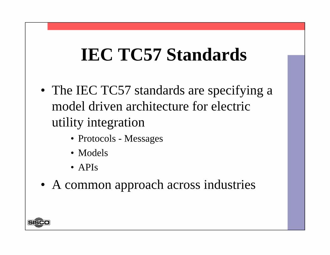
IEC TC57 Standards
• The IEC TC57 standards are specifying a model driven architecture for electric utility integration
• Protocols - Messages• Models• APIs
• A common approach across industries

GID – Generic Interface Definition Services (IEC61970-4xx)
Field Devices
CIM - Common Information Model (IEC61970-3xx)
Administrative Services
OMObject Models(IEC61850-7-3 & 7-4)
SMService Models(IEC61850-7-2)
CPCommunication Profiles &Mapping (IEC61850-8 & 9)
Application DomainsCommunicationLevel
Integrated Energy and communication System Architecture (IECSA)
FieldC
ontrol C
enter
Applications and Databases
SA
(Substation)
DE
R(D
istributed Resources)
DA
(Distribution A
utomation)
CU
S(C
ustomer)
GE
N (G
eneration)
Other …
..
CFL
Configuration Language (IE
C61850-6+)
SE
CS
ecurity (TBD
)
CN
MN
etwork M
anagement (TB
D)

ISA S.95 – IEC62264• An ISA standard for the interface between
automation and production control.• Addresses both discrete and continuous
process industries.• Specifies models and terminology for
production orders, scheduling, planning, etc.
• S.95 is just now becoming used.

CIM vs. SP95
ConductingEquipment(from Core)
Equipment(from Core)
PowerSystemResource(from Core)
RegulationSchedule
TapChanger
0..1
0.. n
+RegulationSchedule0..1
+ TapChangers
0.. n
WindingTest
HeatExchanger
TransformerWinding
0..n
1
+TapChangers
0..n
+TransformerWinding
1
1
0..n
+From_TransformerWinding1
+ From_WindingTests0..n1
0..n
+To_WindingTest1
+To_TransformeWindings0..n
PowerTransformer
0..1
1
+HeatExchanger 0..1
+PowerTransformer 1
1..n
1
+ Contains _TransformerWindings
1..n
+MemberOf_PowerTransformer
1
MaintenanceRequest
MaintenanceRequest
MaintenanceWork Order
MaintenanceWork Order
MaintenanceResponse
MaintenanceResponse
May be generated for0..n
1..1
1..1
1..1
EquipmentClass Property
EquipmentClass Property
EquipmentProperty
EquipmentProperty
EquipmentCapability TestSpecification
EquipmentCapability TestSpecification
EquipmentClass
EquipmentClass
Hasvalues for
0..n
0..n
0..n
0..n
0..n
EquipmentEquipment
EquipmentCapability Test
Result
EquipmentCapability Test
Result
0..n
0..n1..n
Hasproperties
of
Is testedby a
Maps to
Defined by
Records theexecution of
0..n
0..n May result in
0..1
May be up of Is against
Is madeagainst
0..n
0..n
Defines aprocedure forobtaining a
CIMCIM
S.95S.95

Impact of Being Model Neutral
• Increased data independence.
• Enables user specific customizations without affecting coding.
• Enables application of adapters across industries increasing 3rd party interest in supporting product based adapters.

Impact: Self Description
• Applications obtain the description of the data from the source of the data.
• Eliminates a great deal of configuration and errors.
• Improves understanding of data• Increases independence of applications from the
sources of data• LOWERS THE COST OF USING
TECHNOLOGY

Impact: Model Awareness• Applications and users can see the meaning of
data and its relationship to other data.
• Allows configuration in the context of the power system.
• Avoids arcane proprietary tag naming conventions.
• Allows model changes to be propagated automatically
• LOWERS THE COST OF USING TECHNOLOGY

Impact: Application Independence
• Application can be independent of the data required by finding what is needed in the model automatically.
• No need to preconfigure each instance of data to be operated on.
• Enables reusability of applications without configuration.
• LOWERS THE COST OF USING TECHNOLOGY

Data Dependent Application
Read TSUB23PHA4023Read TSUB23PHB4023Read TSUB23PHC4023Read TSUB24PHA6187
Read TSUB76PHB5865Read TSUB76PHC5865Read TSUB76PHA5977Read TSUB76PHB5977Read TSUB76PHC5977
.....
Read All Transformer Voltages
Other algorithms possible. But, regardless of
algorithm, programs generally contain
hard coded references to either names or tables to
access.

Data Independent ApplicationRead All Transformer Voltages
Find Next Substation
Find NextTransformer
Find NextVoltage
Read
Every name is either defined by CIM or
defined in the model

Impact: Leverage Existing Technology
• The layered approach enables utility specific functions to be added to existing generic technology that is in widespread use.
• Minimizes the utility specific technology (lower volume) required.
• LOWERS THE COST OF USING TECHNOLOGY

About Benefits & Justification
• Identify all the benefits (obvious).• Identify ALL the costs:
– Equipment– Installation– Engineering– Commissioning– Utilization Costs– Impact on External Systems– Costs to Change/Migrate in Future– Intangibles (new capability)

Identifying ALL Costs• Requires a complete view of cost.
You can’t justify a system by examining only the price.
- OR -
The benefit of a system is not in the price.

Identifying ALL Costs• Requires a longer time frame.
It is hard to justify any system by examining only the purchase price.
- OR -
Benefits are received as systems are used, not when they are purchased.

Model-Driven Cost JustificationC
ost
TimePurchase
Payback
BENEFITTraditionalApproaches
ModelDriven
Approaches

Example: Power Plant Dispatch
HMI/SCADAPackage
PLC Driver
CorporateNetwork
Control Center
1 of 32 Power Plants ICCP-TASE.2 Interface
OPC ServerOPC Client
OPC ServerOPC Client
PLCI/O
PLC Network
GeneratorExisting Systems
InterfaceAdded

Example: Plug’n Play With OPCOPC Gateway
IEC61850
OPC
Server
DNP3
OPC
Server
OPC Client APIOPC Client API
OPC Server API OPC Server API
ToIEC61850Devices
ToDNP3
Devices
Simple Gateway Using OPC

Example: Substation and EMS Integration
OPC Based Product
Substation EquipmentMaintenance Models(CIM) & Applications
AssetMgmt.Models
EMS
Utility Integration Bus
GDA server& client TSDA
GDA TSDA
Historian AdapterHistorian
ModelDatabase
(CIM)
Archive
GDA HDA DA
ICC
P
Power SystemModels (CIM)
GDA Server
GDA
Power Sys.Analysis
GDA HSDA
GDA HSDA
EquipmentModels
Power SystemModels
Can be added without disrupting existing systems.
OPCDA
GDAClient
OPCHDA

UCA – Protocols, Models, and APIs
The UCA® International Users Group is a forum where interested parties can
meet and cooperate in the implementation and usage of IEC
TC57 standards.http://www.ucainternational.org

Thank You
Ralph Mackiewicz6605 19½ Mile Road
Sterling Heights, MI 48314 USATel: +586-254-0020 x103
Fax: +586-254-0053E-Mail: [email protected]
The Standards Based Integration Company
![[MS-RAA]: Remote Authorization API Protocol€¦ · [MS-RAA]: Remote Authorization API Protocol Intellectual Property Rights Notice for Open Specifications Documentation](https://static.fdocuments.net/doc/165x107/5f8639135a180f40b773e343/ms-raa-remote-authorization-api-protocol-ms-raa-remote-authorization-api-protocol.jpg)


![[MS-TAIL]: Telephony API Internet Locator Service Protocol... · Telephony API Internet Locator Service Protocol Dynamic Directory Object Internet Locator Service (ILS). people. .](https://static.fdocuments.net/doc/165x107/5f3d1ee4f10ab21c51753c36/ms-tail-telephony-api-internet-locator-service-protocol-telephony-api-internet.jpg)