
The Red Ensign Group A CODE OF P Y C 13 36 P (T P Y C (S E ... · PDF fileREG 13-36 PASSENGER...
281
REG 13-36 PASSENGER YACHT CODE (Continued) (Page 1 of 281) (Second Edition) (January 2012) The Red Ensign Group A CODE OF PRACTICE FOR YACHTS CARRYING 13 TO 36 PASSENGERS (THE P ASSENGER Y ACHT CODE) (SECOND EDITION – JANUARY 2012) This Code of Practice applies to pleasure yachts of any size, in private use or engaged in trade, which carry more than 12 but not more than 36 passengers and which do not carry cargo.
Transcript of The Red Ensign Group A CODE OF P Y C 13 36 P (T P Y C (S E ... · PDF fileREG 13-36 PASSENGER...

REG 13-36 PASSENGER YACHT CODE (Continued)
(Page 1 of 281)
(Second Edition) (January 2012)
The Red Ensign Group
A CODE OF PRACTICE FOR YACHTS CARRYING 13 TO 36
PASSENGERS
(THE PASSENGER YACHT CODE)
(SECOND EDITION – JANUARY 2012)
This Code of Practice applies to pleasure yachts of any size, in private use or engaged in
trade, which carry more than 12 but not more than 36 passengers and which do not carry
cargo.

REG 13-36 PASSENGER YACHT CODE (Continued)
(Page 2 of 281)
(Second Edition) (January 2012)
This page is intentionally added to achieve correct pagination.

REG 13-36 PASSENGER YACHT CODE (Continued)
(Page 3 of 281)
(Second Edition) (January 2012)
Contents
CHAPTER ETC. PAGE NOS.
Front Page 1 Contents/Index 3-7 Notes to Second Edition 9-11 Preamble 13-20
Chapter 1 General: 21-35 1.1 1.2 ---
1.3 1.4 1.5 1.6 1.7
Purpose. Application. Table1-1 (LSA Scales etc.). Definitions. Survey and Certification. Casualties. Review of the Code Amendments to international Conventions and related Instruments.
21 21
23-24 25-34 34-35
35 35 35
Chapter 2 Load Lines: 37-53 2.1 2.2 2.3 2.4 2.5 2.6 2.7 2.8 2.9
2.10 2.11 2.12 2.13 2.14 2.15 2.16
Strength and Construction of Ship. Application. Subdivision and Load Line mark. Mark of Assigning Authority. Doors and Openings above the Weather Deck. Shell Openings below the Freeboard Deck. Hatchways and Coamings. Miscellaneous Openings in Freeboard and Superstructure Decks. Ventilators. Air Pipes. Scuppers, Inlets and Discharges. Side Scuttles and Windows. Garbage Chutes etc. Spurling Pipes and Cable Lockers. Freeing Ports and Recesses. Protection of the Crew.
37 37-38 38-39
39 40-42
42 42-43
44 44-45
45 45-46 46-50 50-51 51-53
53
Chapter 3 Application of Other International Conventions: 55-57 3.1 3.2 3.3 3.4 3.5 3.6 3.7
Conventions-General. Navigation Lights. Prevention of Pollution. Anti-Fouling Convention. Ballast Water Convention. Bunkers Convention. National Legislation.
55 56 56 56 56 57 57

REG 13-36 PASSENGER YACHT CODE (Continued)
(Page 4 of 281)
(Second Edition) (January 2012)
CHAPTER ETC. PAGE NOS.
Chapter 4 Construction, Subdivision and Stability: 59-111 PART I
4.1 4.2
PART II
4.3 4.4 4.5 4.6 4.7 4.8 4.9
4.10
PART III
4.11 4.12 4.13 4.14 4.15 4.16 4.17 4.18 4.19
PART IV
4.20
PART V
4.21 4.22 4.23 4.24
PART VI
4.25 4.26 4.27 4.28 4.29
GENERAL: Strength of Ship and Subdivision - General. Application of SOLAS Provisions - General. STABILITY: Intact Stability and Information. Stability Information to be Supplied to the Master. Required Subdivision Index R. Attained Subdivision Index A. Calculation of the Factor pi. Calculation of the Factor si. Permeability. Requirements Concerning Passenger Ship Stability. SUBDIVISION, WATERTIGHT AND WEATHERTIGHT INTEGRITY: Double Bottoms. Construction of Watertight Bulkheads, Initial Testing of Watertight Bulkheads etc. Peak and Machinery Space Bulkheads, Shaft Tunnels etc.; Openings in Watertight Bulkheads below the Bulkhead Deck. Openings in the Shell Plating below the Bulkhead Deck. Construction and Initial Testing of Watertight Doors, Sidescuttles etc. Construction and Initial Testing of Watertight Decks, Trunks etc. Internal Watertight Integrity above the Bulkhead Deck. SUBDIVISION LOAD LINE ASSIGNMENT: Assigning, Marking and Recording of Subdivision Load Lines. STABILITY MANAGEMENT. Damage and Control Information. Loading of Passenger Ships. Periodical Operation and inspection of Watertight Doors etc. Prevention and Control of Water Ingress etc. ALTERNATIVE SUBDIVISION AND STABILITY STANDARDS FOR PASSENGER
YACHTS NOT EXCEEDING 80 METRES IN LENGTH (L) WHERE COMPLIANCE WITH
REGULATION 6 AND 7 OF SOLAS II-1 PART B-1 PROVES IMPRACTICABLE: Floodable Length. Permeability. Permissible Length of Compartments. Special Requirements concerning Subdivision. Stability in Damaged Condition.
59-60
59-60 60
61-75
61
62-63 63
64-65 65-69 69-74
74 74-75
76-91
76-78
78 78
79-80 80-87 87-89 89-90
90 90-91
92
92
93-97
93
93-94 94
94-97
98-109
98 98-99
100-102 103-104 104-109

REG 13-36 PASSENGER YACHT CODE (Continued)
(Page 5 of 281)
(Second Edition) (January 2012)
CHAPTER ETC. PAGE NOS.
PART VII
4.30
4.31
ADDITIONAL PROVISIONS FOR VESSELS PERMITTED TO CARRY DAVIT
LAUNCHED LIFERAFTS AND MARINE EVACUATION SYSTEMS IN LIEU OF
LIFEBOATS Enhanced Survivability for Vessels provided with Davit Launched Liferafts or Davit Launched Liferafts and Marine Evacuation Systems in lieu of Lifeboats in accordance with Table 1.1. Maximum Floodable Length for Vessels of 80 meters in length and over.
110-111
110-111
111
Chapter 5 Machinery and Electrical Installations and Unattended Machinery Spaces: 113 5.1 5.2 5.3
Machinery Installations. Electrical Installations. Periodically Unattended Machinery Spaces.
113 113 113
Chapter 6 Fire Protection, Detection and Extinction: 115-178 6.1 6.2 6.3 6.4 6.5 6.6 6.7
Table 6.1 Table 6.2
6.8 6.9
6.10 6.11 6.12 6.13 6.14 6.15 6.16 6.17
Fire Safety Objectives and Functional Requirements. Probability of Ignition. Fire Growth Potential. Smoke Generation Potential and Toxicity. Detection and Alarm. Control of Smoke Spread. Containment of Fire Fire Integrity of Bulkheads separating Adjacent Spaces. Fire Integrity of Decks separating Adjacent Spaces. Fire Fighting. Structural Integrity. Notification of Crew and Passengers. Means of Escape. Operational Readiness and Maintenance. Instructions, On-board Training and Drills. Operations. Alternative Design and Arrangements. Helicopter Facilities. Protection of Garage Spaces.
115-116 116-121 121-126 126-127 127-130 130-131 132-148
138 139
148-158 158-160
160 161-166 166-167 167-169 169-170 170-171 172-176 176-178
Chapter 7 Life Saving Appliances and Arrangements: 179-206 7.1 7.2 7.3 7.4 7.5 7.6 7.7 7.8 7.9
7.10 7.11 7.12
Application. General Requirements. Stowage of Survival Craft. Stowage of Rescue Boats. Stowage of Marine Evacuation Systems. Survival Craft Launching and Recovery Arrangements. Rescue Boat Embarkation, Launching and Recovery Arrangements. Survival Craft and Rescue Boat Embarkation Arrangements. Communications. Personal Life Saving Appliances. Muster List and Emergency Instructions. Operating Instructions.
179 179 180 181 181
181-183 183
183-184 184-185 186-188 188-189
189
REG 13-36 PASSENGER YACHT CODE (Continued)
(Page 6 of 281)
(Second Edition) (January 2012)
CHAPTER ETC. PAGE NOS.
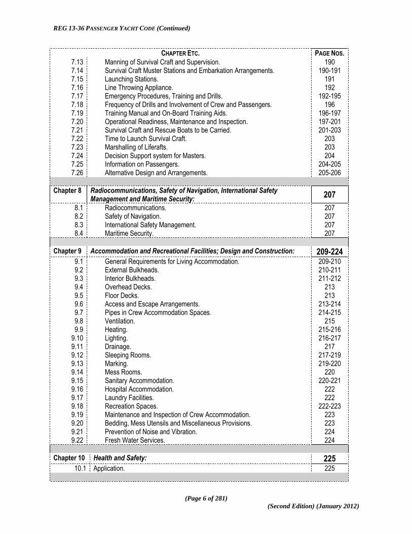
7.13 7.14 7.15 7.16 7.17 7.18 7.19 7.20 7.21 7.22 7.23 7.24 7.25 7.26
Manning of Survival Craft and Supervision. Survival Craft Muster Stations and Embarkation Arrangements. Launching Stations. Line Throwing Appliance. Emergency Procedures, Training and Drills. Frequency of Drills and Involvement of Crew and Passengers. Training Manual and On-Board Training Aids. Operational Readiness, Maintenance and Inspection. Survival Craft and Rescue Boats to be Carried. Time to Launch Survival Craft. Marshalling of Liferafts. Decision Support system for Masters. Information on Passengers. Alternative Design and Arrangements.
190 190-191
191 192
192-195 196
196-197 197-201 201-203
203 203 204
204-205 205-206
Chapter 8 Radiocommunications, Safety of Navigation, International Safety Management and Maritime Security:
207
8.1 8.2 8.3 8.4
Radiocommunications. Safety of Navigation. International Safety Management. Maritime Security.
207 207 207 207
Chapter 9 Accommodation and Recreational Facilities; Design and Construction: 209-224 9.1 9.2 9.3 9.4 9.5 9.6 9.7 9.8 9.9
9.10 9.11 9.12 9.13 9.14 9.15 9.16 9.17 9.18 9.19 9.20 9.21 9.22
General Requirements for Living Accommodation. External Bulkheads. Interior Bulkheads. Overhead Decks. Floor Decks. Access and Escape Arrangements. Pipes in Crew Accommodation Spaces. Ventilation. Heating. Lighting. Drainage. Sleeping Rooms. Marking. Mess Rooms. Sanitary Accommodation. Hospital Accommodation. Laundry Facilities. Recreation Spaces. Maintenance and Inspection of Crew Accommodation. Bedding, Mess Utensils and Miscellaneous Provisions. Prevention of Noise and Vibration. Fresh Water Services.
209-210 210-211 211-212
213 213
213-214 214-215
215 215-216 216-217
217 217-219 219-220
220 220-221
222 222
222-223 223 223 224 224
Chapter 10 Health and Safety: 225 10.1 Application. 225

REG 13-36 PASSENGER YACHT CODE (Continued)
(Page 7 of 281)
(Second Edition) (January 2012)
CHAPTER ETC. PAGE NOS.
Chapter 11 Ship-Shore Transfer of Personnel: 227-229 11.1 11.2 11.3 11.4
Tenders (Dinghies). Helicopters. Pilot Boarding Arrangements. Gangways, Passerelles, and Accommodation Ladders.
227 227-228
228 229
Chapter 12 Manning, Certification and Hours of Work. 231-239 12.1 12.2 12.3 12.4 12.5
Tables 12.6 12.7
Application. Purpose. Safe Manning. Application for a Safe Manning Document. Qualifications and Training. Manning Guidance Tables 12-1 to 12-4 Medical Fitness. Hours of Work and Rest.
231 231
231-233 233
233-238 235-238
238 239
Chapter 13 Medical Care and Carriage of Medical Stores: 241-244 13.1 13.2 13.3 13.4 13.5 13.6 13.7 13.8 13.9
Medical Care for Seafarers. Provision of On-board Medical Care. Medical Cabinet. Carriage of Medical Stores. Standards of Medical Stores. Carriage of Medical Guides. Medical Advice. Inspection of Medicines and Medical Stores. Carriage of Doctors or Medically Trained Personnel.
241 241 242 242 243 243 243 243
243-244
ANNEXES
Annex 1 Classification Societies and other Bodies appointed as Recognised Organisations. By the National Administration concerned,
245
Annex 2 Technical Standards for Helicopter Landing Areas and Helicopter Operating Standards
247-281

REG 13-36 PASSENGER YACHT CODE (Continued)
(Page 8 of 281)
(Second Edition) (January 2012)
This page has been intentionally inserted to preserve correct pagination.

REG 13-36 PASSENGER YACHT CODE (Continued)
(Page 9 of 281)
(Second Edition) (January 2012)
NOTES TO SECOND EDITION:
(i) This Second Edition of the Passenger Yacht Code has been prepared following feedback
from the yachting sector and from REG. Members, based on the operation of the Code since
the promulgation of the First Edition in November 2010.
(ii) The issues raised have been discussed within REG Technical Forum (REG-TF) and
agreement reached on what changes should be made. The opportunity has also been taken to
correct some minor typographical errors.
(iii) It has always been the intention that the Code should be revised on an annual basis and
this Second Edition represents the first of such revisions. A summary of the revisions
incorporated is given in the following Table.
TABLE SUMMARISING THE AMENDMENTS INCORPORATED IN THE SECOND EDITION: PAGE NO. SECTION ETC. NO. NATURE OF AMENDMENT ADDITIONAL INFORMATION
Front --- Inserted “Second Edition – January 2012” ---
3-7 --- Consequential revisions to Contents. ---
9-11 Notes to Second Edition.
Explanatory Notes and Summary of Amendments inserted.
---
13-20 Preamble. Paragraph 2 slightly modified to define the Code and its related terminology. In paragraph 21 the Annex VI Protocol to MARPOL (Air Pollution) and the Anti-Fouling Systems (AFS) Conventions have been added to the list of other Conventions which may need to be complied with.
--- ---
17 23 59 202
Preamble (Table P-1) 1.2 (Table 1-1) 4.1 (Table 4.1) 7.21 (Table 7.1)
The length parameters for Damaged Stability Standards and for LSA Scale have been adjusted.
The parameters were shown as equal to or less than 80M and greater than 80M and they should be less than 80M and equal to or greater than 80M. and these changes have been made.
60 4.2(2) Reference to length re-cast as “80m L (i.e. Load Line length)”.
“L” is defined in section 1.3 based on Load Line length but additional clarity has been inserted in section 4.2(2) for the avoidance of doubt in that section.
70 4.8(4) Typographical error. The factor “K” was missing from the first formula and this has been added.
---
73 4.8(14) Typographical error. The reference to 4.7(2) in the fourth line was incorrect and has been changed to the correct reference of 4.8(2).
---
REG 13-36 PASSENGER YACHT CODE (Continued)
(Page 10 of 281)
(Second Edition) (January 2012)
PAGE NO. SECTION ETC. NO. NATURE OF AMENDMENT ADDITIONAL INFORMATION
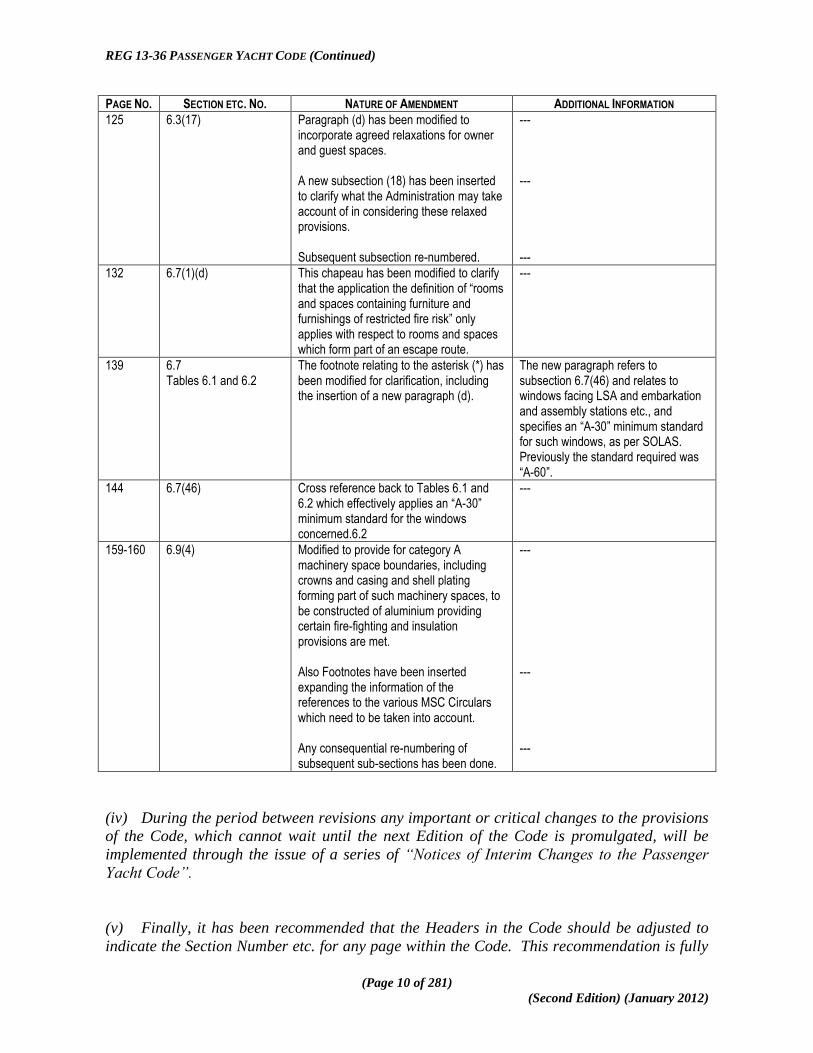
125 6.3(17) Paragraph (d) has been modified to incorporate agreed relaxations for owner and guest spaces. A new subsection (18) has been inserted to clarify what the Administration may take account of in considering these relaxed provisions. Subsequent subsection re-numbered.
--- --- ---
132 6.7(1)(d) This chapeau has been modified to clarify that the application the definition of “rooms and spaces containing furniture and furnishings of restricted fire risk” only applies with respect to rooms and spaces which form part of an escape route.
---
139 6.7 Tables 6.1 and 6.2
The footnote relating to the asterisk (*) has been modified for clarification, including the insertion of a new paragraph (d).
The new paragraph refers to subsection 6.7(46) and relates to windows facing LSA and embarkation and assembly stations etc., and specifies an “A-30” minimum standard for such windows, as per SOLAS. Previously the standard required was “A-60”.
144 6.7(46) Cross reference back to Tables 6.1 and 6.2 which effectively applies an “A-30” minimum standard for the windows concerned.6.2
---
159-160 6.9(4) Modified to provide for category A machinery space boundaries, including crowns and casing and shell plating forming part of such machinery spaces, to be constructed of aluminium providing certain fire-fighting and insulation provisions are met. Also Footnotes have been inserted expanding the information of the references to the various MSC Circulars which need to be taken into account. Any consequential re-numbering of subsequent sub-sections has been done.
--- --- ---
(iv) During the period between revisions any important or critical changes to the provisions
of the Code, which cannot wait until the next Edition of the Code is promulgated, will be
implemented through the issue of a series of “Notices of Interim Changes to the Passenger
Yacht Code”.
(v) Finally, it has been recommended that the Headers in the Code should be adjusted to
indicate the Section Number etc. for any page within the Code. This recommendation is fully

REG 13-36 PASSENGER YACHT CODE (Continued)
(Page 11 of 281)
(Second Edition) (January 2012)
accepted but due to the complex character of what is also a very large document, it would
take some time to complete the task efficiently. Rather than delay the promulgation of this
Second edition therefore, it is intended to deal with the Headers issue in time for the
promulgation of the Third Edition.

REG 13-36 PASSENGER YACHT CODE (Continued)
(Page 12 of 281)
(Second Edition) (January 2012)
This page has been intentionally inserted to preserve correct pagination.

REG 13-36 PASSENGER YACHT CODE (Continued)
(Page 13 of 281)
(Second Edition) (January 2012)
Preamble (The Preamble is provided for explanatory purposes and is not part of the Code provisions)
1. It is widely recognised that it has become increasingly impractical to apply to
pleasure yachts International Convention standards and requirements of the major
operational Conventions of the International Maritime Organization (IMO), which have been
developed and have evolved to deal with merchant cargo ships and passenger ships. With
respect to non-passenger pleasure yachts, these difficulties have been addressed under the
Large Commercial yacht Code (LY2) which deals with pleasure vessels engaged in trade
carrying 12 passengers or less and which are less than 3000 gross tonnage.
2. In a similar vein, this Code (The Code of Practice for Yachts Carrying 13 to 36
Passengers”) hereinafter referred to as “the Passenger yacht Code” or “the Code”, seeks to
rationalise the requirements and standards to be met by a pleasure yacht of any size which
carries more than 12 but not more than 36 passengers on international voyages, particularly
with respect to the International Convention for the Safety of Life at Sea, 1974 (SOLAS 1974),
as amended, the International Convention on Load Lines, 1966 (LL 1966), as amended and
the International Convention on Standards of Training, Certification and Watchkeeping, 1978
(STCW 1978), as amended, including applicable Protocols and Codes thereto.
3. The development of the Code is therefore based on the consideration that full
compliance with some of the provisions of the conventions referred to in paragraph 2 as they
apply to commercial merchant passenger ships is unreasonable and in some instances
disproportionately onerous in terms of design and cost compared to the incremental increase
in safety levels achieved for yachts, given that pleasure yachts have a very different operating
pattern (for the most part occasional voyages in defined weather conditions or operating
areas) when compared to a typical commercial passenger ship which usually operates 24/7
on a tight schedule. Thus, for the avoidance of doubt, the Code is intended to cater
exclusively to the pleasure and leisure sector of the market and it is not intended to apply to
commercial cruise, excursion or ferry passenger (including passenger/cargo vessels) sectors
of the industry. Vessels to which this Code applies need not be considered as High Speed
Craft.
4. The Code has been developed by the Members of the Red Ensign Group1 (REG)
through its Technical Forum and applies to pleasure yachts of any size which are in private
use or engaged in trade and which do not carry cargo and carry 13 to 36 passengers.
1 The Members of the Red Ensign Group (REG) consist of the Maritime Administrations of the United
Kingdom, Anguilla, Bermuda, British Virgin Islands, Cayman Islands, Falkland Islands, Gibraltar, Guernsey,
Isle of Man, Jersey, Montserrat, Turks and Caicos, and St. Helena.

REG 13-36 PASSENGER YACHT CODE (Continued)
(Page 14 of 281)
(Second Edition) (January 2012)
5. The Code sets out technical, safety and operational standards appropriate to the size
and operation of the vessels expected to operate under this Code. The standards incorporated
in the Code are largely based on the international conventions applying to commercial
vessels with the inclusion of equivalencies where it is not reasonable or practicable to comply
with the conventions and where there is an opportunity to enhance safety. Compliance with
the standards required by the Code will entitle a yacht to be issued with the appropriate
Passenger Certificate under the relevant international Convention or under national law as
the case may be.
6. Table P-1 below (reproduced from section 1.2 of the Code) sets out the philosophy
applied in terms of the category of pleasure yacht and its area of operation against the
standards of stability and survivability, scale of Life Saving Appliances (LSA), maximum
persons carried and related parameters. The structure also provides a “stepped approach”
to be adopted in ascertaining appropriate standards to be applied to the various categories of
yacht and their operational areas. In general terms, where the carriage of Davit Launched
Liferafts (DLLs) or Marine Evacuation Systems (MESs) are permitted in lieu of lifeboats,
enhanced standards of subdivision, damaged stability and fire protection are applied as per
the relevant Chapters of the Code, bearing in mind the relationships between subdivision,
damaged stability and survivability of the yacht, thus applying the current philosophy of the
ship being its own best survival craft.
7. With respect to structural standards it is a pre-requisite that a vessel aspiring to be
Code compliant will be Classed and maintained in Class as a passenger ship with one of the
Classification Societies authorised to act as a Recognized Organization (RO) by the REG.
8. In regard to enhanced fire protection, detection and extinction, for example, a fully
addressable fire detecting and extinguishing system is required in all ships to which the Code
applies.
9. In parallel with the “stepped” approach referred to in paragraph 6 the Code also, with
respect to a Passenger Yacht 2, takes account of the provisions in SOLAS (Chapter II-2A,
Regulation .4.1 and Chapter IIIA, Regulation 1.4.1) which allow for exemptions from the
requirements with respect to the sheltered nature and conditions voyages where the ship is
not more than 20 nautical miles from land.
10. The option remains for any yacht to which the Code applies to carry lifeboats and
thereby operate in a higher category or less restricted operational area.

REG 13-36 PASSENGER YACHT CODE (Continued)
(Page 15 of 281)
(Second Edition) (January 2012)
11. The current scope of the Code does not include provisions for sailing vessels. Whilst it
is intended to include such provisions in a later version of this Code, sailing vessels are
excluded from the current version.
12. The Code also does not currently include provisions for composite vessels. Therefore,
whilst it is intended to include such provisions in a later version of the Code, vessels
constructed from composite or other materials are excluded from the current version.
13. Where reference is made to the National Requirements in an Annex, individual
members of the REG can provide guidance appropriate to their national regulations and
policy.
14. Where the relevant provisions of SOLAS 74 or LL 66 (as amended) apply in part but
some provisions have been modified then the text of all of that Part of the Convention has
been incorporated into the body text of the Code for consistency and ease of reference. To
readily determine what is “new” drafting and what, in essence, are unmodified Convention
provisions, then in the body text of the Code-
(a) modified or alternative provisions are shown, in italics; and
(b) unchanged Convention provisions are shown in plain text.
15. Again for consistency and to achieve a uniform drafting style, the wording of some of
the unchanged Convention provisions has been adjusted, but the actual provisions remain
unchanged and so the body text is in plain text.
16. Where the relevant provisions of a part of SOLAS 1974 or LL 1966 apply without any
modification, those provisions are in general incorporated into the Code through appropriate
cross references.

REG 13-36 PASSENGER YACHT CODE (Continued)
(Page 16 of 281)
(Second Edition) (January 2012)
This page has been intentionally inserted to preserve correct pagination.

REG 13-36 PASSENGER YACHT CODE (Continued)
(Page 17 of 281)
(Second Edition) (January 2012)
(TABLE P-1)
PY CODE TABLE SUMMARISING CATEGORIES OF PASSENGER YACHT AND STANDARDS OF STABILITY AND
SURVIVABILITY, LSA SCALES, MAXIMUM PERSONS CARRIED AND OTHER RELATED MATTERS.
CATEGORY
OF
PASSENGER
YACHT
OPERATIONAL AREA
DAMAGED
STABILITY
STANDARDS
APPLICABLE2
ENHANCED
SURVIVABILITY3
LSA SCALE4
MA
XIM
UM
PE
RS
ON
S
FIRE PROTECTION ADDITIONAL
COMMENTS
<80 M ≥80 M <80 M ≥80 M <80 M AND
>500 GT
Pleasure Vessel not Engaged in
Trade
Unlimited5
D --- 300%
DLLR & MES
99
In addition to the normally applicable requirements, fully addressable fire detection and fire suppression systems are to be provided.
See also Note6
P ---
300% DLLR &
MES
99
2 D = Deterministic method. P = Probabilistic method.
3 2 Compartment Enhanced Survivability as set out in Chapter 4, Part IV of the Code.
4 The Table shows the arrangements for Passenger Yachts carrying Davit Launched Life Rafts (DLLRs) or a combination of DLLRs and Marine Evacuation
Systems (MESs) such that-
(a) MESs are not permitted as the sole means of abandonment;
(b) in the event of the loss of any one survival craft there will be at least 100% capacity remaining on either side; and
(c) in all cases dry shod evacuation is required. 5 Unlimited Area does not include the Polar Regions.
6 Any passenger yacht operating in the Polar Regions is required to carry Lifeboats as per SOLAS, Chapter III requirements and shall also adhere, inter alia, to
the IMO Guidelines for Polar Regions.

REG 13-36 PASSENGER YACHT CODE (Continued)
(Page 18 of 281)
(Second Edition) (January 2012)
CATEGORY
OF
PASSENGER
YACHT
OPERATIONAL AREA
DAMAGED
STABILITY
STANDARDS
APPLICABLE2
ENHANCED
SURVIVABILITY3
LSA SCALE4
MA
XIM
UM
PE
RS
ON
S
FIRE PROTECTION ADDITIONAL
COMMENTS
<80 M ≥80 M <80 M ≥80 M <80 M AND
>500 GT
Passenger Yacht
Unrestricted (Engaged in
Trade)
Unlimited5
D 2 Compartment
Enhanced.
300% DLLR &
MES 99
In addition to the normally applicable requirements, fully addressable fire detection and fire suppression systems are to be provided.
See also Note7
P 2 Compartment
Enhanced.
300% DLLR &
MES 508
PY1 Prescribed International
Voyage9
D 2 Compartment
Enhanced. 300% DLLR &
MES 99
In addition to the normally applicable requirements, fully addressable fire detection and fire suppression systems are to be provided.
P 2 Compartment
Enhanced. 300% DLLR &
MES 99
PY2
PY 2 Area is within 60 n.m. of a safe haven and not more than 20 n.m. from land in weather conditions not exceeding wind force 6 and sea state 5 on Beaufort scale.
D --- 300% DLLR &
MES 99
In addition to the normally applicable requirements, fully addressable fire detection and fire suppression systems are to be provided.
7 A passenger Yacht of less than 500 gross tonnage which carries less than 200 persons may, under SOLAS Chapter III, Part B, Section II, Regulation 21.1-1.4,
carry 300% (150% each side) inflatable or rigid liferafts complying with Regulation 4.2 or 4.3 of Chapter IV of the LSA Code providing other applicable
provisions of the relevant Conventions are complied with. 8 Where a Passenger Yacht Unlimited (PY-U) of over 80 metres carries more than 50 persons then Lifeboats are required in accordance with SOLAS.
9 A Prescribed International Voyage as defined in the Code is a voyage during which the Yacht is not more than 200 nautical miles from a port or place in
which the passengers and crew could be placed in safety and within a geographical area which limits the length of the voyage to a maximum of 1000 nautical
miles from the initial point of departure, as specified in any Certificate issued in accordance with the Code with respect to the ship.

REG 13-36 PASSENGER YACHT CODE (Continued)
(Page 19 of 281)
(Second Edition) (January 2012)
17. Notwithstanding that the Code applies to yachts carrying up to 99 persons, the Code
may still be applied where this number is exceeded provided that-
(a) the number of persons does not exceed 120;
(b) the yacht is fitted with approved lifeboats, davits and launching arrangements
in accordance with SOLAS 74 (as amended);
(c) a qualified doctor is carried; and
(d) the number of passengers does not exceed 36.
Applications to exceed the 99 maximum persons would be assessed on a case by case basis.
18. The structure of the Code in terms of Headings, Sections etc. is as follows-
(a) the main divisions are Chapters;
(b) in each Chapter consecutive “sections”, which each have a sub-heading
attached to them, are numbered consecutively preceded by the Chapter number
– e.g., in Chapter 1 the sections would be 1.1,1.2, 1.3 etc.;
(c) sections are further divided into subsections numbered consecutively as (1),
(2), (3) etc. except where, occasionally, the section does not require any such
division;
(d) subsections may be further subdivided into paragraphs labelled (a), (b) (c)
etc.;
(e) where necessary, paragraphs may be further divided into subparagraphs
numbered (i), (ii), (ii) etc.;
(f) where occasionally a further sub-division is necessary, sub-subparagraphs are
used labelled (ba), (bb), (bc) etc.
(g) due to its complex structure, Chapter 4 has also been subdivided into Parts;
(h) finally, for consistency and clarity, cross references are couched in terms of
the Chapter and section number to the required level (e.g. section 4.49(1)(a)
(ii) refers to Chapter 4, section 49, subsection (1), paragraph (a).
subparagraph (ii), except where a shortened reference does not introduce any
doubt.
19. It should also be borne in mind that the applicable provisions of other International
Conventions and related Instruments, as well as the provisions of applicable national
legislation, are to be applied as appropriate, except where equivalent or alternative
provisions are provided for under the Code, in which case the Code provisions will apply. In
this regard it is not permitted to apply only selected provisions of the Code on a “pick and
mix” basis. Where the Code is applied, it shall, to that extent, be applied in full.
REG 13-36 PASSENGER YACHT CODE (Continued)
(Page 20 of 281)
(Second Edition) (January 2012)
20. In setting out the required standards of safety and operation, within the framework of
SOLAS 1974, LL 66 and STCW 78, as amended, which are appropriate to the size and area of
operation of the vessel, due cognizance is taken of the provisions in those Conventions for
equivalent or alternative provisions taking into account the functional requirements
involved10
.
21. Other International Conventions and Instruments which may need to be complied with
include but are not necessarily limited to-
a. International Convention on Tonnage Measurement of Ships, 1969, as
amended (TONNAGE 1969);
b. Protocols of 198811
relating to International Convention on Load Lines, 1966,
as amended (LL PROT 1988) and the International Convention for the Safety
of Life at Sea, 1974, as amended (SOLAS Protocol 1988);
c. International Convention for the Prevention of Pollution from Ships, 1973, as
amended by the Protocol relating thereto of 1978, as further amended
(MARPOL 73/78);
d. International Convention on Standards of Training, Certification and
Watchkeeping for Seafarers, 1978, as amended (STCW 1978);
e. Convention on the International Regulations for the Prevention of Collisions at
Sea, 1972, as amended (COLREG 1972);
f. Maritime Labour Convention, 2006;
g. International Convention on the control of Harmful Anti-fouling Systems on
Ships, 2001;
h. Ballast Water Management Convention, 2004;
i. International Convention on Civil Liability for Bunker Oil Pollution Damage,
2001;
j. Protocol of 1997 to MARPOL (Annex VI – Air Pollution); and
k. International Convention on the Control of Harmful Anti-Fouling Systems on
Ships.
10
In this regard, account should be taken of the early application (for ships constructed on or after 05 December
2008) of the International Code on Intact Stability, 2008 which was adopted under IMO resolution
MSC.267(85), as referenced by MSC.1/Circ.1292 dated 09 December 2008‘ as well as the entry into force of
the amendments to SOLAS 74 (as amended) as adopted by IMO Resolution MSC.269(85).
11
Introduces the Harmonized System of Survey and Certification (HSSC).
REG 13-36 PASSENGER YACHT CODE (Continued)
(Page 21 of 281)
(Second Edition) (January 2012)
CHAPTER 1
GENERAL
1.1 Purpose:
The purpose of the 13-36 Passenger Yacht Code (PYC), hereinafter referred to as the Code, is
to provide design criteria, construction standards and other safety measures for yachts
carrying 13 to 36 passengers so as to minimise the risk to such ships, to the personnel on
board and to the environment. The criteria are largely based on the Conventions and
Instruments referred to in the preamble to this Code, but have been modified where deemed
appropriate.
1.2 Application:
(1) Unless otherwise expressly stated in the national annex the Code applies only to Red
Ensign Group pleasure yachts engaged on international voyages whilst carrying more
than 12 but not more than 36 passengers with a maximum number of persons not more
than 99 and which do not carry cargo.
(2) This Code applies to ships, designed constructed surveyed and certified in accordance
with the requirements of this Code. Existing vessels may apply for certification in
accordance with the Code; however the Code will apply to such vessels in the same
way as it applies to new vessels.
(3) Subject to subsection (4), all ships which undergo repairs, alterations, modifications
and outfitting related thereto shall continue to comply with at least the requirements
previously applicable to these ships.
(4) Any ship, whenever built, which is converted to a passenger yacht, or undergoes
repairs, alterations and modifications which substantially alter the dimensions of the
ship or the passenger accommodation spaces, or substantially increase the ship‟s
service life, shall be treated as a passenger yacht constructed on the date on which
such conversion, repairs, alterations or modifications commenced.
(5) Table 1.1 sets out the general relationships between the type of pleasure yacht, its
area of operation and the applicable standards with respect to Life Saving Appliances
(LSA) and stability.

REG 13-36 PASSENGER YACHT CODE (Continued)
(Page 22 of 281)
(Second Edition) (January 2012)
This page is intentionally added to achieve correct pagination.

REG 13-36 PASSENGER YACHT CODE (Continued)
(Page 23 of 281)
(Second Edition) (January 2012)
TABLE 1-1
PY CODE TABLE SUMMARISING CATEGORIES OF PASSENGER YACHT AND STANDARDS OF STABILITY AND
SURVIVABILITY, LSA SCALES, MAXIMUM PERSONS CARRIED AND OTHER RELATED MATTERS.
CATEGORY
OF
PASSENGER
YACHT
OPERATIONAL
AREA
DAMAGED
STABILITY
STANDARDS
APPLICABLE12 ENHANCED
SURVIVABILITY13
LSA SCALE14
MA
XIM
UM
PE
RS
ON
S
FIRE PROTECTION ADDITIONAL
COMMENTS
<80 M ≥80 M <80 M ≥80 M <80 M
AND >500
GT
Pleasure Vessel not Engaged in
Trade Unlimited15
D --- 300%
DLLR & MES
99
In addition to the normally applicable requirements, fully addressable fire detection and fire suppression systems are to be provided.
See also Note16
P ---
300% DLLR &
MES
99
12
D = Deterministic method. P = Probabilistic method. 13
2 Compartment Enhanced Survivability as set out in Chapter 4, Part VI of the Code. 14
The Table shows the arrangements for Passenger Yachts carrying Davit Launched Life Rafts (DLLRs) or a combination of DLLRs and Marine Evacuation
Systems (MESs) such that-
(d) MESs are not permitted as the sole means of abandonment;
(e) in the event of the loss of any one survival craft there will be at least 100% capacity remaining on either side; and
(f) in all cases dry shod evacuation is required. 15
Unlimited Area does not include the Polar Regions. 16
Any passenger yacht operating in the Polar Regions is required to carry Lifeboats as per SOLAS, Chapter III requirements and shall, inter alia, also adhere to
the IMO Guidelines for Polar Regions.

REG 13-36 PASSENGER YACHT CODE (Continued)
(Page 24 of 281)
(Second Edition) (January 2012)
CATEGORY
OF
PASSENGER
YACHT
OPERATIONAL
AREA
DAMAGED
STABILITY
STANDARDS
APPLICABLE12 ENHANCED
SURVIVABILITY13
LSA SCALE14
MA
XIM
UM
PE
RS
ON
S
FIRE PROTECTION ADDITIONAL
COMMENTS
<80 M ≥80 M <80 M ≥80 M <80 M
AND >500
GT
Passenger Yacht
Unrestricted (Engaged in
Trade)
Unlimited5
D 2 Compartment
Enhanced.
300% DLLR &
MES 99
In addition to the normally applicable requirements, fully addressable fire detection and fire suppression systems are to be provided.
See also Note17
P 2 Compartment
Enhanced.
300% DLLR &
MES 5018
PY1 Prescribed
International Voyage19
D 2 Compartment
Enhanced. 300% DLLR &
MES 99
In addition to the normally applicable requirements, fully addressable fire detection and fire suppression systems are to be provided.
P 2 Compartment
Enhanced. 300% DLLR &
MES 99
PY2
PY 2 Area is within 60 n.m. of a safe haven and not more than 20 n.m. from land in weather conditions not exceeding wind force 6 and sea state 5 on Beaufort scale.
D --- 300% DLLR &
MES 99
In addition to the normally applicable requirements, fully addressable fire detection and fire suppression systems are to be provided.
P --- 300% DLLR &
MES 99
17
A passenger ship of less than 500 gross tonnage and carrying less than 200 persons may, under Regulation 21-1 of SOLAS, carry 300% DLLRs and MESs
but this is based also on compliance with other applicable provisions of the relevant Conventions. 18
Where a Passenger Yacht Unlimited (PY-U) of over 80 metres carries more than 50 persons then Lifeboats are required in accordance with SOLAS. 19
A Prescribed International Voyage as defined in the Code is a voyage during which the Yacht is not more than 200 nautical miles from a port or place in
which the passengers and crew could be placed in safety and within a geographical area which limits the length of the voyage to a maximum of 1000 nautical
miles from the initial point of departure, as specified in any Certificate issued in accordance with the Code with respect to the ship.

REG 13-36 PASSENGER YACHT CODE (Continued)
(Page 25 of 281)
(Second Edition) (January 2012)
1.3 Definitions:
(1) For the purpose of this Code, unless expressly provided otherwise, the terms used
therein have the meanings defined in this section- (Note: where a definition is not
contained within this Code, guidance should be taken from definitions within the
applicable International conventions)-
““A” Class divisions” means those divisions formed by bulkheads and decks which
comply with the following criteria-
(a) they are constructed of steel or other equivalent material;
(b) they are suitably stiffened;
(c) they are insulated with approved non-combustible materials such that the
average temperature of the unexposed side will not rise more than 140°C
above the original temperature, nor will the temperature, at any one point,
including any joint, rise more than 180°C above the original temperature,
(d) of smoke and flame to the end of the one-hour standard fire test; and
(e) the Administration has required a test of a prototype bulkhead or deck in
accordance with the Fire Test Procedures Code to ensure that it meets the
above requirements for integrity and temperature rise;
―accommodation spaces‖ means those spaces used for public spaces, corridors,
lavatories, cabins, offices, hospitals, cinemas, game and hobby rooms, barber shops,
pantries containing no cooking appliances and similar spaces.
―aft terminal‖ means the aft limit of the subdivision length;
―aft perpendicular‖ means the perpendicular taken at the after end of length (L);
“amidship” means at the middle of the length (L);
―anti-exposure suit‖ means a protective suit designed for use by rescue boat crews and
marine evacuation system parties;
―atrium‖ means a public spaces within a single main vertical zone spanning three or
more open decks;
―“B” class divisions‖ means those divisions, referred to as ―B-15‖ or ―B-0‖, formed by
bulkheads, decks, ceilings or linings which comply with the following criteria-
(a) they are constructed of approved non-combustible materials and all materials
used in the construction and erection of "B" class divisions are non-
combustible, with the exception that combustible veneers may be permitted
provided they meet other appropriate requirements of this Chapter;
(b) they have an insulation value such that the average temperature of the
unexposed side will not rise more than 140°C above the original temperature,
nor will the temperature at any one point, including any joint, rise more than
225°C above the original temperature, within the time listed below-

REG 13-36 PASSENGER YACHT CODE (Continued)
(Page 26 of 281)
(Second Edition) (January 2012)
TYPE OF “B CLASS” DIVISION
MINIMUM TIME FOR WHICH
UNEXPOSED SIDE HAS TO REMAIN
BELOW SPECIFIED LIMITS
class "B-15" 15 minutes
class "B-0" 0 minutes
(c) they are so constructed as to be capable of preventing the passage of flame to
the end of the first half hour of the standard fire test; and
(d) the Administration has required a test of a prototype division in accordance
with the Fire Test Procedures Code to ensure that it meets the above
requirements for integrity and temperature rise;
―breadth‖ or ―B‖ means the maximum breadth of the ship, measured amidships to the
moulded line of the frame in a ship with a metal shell and to the outer surface of the hull
in a ship with a shell of any other material, unless expressly provided otherwise;
―bulkhead deck‖ means the uppermost deck up to which the transverse watertight
bulkheads are carried;
―Bunkers Convention‖ means the International Convention on Civil Liability for Bunker
Oil Pollution Damage, 2001, as may be amended from time to time;
“cabin balcony‖ means an open deck space which is provided for the exclusive use of
the occupants of a single cabin and has direct access from such a cabin;
““C” class division” means a division constructed of approved non-combustible
materials which may not meet either requirements relative to the passage of smoke and
flame nor limitations relative to the temperature rise and includes combustible veneers
are provided they meet the requirements of this Chapter;
“cargo ship” means, for the purposes of this Code, any ship which is not a passenger
ship or a pleasure yacht;
―central control station‖ means a control station in which the following control and
indicator functions are centralised-
(a) fixed fire detection and fire alarm systems;
(b) automatic sprinkler, fire detection and fire alarm systems;
(c) fire door indicator panels;
(d) fire door closure;
(e) watertight door indicator panels;
(f) watertight door closures;
(g) ventilation fans;
(h) general/fire alarms;
(i) communication systems including telephones; and
(j) microphones to public address systems;

REG 13-36 PASSENGER YACHT CODE (Continued)
(Page 27 of 281)
(Second Edition) (January 2012)
―certificated person‖ means a person who holds a certificate of proficiency in survival
craft issued under the authority of, or recognised as valid by, the Administration in
accordance with the requirements of the International Convention on Standards of
Training, Certification and Watchkeeping for Seafarers, in force; or a person who holds
a certificate issued or recognised by the Administration of a State not a Party to that
Convention for the same purpose as the convention certificate;
―Code” means Code of Practice for Pleasure Yachts Carrying 13 to 36 Passengers (i.e.
this Code);
―combustible material‖ means any material other than a non-combustible material;
―continuous "B" class ceilings or linings‖ means those "B" class ceilings or linings
which terminate at an "A" or "B" class division;
―continuously manned central control station‖ means a central control station which is
continuously manned by a responsible member of the crew;
―control stations‖ means those spaces in which the ship's radio or main navigating
equipment or the emergency source of power is located or where the fire recording or
fire control equipment is centralised; spaces where the fire recording or fire control
equipment is centralised are also considered to be a fire control station;
“deepest subdivision draft” or “(ds)” means the waterline which corresponds to the
summer load line draft of the ship;
“design pressure” means the hydrostatic pressure for which each structure or appliance
assumed watertight in the intact and damage stability calculations is designed to
withstand;
―detection‖ means the determination of the location of survivors or survival craft;
―draft” or”(d)‖ means the vertical distance from the keel line at mid-length to the
waterline in question;
―embarkation ladder‖ means the ladder provided at survival craft embarkation stations
to permit safe access to survival craft after launching;
―emergency source of electrical power‖ means the emergency source of electrical power
required by SOLAS, Chapter II-1; regulation 42;
“engaged in trade” means, for the purposes of the Code, the carriage by a yacht of
more than 12 but not more than 36 passengers for reward or remuneration under a
charter or hire agreement;
―Fire Safety Systems Code‖ means the International Code for Fire Safety Systems as
adopted by the Maritime Safety Committee of the IMO by resolution MSC.98 (73), as
may be amended by the IMO, provided that such amendments are adopted, brought into
force and take effect in accordance with the provisions of article VIII of the present
Convention concerning the amendment procedures applicable to the Annex to the
Convention other than Chapter I thereof;
―Fire Test Procedures Code‖ means the International Code for Application of Fire Test
Procedures as adopted by the Maritime Safety Committee of the IMO by resolution

REG 13-36 PASSENGER YACHT CODE (Continued)
(Page 28 of 281)
(Second Edition) (January 2012)
MSC.61(67), as may be amended by the IMO, provided that such amendments are
adopted, brought into force and take effect in accordance with the provisions of article
VIII of the present Convention concerning the amendment procedures applicable to the
Annex to the Convention other than Chapter I thereof;
―flashpoint‖ means the temperature in degrees Celsius (closed cup test) at which a
product will give off enough flammable vapour to be ignited, as determined by an
approved flashpoint apparatus;
―float-free launching‖ means that method of launching a survival craft whereby the craft
is automatically released from a sinking ship and is ready for use;
―forward perpendicular‖ means the perpendicular taken at the forward end of the length
(L) such that the perpendicular coincides with the fore side of the stem on the waterline
on which the length is measured;
―forward terminal‖ means the forward limit of the subdivision length;
“freeboard” in relation to a freeboard assigned to a ship means the distance measured
vertically downwards amidships from the upper edge of the deck line to the upper edge
of the related load line;
―freeboard deck‖ means, subject to paragraphs (a) to (d) below, the uppermost complete
deck exposed to weather and sea, which has permanent means of closing all openings in
the weather part thereof, and below which all openings in the sides of the ship are fitted
with permanent means of watertight closing-
(a) in a ship having a discontinuous freeboard deck, the lowest line of the exposed
deck and the continuation of that line parallel to the upper part of the deck is
taken as the freeboard deck; and
(b) at the option of the owner and subject to the approval of the Administration, a
lower deck may be designated as the freeboard deck provided it is a complete
and permanent deck continuous in a fore and aft direction at least between the
machinery space and peak bulkheads and continuous athwartships, provided
that-
(c) when this lower deck is stepped the lowest line of the deck and the
continuation of that line parallel to the upper part of the deck is taken as the
freeboard deck;
(d) when a lower deck is designated as the freeboard deck, that part of the hull
which extends above the freeboard deck is treated as a superstructure so far as
concerns the application of the conditions of assignment and the calculation of
freeboard and it is from this deck that the freeboard is calculated.
“garage spaces” means those enclosed spaces above and below the bulkhead deck used
for the storage of pleasure craft, vehicles, jet skis or any other such engine driven units;
―general emergency alarm system‖ means the general emergency alarm system
complying with the requirements of Chapter VII, 7.2.1 the LSA Code;
―helicopter facility‖ means a helideck including any refuelling and hangar facilities;

REG 13-36 PASSENGER YACHT CODE (Continued)
(Page 29 of 281)
(Second Edition) (January 2012)
―helideck‖ means a purpose-built helicopter landing area located on a ship including all
structure, fire-fighting appliances and other equipment necessary for the safe operation
of helicopters;
―ILO‖ means the International Labour Organisation;
―immersion suit‖ means a protective suit which reduces the body heat loss of a person
wearing it in cold water;
―IMO‖ means the International Maritime Organization;
―inflatable appliance‖ means an appliance which depends upon non-rigid, gas-filled
chambers for buoyancy and which is normally kept uninflated until ready for use;
―inflated appliance‖ means an appliance which depends upon non-rigid, gas-filled
chambers for buoyancy and which is kept inflated and ready for use at all times;
―Intact Stability Code, 2008‖ means the International Code on Intact Stability, 2008
(2008 IS Code)20
;
―keel line‖ means a line parallel to the slope of the keel passing amidships through-
(a) the top of the keel at centreline or line of intersection of the inside of shell
plating with the keel if a bar keel extends below that line, on a ship with a
metal shell; or
(b) in wood and composite ships, the distance is measured from the lower edge of
the keel rabbet and when the form at the lower part of the midship section is of
a hollow character, or where thick garboards are fitted, the distance is
measured from the point where the line of the flat of the bottom continued
inward intersects the centreline amidships;
―launching appliance or arrangement‖ means an arrangement for transferring a survival
craft or rescue boat from its stowed position safely to the water;
―Length” or “(L)‖ in relation to a ship means 96% of the total length on a waterline at
85% of the least moulded depth measured from the top of the keel, or the length from
the fore-side of the stem to the axis of the rudder stock on that waterline, if that be
greater. In ships designed with a rake of keel the waterline on which this is measured
shall be parallel to the designed waterline;
―light service draft” or “(dl)‖ means the service draft corresponding to the lightest
anticipated loading and associated tankage, including such ballast as may be necessary
for stability and/or propeller immersion and the full complement of passengers and crew
on board;
―lightest seagoing condition‖ means the loading condition with the ship on even keel,
with 10% stores and fuel remaining and with the full number of passengers and crew
and their luggage;
20
As adopted by IMO Circular MSC.267(85). This revised Code includes a mandatory Part A and a
recommendatory Part B. Also included in Part A are Severe Wind and Weather Rolling Criteria.

REG 13-36 PASSENGER YACHT CODE (Continued)
(Page 30 of 281)
(Second Edition) (January 2012)
―lightweight‖ means the displacement of a ship in tonnes without, fuel, lubricating oil,
ballast water, fresh water and feedwater in tanks, consumable stores, and passengers and
crew and their effects;
“Load Line Convention” means the International Convention on Load Lines, 1966, as
amended by the Protocol of 1988 relating thereto and as otherwise be amended by the
IMO;
―low flame-spread‖ means that the surface thus described will adequately restrict the
spread of flame, this being determined in accordance with the Fire Test Procedures
Code;
―LSA Code‖ means the International Life-Saving Appliance (LSA) Code adopted by the
Maritime Safety Committee of the IMO by resolution MSC.48(66), as it may be
amended by the IMO;
“machinery rooms‖ means spaces between the watertight boundaries of a room
containing the main and auxiliary propulsion machinery, including boilers, generators
and electric motors primarily intended for propulsion; provided that in the case of
unusual arrangements, the Administration may define the limits of the machinery
rooms;
―machinery spaces of category A‖ means those spaces and trunks to such spaces which
contain either-
(a) internal combustion machinery used for main propulsion;
(b) internal combustion machinery used for purposes other than main propulsion
where such machinery has in the aggregate a total power output of not less
than 375 kW; or
(c) any oil-fired boiler or oil fuel unit, or any oil-fired equipment other than
boilers, such as inert gas generators, incinerators, etc.;
―machinery spaces‖ means machinery spaces of category A and other spaces containing
propulsion machinery, boilers, oil fuel units, steam and internal combustion engines,
generators and major electrical machinery, oil filling stations, refrigerating, stabilising,
ventilation and air conditioning machinery, and similar spaces, and trunks to such
spaces;
―main vertical zones‖ means those sections into which the hull, superstructure and
deckhouses are divided by "A" class divisions, the mean length and width of which, on
any deck, does not in general exceed 40 metres;
―marine evacuation system‖ means an appliance for the rapid transfer of persons from
the embarkation deck of a ship to a floating survival craft;
―master‖ includes every person (except a pilot) having command or charge of a ship
and, in relation to a passenger yacht, include the captain or skipper;
―mid-length‖ means the mid-point of the subdivision length of the ship;
―MLC‖ means the ILO Maritime Labour Convention, 2006;

REG 13-36 PASSENGER YACHT CODE (Continued)
(Page 31 of 281)
(Second Edition) (January 2012)
―moulded depth‖ means, subject to paragraphs (a) to (c) below, the vertical distance
measured from the top of the keel to the top of the freeboard deck beam at side,
provided that-
(a) in wood and composite ships the distance is measured from the lower edge of
the keel rabbet and where the form at the lower part of the midship section is
of a hollow character, or where thick garboards are fitted, the distance is
measured from the point where the line of the flat of the bottom continued
inwards cuts the side of the keel;
(b) in ships having rounded gunwales, the moulded depth shall be measured to the
point of intersection of the moulded lines of the deck and side shell plating, the
lines extending as though the gunwale were of angular design; and
(c) where the freeboard deck is stepped and the raised part of the deck extends
over the point at which the moulded depth is to be determined, the moulded
depth shall be measured to a line of reference extending from the lower part of
the deck along a line parallel with the raised part;
―non-combustible material‖ means a material which neither burns nor gives off
flammable vapours in sufficient quantity for self-ignition when heated to approximately
750°C, this being determined in accordance with the Fire Test Procedures Code;
―novel life-saving appliance or arrangement‖ means a life-saving appliance or
arrangement which embodies new features not fully covered by the provisions of this
Chapter or the Code but which provides an equal or higher standard of safety;
―oil fuel unit‖ means the equipment used for the preparation of oil fuel for delivery to an
oil-fired boiler, or equipment used for the preparation for delivery of heated oil to an
internal combustion engine, and includes any oil pressure pumps, filters and heaters
dealing with oil at a pressure of more than 0.18 N/mm2;
―partial subdivision draft‖ or ―(dp)‖ means the light service draft plus 60% of the
difference between the light service draft and the deepest subdivision draft;
―passenger‖ means a person carried on a ship except-
(a) a person employed or engaged in any capacity on the business of the ship;
(b) a person on board the ship either in pursuance of the obligation laid upon the
master to carry shipwrecked, distressed or other persons, or by reason of any
circumstance that neither the master, owner nor charterer, if any, could have
prevented or forestalled; or
(c) a child under one year of age;
“passenger pleasure yacht” means a pleasure vessel carrying more than 12 but not
more than 36 passengers;
“passenger spaces” means those spaces which are provided for the accommodation and
use of passengers, excluding baggage store, provision and mail rooms and for the
purposes of purposes of sections 4.26(3) and 4.27(5), spaces provided below the margin
line for the accommodation and use of the crew shall be regarded as passenger spaces;

REG 13-36 PASSENGER YACHT CODE (Continued)
(Page 32 of 281)
(Second Edition) (January 2012)
“passenger yacht” means a yacht engaged in trade carrying more than 12 but not more
than 36 passengers;
“Passenger Yacht 1” means a passenger yacht engaged on a prescribed international
voyage;
“Passenger Yacht 2” means a passenger yacht engaged on voyages in wind and
weather conditions not exceeding Wind Scale 6 and Sea State 5 on the Beaufort scale
and during which the ship is-
(a) not more than 20 nautical miles from land; and
(b) not more than 60 nautical miles from a port or place in which the passengers
and crew could be placed in safety;
―permeability‖ or ―(μ)‖ of a space means the proportion of the immersed volume of that
space which can be occupied by water;
―pleasure vessel‖ shall have the meaning assigned to the term as defined in the national
legislation of the REG Member State implementing the provisions of the Code;
“pleasure yacht” includes a yacht not engaged in trade and a yacht engaged in trade;
“positive stability” means the ability of a ship to return to its original position after the
removal of a heeling moment;
“prescribed international voyage‖ means an international voyage during the course of
which a ship is not more than 200 nautical miles from a port or place in which the
passengers and crew could be placed in safety and within a geographical area which
limits the length of the voyage to a maximum of 1000 nautical miles from the initial
point of departure, as specified in any Certificate issued in accordance with the Code
with respect to the ship;
―prescriptive requirements‖ means the construction characteristics, limiting dimensions
or fire safety systems specified in this Code or in applicable international Conventions
or national laws and regulations;
―public spaces‖ means those portions of the accommodation which are used for halls,
dining rooms, lounges and includes similar permanently enclosed spaces;
“Recognised Organization” or “RO” means a Classification Society or other body
which has been authorised by the Administration under a written agreement to undertake
statutory surveys and issue statutory Certificates on the Administration‘s behalf;
―recovery time for a rescue boat‖ means the time required to raise the boat to a position
where persons on board can disembark to the deck of the ship and includes the time
required to make preparations for recovery on board the rescue boat such as passing and
securing a painter, connecting the rescue boat to the launching appliance, and the time to
raise the rescue boat provided that recovery time does not include the time needed to
lower the launching appliance into position to recover the rescue boat;
―rescue boat‖ means a boat designed to rescue persons in distress and to marshal
survival craft;
―retrieval of survivors‖ means the safe recovery of survivors;

REG 13-36 PASSENGER YACHT CODE (Continued)
(Page 33 of 281)
(Second Edition) (January 2012)
―sauna‖ means a hot room with temperatures normally varying between 80°C and
120°C where the heat is provided by a hot surface (e.g., by an electrically heated oven)
and may include the space where the oven is located and adjacent bathrooms;
―seafarer‖ includes every person (except masters and pilots) employed or engaged in
any capacity on board a ship;
“service spaces” means those spaces used for galleys, pantries containing cooking
appliances, lockers, store-rooms, workshops other than those forming part of the
machinery spaces, and similar spaces and trunks to such spaces;
“ships constructed” means ships the keels of which are laid or which are at a similar
stage of construction;
“similar stage of construction” means the stage at which-
(a) construction identifiable with a specific ship begins; and
(b) assembly of that ship has commenced comprising at least 50 tonnes or 1% of
the estimated mass of all structural material, whichever is less;
“SOLAS” means the International Convention for the safety of Life at Sea, 1974 as
amended by the IMO;
“STCW Convention” means the International Convention on Standards of Training,
Certification and Watchkeeping for Seafarers, 1978, as amended by the IMO;
―standard fire test‖ means a test in which specimens of the relevant bulkheads or decks
are exposed in a test furnace to temperatures corresponding approximately to the
standard time-temperature curve in accordance with the test method specified in the Fire
Test Procedures Code;
―steel or other equivalent material‖ means any non-combustible material which, by
itself or due to insulation provided, has structural and integrity properties equivalent to
steel at the end of the applicable exposure to the standard fire test (e.g., aluminium alloy
with appropriate insulation);
―sub-division length‖ or “(Ls)‖ of a ship means the greatest projected moulded length of
that part of the ship at or below deck or decks limiting the vertical extent of flooding
with the ship at the deepest subdivision draft;
―superstructure‖ means a decked structure on the freeboard deck, extending from side to
side of the ship or with the side plating not being inboard of the shell plating more than
4% of the breadth (B);
―survival craft‖ means a craft capable of sustaining the lives of persons in distress from
the time of abandoning the ship;
―trim‖ means the difference between the draft forward and the draft aft, where the drafts
are measured at the forward and aft terminals respectively, disregarding any rake of
keel;
“vehicle space” means a space intended for carriage of motor vehicles with fuel in their
tanks for their own propulsion.

REG 13-36 PASSENGER YACHT CODE (Continued)
(Page 34 of 281)
(Second Edition) (January 2012)
―watertight‖ means having scantlings and arrangements capable of preventing the
passage of water in any direction under the head of water likely to occur in intact and
damaged conditions and in the damaged condition the head of water is to be considered
in the worst situation at equilibrium, including intermediate stages of flooding;
―weather deck‖ means a deck which is completely exposed to the weather from above
and from at least two sides;
―weathertight‖ means capable of withstanding the penetration of water into a space in
the ship situated above the water line in any sea conditions in which the vessel is
permitted to operate;
―well‖ means any area on the deck exposed to the weather, where water may be
entrapped and includes deck areas bounded on two or more sides by deck structures; and
“yacht” means a vessel which is designed, modified or adapted for the pursuit of sea-
borne leisure activities by those on board either under the direct control of the person
or persons on board or under the control of a crew provided for the purpose and
includes a pleasure vessel and a pleasure yacht and may include commercial passenger
ships carrying not more than 36 passengers on international voyages of a limited extent,
on point to point trade or otherwise, at the discretion of the Administration providing
such vessels meet all the relevant provisions of the Code;
(2) Except where the context otherwise requires, throughout the Code the terms “yacht‟,
“ship” and “vessel” are synonymous.
1.4 Survey and Certification:
(1) All ships covered by this Code are required to be surveyed and certified in accordance
with the applicable requirements of the survey guidelines under the IMO Harmonized
System of Survey and Certification adopted by resolution A.997(25) as applicable to a
passenger ship carrying not more than 36 passengers.
(2) Statutory work may be undertaken by surveyors of the Administration or by surveyors
of a Classification Society appointed by the Administration. Radio surveys may be
undertaken by an appropriate certifying authority (see national Annex 1). All requests
for survey and certification must be made to the Administration or the appropriate
Classification Society where such surveys are delegated.
(3) On satisfactory completion of initial surveys and audits in accordance with this Code
the ship will be issued with the applicable Certificates and Documents listed below-
CERTIFICATE/DOCUMENT SURVEY
AUTHORITY
CERTIFYING
AUTHORITY
International Load Line Certificate RO RO
International Tonnage Certificate RO RO
Certificate of Survey RO RO
Passenger Ship Safety Certificate (Passenger Yacht ADMIN/RO ADMIN

REG 13-36 PASSENGER YACHT CODE (Continued)
(Page 35 of 281)
(Second Edition) (January 2012)
Safety Certificate)
Partial Declaration (Hull & Machinery) RO N/A
Partial Declaration (excluding Hull& Machinery) ADMIN N/A
Partial Declaration (Radio-GMDSS) RO N/A
Statement of Operational Limitations ADMIN ADMIN
International Oil Pollution Prevention Certificate RO RO
International Air pollution Prevention Certificate RO RO
International Sewage Pollution Prevention Certificate RO RO
International Anti-Fouling Systems Certificate RO RO
Maritime Labour Convention Certificate ADMIN ADMIN
Stability Booklet RO RO/ADMIN
Noise Test Report BUILDER N/A
Safety Management Certificate ADMIN ADMIN
International Ship Security Certificate ADMIN ADMIN
Safe Manning Document ADMIN ADMIN
Bunkers Convention Certificate of Insurance N/A ADMIN
1.5 Casualties:
The Administration has a duty to conduct an investigation into any casualty occurring to any
ships certified in accordance with this Code. Such an investigation may assist in determining
what changes in the content of the code may be desirable. Casualty investigations should be
carried out in accordance with the IMO Casualty Investigation Code21
and any applicable
national legislation of the REG Member concerned.
1.6 Review of the Code:
The content of the Code will be reviewed as necessary by the REG from time to time to
ascertain if amendments to it are required.
1.7 Amendments to international Conventions and related Instruments:
Where amendments to any international Convention or related Instrument covered by the
Code enter into force in accordance with the established procedures of IMO and such
amendments are applicable with respect to any REG Member, then such amendments shall be
deemed to be in force for that Member with respect to the application of the Code.
21
The full title of the Casualty Investigation Code is ―Code of International Standards and Recommended
Practices for a Safety Investigation into a Marine Casualty or Incident‖.

REG 13-36 PASSENGER YACHT CODE (Continued)
(Page 36 of 281)
(Second Edition) (January 2012)
This page has been intentionally inserted to preserve correct pagination.

REG 13-36 PASSENGER YACHT CODE (Continued)
(Page 37 of 281)
(Second Edition) (January 2012)
CHAPTER 2
LOAD LINES
2.1 Strength and Construction of Ship:
(1) The Administration shall satisfy itself that the general structural strength of the ship is
adequate for the draft corresponding to the freeboard assigned.
(2) In addition to the requirements contained elsewhere in this Code, a ship to which the
Code applies shall be designed, constructed, maintained and assigned a Class Notation
as a passenger ship in compliance with the structural, mechanical and electrical
requirements of a classification society which is recognised by the Administration.
(3) Ships to which this Code applies shall comply with an intact stability standard
acceptable to the Administration.
(4) All vessels shall be assigned a freeboard in accordance with the requirements of the
Load Line Convention.
(5) A weather deck shall be fitted throughout the length of the vessel and be of adequate
strength to withstand the sea and weather conditions likely to be encountered.
2.2 Application:
(1) Subject to meeting the requirements of section 2.16 (Protection of the Crew),
relaxations from these requirements may be granted to a ship to which a greater than
minimum freeboard is assigned on condition that the Administration is satisfied with
the safety conditions provided.
(2) Where the assigned summer freeboard is increased such that the resulting draft is not
more than that corresponding to a minimum summer freeboard for the same ship, but
with an assumed freeboard deck located a distance below the actual freeboard deck at
least equal to the standard superstructure height, the conditions of assignment in
accordance with the Load Line Convention, as applicable, to the actual freeboard deck
may be as required for a superstructure deck.
(3) For the purposes of this section a standard superstructure height shall be taken as-
(a) 1.8 metres for vessels up to 75 metres in length;
(b) 2.3 metres for vessels of 125 metres or more in length; and

REG 13-36 PASSENGER YACHT CODE (Continued)
(Page 38 of 281)
(Second Edition) (January 2012)
(c) superstructure heights for vessels of intermediate lengths should be obtained
by interpolation.
2.3 Subdivision and Load Line Mark:
(1) The line which indicates the subdivision and load line assigned in accordance with
Chapter 4 and this Chapter shall be the horizontal line which passes through the
centre of the ring shown in figure 2.1. (See also section 4.20 of Chapter 4 of the
Code)
Figure 2.1
Note: Distance measured from the top edge of the deck line to the top edge of the
line bisecting the ring.
(2) The Subdivision and load line mark shall consist of a ring 300 millimetres in outside
diameter and 25 millimetres wide which is intersected by a horizontal line 450
millimetres in length and 25 millimetres in breadth, the upper edge of which passes
through the centre of the ring; the centre of the ring shall be placed amidships and at a
distance measured vertically below the upper edge of the deck line equal to the
assigned freeboard measured vertically below the upper edge of the deck as illustrated
in Figure 2.1.
(3) Subject to subsections (4) and (5), the deck line is a horizontal line 300 millimetres in
length and 25 millimetres in breadth which shall be marked amidships on each side of
the ship with its upper edge normally passing through the point where the
continuation outwards of the upper surface of the freeboard deck intersects the outer
surface of the shell, provided that the deck line may be placed with reference to
another fixed point on the ship on condition that the freeboard is correspondingly
corrected;
(4) Where the upper edge of the deck line coincides with a readily identifiable structural
feature such as the actual deck at the side amidships, that structural feature may be
M
inim
um
F
reeb
oar
d

REG 13-36 PASSENGER YACHT CODE (Continued)
(Page 39 of 281)
(Second Edition) (January 2012)
utilised as the deck line providing it is clearly identified as such in the Load Line
Certificate;
(5) Any other readily identifiable line if structure at the side amidships above or below the
deck line position may be similarly utilised as the deck line providing it is clearly
identified as such in the Load Line Certificate and the freeboard is correspondingly
corrected.
(6) The location of the reference point and the identification of the freeboard deck shall in
all cases be indicated on the International Load Line Certificate.
(7) In no case shall any subdivision load line mark be placed above the deepest load line
in salt water as determined by the strength of the ship or this Chapter.
(8) The ring, lines and letters shall-
(a) be painted or otherwise permanently affixed to the hull;
(b) be of a contrasting colour to the hull; and
(c) where the marks are bonded to the hull provision shall be made to replace the
marks, in the event of bond line failure, with the vessel afloat.
(9) The subdivision and load line assigned and marked shall be recorded in the Passenger
Yacht Safety Certificate.
(10) A ship shall in no case be so loaded that when it is in salt water the subdivision and
load line mark is submerged.
(11) In applying this section due regard shall also be had to the requirement for draft
marks as set out in section 4.3.
2.4 Mark of Assigning Authority:
(1) The mark of the Authority by whom the load lines are assigned may be indicated
alongside the load line ring above the horizontal line which passes through the centre
of the ring, or above and below it and the mark shall consist of not more than four
initials to identify the Authority‘s name, each measuring approximately 115
millimetres in height and 75 millimetres in width.
(2) The International Load Line Certificate shall not be delivered to the ship until the
officer or surveyor acting under the provisions of Article 13 of the Load Line
Convention has certified that the marks are correctly and permanently indicated on the
ship‘s sides.

REG 13-36 PASSENGER YACHT CODE (Continued)
(Page 40 of 281)
(Second Edition) (January 2012)
2.5 Doors and Openings above the Weather Deck:
(1) All access openings in bulkheads at ends of enclosed superstructures shall be fitted
with weathertight doors of steel or other equivalent material, permanently and strongly
attached to the bulkhead, and framed, stiffened and fitted so that the whole structure is
of equivalent strength to the un-pierced bulkhead; the means for securing these doors
weathertight shall consist of gaskets and clamping devices or other equivalent means
which shall be permanently attached to the bulkhead or to the doors themselves, and
the doors shall be so arranged that they can be operated from both sides of the
bulkhead.
(2) Unless otherwise permitted by the Administration, doors shall be hinged at the
forward edge and open outwards to provide additional security against the impact of
the sea; alternative closing arrangements will be considered providing it can be
demonstrated that the efficiency of the closing arrangements and their ability to
prevent the ingress of water will not impair the safety of the vessel.
(3) Except as otherwise provided in this Chapter, the height of sills of access openings in
bulkheads at ends of enclosed superstructures shall be at least 380 millimetres above
the deck.
(4) Portable sills shall generally be avoided provided that where the fitting of a sill in
accordance with subsection (3) proves impracticable, portable sills may be fitted on
the following conditions-
(a) they shall be installed before the ship leaves port; and
(b) they shall be gasketed and fastened by closely spaced through bolts or other
equivalent arrangement.
(5) Where the requirements of section 2.2(2) are applicable further reductions in sill
heights may be permitted provided that the Administration is satisfied that the safety
of the ship is not impaired in any sea conditions and the safety of the ship will be
assumed not to be impaired if the vessel can comply with the enhanced survivability
standard as defined in section 4.30 with the space to which the door leads flooded.
(6) For the purpose of this section, two positions of hatchways, doorways and ventilators
are defined as follows-
(a) Position 1:
upon exposed freeboard and raised quarterdecks, and upon exposed
superstructure decks situated forward of a point located a quarter of the ship‘s
length from the forward perpendicular; and

REG 13-36 PASSENGER YACHT CODE (Continued)
(Page 41 of 281)
(Second Edition) (January 2012)
(b) Position 2:
(i) upon exposed superstructure decks situated abaft a quarter of the
ship‘s length from the forward perpendicular and located at least one
standard height of superstructure above the freeboard deck; or
(ii) upon exposed superstructure decks situated forward of a point located
a quarter of the ship‘s length from the forward perpendicular and
located at least two standard heights of superstructure above the
freeboard deck.
(7) Machinery space openings in Position 1 or 2 shall be properly framed and efficiently
enclosed by steel or equivalent casings of ample strength and where machinery
casings are not protected by other structures, their strength and protection
arrangements shall be specially considered.
(8) Access openings in the casings referred to in subsection (7)-
(a) shall be fitted with doors complying with the requirements of subsection (1),
the sills of which shall be at least 600 millimetres above the deck if in Position
1, and at least 380millimetres above the deck if in Position 2;
(b) other openings in such casings shall be fitted with equivalent covers,
permanently attached in their proper positions; and
(c) where the provision of fixed sills as required in this section proves
impracticable, consideration may be given to the provision of portable sills,
subject to the requirements of subsection (4).
(9) Coamings of any fiddley, funnel or machinery space ventilator in an exposed position
on the freeboard deck or superstructure deck shall be as high above the deck as
reasonable and practicable provided that, subject to section 2.5(10), ventilators
necessary to continuously supply the machinery space shall have coamings of
sufficient height to comply with section 2.9(5), without having to fit weathertight
closing appliances.
(10) Where due to size of vessel or nature of the design compliance with the coaming
heights required by subsection (9) for ventilators necessary to continuously supply the
machinery space proves impracticable, reduced coaming heights may be accepted
subject to the following-
(a) the ventilators are-
(i) fitted with louvres and other such devices to prevent water ingress;
and
(ii) provided with permanently attached closing appliances.
(b) the ventilators and supply system is so designed to ensure that an adequate
uninterrupted supply of ventilation can be maintained with the weather side
closed off.

REG 13-36 PASSENGER YACHT CODE (Continued)
(Page 42 of 281)
(Second Edition) (January 2012)
(c) the vessel can comply with the enhanced survivability standard as specified in
section 4(30), with the machinery space flooded.
(11) Fiddley openings shall be fitted with strong covers of steel or other equivalent material
permanently attached in their proper positions and capable of being secured
weathertight.
2.6 Shell Openings Below the Freeboard Deck:
(1) Garages and other compartment(s) below the freeboard deck, provided for
recreational, storing or other purposes to do with the business of the vessel and
having access openings in the hull, shall be bounded by watertight divisions without
any opening (i.e. doors, manholes, ventilation ducts or any other opening) separating
the compartment(s) from any other compartment below the freeboard deck, other than
sliding watertight doors complying with Chapter 4.
(2) Access openings in the sides of ships below the freeboard deck shall be fitted with
doors so designed as to ensure the same watertightness and structural integrity as the
surrounding shell plating and
(a) unless otherwise approved by the Administration, these opening shall open
outwards; and
(b) the number of such openings shall be the minimum compatible with the design
and proper working of the ship.
(3) Unless otherwise permitted by the Administration, the lower edge of openings referred
to in subsection (2) shall not be below a line drawn parallel to the freeboard deck at
side, which is at its lowest point at least 230 millimetres above the waterline
corresponding to the deepest permitted operational draft.
(4) Where a shell door provided in accordance with the provisions of this section cannot
be tested watertight under a head of water in accordance with section 4.12(1) then the
requirements applicable to flush hatches in section 2.7(4) shall apply.
2.7 Hatchways and Coamings:
(1) All hatchways in Positions 1 and 2 shall-
(a) be fitted with hatch covers of steel or other equivalent material;
(b) have hatch covers which shall be weathertight and fitted with gaskets and
clamping devices;
(c) have means for securing and maintaining weathertightness which shall be to
the satisfaction of the Administration;

REG 13-36 PASSENGER YACHT CODE (Continued)
(Page 43 of 281)
(Second Edition) (January 2012)
(d) have arrangements which ensure that the weathertightness can be maintained
in any sea conditions, and for this purpose tests for weathertightness shall be
required at the initial survey and may be required at renewal and annual
surveys or at more frequent intervals; and
(e) shall be so designed to comply with strength and securing requirements as
defined in Regulation 16 of the Load Line Convention.
(2) The coamings of hatchways shall be of substantial construction in accordance with
their position, and their height above the deck shall be at least as follows-
(a) 600 millimetres if in position 1; and
(b) 450 millimetres if in position 2.
(3) In the case of hatchways which comply with regulation 16 of the Load Line
Convention, as amended, the height of these coamings may be reduced, or the
coamings omitted entirely, on condition that the Administration is satisfied that the
safety of the ship is not thereby impaired in any sea conditions.
(4) Where flush deck hatches or hatches without any coamings are provided the
arrangements shall comply with the following functional requirements-
(a) the hatch cover shall be watertight and meet the strength requirements of
Regulation 16 of the Load Line Convention;
(b) the local deck strength is to be locally increased to avoid deformation;
(c) the hatch is to be closed at sea and marked accordingly and shall be provided
with open/close indication at the navigating position;
(d) the means of securing is to be designed so as to maintain watertight integrity;
(e) the space to which the hatch leads is to be provided with low and high level
bilge alarms; and
(f) the vessel can comply with the enhanced survivability standard as defined in
Section 4.30 with the space or spaces to which the hatch leads flooded.
(5) Hatches which are designated for escape purposes shall comply with the following
requirements-
(a) they shall be provided with covers which can be opened from either side and in
the direction of escape they are able to be opened without a key;
(b) all handles on the inside are to be non removable; and
(c) an escape hatch shall be readily identified and easy and safe to use, having
due regard to its position.

REG 13-36 PASSENGER YACHT CODE (Continued)
(Page 44 of 281)
(Second Edition) (January 2012)
2.8 Miscellaneous Openings in Freeboard and Superstructure Decks:
(1) Openings in freeboard and superstructure decks shall be designed to comply with
Regulation 18 of the Load Line Convention.
(2) Where compliance with subsection (1) proves impracticable alternative arrangements
for closure and coaming heights may be considered subject to the vessel being able to
comply with the enhanced survivability standard in section 4.30 with the space or
spaces to which the opening leads flooded.
2.9 Ventilators:
(1) Ventilators in Position 1 and Position 2 to spaces below the freeboard deck or decks
of enclosed superstructures shall be of substantial construction of steel or equivalent
material and-
(a) ventilators in Position 1 shall have coamings of a height of at least 900
millimetres above the deck;
(b) ventilators in Position 2 shall have coamings of a height of at least 760
millimetres above the deck; and
(c) where the coaming of any ventilator exceeds 900 millimetres in height it shall
be specially supported.
(2) Ventilator openings shall be provided with weathertight closing appliances of steel or
equivalent or have equivalent means of preventing ingress of water and the means of
closing shall-
(a) in ships of more than 100 metres in length, be permanently attached to each of
the ventilators; and
(b) in ships of 100 metres or less in length, if not permanently attached to the
ventilator the means of closing shall conveniently stowed near the ventilators
to which they are to be fitted.
(3) Where due to ship design and arrangements compliance with subsections (1) and (2) is
not practicable, lesser heights for ventilator coamings, fitted with weathertight closing
appliances, may be permitted by the Administration in combination with other suitable
arrangements to ensure an uninterrupted, adequate supply of ventilation to the spaces.
(4) In exposed locations, the height of coamings shall be increased as required to the
satisfaction of the Administration.
(5) Subject to the meeting the requirements for fire protection contained in Chapter 6,
ventilators-

REG 13-36 PASSENGER YACHT CODE (Continued)
(Page 45 of 281)
(Second Edition) (January 2012)
(a) in Position 1, the coamings of which extend to more than 4.5 metres above the
freeboard deck; and
(b) in Position 2, the coamings of which extend to more than 2.3 metres above the
deck,
need not be fitted with closing arrangements unless specifically required by the
Administration.
2.10 Air Pipes:
(1) Subject to the provisions of section 4.19(3), where air pipes to ballast and other tanks
extend above the freeboard or superstructure decks, the exposed parts of the pipes
shall be of substantial construction and the height of the air pipe from the deck to the
point where water may have access to the space below shall be at least 760 millimetres
on the freeboard deck and 450 millimetres on the superstructure deck.
(2) Where these heights may interfere with the working of the ship, a lower height may be
approved, provided that the Administration is satisfied that the closing arrangements
and other circumstances justify a lower height.
(3) Air pipes shall be provided with automatic closing devices.
(4) In applying this section due regard shall be had to section 4.19(3) of the Code.
2.11 Scuppers, Inlets and Discharges:
(1) Subject to subsection (2), scuppers, inlets and discharges are to comply with the
requirements of the Load Line Convention and with section 4.16 of the Code.
(2) Where the provision of an automatic non return valve for an underwater exhaust is
impracticable, this may be omitted subject to the following requirements-
(a) the discharge pipe shall be-
(i) of substantial thickness as defined in Classification Society Rules;
and in no case shall the thickness of the pipe be less than that
required for the shell plating in this location; and
(ii) provided with a positive means of closure, fitted as close to the
shell outlet as practicable and operable from an accessible location
above the bulkhead deck,
(b) the substantial thickness portion of the discharge shall extend from the shell
outlet to a height of not less than 1000 millimetres above the deepest waterline
from the valve location;

REG 13-36 PASSENGER YACHT CODE (Continued)
(Page 46 of 281)
(Second Edition) (January 2012)
(c) the positive means of closure required in subsection (2)(a)(ii) shall be designed
and installed so as to be readily accessible for routine inspection and
maintenance. and
(d) low and high level bilge alarms shall be fitted in way of the exhaust discharge
to provide early warning of water ingress into the hull.
2.12 Side Scuttles and Windows:
(1) Side scuttles and windows, together with their frames, glasses, deadlights and storm
covers, if fitted, shall meet an appropriate national or international standard; the
rules regarding side scuttles and windows of a Classification Society recognised by
the Administration are considered to meet these requirements.
(2) Round or oval openings with an area not exceeding 0.16 metre2 shall be treated as
side scuttles and round or oval openings with an area exceeding 0.16 metre2 shall be
treated as windows.
(3) Subject to subsection (2), windows are defined as being rectangular openings
generally, having a radius at each corner relative to the window size.
(4) Subject to subsection (5), windows shall not be fitted in the following locations-
(a) below the freeboard deck; or
(b) in the first tier end bulkheads or sides of enclosed superstructures or in first
tier deckhouses that are considered buoyant in the stability calculations.
(5) The Administration may permit windows to be fitted in the first tier end bulkheads or
sides of enclosed superstructures or deckhouses where the following conditions are
satisfied-
(a) where the actual freeboard exceeds that required by the Load Line Convention
by at least one standard superstructure height, the entire superstructure may
be considered to be 2nd
tier and for the purposes of this section a standard
superstructure height taken as defined in section 2.2.3.
(b) subject to paragraph (c), the superstructure does not protect direct access to
an opening leading below the freeboard deck or is not considered buoyant in
the stability calculations; or
(c) where the superstructure protects direct access to spaces leading below the
freeboard deck or is considered buoyant in the stability calculations the
windows are to be designed to meet the requirements of a Type A Side Scuttle
as defined in ISO 1751, taking due account of the increased panel dimensions.
provided that windows fitted in accordance in this section may not be fitted in
stairway enclosures.
REG 13-36 PASSENGER YACHT CODE (Continued)
(Page 47 of 281)
(Second Edition) (January 2012)
(6) Proposals to fit windows in the first tier of superstructure where the excess freeboard
does not meet the requirements of 2.2.3 in full may be considered by the
Administration subject to-
(a) an equivalent level of safety being achieved;
(b) in. all such cases the arrangements should comply with all other applicable
provisions of this section; and
(c) the vessel shall meet the enhanced survivability standard as set out in Chapter
4 of the Code, with the space below assumed flooded.
(7) Subject to subsection 2.12 (8), efficient internal deadlights, so arranged that they can
be easily and effectively closed and secured watertight, shall be provided for all
openings to the following spaces-
(a) spaces below freeboard deck;
(b) spaces within the first tier of enclosed superstructures;
(c) first tier deckhouses on the freeboard deck protecting openings leading to
spaces below the freeboard deck or considered as contributing to buoyancy in
stability calculations.
(8) Where windows are fitted in the first tier of the superstructure or deckhouse in
accordance with 2.12(5)(c) they shall be fitted using metallic frames and be provided
with permanently attached deadlights except where the strength of the glazing system
is considered to exceed the requirements of 2.12(15).
(9) Where the strength of the glazing system exceeds the strength requirements defined in
2.12(15) deadlights may be portable provided these are stored in an easily accessible
location and readily mountable in a seaway.
(10) The windows and sidescuttles referred to in this section shall be of the non-opening
type, except where the requirements of the Load Line Convention, Regulation 23 are
met in full.
(11) Side scuttles and windows shall not be fitted in such a position that their sills are
below a line drawn parallel to the freeboard deck at side and having its lowest point
2.5% of the breadth (B), or 500 mm, whichever is the greatest distance, above the
Summer Load Line.
(12) Subject to subsection 2.12(14), side scuttles at the side shell in the second tier shall be
provided with hinged inside deadlights capable of being closed and secured
weathertight if the superstructure protects direct access to an opening leading below
or is considered buoyant in the stability calculations: provided that these may be
portable where they are stored in an easily accessible location and readily and safely
mounted in a seaway.

REG 13-36 PASSENGER YACHT CODE (Continued)
(Page 48 of 281)
(Second Edition) (January 2012)
(13) Subject to subsection 2.12(14) second tier side scuttles and windows in side bulkheads
set inboard from the side shell which protect direct access below to spaces listed in
subsection 4 shall be provided with efficient inside deadlights, so arranged that they
can be easily and effectively closed and secured watertight: provided that these may
be portable where they are stored in an easily accessible location and readily and
safely mounted in a seaway.
(14) Cabin bulkheads and doors in the second tier and above separating side scuttles and
windows from a direct access leading below may be accepted in place of deadlights or
storm covers fitted to the side scuttles and windows.
(15) Windows and Sidescuttles should be of strength appropriate to their location in the
vessel and comply with the applicable requirements of BSMA/ISO or equivalent
international standard.
(16) Where the glazing material, glazing thickness, or fixing of the windows does not meet
the requirements of a recognised standard, windows may be tested, to the satisfaction
of the Administration, in accordance with the provisions of paragraphs (a) to (c)
below-
(a) the windows shall be tested to a minimum test pressure of 5 times the required
design pressure derived from an appropriate national or international
standard, provided that as a minimum, the calculated thicknesses should meet
the Classification Society requirements for passenger carrying yachts;
(b) for a Passenger Yacht 1, the test pressure may be reduced to 3 times the
derived design pressure; and
(c) the testing should be undertaken at an approved test facility or witnessed by an
independent third party such as a recognised Classification Society.
(17) When using BSMA/ISO or equivalent, the following minimum design heads may be
assumed when determining design head pressure-
(a) first tier unprotected fronts 4.5 + L/100metres;
(b) second tier unprotected fronts 3.5 metres; and
(c) elsewhere, 1.5 metres.
(18) The glass used for side scuttles and windows-
(a) shall be of the toughened safety glass type;
(b) where chemically toughened safety glass is used it shall be of the laminated
type with a minimum depth of chemical toughening of 30 microns on exposed
faces and regular inspections of the windows, with particular reference to the
surface condition, should form part of the operational procedures and annual
surveys; and

REG 13-36 PASSENGER YACHT CODE (Continued)
(Page 49 of 281)
(Second Edition) (January 2012)
(c) where windows are permitted in first tier superstructures in accordance with
section 2.12(4), the glass shall be of the laminated type and shall be designed
with a load carrying capability of-
(i) 100% of that required for a sidescuttle in the same location if fitted
with a permanently attached deadlight; or
(ii) 130% if the deadlight or storm cover is portable.
(19) For all vessels, -
(a) subject to paragraph (d), deadlights or storm shutters are required for all
windows in the front and sides of first tier and front windows of the second tier
of superstructures or weathertight deckhouses above the freeboard deck;
(b) where storm shutters are interchangeable port and starboard, a minimum of
50% of each size shall be provided;
(c) for PY-1 vessels, where deadlights or storm covers are not permanently
attached they shall be stored in a readily accessible location and shall be
readily safely mountable in a seaway.
(d) proposals to dispense with the requirements for storm shutters may be
considered by the Administration, subject to the windows meeting an enhanced
structural standard in accordance with recognised Classification Society
Rules.22
(20) Side and front windows to the navigating position shall not be constructed of
polarised or tinted glass.
(21) Fixed or opening skylights shall-
(a) have a glass thickness appropriate to their size and position as required for
side scuttles and windows;
(b) be provided with protection from mechanical damage to the skylight glasses
in any position;
(c) except where the arrangements comply with 2.12(21) (e) and where fitted in
position 1 or 2, be provided with permanently attached deadlights or storm
covers; and
(d) where designated for escape purposes, shall be provided with a means of
opening from either side of the skylight provided that in the direction of
escape they are able to be opened without a key.
22
For illustration purposes the requirements set out in Part 4, Chapter 2 Section 11.3 of Lloyd‘s Registers Rules
and Regulations for the Classification of Ships.

REG 13-36 PASSENGER YACHT CODE (Continued)
(Page 50 of 281)
(Second Edition) (January 2012)
(e) the Administration may permit the deadlights or storm covers specified in
paragraph (c) to be portable provided these meet an enhanced structural
standard and can be easily and safely mountable in a seaway.
(22) Subject to the requirements of 2.12(5), the Administration may consider proposals for
bonded-in windows subject to the following provisions-
(a) proposals must include measures to ensure the integrity of the bond line taking
into account environmental and ageing effects.
(b) arrangements should be such that windows cannot fall into the vessel should
the bond line fail or due to the effects of fire.
(c) where bonded-in windows are permitted the arrangements for deadlights or
storm shutters in accordance with Section 2.12(19) are to be complied with as
appropriate.
2.13 Garbage Chutes etc.:
(1) Where a garbage chute is fitted two gate valves controlled from the working deck of
the chute instead of the non-return valve with a positive means of closing from a
position above the freeboard deck are acceptable provided they comply with the
following requirements-
(a) the lower gate valve shall be controlled from a position above the freeboard
deck and an interlock system between the two valves shall be arranged;
(b) subject to paragraph (c), the inboard end shall be located above the waterline
formed by an 8.5° heel to port or starboard at a draft corresponding to the
lowest operational freeboard, but not less than 1,000 millimetres above that
waterline;
(c) where the inboard end exceeds 0.01L above the waterline defined in paragraph
(b), valve control from the freeboard deck is not required, provided the inboard
gate valve is always accessible under service conditions; and
(d) alternatively, the upper and lower gate valves may be replaced by a hinged
weathertight cover at the inboard end of the chute together with a discharge
flap, arranged with an interlock so that the discharge flap cannot be operated
until the hopper cover is closed.
(2) The entire chute, including the cover, shall be constructed of material of substantial
thickness.
(3) The controls for the gate valves and/or hinged covers shall be clearly marked: "Keep
closed when not in use".
(4) Where the inboard end of the chute is below the freeboard deck then-
(a) the inboard end hinged cover/valve shall be watertight;
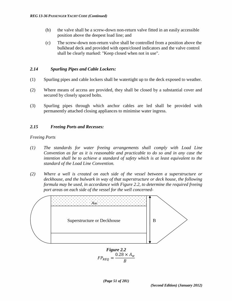
REG 13-36 PASSENGER YACHT CODE (Continued)
(Page 51 of 281)
(Second Edition) (January 2012)
(b) the valve shall be a screw-down non-return valve fitted in an easily accessible
position above the deepest load line; and
(c) The screw-down non-return valve shall be controlled from a position above the
bulkhead deck and provided with open/closed indicators and the valve control
shall be clearly marked: "Keep closed when not in use".
2.14 Spurling Pipes and Cable Lockers:
(1) Spurling pipes and cable lockers shall be watertight up to the deck exposed to weather.
(2) Where means of access are provided, they shall be closed by a substantial cover and
secured by closely spaced bolts.
(3) Spurling pipes through which anchor cables are led shall be provided with
permanently attached closing appliances to minimise water ingress.
2.15 Freeing Ports and Recesses:
Freeing Ports
(1) The standards for water freeing arrangements shall comply with Load Line
Convention as far as it is reasonable and practicable to do so and in any case the
intention shall be to achieve a standard of safety which is at least equivalent to the
standard of the Load Line Convention.
(2) Where a well is created on each side of the vessel between a superstructure or
deckhouse, and the bulwark in way of that superstructure or deck house, the following
formula may be used, in accordance with Figure 2.2, to determine the required freeing
port areas on each side of the vessel for the well concerned-
Figure 2.2
Superstructure or Deckhouse B
Aw

REG 13-36 PASSENGER YACHT CODE (Continued)
(Page 52 of 281)
(Second Edition) (January 2012)
Where- = Required Minimum Freeing Port Area;
Aw = Area of well in way of superstructure; and
B = Maximum beam at deck in way of the well.
(3) In individual cases, when the Administration considers that the requirements of Load
Line Convention with respect to freeing port areas cannot be met, the Administration
may consider and approve alternative arrangements to achieve adequate safety
standards which may take account of a reduced permeability and volume of a well.
(4) For a Passenger Yacht 2 (PY2) the requirement for the minimum freeing port area for
a forward or after well as determined in accordance with paragraph (2) may be
reduced by a form factor equal to the ratio of where-
AW = Actual area of the well;
LW = Overall length of the well;
BW = Maximum breadth of the well; and
Dimensions are measured at half the height of the bulwark above the
deck of the well,
provided that
(a) the maximum reduction shall not exceed 50%;
(b) the stability requirements for the yacht are maintained with all the wells
flooded to any level up to the height of the bulwark; and
(c) the freeing port area provided is sufficient to allow the well to drain in less
than three minutes.
Recesses
(5) Any recess in the weather deck shall be of weathertight construction and shall be self
draining under all normal conditions of heel and trim of the vessel; a swimming pool
or spa bath, open to the elements, shall be treated as a recess.
(6) The means of drainage provided shall be capable of efficient operation when the
vessel is heeled to an angle of 10o.
(7) The drainage arrangements shall have the capability of draining the recess (when
fully charged with water) within 3 minutes when the vessel is upright and at the load
line draft and means shall be provided to prevent the backflow of sea water into the
recess.
(8) Where it is not practical to provide drainage which meets the requirements of
subsections (6) and (7), alternative safety measures may be proposed for approval by
the Administration, provided that where the above requirements for quick drainage

REG 13-36 PASSENGER YACHT CODE (Continued)
(Page 53 of 281)
(Second Edition) (January 2012)
cannot be met, the effect on intact and damage stability shall be considered taking into
account the mass of water and its free surface effect.
2.16 Protection of the Crew:
(1) The deckhouses used for the accommodation of the crew shall be constructed to an
acceptable level of strength.
(2) Guard rails or bulwarks shall be fitted around all exposed decks and the height of the
bulwarks or guard rails shall be at least 1 metre from the deck, provided that where
this height would interfere with the normal operation of the ship, a lesser height may
be approved provided that the Administration is satisfied that adequate protection is
provided;
(3) Guard rails fitted on superstructure and freeboard decks shall have at least three
courses such that the opening below the lowest course of the guard rails shall not
exceed 230 millimetres and the other courses shall be not more than 380 millimetres
apart;
(4) In the case of ships with rounded gunwales the guard rail supports shall be placed on
the flat of the deck.
(5) In other locations, guardrails with at least two courses shall be fitted.
(6) Guard rails shall comply with the following provisions-
(a) fixed, removable or hinged stanchions shall be fitted about 1.5 metres apart
and removable or hinged stanchions shall be capable of being locked in the
upright position;
(b) at least every third stanchion shall be supported by a bracket or stay;
(c) where necessary for the normal operation of the ship, steel wire ropes may be
accepted in lieu of guard rails and such wires shall be made taut by means of
turnbuckles; and
(d) where necessary for the normal operation of the ship, chains fitted between
two fixed stanchions and/or bulwarks are acceptable in lieu of guard rails.
(e) a combination of bulwarks and guardrails shall be permitted providing that
bulwarks comply with applicable freeing port area requirements.
(7) Satisfactory means for safe passage required by (in the form of guard rails, lifelines,
gangways or underdeck passages, etc.) shall be provided for the protection of the crew
in getting to and from their quarters, the machinery space and any other spaces used in
the essential operation of the ship.

REG 13-36 PASSENGER YACHT CODE (Continued)
(Page 54 of 281)
(Second Edition) (January 2012)
This page is intentionally added to achieve correct pagination.

REG 13-36 PASSENGER YACHT CODE (Continued)
(Page 55 of 281)
(Second Edition) (January 2012)
CHAPTER 3
APPLICATION OF OTHER INTERNATIONAL CONVENTIONS AND NATIONAL
LEGISLATION
3.1 Conventions - General:
Every vessel to which this Code applies shall comply with the relevant provisions of other
applicable Conventions (as amended), including but not necessarily limited to the following-
(a) Convention on the International Regulations for Preventing Collisions at Sea,
1972, as amended (COLREG 72);
(b) Convention for the Prevention of Pollution from Ships, 1973, as modified by
the Protocol of 1978 relating thereto, as amended (MARPOL 73/78);
(c) Convention on the Control of Harmful Anti-fouling Systems on Ships, 2001, as
amended (AFS 2001);
(d) Convention for the Control and Management of Ships' Ballast Water and
Sediments, 2004, as amended (BWM 2004);
(e) Convention on Civil Liability for Bunker Oil Pollution Damage, 2001 (bunkers
2001):
(f) relevant Conventions of the International Labour Organization (ILO),
including but not necessarily limited to-
(i) ILO Convention (No. 147) concerning Minimum Standards in Ships
47 and any amendments to or replacements of this Convention;
(ii) Subject to paragraph (g), the Maritime Labour Convention 2006
(MLC 2006), as and when this comes into effect; and
(g) pending the entry into force of the provisions of MLC 2006-
(i) all vessels to which the Code applies shall comply with any MLC
2006 provisions already included in the Code;
(ii) Administrations shall take account of other provisions of MLC
2006 as appropriate, in particular Titles 1, 2 and 4 of the
Convention; and
(iii) Administrations shall also take account of any national legislation
giving effect to the provisions of MLC 2006.

REG 13-36 PASSENGER YACHT CODE (Continued)
(Page 56 of 281)
(Second Edition) (January 2012)
3.2 Navigation Lights:
Navigation lights and shapes shall comply with the applicable provisions of COLREG 72,
including the following provisions-
(a) all navigation lights should be provided with main and emergency power
supply;
(b) all navigation lights required to be shown whilst underway are required to be
duplicated in accordance with IMO Resolution MSC.253(8323
) as may be
amended from time to time; and
(c) approved LED Lights may be used providing the lights meet the technical
specifications of COLREG 72.
3.3 Prevention of Pollution:
Every ship to which this Code applies shall comply with the applicable provisions of the
Annexes to MARPOL 73/78, as amended.
3.4 Anti-Fouling Convention:
(1) This Convention applies to every ship of 400 gross tonnage and above
(2) For EU flagged vessels exceeding 24m in length but less than 400gt REGULATION
(EC) No 782/2003 on the prohibition of organotin compounds on ships states-
"Ships of 24 metres or more in length, but less than 400 gross tonnage, shall carry an
AFS-Declaration to demonstrate compliance."
3.5 Ballast Water Convention:
(1) The Ballast Water Management Convention will probably not enter into force before
the first implementation date for ballast water treatment systems (i.e. 01 January 2009
for ships with a ballast water capacity of less than 5,000m3).
(2) This implies that ships constructed after 01 January 2009 and having ballast capacity
of less than 5000m3
will not have to install treatment systems on these vessels until
their second annual surveys, but not later than 31 December 2011.
23
See MSC.253(83) - Adoption of the Performance Standards for Navigation Lights, Navigation Light
Controllers and Associated Equipment - (Adopted on 8 October 2007).

REG 13-36 PASSENGER YACHT CODE (Continued)
(Page 57 of 281)
(Second Edition) (January 2012)
3.6 Bunkers Convention:
(1) Ships of over 1000 gross tonnage are required to carry an appropriate level of
insurance covering liability for costs arising from pollution damage following a
bunker oil spill from the ship.
(2) As evidence that adequate insurance cover is in place the owner or operator of the
ship is required to carry a Certificate to this effect issued by the Administration.
(3) The Administration will issue such a Bunkers Certificate only where it is satisfied that
the insurance cover provided is acceptable.
3.7 National Legislation:
In applying the provisions of the Code due regard shall be taken of any applicable national
legislation of the Administration concerned.

REG 13-36 PASSENGER YACHT CODE (Continued)
(Page 58 of 281)
(Second Edition) (January 2012)
This page is intentionally added to achieve correct pagination.

REG 13-36 PASSENGER YACHT CODE (Continued)
(Page 59 of 281)
(Second Edition) (January 2012)
CHAPTER 4
CONSTRUCTION, SUBDIVISION AND STABILITY
PART I - GENERAL
4.1 Strength of Ship and Subdivision - General:
(1) The Administration shall satisfy itself that the general structural strength of the ship is
adequate for the draft corresponding to the freeboard assigned.
(2) The ship shall in any case be constructed in accordance with the requirements of
Chapter 2 (Load Lines) and it shall comply with the IMO Intact Stability Code or with
intact stability standards acceptable to the Administration.
(3) Ships shall be as efficiently subdivided as is possible having regard to the nature of
the service for which they are intended and the degree of subdivision shall vary with
the subdivision length (Ls) of the ship and with the service, in such manner that the
highest degree of subdivision corresponds with the ships of greatest subdivision length
(Ls), primarily engaged in the carriage of passengers.
(4) Where it is proposed to fit decks, inner skins or longitudinal bulkheads of sufficient
tightness to seriously restrict the flow of water, the Administration shall be satisfied
that proper consideration is given to beneficial or adverse effects of such structures in
the calculations.
(5) The Table below summarises the stability provisions applicable to the various
categories of Passenger Yacht.
TABLE 4-1 - SUMMARY OF STABILITY REQUIREMENTS
CATEGORY OF
PASSENGER YACHT OPERATIONAL AREA
DAMAGED STABILITY STANDARDS
APPLICABLE ENHANCED
SURVIVABILITY <80 M ≥80 M
Pleasure Vessel not Engaged in Trade
Unlimited
Chapter 4 Part VI
N/A
Chapter 4
Part II N/A
Passenger Yacht Unrestricted (Engaged in Trade)
Unlimited
Chapter 4 Part VI
Chapter 4 Part VII
Chapter 4
Part II Chapter 4 Part VII
PY1 Prescribed International
Voyage
Chapter 4 Part VI
Chapter 4 Part VII.
Chapter 4 Chapter 4 Part VII

REG 13-36 PASSENGER YACHT CODE (Continued)
(Page 60 of 281)
(Second Edition) (January 2012)
CATEGORY OF
PASSENGER YACHT OPERATIONAL AREA
DAMAGED STABILITY STANDARDS
APPLICABLE ENHANCED
SURVIVABILITY <80 M ≥80 M
Part II
PY2
PY 2 Area is within 60 n.m. of a safe haven and not more than 20 n.m. from land in weather conditions not exceeding wind force 6 and sea state 5 on Beaufort scale.
Chapter 4 Part VI
N/A
Chapter 4
Part II
4.2 Application of SOLAS Provisions – General:
(1) Except where provided otherwise in this Chapter, all new vessels to which this Code
applies are required to meet the applicable requirements of the amendments to SOLAS
Chapter II-1 which entered into force on 1 January 2009.
(2) The damage stability requirements in SOLAS Chapter II-1, Parts B-1 through B-4 of
those amendments shall apply to all ships, provided that for vessels up to 80m L (i.e.
Load Line length), the Administration may permit the use of SOLAS 90 Deterministic
methodology, in lieu of sections 4.5 and 4.6, in accordance with Part VI of this
Chapter.

REG 13-36 PASSENGER YACHT CODE (Continued)
(Page 61 of 281)
(Second Edition) (January 2012)
PART II
STABILITY
4.3 Intact Stability and Information24
:
(1) Every ship to which this Code applies shall be inclined upon its completion and the
elements of its stability determined.
(2) Where any alterations are made to a ship so as to materially affect the stability
information supplied to the master-
(a) amended stability information shall be provided;
(b) if necessary the ship shall be re-inclined; and
(c) the ship shall be re-inclined if anticipated deviations exceed one of the values
specified in subsection (3)(b).
(3) At periodical intervals not exceeding five years-
(a) a lightweight survey shall be carried out on all passenger ships to verify any
changes in lightship displacement and longitudinal centre of gravity; and
(b) the ship shall be re-inclined whenever, in comparison with the approved
stability information, a deviation from the lightship displacement exceeding
2% or a deviation of the longitudinal centre of gravity exceeding 1% of Ls is
found or anticipated25
.
(4) Every ship shall be provided with datum draft marks at the bow and stern which are
clearly visible and where these draft marks are not clearly readable, or operational
constraints for a particular trade make it difficult to read the draft marks, then the ship
shall also be fitted with a reliable draught indicating system by which the bow and
stern drafts can be determined.
(5) In applying this section due regard shall be had to the Intact Stability Code as defined
in section 1.3 of this Code and to section 2.3 of this Code.
24
Refer to the Code on Intact Stability for All Types of Ships covered by IMO Instruments, adopted by the
IMO by MSC.267(85). 25
Refer to IMO Circular MSC/Circ.1158 Stability information for passenger ships and cargo ships -
Lightweight check.

REG 13-36 PASSENGER YACHT CODE (Continued)
(Page 62 of 281)
(Second Edition) (January 2012)
4.4 Stability Information to be supplied to the Master26
:
(1) The master shall be supplied with such stability information satisfactory to the
Administration as is necessary to enable him by rapid and simple processes to obtain
accurate guidance as to the stability of the ship under varying conditions of service
and a copy of the stability information shall be furnished to the Administration.
(2) Information shall be provided to the master-
(a) in a form that is approved by the Administration or a recognised organization;
and
(b) such information, and loading information also related to ship strength when
required under subsection (1), shall be carried on board at all times together
with evidence that the information has been approved by the Administration.
(3) The information should include-
(a) curves or tables of minimum operational metacentric height (GM) versus
draught which assures compliance with the relevant intact and damage stability
requirements, alternatively corresponding curves or tables of the maximum
allowable vertical centre of gravity (KG) versus draught, or with the
equivalents of either of these curves;
(b) instructions concerning the operation of cross-flooding arrangements; and
(c) all other data and aids which might be necessary to maintain the required intact
stability and stability after damage.
(4) The stability information shall show the influence of various trims in cases where the
operational trim range exceeds +/- 0.5% of Ls.
(5) For ships which have to fulfil the stability requirements of Part II of this Chapter,
information referred to in subsection (2) is determined from considerations related to
the subdivision index, in the following manner-
(a) minimum required GM (or maximum permissible vertical position of centre of
gravity KG) for the three draughts ds, dp and dl are equal to the GM (or KG
values) of corresponding loading cases used for the calculation of survival
factor si;
(b) for intermediate draughts, values to be used shall be obtained by linear
interpolation applied to the GM value only between the deepest subdivision
draught and the partial subdivision draught and between the partial load line
and the light service draught respectively. Intact stability criteria will also be
taken into account by retaining for each draft the maximum among minimum
26
Refer also to the Guidelines for the preparation of intact stability information (MSC/Circ.456) and the revised guidance to
the master for avoiding dangerous situations in following and quartering seas (MSC.1/Circ.1228).

REG 13-36 PASSENGER YACHT CODE (Continued)
(Page 63 of 281)
(Second Edition) (January 2012)
required GM values or the minimum of maximum permissible KG values for
both criteria; and
(c) if the subdivision index is calculated for different trims, several required GM
curves will be established in the same way.
(6) When curves or tables of minimum operational metacentric height (GM) versus
draught are not appropriate, the master should ensure that the operating condition does
not deviate from a studied loading condition, or verify by calculation that the stability
criteria are satisfied for this loading condition.
(7) In applying this section due regard shall be had to the Intact Stability Code as defined
in section 1.3 of this Code.
4.5 Required Subdivision Index R27
:
(1) The subdivision of a ship is considered sufficient if the attained subdivision index A,
determined in accordance with section 4.6, is not less than the required subdivision
index R calculated in accordance with this regulation and if, in addition, the partial
indices As, Ap and Al are not less than 0.9R for passenger ships.
(2) For all passenger ships to which the damage stability requirements of this Chapter
apply, the degree of subdivision to be provided shall be determined by the required
subdivision index R, as follows-
where:
N = N1 + 2N2;
N1 = number of persons for whom lifeboats are provided28
; and
N2 = number of persons (including officers and crew) the ship is permitted to
carry in excess of N1.
(3) Where the conditions of service are such that compliance with subsection (2) on the
basis of N = N1 + 2N2 is impracticable and where the Administration considers that a
suitably reduced degree of hazard exists29
, a lesser value of N may be taken but in no
case shall the value be less than N = N1 + N2.
27 The Maritime Safety Committee, in adopting the regulations contained in parts B to B-4 of SOLAS, as amended, invited
Administrations to note that the regulations should be applied in conjunction with the explanatory notes developed by the
IMO as set out in Resolution MSC.281(85) in order to ensure their uniform application. 28 Where enhanced survivability is relied upon, N1 shall be deemed to include all persons on board. 29 Regarding the term ―reduced degree of hazard‖, the following interpretation should be applied in accordance with
Regulation 6.2.4 of the above mentioned Resolution MSC.281(85)-
―A lesser value of N, but in no case less than N = N1 + N2, may be allowed at the discretion of the Administration for
passenger ships, which, in the course of their voyages, do not proceed more than 20 miles from the nearest land.‖

REG 13-36 PASSENGER YACHT CODE (Continued)
(Page 64 of 281)
(Second Edition) (January 2012)
4.6 Attained Subdivision Index A:
(1) The attained subdivision index A is obtained by the summation of the partial indices
As, Ap and Al, (weighted as shown) calculated for the draughts ds, dp and dl defined in
section 1.3 in accordance with the following formula-
(2) Each partial index is a summation of contributions from all damage cases taken in
consideration, using the following formula-
where-
i represents each compartment or group of compartments under consideration;
pi accounts for the probability that only the compartment or group of
compartments under consideration may be flooded, disregarding any horizontal
subdivision, as defined in section 4.7; and
si accounts for the probability of survival after flooding the compartment or group
of compartments under consideration, and includes the effect of any horizontal
subdivision, as defined in section 4.8.
(3) In the calculation of A-
(a) the level trim shall be used for the deepest subdivision draught and the partial
subdivision draught;
(b) the actual service trim shall be used for the light service draught; and
(c) if in any service condition, the trim variation in comparison with the calculated
trim is greater than 0.5% of Ls, one or more additional calculations of A are to
be submitted for the same draughts but different trims so that, for all service
conditions, the difference in trim in comparison with the reference trim used
for one calculation will be less than 0.5% of Ls.
(4) When determining the positive righting lever (GZ) of the residual stability curve, the
displacement used should be that of the intact condition; that is, the constant
displacement method of calculation should be used.
(5) The summation indicated by the above formula shall be taken over the ship‘s
subdivision length (Ls) for all cases of flooding in which a single compartment or two
or more adjacent compartments are involved. In the case of unsymmetrical
arrangements, the calculated A value should be the mean value obtained from
calculations involving both sides; alternatively, it should be taken as that
corresponding to the side which evidently gives the least favourable result.

REG 13-36 PASSENGER YACHT CODE (Continued)
(Page 65 of 281)
(Second Edition) (January 2012)
(6) Wherever wing compartments are fitted-
(a) contribution to the summation indicated by the formula shall be taken for all
cases of flooding in which wing compartments are involved;
(b) additionally, cases of simultaneous flooding of a wing compartment or group
of compartments and the adjacent inboard compartment or group of
compartments, but excluding damage of transverse extent greater than one half
of the ship breadth B, may be added; and
(c) for the purpose of this regulation, transverse extent is measured inboard from
ship‘s side, at right angle to the centreline at the level of the deepest
subdivision draught.
(7) In the flooding calculations carried out according to the regulations-
(a) only one breach of the hull and only one free surface need to be assumed; and
(b) the assumed vertical extent of damage is to extend from the baseline upwards
to any watertight horizontal subdivision above the waterline or higher.
provided however, if a lesser extent of damage will give a more severe result, such
extent is to be assumed.
(8) If pipes, ducts or tunnels are situated within the assumed extent of damage,
arrangements are to be made to ensure that progressive flooding cannot thereby extend
to compartments other than those assumed flooded. However, the Administration may
permit minor progressive flooding if it is demonstrated that its effects can be easily
controlled and the safety of the ship is not impaired.
4.7 Calculation of the Factor pi:
(1) The factor pi for a compartment or group of compartments shall be calculated in
accordance with this section using the following notations-
j = the aftmost damage zone number involved in the damage starting with No.1
at the stern;
n = the number of adjacent damage zones involved in the damage;
k = is the number of a particular longitudinal bulkhead as barrier for transverse
penetration in a damage zone counted from shell towards the centre line;
the shell has k = 0;
x1 = the distance from the aft terminal of Ls to the aft end of the zone in
question;
x2 = the distance from the aft terminal of Ls to the forward end of the zone in
question;
b = the mean transverse distance in metres measured at right angles to the
centreline at the deepest subdivision loadline between the shell and an

REG 13-36 PASSENGER YACHT CODE (Continued)
(Page 66 of 281)
(Second Edition) (January 2012)
assumed vertical plane extended between the longitudinal limits used in
calculating the factor pi and which is a tangent to, or common with, all or
part of the outermost portion of the longitudinal bulkhead under
consideration; this vertical plane shall be so orientated that the mean
transverse distance to the shell is a maximum, but not more than twice the
least distance between the plane and the shell; if the upper part of a
longitudinal bulkhead is below the deepest subdivision loadline the vertical
plane used for determination of b is assumed to extend upwards to the
deepest subdivision waterline; in any case, b is not to be taken greater than
B/2.
If the damage involves a single zone only:
pi = p(x1j, x2j)·[r(x1j, x2j, bk) – r(x1j, x2j, bk-1)]
If the damage involves two adjacent zones:
pi = p(x1j, x2j+1)·[r(x1j, x2j+1, bk) – r(x1j, x2j+1, bk-1)]
- p(x1j, x2j)·[r(x1j, x2j, bk) – r(x1j, x2j, bk-1)]
- p(x1j+1, x2j+1)·[r(x1j+1, x2j+1, bk) – r(x1j+1, x2j+1, bk-1)]
If the damage involves three or more adjacent zones:
pi = p(x1j, x2j+n-1)·[r(x1j, x2j+n-1, bk) – r(x1j, x2j+n-1, bk-1)]
- p(x1j, x2j+n-2)·[r(x1j, x2j+n-2, bk) – r(x1j, x2j+n-2, bk-1)]
- p(x1j+1, x2j+n-1)·[r(x1j+1, x2j+n-1, bk) – r(x1j+1, x2j+n-1, bk-1)]
+ p(x1j+1, x2j+n-2)·[r(x1j+1, x2j+n-2, bk) – r(x1j+1, x2j+n-2, bk-1)]
and where r(x1, x2, b0) = 0
(2) The factor p(x1, x2) is to be calculated according to the following formulae-
Overall normalised max damage length: Jmax = 10/33
Knuckle point in the distribution: Jkn = 5/33
Cumulative probability at Jkn: pk = 11/12
Maximum absolute damage length: lmax = 60 metres
Length where normalised distribution ends: L* = 260 metres
Probability density at J = 0:
When Ls ≤ L*:

REG 13-36 PASSENGER YACHT CODE (Continued)
(Page 67 of 281)
(Second Edition) (January 2012)
b12 = b0
When :
The non-dimensional damage length:
The normalised length of a compartment or group of compartments
Jn is to be taken as the lesser of J and Jm
(3) Where neither limit of the compartment or group of compartments under consideration
coincides with the aft or forward terminals-
J≤Jk :

REG 13-36 PASSENGER YACHT CODE (Continued)
(Page 68 of 281)
(Second Edition) (January 2012)
J>Jk:
(4) Where the aft limit of the compartment or group of compartments under consideration
coincides with the aft terminal or the forward limit of the compartment or group of
compartments under consideration coincides with the forward terminal-
J≤Jk:
J>Jk:
(5) Where the compartment or groups of compartments considered extends over the entire
subdivision length (Ls)-
(6) The factor r(x1, x2, b) shall be determined by the following formulae-
where-
; and
(7) Where the compartment or groups of compartments considered extends over the entire
subdivision length (Ls)-

REG 13-36 PASSENGER YACHT CODE (Continued)
(Page 69 of 281)
(Second Edition) (January 2012)
(8) Where neither limits of the compartment or group of compartments under
consideration coincides with the aft or forward terminals-
where-
(9) Where the aft limit of the compartment or group of compartments under consideration
coincides with the aft terminal or the forward limit of the compartment or group of
compartments under consideration coincides with the forward terminal-
4.8 Calculation of the Factor si:
(1) The factor si shall be determined for each case of assumed flooding, involving a
compartment or group of compartments, in accordance with the following notations
and the provisions in this section, where-
θe is the equilibrium heel angle in any stage of flooding, in degrees;
θv is the angle, in any stage of flooding, where the righting lever becomes
negative, or the angle at which an opening incapable of being closed
weathertight becomes submerged;
GZmax is the maximum positive righting lever, in metres, up to the angle θv;
Range is the range of positive righting levers, in degrees, measured from the
angle θe.; the positive range is to be taken up to the angle θv;
Flooding stage is any discrete step during the flooding process, including the
stage before equalisation (if any) until final equilibrium has been reached.
(2) The factor si for any damage case at any initial loading condition, di, shall be obtained
from the formula-
si = minimum { sintermediate,i or sfinal,i smom,i }
where-
sintermediate,i is the probability to survive all intermediate flooding
stages until the final equilibrium stage, and is calculated
in accordance with subsection 3;
sfinal,i is the probability to survive in the final equilibrium stage
of flooding, calculated in accordance with subsection 4;
REG 13-36 PASSENGER YACHT CODE (Continued)
(Page 70 of 281)
(Second Edition) (January 2012)
and
smom,i is the probability to survive heeling moments, and is
calculated in accordance with subsection 5.
(3) The factor s intermediate, i shall be taken as the least of the s-factors obtained from all
flooding stages including the stage before equalisation, if any, and is to be calculated
as follows-
where-
GZmax is not to be taken as more than 0.05 metres and Range as not more than
7°;
sintermediate = 0, if the intermediate heel angle exceeds 15º; and
the time for equalisation shall not exceed 10 minutes where cross-flooding
fittings are required.
(4) The factor sfinal,i shall be obtained from the formula-
where:
GZmax is not to be taken as more than 0.12 metres;
Range is not to be taken as more than 16°;
K = 0 if
otherwise,
and where:
θmin is 7° for passenger ships; and
θmax is 15° for passenger ships.
(5) The factor smom,i shall be calculated at the final equilibrium from the formula-
where:
Displacement is the intact displacement at the subdivision draught;
Mheel is the maximum assumed heeling moment as calculated in accordance
with paragraph 4.1; and
Smom,i ≤ 1.
(6) The heeling moment Mheel is to be calculated as follows-

REG 13-36 PASSENGER YACHT CODE (Continued)
(Page 71 of 281)
(Second Edition) (January 2012)
(7) Mpassenger is the maximum assumed heeling moment resulting from movement of
passengers, and is to be obtained as follows-
(a) by the formula
Mpassenger = (0.075 • Np) • (0.45 • B) (tm)
where-
Np is the maximum number of passengers permitted to be on board in the
service condition corresponding to the deepest subdivision draught under
consideration; and
B is the beam of the ship.
(b) alternatively, the heeling moment may be calculated assuming the passengers
are distributed with 4 persons per square metre on available deck areas towards
one side of the ship on the decks where muster stations are located and in such
a way that they produce the most adverse heeling moment and in doing so, a
weight of 75 kg per passenger is to be assumed.
(8) Mwind is the maximum assumed wind force acting in a damage situation calculated in
accordance with the following formula-
Mwind = (P • A • Z) / 9,806 (tm)
where:
P = 120 N/m2;
A = projected lateral area above waterline;
Z = distance from centre of lateral projected area above waterline to T/2; and
T = ship‘s draught, di.
(9) MSurvivalcraft is the maximum assumed heeling moment due to the launching of all fully
loaded davit-launched survival craft on one side of the ship and it shall be calculated
using the following assumptions-
(a) all lifeboats and rescue boats fitted on the side to which the ship has heeled
after having sustained damage shall be assumed to be swung out fully loaded
and ready for lowering;
(b) for lifeboats which are arranged to be launched fully loaded from the stowed
position, the maximum heeling moment during launching shall be taken;
(c) a fully loaded davit-launched liferaft attached to each davit on the side to
which the ship has heeled after having sustained damage shall be assumed to
be swung out ready for lowering;
(d) persons not in the life-saving appliances which are swung out shall not provide
either additional heeling or righting moment; and
(e) life-saving appliances on the side of the ship opposite to the side to which the
ship has heeled shall be assumed to be in a stowed position.

REG 13-36 PASSENGER YACHT CODE (Continued)
(Page 72 of 281)
(Second Edition) (January 2012)
(10) Unsymmetrical flooding is to be kept to a minimum consistent with the efficient
arrangements in accordance with the following provisions-
(a) where it is necessary to correct large angles of heel, the means adopted shall,
where practicable, be self-acting, but in any case where controls to equalisation
devices are provided they shall be operable from above the bulkhead deck;
(b) these fittings together with their controls shall be acceptable to the
Administration30
and suitable information concerning the use of equalisation
devices shall be supplied to the master of the ship;
(c) tanks and compartments taking part in such equalisation shall be fitted with air
pipes or equivalent means of sufficient cross-section to ensure that the flow of
water into the equalisation compartments is not delayed.
(11) In all cases, si is to be taken as zero in those cases where the final waterline, taking
into account sinkage, heel and trim, immerses-
(a) the lower edge of openings through which progressive flooding may take place
and such flooding is not accounted for in the calculation of factor si; such
openings shall include air-pipes, ventilators and openings which are closed by
means of weathertight doors or hatch covers; and
(b) any part of the bulkhead deck in passenger ships considered a horizontal
evacuation route for compliance with Chapter II-2 of SOLAS as amended.
(12) The factor si is to be taken as zero if, taking into account sinkage, heel and trim, any of
the following occur in any intermediate stage or in the final stage of flooding-
(a) immersion of any vertical escape hatch in the bulkhead deck intended for
compliance with Chapter II-2 of SOLAS as amended;
(b) any controls intended for the operation of watertight doors, equalisation
devices, valves on piping or on ventilation ducts intended to maintain the
integrity of watertight bulkheads from above the bulkhead deck become
inaccessible or inoperable; and
(c) immersion of any part of piping or ventilation ducts carried through a
watertight boundary that is located within any compartment included in
damage cases contributing to the attained index A, if not fitted with watertight
means of closure at each boundary,
provided however that where compartments assumed flooded due to progressive
flooding are taken into account in the damage stability calculations multiple values of
sintermediate,i may be calculated assuming equalisation in additional flooding phases.
(13) Except as provided in section 4.8(12)(a), openings closed by means of watertight
manhole covers and flush scuttles, small watertight hatch covers, remotely operated
30
Reference is made to the Recommendation on a standard method for evaluating cross-flooding arrangements
in passenger ships, adopted by the IMO by Resolution MSC.245(83), as may be amended.

REG 13-36 PASSENGER YACHT CODE (Continued)
(Page 73 of 281)
(Second Edition) (January 2012)
sliding watertight doors, side scuttles of the non-opening type as well as watertight
access doors and hatch covers required to be kept closed at sea need not be
considered.
(14) Where horizontal watertight boundaries are fitted above the waterline under
consideration the s-value calculated for the lower compartment or group of
compartments shall be obtained by multiplying the value as determined in section
4.8(2) by the reduction factor vm according to section 4.8(15), which represents the
probability that the spaces above the horizontal subdivision will not be flooded.
(15) The factor vm shall be obtained from the formula-
where-
Hj, n, m is the least height above the baseline, in metres, within the
longitudinal range of x1(j)...x2(j+n-1) of the mth
horizontal boundary
which is assumed to limit the vertical extent of flooding for the
damaged compartments under consideration;
Hj, n, m-1 is the least height above the baseline, in metres, within the
longitudinal range of x1(j)...x2(j+n-1) of the (m-1)th
horizontal
boundary which is assumed to limit the vertical extent of
flooding for the damaged compartments under consideration;
j signifies the aft terminal of the damaged compartments under
consideration;
m represents each horizontal boundary counted upwards from the
waterline under consideration;
d is the draft in question as defined in section 1.3; and
x1 and x2 represent the terminals of the compartment or group of
compartments considered in section 4.7.
(16) The factors v(Hj, n, m, d) and v(Hj, n, m-1, d) shall be obtained from the formulae-
if is less than, or equal to 7.8 metres;
in all other cases,
where-
v(Hj, n, m, d) is to be taken as 1, if Hm coincides with the uppermost
watertight boundary of the ship within the range
and
v(Hj, n, 0, d) is to be taken as 0;

REG 13-36 PASSENGER YACHT CODE (Continued)
(Page 74 of 281)
(Second Edition) (January 2012)
and in no case is vm to be taken as less than zero or more than 1.
(17) In general, each contribution dA to the index A in the case of horizontal subdivisions is
obtained from the formula-
dA = pi • [ν1 • smin1 + (ν2 — ν1) • smin2 + ....+(1 — νm-1) • smin m]
where
νm the ν-value calculated in accordance with section 4.7(15);
smin the least s-factor for all combinations of damages obtained when
the assumed damage extends from the assumed damage
height Hm downwards.
4.9 Permeability:
(1) For the purpose of the subdivision and damage stability calculations of the regulations,
the permeability of each compartment or part of a compartment shall be as follows-
SPACE PERMEABILITY
Appropriated to stores. 0.60
Occupied by accommodation. 0.95
Occupied by machinery. 0.85
Void spaces. 0.85
Spaces similar to dry cargo spaces
such as storage spaces and the like. 0.95
Intended for liquid. 0 0 or 0.95
(2) Other figures for permeability may be used if substantiated by calculations.
4.10 Requirements Concerning Passenger Ship Stability:
(1) A passenger ship intended to carry 36 or more persons is to be capable of withstanding
damage along the side shell to an extent specified in subsection (2) and compliance
with this section is to be achieved by demonstrating that si, as defined in section
4.8(2), is not less than 0.9 for the three loading conditions on which is based the
calculation of the subdivision index.
(2) The damage extent to be assumed when demonstrating compliance with section
4.10(1), is to be dependent on both N and Ls, as defined in section 1.3 and subsection
4.5(2) respectively, such that-

REG 13-36 PASSENGER YACHT CODE (Continued)
(Page 75 of 281)
(Second Edition) (January 2012)
(a) the vertical extent of damage is to extend from the ship‘s moulded baseline to a
position up to 12.5 metres above the position of the deepest subdivision draft
as defined in section 1.3 unless a lesser vertical extent of damage were to give
a lower value of si, in which case this reduced extent is to be used;
(b) where less than 400 persons are carried, damage length is to be assumed at any
position along the shell side between transverse watertight bulkheads provided
that the distance between two adjacent transverse watertight bulkheads is not
less than the assumed damage length; if the distance between adjacent
transverse watertight bulkheads is less than the assumed damage length, only
one of these bulkheads shall be considered effective for the purpose of
demonstrating compliance with section 4.10(1);
(c) where 36 persons are carried, a damage length of 0.015Ls but not less than 3
metres is to be assumed, in conjunction with a penetration inboard of 0.05B but
not less than 0.75 metres; and
(d) where more than 36, but fewer than 400 persons are carried the values of
damage length and penetration inboard, used in the determination of the
assumed extent of damage, are to be obtained by linear interpolation between
the values of damage length and penetration which apply for ships carrying 36
persons and 400 persons as specified in sections 4.10(2)(d) and 4.10(2)(b).

REG 13-36 PASSENGER YACHT CODE (Continued)
(Page 76 of 281)
(Second Edition) (January 2012)
PART III
SUBDIVISION, WATERTIGHT AND WEATHERTIGHT INTEGRITY
4.11 Double Bottoms:
(1) Subject to paragraphs (a) to (c), a double bottom shall be fitted extending from the
collision bulkhead to the afterpeak bulkhead, as far as this is practicable and
compatible with the design and proper working of the ship-
(a) in ships of 50 metres and upwards but less than 61 m in length a double bottom
shall be fitted at least from the machinery space to the forepeak bulkhead, or
as near thereto as practicable;
(b) in ships of 61 metres and upwards but less than 76 m in length a double bottom
shall be fitted at least outside the machinery space, and shall extend to the fore
and after peak bulkheads, or as near thereto as practicable;
(c) subject to paragraph (c), in ships of 76 metres in length and upwards, a double
bottom shall be fitted amidships, and shall extend to the fore and after peak
bulkheads, or as near thereto as practicable; and
(d) for vessels assessed in accordance with the probabilistic means in accordance
with Parts B-1 through B-4 of SOLAS, where it is deemed that the installation
of a double bottom is impracticable in accordance with paragraph (c), the
vessel must be able to demonstrate compliance with the enhanced survivability
criteria defined in section 4.30 of the Code, following the occurrence of bottom
damage in the area concerned.
(2) Where a double bottom is required to be fitted the inner bottom shall be continued out
to the ship‘s sides in such a manner as to protect the bottom to the turn of the bilge;
such protection will be deemed satisfactory if the inner bottom is not lower at any part
than a plane parallel with the keel line and which is located not less than a vertical
distance h measured from the keel line, as calculated by the formula-
h = B/20,
provided that in no case is the value of h to be less than 760 millimetres and need not
be taken as more than 2,000 millimetres.
(3) Small wells constructed in the double bottom in connection with drainage
arrangements of storage spaces, etc., shall not extend downward more than necessary,
provided that-
(a) a well extending to the outer bottom is, however, permitted at the after end of
the shaft tunnel;

REG 13-36 PASSENGER YACHT CODE (Continued)
(Page 77 of 281)
(Second Edition) (January 2012)
(b) other wells (e.g., for lubricating oil under main engines) may be permitted by
the Administration if satisfied that the arrangements give protection equivalent
to that afforded by a double bottom complying with this regulation; and
(c) in no case shall the vertical distance from the bottom of such a well to a plane
coinciding with the keel line be less than 500 millimetres.
(4) A double bottom need not be fitted in way of watertight tanks, including dry tanks of
moderate size, provided the safety of the ship is not impaired in the event of bottom or
side damage.
(5) Any part of a passenger ship that is not fitted with a double bottom in accordance with
subsections (1) or (4) shall be capable of withstanding bottom damages, as specified in
section 4.11(7), in that part of the ship.
(6) In the case of unusual bottom arrangements in a passenger ship it shall be
demonstrated that the ship is capable of withstanding bottom damages as specified in
section 4.11(7).
(7) Compliance with subsections (5) or (6) is to be achieved by demonstrating that si,
when calculated in accordance with section 4.8 is not less than 1 for all service
conditions when subject to a bottom damage assumed at any position along the ship‘s
bottom in accordance with the following conditions and with an extent specified in
subsection (2) for the affected part of the ship-
(a) Flooding of such spaces shall not render emergency power and lighting,
internal communication, signals or other emergency devices inoperable in
other parts of the ship.
(b) Assumed extent of damage shall be as follows-
Extent For 0.3 L from the forward
perpendicular of the ship Any other part of the ship
Longitudinal
extent
1/3 L2/3
or 14.5 metres,
whichever is less
1/3 L2/3
or 14.5 metres,
whichever is less
Transverse extent B/6 or 10 metres, whichever is
less
B/6 or 5 metres, whichever
is less
Vertical extent,
measured from
the keel line
B/20 or 2 metres, whichever is
less
B/20 or 2 metres,
whichever is less
(c) If any damage of a lesser extent than the maximum damage specified in section
4.11(7)(b) would result in a more severe condition, such damage should be
considered.
(8) In case of large lower compartments in passenger ships-
(a) the Administration may require an increased double bottom height of not more
than B/10 or 3 metres, whichever is less, measured from the keel line;

REG 13-36 PASSENGER YACHT CODE (Continued)
(Page 78 of 281)
(Second Edition) (January 2012)
(b) alternatively, bottom damages may be calculated for these areas, in accordance
with subsection (7), but assuming an increased vertical extent.
4.12 Construction of Watertight Bulkheads:
(1) Each watertight subdivision bulkhead, whether transverse or longitudinal, shall be
constructed having scantlings as specified in section 1.3, in the definition for
―watertight‖, and in all cases, watertight subdivision bulkheads shall be capable of
supporting at least the pressure due to a head of water up to the bulkhead deck.
(2) Steps and recesses in watertight bulkheads shall be as strong as the bulkhead at the
place where each occurs.
4.13 Initial Testing of Watertight Bulkheads, etc.:
(1) Testing of watertight spaces not intended to hold by filling them with water is not
compulsory but where such testing is not carried out-
(a) a hose test shall be carried out where practicable;
(b) this test shall be carried out in the most advanced stage of the fitting out of the
ship;
(c) where a hose test is not practicable because of possible damage to machinery,
electrical equipment insulation or outfitting items, it may be replaced by a
careful visual examination of welded connections, supported where deemed
necessary by means such as a dye penetrant test or an ultrasonic leak test or an
equivalent test; and
(d) in any case a thorough inspection of the watertight bulkheads shall be carried
out.
(2) The forepeak, double bottom (including duct keels) and inner skins shall be tested
with water to a head corresponding to the requirements of section 4.12(1).
(3) Tanks which are intended to hold liquids, and which form part of the watertight
subdivision of the ship, shall be tested for tightness and structural strength with water
to a head corresponding to its design pressure and the water head is in no case to be
less than the top of the air pipes or to a level of 2.4 metres above the top of the tank,
whichever is the greater.
(4) The tests referred to in subsections (2) and (3) are for the purpose of ensuring that the
subdivision structural arrangements are watertight and are not to be regarded as a test
of the fitness of any compartment for the storage of oil fuel or for other special
purposes for which a test of a superior character may be required depending on the
height to which the liquid has access in the tank or its connections.

REG 13-36 PASSENGER YACHT CODE (Continued)
(Page 79 of 281)
(Second Edition) (January 2012)
4.14 Peak and Machinery Space Bulkheads, Shaft Tunnels, etc.:
(1) A collision bulkhead shall be fitted which shall be watertight up to the bulkhead deck
and this bulkhead shall be located at a distance from the forward perpendicular of not
less than 0.05L or 10 metres, whichever is the less, and, except as may be permitted by
the Administration, not more than 0.08L or 0.05L + 3 metres, whichever is the greater.
(2) Where any part of the ship below the waterline extends forward of the forward
perpendicular, e.g., a bulbous bow, the distances stipulated in subsection (1) shall be
measured from a point either-
(a) at the mid-length of such extension;
(b) at a distance 0.015L forward of the forward perpendicular; or
(c) at a distance 3 metres forward of the forward perpendicular,
whichever gives the smallest measurement.
(3) The bulkhead may have steps or recesses provided they are within the limits
prescribed in subsections (1) or (2).
(4) No doors, manholes, access openings, ventilation ducts or any other openings shall be
fitted in the collision bulkhead below the bulkhead deck.
(5) The collision bulkhead shall comply with the following provisions-
(a) except as provided in paragraph (b), the collision bulkhead may be pierced
below the bulkhead deck by not more than one pipe for dealing with fluid in
the forepeak tank, provided that the pipe is fitted with a screw-down valve
capable of being operated from above the bulkhead deck, the valve chest being
secured inside the forepeak to the collision bulkhead, provided that-
(i) the Administration may, however, authorise the fitting of this valve
on the after side of the collision bulkhead where that the valve is
readily accessible under all service conditions and the space in
which it is located is not a storage space;
(ii) all valves shall be of steel, bronze or other approved ductile
material; and
(iii) valves of ordinary cast iron or similar material are not acceptable.
(b) If the forepeak is divided to hold two different kinds of liquids the
Administration may allow the collision bulkhead to be pierced below the
bulkhead deck by two pipes, each of which is fitted as required by paragraph
(a), provided the Administration is satisfied that there is no practical alternative
to the fitting of such a second pipe and that, having regard to the additional
subdivision provided in the forepeak, the safety of the ship is maintained.
(6) Where a long forward superstructure is fitted-

REG 13-36 PASSENGER YACHT CODE (Continued)
(Page 80 of 281)
(Second Edition) (January 2012)
(a) the collision bulkhead shall be extended weathertight to the deck next above
the bulkhead deck;
(b) the extension need not be fitted directly above the bulkhead below provided it
is located within the limits prescribed in subsection (1) or (2) and that the part
of the deck which forms the step is made effectively weathertight; and
(7) The number of openings in the extension of the collision bulkhead above the freeboard
deck shall be restricted to the minimum compatible with the design and normal
operation of the ship and all such openings shall be capable of being closed
weathertight.
(8) Bulkheads shall be fitted separating the machinery space accommodation spaces
forward and aft and made watertight up to the bulkhead deck and in passenger ships an
afterpeak bulkhead shall also be fitted and made watertight up to the bulkhead deck,
provided that the afterpeak bulkhead may, however, be stepped below the bulkhead
deck, providing the degree of safety of the ship as regards subdivision is not thereby
diminished.
(9) In all cases stern tubes shall be enclosed in watertight spaces of moderate volume and
the stern gland shall be situated in a watertight shaft tunnel or other watertight space
separate from the stern tube compartment and of such volume that, if flooded by
leakage through the stern gland, the bulkhead deck will not be immersed.
4.15 Openings in Watertight Bulkheads below the Bulkhead Deck:
(1) The number of openings in watertight bulkheads shall be reduced to the minimum
compatible with the design and proper working of the ship, satisfactory means shall be
provided for closing these openings.
(2) Watertight bulkhead integrity shall be maintained in accordance with the following
provisions-
(a) where pipes, scuppers, electric cables, etc., are carried through watertight
bulkheads, arrangements shall be made to ensure the watertight integrity of the
bulkheads;
(b) valves not forming part of a piping system shall not be permitted in watertight
bulkheads; and
(c) lead or other heat sensitive materials shall not be used in systems which
penetrate watertight bulkheads, where deterioration of such systems in the
event of fire would impair the watertight integrity of the bulkheads.
(3) No doors, manholes, or access openings are permitted in watertight transverse
bulkheads dividing a storage space from an adjoining storage space, except as
provided in section 4.15(9).

REG 13-36 PASSENGER YACHT CODE (Continued)
(Page 81 of 281)
(Second Edition) (January 2012)
(4) Subject to section 4.15(10)-
(a) not more than one door, apart from the doors to shaft tunnels, may be fitted in
each watertight bulkhead within spaces containing the main and auxiliary
propulsion machinery including boilers serving the needs of propulsion;
(b) where two or more shafts are fitted, the tunnels shall be connected by an
intercommunicating passage;
(c) there shall be only one door between the machinery space and the tunnel
spaces where two shafts are fitted and only two doors where there are more
than two shafts;
(d) all these doors shall be of the sliding type and shall be so located as to have
their sills as high as practicable; and
(e) the hand gear for operating these doors from above the bulkhead deck shall be
situated outside the spaces containing the machinery.
(5) Watertight doors shall comply with the following general provisions-
(a) watertight doors, except as provided in section 4.15(9), shall be power-
operated sliding doors complying with the requirements of section 4.15(7)
capable of being closed simultaneously from the central operating console at
the navigation bridge in not more than 60 seconds with the ship in the upright
position; and
(b) the means of operation whether by power or by hand of any power-operated
sliding watertight door shall be capable of closing the door with the ship listed
to 15° either way and consideration shall also be given to the forces which may
act on either side of the door as may be experienced when water is flowing
through the opening applying a static head equivalent to a water height of at
least 1 metre above the sill on the centreline of the door;
(c) watertight doors and their controls, including hydraulic piping and electric
cables shall comply with the following provisions
(i) the controls shall be kept as close as practicable to the bulkhead in
which the doors are fitted, in order to minimise the likelihood of
them being involved in any damage which the ship may sustain;
and
(ii) the positioning of watertight doors and their controls shall be such
that if the ship sustains damage within one fifth of the breadth of
the ship, as defined in section 1.3 such distance being measured at
right angles to the centreline at the level of the deepest subdivision
draught, the operation of the watertight doors clear of the damaged
portion of the ship is not impaired.
(6) All power-operated sliding watertight doors shall-
(a) be provided with means of indication which will show at all remote operating
positions whether the doors are open or closed; and

REG 13-36 PASSENGER YACHT CODE (Continued)
(Page 82 of 281)
(Second Edition) (January 2012)
(b) have their remote operating positions only at the navigation bridge as required
by section 4.15(7)(a)(v) and at the location where hand operation above the
bulkhead deck is required by section 4.15(7)(a)(iv).
(7) Watertight doors shall comply with the following provisions-
(a) Each power-operated sliding watertight door shall-
(i) have a vertical or horizontal motion;
(ii) subject to section 4.15(10), be normally limited to a maximum clear
opening width of 1.2 metres; provided that the Administration may
permit larger doors only to the extent considered necessary for the
effective operation of the ship provided that other safety measures,
including the following, are taken into consideration-
(ba) special consideration shall be given to the strength of the
door and its closing appliances in order to prevent leakages;
and
(bb) the door shall be located inboard the damage zone B/5;
(iii) be fitted with the necessary equipment to open and close the door
using electric power, hydraulic power, or any other form of power
that is acceptable to the Administration;
(iv) be provided with an individual hand-operated mechanism such that
it shall be possible to open and close the door by hand at the door
itself from either side, and in addition, close the door from an
accessible position above the bulkhead deck with an all round crank
motion or some other movement providing the same degree of
safety acceptable to the Administration and the direction of rotation
or other movement is to be clearly indicated at all operating
positions; the time necessary for the complete closure of the door,
when operating by hand gear, shall not exceed 90 seconds with the
ship in the upright position;
(v) be provided with controls for opening and closing the door by
power from both sides of the door and also for closing the door by
power from the central operating console at the navigation bridge;
(vi) be provided with an audible alarm in accordance with the following
provisions-
(ba) it shall be distinct from any other alarm in the area;
(bb) it shall sound whenever the door is closed remotely by
power and shall sound for at least 5 seconds but no more
than 10 seconds before the door begins to move and shall
continue sounding until the door is completely closed;
provided that in the case of remote hand operation it is
sufficient for the audible alarm to sound only when the door
is moving; and

REG 13-36 PASSENGER YACHT CODE (Continued)
(Page 83 of 281)
(Second Edition) (January 2012)
(bc) additionally, in passenger areas and areas of high ambient
noise the Administration may require the audible alarm to
be supplemented by an intermittent visual signal at the door;
(vii) have an approximately uniform rate of closure under power and the
closure time, from the time the door begins to move to the time it
reaches the completely closed position shall in no case be less than
20 seconds or more than 40 seconds with the ship in the upright
position;
(b) The electrical power required for-
(i) power-operated sliding watertight doors shall be supplied from the
emergency switchboard either directly or by a dedicated
distribution board situated above the bulkhead deck;
(ii) the associated control, indication and alarm circuits shall be
supplied from the emergency switchboard either directly or by a
dedicated distribution board situated above the bulkhead deck and
be capable of being automatically supplied by the transitional
source of emergency electrical power required by Regulation 42 of
Chapter II-1 D of SOLAS, in accordance with Chapter 5 of this
Code, in the event of failure of either the main or emergency source
of electrical power.
(c) Power-operated sliding watertight doors shall have either-
(i) a centralised hydraulic system complying with the following
provisions-
(ba) two independent power sources each consisting of a motor
and pump capable of simultaneously closing all doors;
(bb) having, for the whole installation, hydraulic accumulators of
sufficient capacity to operate all the doors at least three
times, i.e. closed-open-closed, against an adverse list of 15º;
(bc) the operating cycle referred to in sub-subparagraph (bb)
above shall be capable of being carried out when the
accumulator is at the pump cut-in pressure;
(bd) the fluid used in the system shall be chosen considering the
temperatures liable to be encountered by the installation
during its service;
(be) the power operating system shall be designed to minimise
the possibility of having a single failure in the hydraulic
piping adversely affect the operation of more than one door;
(bf) the hydraulic system shall be provided with a low-level
alarm for hydraulic fluid reservoirs serving the power-
operated system and a low gas pressure alarm or other

REG 13-36 PASSENGER YACHT CODE (Continued)
(Page 84 of 281)
(Second Edition) (January 2012)
effective means of monitoring loss of stored energy in
hydraulic accumulators; and
(bg) the alarm referred to in sub-subparagraph (bf) above is to be
audible and visual and shall be situated on the central
operating console at the navigation bridge;
OR
(ii) an independent hydraulic system for each door complying with the
following provisions-
(ba) each power source shall consist of a motor and pump
capable of opening and closing the door;
(bb) in addition, there shall be a hydraulic accumulator of
sufficient capacity to operate the door at least three times,
i.e. closed-open-closed, against an adverse list of 15º and
this operating cycle shall be capable of being carried out
when the accumulator is at the pump cut-in pressure;
(bc) the fluid used shall be chosen considering the temperatures
liable to be encountered by the installation during its
service;
(bd) a low gas pressure group alarm or other effective means of
monitoring loss of stored energy in hydraulic accumulators
shall be provided at the central operating console on the
navigation bridge; and
(be) loss of stored energy indication at each local operating
position shall also be provided;
OR
(iii) an independent electrical system and motor for each door
complying with the following provisions-
(ba) each power source shall consist of a motor capable of
opening and closing the door;
(bb) the power source shall be capable of being automatically
supplied by the transitional source of emergency electrical
power as required by Regulation 42 of Chapter II-1 D of
SOLAS, in accordance with Chapter 5 of this Code, in the
event of failure of either the main or emergency source of
electrical power and with sufficient capacity to operate the
door at least three times, i.e. closed-open-closed, against an
adverse list of 15º,
(iv) For the systems specified in sections 4.15(7)(c)(i), 4.15(7)(c)((ii)
and 4.15(7)(c)(iii), provision should be made as follows-

REG 13-36 PASSENGER YACHT CODE (Continued)
(Page 85 of 281)
(Second Edition) (January 2012)
(ba) power systems for power-operated watertight sliding doors
shall be separate from any other power system; and
(bb) a single failure in the electric or hydraulic power-operated
systems excluding the hydraulic actuator shall not prevent
the hand operation of any door.
(d) control handles shall be provided at each side of the bulkhead at a minimum
height of 1.6 metres above the floor and shall be so arranged as to enable
persons passing through the doorway to hold both handles in the open position
without being able to set the power closing mechanism in operation
accidentally and the direction of movement of the handles in opening and
closing the door shall be in the direction of door movement and shall be clearly
indicated
(e) as far as practicable, electrical equipment and components for watertight doors
shall be situated above the bulkhead deck and outside hazardous areas and
spaces.
(f) the enclosures of electrical components necessarily situated below the
bulkhead deck shall provide suitable protection against the ingress of water31
.
(g) electric power, control, indication and alarm circuits shall be protected against
fault in such a way that a failure in one door circuit will not cause a failure in
any other door circuit. Short circuits or other faults in the alarm or indicator
circuits of a door shall not result in a loss of power operation of that door and
arrangements shall be such that leakage of water into the electrical equipment
located below the bulkhead deck will not cause the door to open.
(h) the power operating or control system of a power-operated sliding watertight
door shall comply with the following provisions-
(i) a single electrical failure in the power operating or control system
of a power-operated sliding watertight door shall not result in a
closed door opening;
(ii) the availability of the power supply should be continuously
monitored at a point in the electrical circuit as near as practicable to
each of the motors required by section 4.15(7); and
(iii) the loss of any such power supply should activate an audible and
visual alarm at the central operating console at the navigation
bridge.
31
Refer to the following publication IEC 60529-(2003)-
(a) electrical motors, associated circuits and control components; protected to IPX 7 standard;
(b) door position indicators and associated circuit components; protected to IPX 8 standard; and
(c) door movement warning signals; protected to IPX 6 standard.
Other arrangements for the enclosures of electrical components may be fitted provided the Administration is
satisfied that an equivalent protection is achieved. The water pressure IPX 8 shall be based on the pressure that
may occur at the location of the component during flooding for a period of 36 hours.

REG 13-36 PASSENGER YACHT CODE (Continued)
(Page 86 of 281)
(Second Edition) (January 2012)
(8) The central operating console at the navigation bridge shall comply with the following
provisions-
(a) it shall have a "master mode" switch with two modes of control as follows-
(i) a "local control" mode which shall allow any door to be locally
opened and locally closed after use without automatic closure; and
(ii) a "doors closed" mode which shall automatically close any door
that is open;
(b) the "doors closed" mode shall-automatically close any door that is open and
permit doors to be opened locally and shall automatically re-close the doors
upon release of the local control mechanism.
(c) the "master mode" switch shall normally be in the "local control" mode.
(d) the "doors closed" mode shall only be used in an emergency or for testing
purposes; and
(e) special consideration shall be given to the reliability of the "master mode"
switch.
(f) the console shall be-
(i) be provided with a diagram showing the location of each door, with
visual indicators to show whether each door is open or closed;
(ii) be fitted with a red light indicating that a door is fully open and a
green light indicating that door is fully closed and when a door is
closed remotely the red indicating light shall indicate the
intermediate position by flashing,
(g) the indicating circuit shall be independent of the control circuit for each door;
and
(h) it shall not be possible to remotely open any door from the central operating
console.
(9) If the Administration is satisfied that the fitting of watertight doors in watertight
bulkheads dividing storage between deck spaces is essential then such doors, of
satisfactory construction, may be fitted in accordance with the following provisions-
(a) such doors may be hinged, rolling or sliding doors but shall not be remotely
controlled;
(b) they shall be fitted at the highest level and as far from the shell plating as
practicable, but in no case shall the outboard vertical edges be situated at a
distance from the shell plating which is less than one fifth of the breadth of the
ship, as defined in section 1.3, such distance being measured at right angles to
the centreline at the level of the deepest subdivision draught;
(c) should any such doors be accessible during the voyage, they shall be fitted
with a device which prevents unauthorised opening; and

REG 13-36 PASSENGER YACHT CODE (Continued)
(Page 87 of 281)
(Second Edition) (January 2012)
(d) when it is proposed to fit such doors, the number and arrangements shall
receive the special consideration of the Administration.
(10) Portable plates on bulkheads shall not be permitted except in machinery spaces and
where they are permitted shall be subject to the following conditions-
(a) the Administration may permit not more than one power-operated sliding
watertight door in each watertight bulkhead larger than those specified in
section 4.15(7)(a)(ii) to be substituted for these portable plates, provided these
doors are intended to remain closed during navigation except in case of urgent
necessity at the discretion of the master; and
(b) such doors need not meet the requirements of section 4.15(7)(a)(iv) regarding
complete closure by hand-operated gear in 90 seconds.
(11) Where trunkways or tunnels for access from crew accommodation to other spaces, for
piping, or for any other purpose are carried through watertight bulkheads, they shall be
comply with the following provisions-
(a) they shall watertight and in accordance with the requirements of section 4.18;
(b) the access to at least one end of each such tunnel or trunkway, if used as a
passage at sea, shall be through a trunk extending watertight to a height
sufficient to permit access above the bulkhead deck;
(c) the access to the other end of the trunkway or tunnel may be through a
watertight door of the type required by its location in the ship;
(d) such trunkways or tunnels shall not extend through the first subdivision
bulkhead abaft the collision bulkhead;
(e) where it is proposed to fit tunnels piercing watertight bulkheads, these shall
receive the special consideration of the Administration; and
(f) where trunkways in connection with refrigerated spaces and ventilation or
forced draught trunks are carried through more than one watertight bulkhead,
the means of closure at such openings shall be operated by power and be
capable of being closed from a central position situated above the bulkhead
deck.
4.16 Openings in the Shell Plating below the Bulkhead Deck:
(1) The number of openings in the shell plating shall be reduced to the minimum
compatible with the design and proper working of the ship.
(2) The arrangement and efficiency of the means for closing any opening in the shell
plating shall be consistent with its intended purpose and the position in which it is
fitted and generally to the satisfaction of the Administration.

REG 13-36 PASSENGER YACHT CODE (Continued)
(Page 88 of 281)
(Second Edition) (January 2012)
(3) Subject to the requirements of Chapter 2, no sidescuttle or window shall be fitted in
such a position that its sill is below a line drawn parallel to the bulkhead deck at side
and having its lowest point 2.5% of the breadth of the ship above the deepest
subdivision load line, or 500 millimetres, whichever is the greater.
(4) All sidescuttles the sills of which are below the bulkhead deck, as permitted by
subsection (3) shall be such of construction, and subject to strict procedures, as will
effectively prevent any person opening them without the sanction of the master.
(5) Efficient inside deadlights so arranged that they can be easily and effectively closed
and secured watertight, shall be fitted to all sidescuttles and windows located below
the margin line. Portable deadlights shall be stowed adjacent to the sidescuttles and
windows they serve.
(6) The number of scuppers, sanitary discharges and other similar openings in the shell
plating shall be reduced to the minimum either by making each discharge serve for as
many as possible of the sanitary and other pipes, or in any other satisfactory manner.
(7) All inlets and discharges in the shell plating shall be fitted with efficient and
accessible arrangements for preventing the accidental admission of water into the ship.
(8) Subject to the requirements of the International Convention on Load Lines in force,
and except as provided in subsection (10), each separate discharge led through the
shell plating from spaces below the margin line shall comply with the following
provisions-
(a) the discharge shall be provided with either one automatic non-return valve
fitted with a positive means of closing it from above the bulkhead deck or with
two automatic non-return valves without positive means of closing, provided
that the inboard valve is situated above the deepest subdivision load line and is
always accessible for examination under service conditions; and
(b) where a valve with positive means of closing is fitted, the operating position
above the bulkhead deck shall always be readily accessible and means shall be
provided for indicating whether the valve is open or closed.
(9) The requirements of the International Convention on Load Lines shall apply to
discharges led through the shell plating from spaces above the margin line.
(10) Machinery room main and auxiliary sea inlets and discharges in connection with the
operation of machinery shall be fitted with readily accessible valves between the pipes
and the shell plating or between the pipes and fabricated boxes attached to the shell
plating and the valves shall be provided with indicators showing whether they are open
or closed and additionally be capable of operation from above the freeboard deck:
provided that in continuously Manned Machinery Spaces the valves may be controlled
locally but they shall also be provided with indicators showing whether they are open or
closed.

REG 13-36 PASSENGER YACHT CODE (Continued)
(Page 89 of 281)
(Second Edition) (January 2012)
(11) All shell fittings, valves and pipes required by this Chapter comply with the following
provisions-
(a) shell fittings and valves shall be of steel, bronze or other approved ductile
material;
(b) valves of ordinary cast iron or similar material are not acceptable;
(c) pipes shall be of steel or other equivalent material to the satisfaction of the
Administration.
(12) Ports fitted below the margin line shall be of sufficient strength and shall be effectively
closed and secured watertight before the ship leaves port, and shall be kept closed
during navigation.
(13) Such ports shall in no case be so fitted as to have their lowest point below the deepest
subdivision load line.
(14) The inboard opening of each ash-chute, rubbish-chute, etc., shall be fitted with an
efficient cover.
(15) If the inboard opening is situated below the margin line, the cover shall be watertight,
and in addition an automatic non-return valve shall be fitted in the chute in an easily
accessible position above the deepest subdivision load line and when the chute is not
in use both the cover and the valve shall be kept closed and secured.
(16) In applying this section due regard shall also be had to section 2.13 of the Code.
4.17 Construction and Initial Testing of Watertight Doors, Sidescuttles, etc.:
(1) In all ships-
(a) the design, materials and construction of all watertight doors, sidescuttles,
gangway and stores loading ports, valves, pipes, and rubbish-chutes referred to
in these regulations shall be to the satisfaction of the Administration;
(b) such valves, doors and mechanisms shall be suitably marked to ensure that
they may be properly used to provide maximum safety; and
(c) the frames of vertical watertight doors shall have no groove at the bottom in
which dirt might lodge and prevent the door closing properly.
(2) In all ships-
(a) watertight doors shall be tested by water pressure to a head of water they might
sustain in a final or intermediate stage of flooding;
(b) where testing of individual doors is not carried out because of possible damage
to insulation or outfitting items, testing of individual doors may be replaced by
a prototype pressure test of each type and size of door with a test pressure
REG 13-36 PASSENGER YACHT CODE (Continued)
(Page 90 of 281)
(Second Edition) (January 2012)
corresponding at least to the head required for the intended location provided
that-
(i) the prototype test shall be carried out before the door is fitted;
(ii) the installation method and procedure for fitting the door on board
shall correspond to that of the prototype test; and
(iii) when fitted on board, each door shall be checked for proper seating
between the bulkhead, the frame and the door.
4.18 Construction and Initial Testing of Watertight Decks, Trunks, etc.:
(1) Watertight decks, trunks, tunnels, duct keels and ventilators shall-
(a) be of the same strength as watertight bulkheads at corresponding levels and the
means used for making them watertight, and the arrangements adopted for
closing openings in them, shall be to the satisfaction of the Administration;
(b) watertight ventilators and trunks shall be carried at least up to the bulkhead
deck;
(2) where a ventilation trunk passing through a structure penetrates the bulkhead deck, the
trunk shall be capable of withstanding the water pressure that may be present within
the trunk, after having taken into account the maximum heel angle allowable during
intermediate stages of flooding, in accordance with section 4.8.
(3) after completion, a hose or flooding test shall be applied to watertight decks and a
hose test to watertight trunks, tunnels and ventilators.
4.19 Internal Watertight Integrity above the Bulkhead Deck:
(1) The Administration may require that all reasonable and practicable measures shall be
taken to limit the entry and spread of water above the bulkhead deck in accordance
with the following provisions-
(a) such measures may include partial bulkheads or webs;
(b) when partial watertight bulkheads and webs are fitted on the bulkhead deck,
above or in the immediate vicinity of watertight bulkheads, they shall have
watertight shell and bulkhead deck connections so as to restrict the flow of
water along the deck when the ship is in a heeled damaged condition;
(c) where the partial watertight bulkhead does not line up with the bulkhead
below, the bulkhead deck between shall be made effectively watertight; and
(d) where openings, pipes, scuppers, electric cables etc. are carried through the
partial watertight bulkheads or decks within the immersed part of the bulkhead

REG 13-36 PASSENGER YACHT CODE (Continued)
(Page 91 of 281)
(Second Edition) (January 2012)
deck, arrangements shall be made to ensure the watertight integrity of the
structure above the bulkhead deck32
.
(2) All openings in the exposed weather deck shall have coamings of ample height and
strength and shall be provided with efficient means for expeditiously closing them
weathertight. Freeing ports, open rails and scuppers shall be fitted as necessary for
rapidly clearing the weather deck of water under all weather conditions.
(3) The open end of air pipes terminating within a superstructure shall-
(a) be at least 1 metre above the waterline when the ship heels to an angle of 15º,
or the maximum angle of heel during intermediate stages of flooding, as
determined by direct calculation, whichever is the greater;
(b) alternatively, air pipes from tanks other than oil tanks may discharge through
the side of the superstructure; and
(c) the provisions of this paragraph are without prejudice to the provisions of the
International Convention on Load Lines in force.
(4) Sidescuttles, gangway, stores loading and fuelling ports and other means for closing
openings in the shell plating above the bulkhead deck shall be of efficient design and
construction and of sufficient strength having regard to the spaces in which they are
fitted and their positions relative to the deepest subdivision draught.
(5) Efficient inside deadlights, so arranged that they can be easily and effectively closed
and secured watertight, shall be provided for all sidescuttles to spaces below the first
deck above the bulkhead deck.
(6) In applying the provisions of this section due regard shall be had to section 2.12 of
Chapter 2.
32
Refer to the Guidance notes on the integrity of flooding boundaries above the bulkhead deck of passenger
ships for proper application of regulations II-1/8 and 20, paragraph 1, of SOLAS 1974, as amended
(MSC/Circ.541, as may be amended).
REG 13-36 PASSENGER YACHT CODE (Continued)
(Page 92 of 281)
(Second Edition) (January 2012)
PART IV
SUBDIVISION LOADLINE ASSIGNMENT
4.20 Assigning, Marking and Recording of Subdivision Load Lines:
(1) In order that the required degree of subdivision shall be maintained a load line
corresponding to the approved subdivision draught shall be assigned and marked on
the ship‘s sides;
(2) Subject to subsection (3), the subdivision load lines assigned and marked shall be
recorded in the Passenger Ship Safety Certificate, and shall be distinguished by the
notation P1 for the principal passenger service configuration, and P2, P3, etc., for the
alternative configurations and the principal passenger configuration shall be taken as
the mode of operation in which the required subdivision index R will have the
highest value.
(3) Where assessed using the deterministic means in accordance with Part VI of this
Chapter, the subdivision load lines assigned and marked shall be recorded in the
Passenger Ship Safety Certificate and shall be distinguished by the notation C.1 for
the principal passenger condition and C.2, C.3, etc., for the alternative conditions.
(4) The freeboard corresponding to each of these load lines shall be measured at the
same position and from the same deck line as the freeboards determined in
accordance with the International Convention on Load Lines in force. (See also
section 2.3 and 2.4 of Chapter 2 of the Code.)
(5) The freeboard corresponding to each approved subdivision load line and the service
configuration, for which it is approved, shall be clearly indicated on the Passenger
Ship Safety Certificate.
(6) In no case shall any subdivision load line mark be placed above the deepest load line
in salt water as determined by the strength of the ship or the International
Convention on Load Lines in force.
(7) Whatever may be the position of the subdivision load line marks, a ship shall in no
case be loaded so as to submerge the load line mark appropriate to the season and
locality as determined in accordance with the International Convention on Load
Lines in force.
(8) A ship shall in no case be so loaded that when it is in salt water the subdivision load
line mark appropriate to the particular voyage and service configuration is
submerged.

REG 13-36 PASSENGER YACHT CODE (Continued)
(Page 93 of 281)
(Second Edition) (January 2012)
PART V
STABILITY MANAGEMENT
4.21 Damage Control Information: 33
(1) There shall be permanently exhibited, or readily available on the navigation bridge,
for the guidance of the officer in charge of the ship-
(a) plans showing clearly for each deck and storage space the boundaries of the
watertight compartments, the openings therein with the means of closure and
position of any controls thereof, and the arrangements for the correction of
any list due to flooding;
(b) booklets containing the aforementioned information shall be made available
to the officers of the ship.
(2) Watertight doors in passenger ships permitted to remain open during navigation shall
be clearly indicated in the ship‘s stability information.
(3) General precautions to be included shall consist of a listing of equipment, conditions,
and operational procedures, considered by the Administration to be necessary to
maintain watertight integrity under normal ship operations.
(4) Specific precautions to be included shall consist of a listing of elements (i.e.
closures, security of stores, sounding of alarms, etc.) considered by the
Administration to be vital to the survival of the ship, passengers and crew.
(5) In case of ships to which damage stability requirements of Part II of this Chapter
apply, damage stability information shall provide the master with a simple and easily
understandable way of assessing the ship‘s survivability in all damage cases
involving a compartment or group of compartments.
4.22 Loading of Passenger Ships:
(1) On completion of loading of the ship-
(a) the master shall, prior to the ship‘s departure, determine the ship‘s trim and
stability and also ascertain and record that the ship is in compliance with
stability criteria in relevant regulations; and
(b) the determination of the ship‘s stability shall always be made by calculation
provided that the Administration may accept the use of an electronic loading
and stability computer or equivalent means for this purpose.
33 Refer to the Guidelines for damage control plans contained in MSC.1/Circular.1245 - Guidelines for Damage Control
Plans and Information to the Master (as may be amended from time to time)

REG 13-36 PASSENGER YACHT CODE (Continued)
(Page 94 of 281)
(Second Edition) (January 2012)
(2) Water ballast should not in general be carried in tanks intended for oil fuel provided
that in ships in which it is not practicable to avoid putting water in oil fuel tanks, oily-
water separating equipment to the satisfaction of the Administration shall be fitted, or
other alternative means, such as discharge to shore facilities, acceptable to the
Administration shall be provided for disposing of the oily-water ballast.
(3) The provisions of this section are without prejudice to the provisions of the
International Convention for the Prevention of Pollution from Ships in force.
4.23 Periodical Operation and Inspection of Watertight doors, etc.:
(1) Drills for the operating of watertight doors, sidescuttles, valves and closing
mechanisms of scuppers, ash-chutes and rubbish-chutes shall take place weekly. In
ships in which the voyage exceeds one week in duration a complete drill shall be held
before leaving port, and others thereafter at least once a week during the voyage.
(2) All watertight doors, both hinged and power operated, in watertight bulkheads, in use
at sea, shall be operated daily.
(3) The watertight doors and all mechanisms and indicators connected therewith, all
valves, the closing of which is necessary to make a compartment watertight, and all
valves the operation of which is necessary for damage control cross connections shall
be periodically inspected at sea at least once a week.
(4) A record of all drills and inspections required by this regulation shall be entered in the
log-book with an explicit record of any defects which may be disclosed.
4.24 Prevention and Control of Water Ingress, etc.:
(1) All watertight doors shall be kept closed during navigation provided that-
(a) they may be opened during navigation as specified in subsections (3) and (4);
(b) watertight doors of a width of more than 1.2 metres in machinery spaces as
permitted by section 4.15 (10) may only be opened in the circumstances
detailed in that regulation; and
(c) any door which is opened in accordance with this paragraph shall be ready to
be immediately closed.
(2) Watertight doors located below the bulkhead deck having a maximum clear opening
width of more than 1.2 metres shall be kept closed when the ship is at sea, except for
limited periods when absolutely necessary as determined by the Administration.

REG 13-36 PASSENGER YACHT CODE (Continued)
(Page 95 of 281)
(Second Edition) (January 2012)
(3) A watertight door may be opened during navigation to permit the passage of
passengers or crew, or when work in the immediate vicinity of the door necessitates
it being opened provided that the door must be immediately closed when transit
through the door is complete or when the task which necessitated it being open is
finished.
(4) Certain watertight doors may be permitted to remain open during navigation under
the following conditions-
(a) only if considered absolutely necessary; that is, being open is determined
essential to the safe and effective operation of the ship‘s machinery or to
permit passengers normally unrestricted access throughout the passenger
area;
(b) such determination shall be made by the Administration only after careful
consideration of the impact on ship operations and survivability; and
(c) a watertight door permitted to remain thus open shall be clearly indicated in
the ship‘s stability information and shall always be ready to be immediately
closed.
(5) Portable plates on bulkheads and power-operated sliding doors permitted in
machinery spaces in accordance with section 4.15(10) shall be subject to the
following provisions-
(a) portable plates shall always be in place before the ship leaves port, and shall
not be removed during navigation except in case of urgent necessity at the
discretion of the master;
(b) the necessary precautions shall be taken in replacing portable plates to ensure
that the joints are watertight; and
(c) power-operated sliding watertight doors permitted in machinery spaces shall
be closed before the ship leaves port and shall remain closed during
navigation except in case of urgent necessity at the discretion of the master.
(6) Watertight doors fitted in watertight bulkheads dividing storage between deck spaces
in accordance with section 4.15(9) shall be closed before the voyage commences and
shall be kept closed during navigation; the time of opening such doors in port and of
closing them before the ship leaves port shall be entered in the logbook.
(7) Gangway, stores and fuelling ports fitted below the bulkhead deck shall be
effectively closed and secured watertight before the ship leaves port, and shall be
kept closed during navigation.
(8) The following doors, located above the bulkhead deck, shall be closed and locked
before the ship proceeds on any voyage and shall remain closed and locked until the
ship is at its next berth-
(a) doors in the shell or the boundaries of enclosed superstructures;

REG 13-36 PASSENGER YACHT CODE (Continued)
(Page 96 of 281)
(Second Edition) (January 2012)
(b) garage doors fitted in positions as indicated in paragraph (a) above;
(c) doors in the collision bulkhead; and
(d) other shell openings forming an alternative closure to those defined in the
above paragraphs (a) to (c) inclusive.
(9) Notwithstanding the requirements of paragraphs 8(a) and (d) above, the
Administration may authorise that particular doors can be opened at the discretion
of the master, if necessary for the operation of the ship or the embarking and
disembarking of passengers and appropriate recreational activities when the ship is
at safe anchorage and provided that the safety of the ship is not impaired.
(10) The master shall ensure that an effective system of supervision and reporting of the
closing and opening of the doors referred to in subsection (8) is implemented.
(11) The master shall ensure, before the ship proceeds on any voyage, that an entry in the
log-book is made of the time of the last closing of the doors specified in subsection
(13) and the time of any opening of particular doors in accordance with subsection
(14).
(12) Hinged doors, portable plates, sidescuttles, gangway, stores loading and bunkering
ports and other openings, which are required by these regulations to be kept closed
during navigation, shall be closed before the ship leaves port and the time of closing
and the time of opening (if permissible under the Code regulations) shall be recorded
in such log-book as may be prescribed by the Administration.
(13) Where in a between-decks, the sills of any of the sidescuttles referred to in section
4.16(4) are below a line drawn parallel to the bulkhead deck at side and having its
lowest point 1.4 metres plus 2.5% of the breadth of the ship above the water when
the ship departs from any port-
(a) all the sidescuttles in that between-decks shall be closed watertight and
locked before the ship leaves port;
(b) they shall not be opened before the ship arrives at the next port;
(c) in the application of this paragraph the appropriate allowance for fresh water
may be made when applicable;
(d) the time of opening such sidescuttles in port and of closing and locking them
before the ship leaves port shall be entered in such log-book as may be
prescribed by the Administration; and
(e) for any ship that has one or more sidescuttles so placed that the requirements
of this subsection would apply when it was floating at its deepest subdivision
draught, the Administration may indicate the limiting mean draught at which
these sidescuttles will have their sills above the line drawn parallel to the
bulkhead deck at side, and having its lowest point 1.4 m plus 2.5% of the
breadth of the ship above the waterline corresponding to the limiting mean

REG 13-36 PASSENGER YACHT CODE (Continued)
(Page 97 of 281)
(Second Edition) (January 2012)
draft, and at which it will therefore be permissible to depart from port without
previously closing and locking them and to open them at sea on the
responsibility of the master during the voyage to the next port; in tropical
zones as defined in the International Convention on Load Lines in force, this
limiting draught may be increased by 0.3 metres.
(14) Sidescuttles and their deadlights which will not be accessible during navigation shall
be closed and secured before the ship leaves port.
(15) If stores are carried in spaces fitted with sidescuttles then those sidescuttles and their
deadlights shall be closed watertight and locked before the stores are shipped and
such closing and locking shall be recorded in such log-book as may be prescribed by
the Administration.
(16) When a rubbish-chute, etc., is not in use, both the cover and the valve required by
section 4.16(11)(b) shall be kept closed and secured.

REG 13-36 PASSENGER YACHT CODE (Continued)
(Page 98 of 281)
(Second Edition) (January 2012)
PART VI
ALTERNATIVE SUBDIVISION AND STABILITY STANDARDS FOR PASSENGER
YACHTS NOT EXCEEDING 80 METRES IN LENGTH (L) WHERE COMPLIANCE WITH
REGULATION 6 AND 7 OF SOLAS II-1 PART B-1 PROVES IMPRACTICABLE
4.25 Floodable Length:
(1) The floodable length at any point shall be determined by a method of calculation
which takes into consideration the form, draught and other characteristics of the ship
in question.
(2) In a ship with a continuous bulkhead deck, the floodable length at a given point is the
maximum portion of the length of the ship, having its centre at the point in question,
which can be flooded under the definite assumptions set forth in section 4.26 without
the ship being submerged beyond the margin line.
(3) In the case of a ship not having a continuous bulkhead deck, the floodable length at
any point may be determined to an assumed continuous margin line which at no point
is less than 76 millimetres below the top of the deck (at side) to which the bulkheads
concerned and the shell are carried watertight.
(4) Where a portion of an assumed margin line is appreciably below the deck to which
bulkheads are carried, the Administration may permit a limited relaxation in the
watertightness of those portions of the bulkheads which are above the margin line and
immediately under the higher deck.
4.26 Permeability:
(1) The definite assumptions referred to in section 4.25 relate to the permeability of the
spaces below the margin line.
(2) In determining the floodable length, a uniform average permeability shall be used
throughout the whole length of each of the following portions of the ship below the
margin line-
(a) the machinery room;
(b) the portion forward of the machinery room; and
(c) the portion abaft the machinery room.

REG 13-36 PASSENGER YACHT CODE (Continued)
(Page 99 of 281)
(Second Edition) (January 2012)
(3) The uniform average permeability throughout the machinery room shall be
determined from the formula-
where-
a = the volume of the passenger spaces;
c = the volume of between-deck spaces below the margin line within the limits of the
machinery room which are appropriated to stores; and
v = the whole volume of the machinery room below the margin line.
(4) Where it is shown to the satisfaction of the Administration that the average
permeability as determined by detailed calculation is less than that given by the
formula, the detailed calculated value may be used and for the purpose of such
calculation, the permeability of passenger spaces shall be taken as 95, that of all store
spaces as 60, and that of double bottom, oil fuel and other tanks at such value as may
be approved in each case.
(5) Except as provided in subsection (6), the uniform average permeability throughout the
portion of the ship forward of or abaft the machinery room shall be determined from
the formula-
where-
a = the volume of the passenger spaces, as defined in which are situated below the
margin line, forward of or abaft the machinery room; and
v = the whole volume of the portion of the ship below the margin line forward of or
abaft the machinery room.
(6) In the case of unusual arrangements the Administration may allow, or require, a
detailed calculation of average permeability for the portions forward of or abaft the
machinery room and for the purpose of such calculation, the permeability of
passenger spaces shall be taken as 95, that of spaces containing machinery as 85, that
of all store spaces as 60, and that of double bottom, oil fuel and other tanks at such
value as may be approved in each case.
(7) Where a between-deck compartment between two watertight transverse bulkheads
contains any passenger or crew space, the whole of that compartment, less any space
completely enclosed within permanent steel bulkheads and appropriated to other
purposes, shall be regarded as passenger space.

REG 13-36 PASSENGER YACHT CODE (Continued)
(Page 100 of 281)
(Second Edition) (January 2012)
4.27 Permissible Length of Compartments:
General
(1) Ships shall be as efficiently subdivided as is possible having regard to the nature of
the service for which they are intended and the degree of subdivision shall vary with
the length of the ship and with the service, in such manner that the highest degree of
subdivision corresponds with the ships of greatest length, primarily engaged in the
carriage of passengers.
Factor of subdivision
(2) The maximum permissible length of a compartment having its centre at any point in
the ship's length is obtained from the floodable length by multiplying the latter by an
appropriate factor called the factor of subdivision.
(3) The factor of subdivision shall depend on the length of the ship, and for a given length
shall vary according to the nature of the service for which the ship is intended and it
shall decrease in a regular and continuous manner-
(a) as the length of the ship increases, and
(b) from a factor A, to a factor B.
(4) The variations of the factors A and B shall be expressed by the following formulae (1)
and (2) where L is the length of the ship as defined in section 1.3-
(Where L = 131 metres and above) (1)
(Where L = 79 metres and above) (2)
Criterion of Service
(5) For a ship of given length the appropriate factor of subdivision shall be determined by
the criterion of service numeral (hereinafter called the criterion numeral) as given by
the following formulae (3) and (4) where-
Cs = the criterion numeral;
L = the length of the ship (metres), as defined in section 1.3;
M = the volume of the machinery room (cubic metres), as defined in section 1.3,
with the addition thereto of the volume of any permanent oil fuel bunkers which
may be situated above the inner bottom and forward of or abaft the machinery
room;
P = the whole volume of the passenger spaces below the margin line (cubic metres),
as defined in section 1.3;

REG 13-36 PASSENGER YACHT CODE (Continued)
(Page 101 of 281)
(Second Edition) (January 2012)
V = the whole volume of the ship below the margin line (cubic metres); and
P1 = KN
where:
N = the number of passengers for which the ship is to be certified, and
K = 0.056L.
when P1 is greater than P-
(3)
in other cases-
(4)
(6) Where the value of KN is greater than the sum of P and the whole volume of the actual
passenger spaces above the margin line, the figure to be taken as P1 is that sum or
two-thirds KN , whichever is the greater.
(7) For ships not having a continuous bulkhead deck the volumes are to be taken up to the
actual margin lines used in determining the floodable lengths‟
Rules for Subdivision of Ships other than those covered by Subsection (14) (Special
Subdivision Standards)
(8) The subdivision abaft the forepeak of ships of 131 metres in length and upwards
having a criterion numeral of 23 or less shall be governed by the factor A given by
formula (1); of those having a criterion numeral of 123 or more by the factor B given
by formula (2); and of those having a criterion numeral between 23 and 123 by the
factor F obtained by linear interpolation between the factors A and B, using the
formula-
(5)
(9) Nevertheless, where the criterion numeral is equal to 45 or more and simultaneously
the computed factor of subdivision as given by formula (5) is 0.65 or less, but more
than 0.5, the subdivision abaft the forepeak shall be governed by the factor 0.5.
(10) Where the factor F is less than 0.4 and it is shown to the satisfaction of the
Administration to be impracticable to comply with the factor F in a machinery
compartment of the ship, the subdivision of such compartment may be governed by an
increased factor, which, however, shall not exceed 0.4.

REG 13-36 PASSENGER YACHT CODE (Continued)
(Page 102 of 281)
(Second Edition) (January 2012)
(11) The subdivision abaft the forepeak of ships of less than 131 metres but not less than 79
metres in length having a criterion numeral equal to S, where-
shall be governed by the factor unity; of those having a criterion numeral of 123 or
more by the factor B given by the formula (2); of those having a criterion numeral
between S and 123 by the factor F obtained by linear interpolation between unity and
the factor B using the formula-
(6)
(12) The subdivision abaft the forepeak of ships of less than 131 metres but not less than 79
metres in length and having a criterion numeral less than S , and of ships of less than
79 metres in length shall be governed by the factor unity, unless, in either case, it is
shown to the satisfaction of the Administration to be impracticable to comply with this
factor in any part of the ship, in which case the Administration may allow such
relaxation as may appear to be justified, having regard to all the circumstances.
(13) The provisions of subsection (12) shall apply also to ships of whatever length, which
are certified to carry a number of passengers exceeding 12 but not exceeding:
or 36, whichever is less.
Special Subdivision Standards for Ships complying with Section 7.21(2)
(14) In the case of ships complying with section 7.21(2) the subdivision abaft the forepeak
shall be governed by a factor of 0.5 or by the factor determined according to
paragraphs 5 to 13, if less than 0.5.
(15) In the case of such ships of less than 91.5 metres in length, if the Administration is
satisfied that compliance with such factor would be impracticable in a compartment, it
may allow the length of that compartment to be governed by a higher factor provided
the factor used is the lowest that is practicable and reasonable in the circumstances.
(16) The special provisions regarding permeability given in section 4.26(2) shall be
employed when calculating the floodable length curves.
(17) Where the Administration is satisfied that, having regard to the nature and conditions
of the intended voyages, compliance with the other provisions of this Chapter and
Chapters 6 and 7 is sufficient, the requirements of section 4.27(16) need not be
complied with.

REG 13-36 PASSENGER YACHT CODE (Continued)
(Page 103 of 281)
(Second Edition) (January 2012)
4.28 Special Requirements concerning Subdivision:
(1) Where in a portion or portions of a ship the watertight bulkheads are carried to a
higher deck than in the remainder of the ship and it is desired to take advantage of
this higher extension of the bulkheads in calculating the floodable length, separate
margin lines may be used for each such portion of the ship provided that-
(a) the sides of the ship are extended throughout the ship's length to the deck
corresponding to the upper margin line and all openings in the shell plating
below this deck throughout the length of the ship are treated as being below a
margin line, for the purposes of paragraph; and
(b) the two compartments adjacent to the "step" in the bulkhead deck are each
within the permissible length corresponding to their respective margin lines,
and, in addition, their combined length does not exceed twice the permissible
length based on the lower margin line.
(2) A compartment may exceed the permissible length determined in accordance with
section 4.27 provided the combined length of each pair of adjacent compartments to
which the compartment in question is common does not exceed either the floodable
length or twice the permissible length, whichever is the less.
(3) If one of the two adjacent compartments is situated inside the machinery room, and
the second is situated outside the machinery room, and the average permeability of the
portion of the ship in which the second is situated differs from that of the machinery
room, the combined length of the two compartments shall be adjusted to the mean
average permeability of the two portions of the ship in which the compartments are
situated.
(4) Where the two adjacent compartments have different factors of subdivision, the
combined length of the two compartments shall be determined proportionately.
(5) In ships of 100 metres in length and upwards, one of the main transverse bulkheads
abaft the forepeak shall be fitted at a distance from the forward perpendicular which
is not greater than the permissible length.
(6) A main transverse bulkhead may be recessed provided that all parts of the recess lie
inboard of vertical surfaces on both sides of the ship, situated at a distance from the
shell plating equal to one fifth the breadth of the ship, as defined in section 1.3, and
measured at right angles to the centreline at the level of the deepest subdivision load
line. Any part of a recess which lies outside these limits shall be dealt with as a step in
accordance with subsection (7).
(7) A main transverse bulkhead may be stepped provided that it meets one of the following
conditions-
(a) the combined length of the two compartments, separated by the bulkhead in
question, does not exceed either 90% of the floodable length or twice the
REG 13-36 PASSENGER YACHT CODE (Continued)
(Page 104 of 281)
(Second Edition) (January 2012)
permissible length, except that, in ships having a factor of subdivision greater
than 0.9, the combined length of the two compartments in question shall not
exceed the permissible length;
(b) additional subdivision is provided in way of the step to maintain the same
measure of safety as that secured by a plane bulkhead; and
(c) the compartment over which the step extends does not exceed the permissible
length corresponding to a margin line taken 76 millimetres below the step.
(8) Where a main transverse bulkhead is recessed or stepped, an equivalent plane
bulkhead shall be used in determining the subdivision.
(9) If the distance between two adjacent main transverse bulkheads, or their equivalent
plane bulkheads, or the distance between the transverse planes passing through the
nearest stepped portions of the bulkheads, is less than 3 metres plus 3% of the length
of the ship, or 11 metres, whichever is the less, only one of these bulkheads shall be
regarded as forming part of the subdivision of the ship in accordance with the
provisions of section 4.27.
(10) Where a main transverse watertight compartment contains local subdivision and it
can be shown to the satisfaction of the Administration that, after any assumed side
damage extending over a length of 3 metres plus 3% of the length of the ship, or 11
metres, whichever is the less, the whole volume of the main compartment will not be
flooded, a proportionate allowance may be made in the permissible length otherwise
required for such compartment and in such a case the volume of effective buoyancy
assumed on the undamaged side shall not be greater than that assumed on the
damaged side.
(11) Where the required factor of subdivision is 0.5 or less, the combined length of any two
adjacent compartments shall not exceed the floodable length.
4.29 Stability in Damaged Condition:
(1) Sufficient intact stability shall be provided in all service conditions so as to enable the
ship to withstand the final stage of flooding of any one main compartment which is
required to be within the floodable length.
(2) Where two adjacent main compartments are separated by a bulkhead which is stepped
under the conditions of section 4.28(7)(b) the intact stability shall be adequate to
withstand the flooding of those two adjacent main compartments.
(3) Where the required factor of subdivision is 0.5 or less but more than 0.33 intact
stability shall be adequate to withstand the flooding of any two adjacent main
compartments.

REG 13-36 PASSENGER YACHT CODE (Continued)
(Page 105 of 281)
(Second Edition) (January 2012)
(4) Where the required factor of subdivision is 0.33 or less the intact stability shall be
adequate to withstand the flooding of any three adjacent main compartments.
(5) The requirements of subsections (1) to 4) shall be determined by calculations which
are in accordance with subsections (11), (12) and (14) respectively and which take
into consideration the proportions and design characteristics of the ship and the
arrangement and configuration of the damaged compartments and in making these
calculations the ship is to be assumed in the worst anticipated service condition as
regards stability.
(6) Where it is proposed to fit decks, inner skins or longitudinal bulkheads of sufficient
tightness to seriously restrict the flow of water, the Administration shall be satisfied
that proper consideration is given to such restrictions in the calculations.
(7) The stability required in the final condition after damage, and after equalization
where provided, shall be such that the positive residual righting lever curve shall have
a minimum range of 15° beyond the angle of equilibrium provided that this range may
be reduced to a minimum of 10°, in the case where the area under the righting lever
curve is that specified in subsection (8), increased by the ratio-
15/range
where the range is expressed in degrees.
(8) The area under the righting lever curve shall be at least 0.015 metre-radians,
measured from the angle of equilibrium to the lesser of-
(a) the angle at which progressive flooding occurs; or
(b) 22° (measured from the upright) in the case of one-compartment flooding, or
27° (measured from the upright) in the case of the simultaneous flooding of
two or more adjacent compartments.
(9) A residual righting lever is to be obtained within the range of positive stability, taking
into account the greatest of the following heeling moments-
(a) the crowding of all passengers towards one side;
(b) the launching of all fully loaded davit-launched survival craft on one side; and
(c) due to wind pressure,
as calculated by the formula-
GZ (in metres) = (Heeling moment/Displacement) = 0.04,
provided that in no case is the righting lever to be less than 0.1 metres.
(10) For the purpose of calculating the heeling moments in subsection (9), the following
assumptions shall be made-

REG 13-36 PASSENGER YACHT CODE (Continued)
(Page 106 of 281)
(Second Edition) (January 2012)
(a) moments due to crowding of passengers allowing-
(i) four persons per square metre;
(ii) a mass of 75 kg for each passenger,
and passengers shall be distributed on available deck areas towards one side
of the ship on the decks where muster stations are located and in such a way
that they produce the most adverse heeling moment;
(b) moments due to launching of all fully loaded davit-launched survival craft on
one side under the following conditions;
(i) all lifeboats and rescue boats fitted on the side to which the ship
has heeled after having sustained damage shall be assumed to be
swung out fully loaded and ready for lowering;
(ii) for lifeboats which are arranged to be launched fully loaded from
the stowed position, the maximum heeling moment during
launching shall be taken;
(iii) a fully loaded davit-launched liferaft attached to each davit on the
side to which the ship has heeled after having sustained damage
shall be assumed to be swung out ready for lowering;
(iv) persons not in the life-saving appliances which are swung out
shall not provide either additional heeling or righting moment;
and
(v) life-saving appliances on the side of the ship opposite to the side
to which the ship has heeled shall be assumed to be in a stowed
position;
(c) moments due to wind pressure where-
(i) a wind pressure of 120 N/m2 to be applied;
(ii) the area applicable shall be the projected lateral area of the ship
above the waterline corresponding to the intact condition; and
(iii) the moment arm shall be the vertical distance from a point at one
half of the mean draught corresponding to the intact condition to
the centre of gravity of the lateral area;
(d) in intermediate stages of flooding, the maximum righting lever shall be at least
0.05 metres and the range of positive righting levers shall be at least 7°
provided that in all cases, only one breach in the hull and only one free surface
need be assumed.

REG 13-36 PASSENGER YACHT CODE (Continued)
(Page 107 of 281)
(Second Edition) (January 2012)
(11) For the purpose of making damage stability calculations the volume and surface
permeabilities shall be in general as follows-
Spaces Permeability
Appropriated to stores 60
Occupied by accommodation 95
Occupied by machinery 85
Intended for liquids 0 or 95 (whichever results in the more
severe requirements)
provided that higher surface permeabilities are to be assumed in respect of spaces
which, in the vicinity of the damage waterplane, contain no substantial quantity of
accommodation or machinery and spaces which are not generally occupied by any
substantial quantity of stores.
(12) The assumed extent of damage shall be as follows-
(a) in the longitudinal extent, 3 metres plus 3% of the length (L) of the ship, or 11
metres, whichever is the less, provided that where the required factor of
subdivision is 0.33 or less the assumed longitudinal extent of damage shall be
increased as necessary so as to include any two consecutive main transverse
watertight bulkheads;
(b) in the transverse extent (measured inboard from the ship's side, at right angles
to the centreline at the level of the deepest subdivision load line) a distance of
one fifth of the breadth of the ship, as defined in section 1.3; and
(c) in the vertical extent: from the base line upwards without limit;
provided that if any damage of lesser extent than that indicated in this paragraph
would result in a more severe condition regarding heel or loss of metacentric height,
such damage shall be assumed in the calculations.
(13) The following provisions apply with respect to unsymmetrical flooding-
(a) Such flooding is to be kept to a minimum consistent with efficient
arrangements;
(b) where it is necessary to correct large angles of heel, the means adopted shall,
where practicable, be self-acting, but in any case where controls to cross-
flooding fittings are provided they shall be operable from above the bulkhead
deck;
(c) the cross-flooding fittings, together with their controls, shall be acceptable to
the Administration;
(d) the maximum angle of heel after flooding but before equalisation shall not
exceed 15°;
(e) where cross-flooding fittings are required the time for equalisation shall not
exceed 15 minutes; and

REG 13-36 PASSENGER YACHT CODE (Continued)
(Page 108 of 281)
(Second Edition) (January 2012)
(f) suitable information concerning the use of cross-flooding fittings shall be
supplied to the master of the ship34
.
(14) The final conditions of the ship after damage and, in the case of unsymmetrical
flooding, after equalization measures have been taken shall be as follows-
(a) in the case of symmetrical flooding there shall be a positive residual
metacentric height of at least 50 millimetres as calculated by the constant
displacement method;
(b) in the case of unsymmetrical flooding, the angle of heel for one-compartment
flooding shall not exceed 7° and for the simultaneous flooding of two or more
adjacent compartments, a heel of 12° may be permitted by the Administration;
and
(c) in no case shall the margin line be submerged in the final stage of flooding and
if it is considered that the margin line may become submerged during an
intermediate stage of flooding, the Administration may require such
investigations and arrangements as it considers necessary for the safety of the
ship.
(15) The master of the ship shall be supplied with the data necessary to maintain sufficient
intact stability under service conditions to enable the ship to withstand the critical
damage ad in the case of ships requiring cross-flooding the master of the ship shall be
informed of the conditions of stability on which the calculations of heel are based and
be warned that excessive heeling might result should the ship sustain damage when in
a less favourable condition.
(16) The data referred to in subsection (15) to enable the master to maintain sufficient
intact stability shall include information which indicates the maximum permissible
height of the ship's centre of gravity above keel (KG), or alternatively the minimum
permissible metacentric height (GM), for a range of draughts or displacements
sufficient to include all service conditions and the information shall show the influence
of various trims taking into account the operational limits
(17) Datum draught marks should be provided at the bow and stern, port and starboard, in
accordance with the following provisions-
(a) they shall be adequate for assessing the condition and trim of the vessel;
(b) the draught marks may be single datum lines;
(c) the marks should be permanent and easily read but need not be of contrasting
colour to the hull;
(d) the marks need not indicate more than one draught at each position and
should be above, but within 1000 millimetres, of the deepest load waterline;
and
34
Refer to the Recommendation on a standard method for establishing compliance with the requirements for cross-flooding arrangements in
passenger ships adopted by the IMO by resolution A.266(VIII).

REG 13-36 PASSENGER YACHT CODE (Continued)
(Page 109 of 281)
(Second Edition) (January 2012)
(e) in the case where the draught marks are not located where they are easily
readable, then the ship shall also be fitted with a reliable draught indicating
system by which the bow and stern draughts can be determined.
(18) The draught to which marks relate should be indicated either above the mark on the
hull and/or in the stability information booklet for the vessel and the position of the
marks should be verified at initial placement by the Administration or the vessel‟s
Assigning Authority.
(19) Where a reliable draught indicating system is fitted as required by subsection (17)
consideration will be given to dispensing with the provision of draught marks.
(20) On completion of loading of the ship and prior to its departure, the master shall
determine the ship's trim and stability and also ascertain and record that the ship is in
compliance with the approved stability criteria and the determination of the ship's
stability shall always be made by calculation, provided that the Administration may
accept the use of an electronic loading and stability computer or equivalent means for
this purpose.
(21) No relaxation from the requirements for damage stability may be considered by the
Administration unless it is shown that the intact metacentric height in any service
condition necessary to meet these requirements is excessive for the service intended.
(22) Relaxations from the requirements for damage stability shall be permitted only in
exceptional cases and subject to the condition that the Administration is to be satisfied
that the proportions, arrangements and other characteristics of the ship are the most
favourable to stability after damage which can practically and reasonably be adopted
in the particular circumstances.

REG 13-36 PASSENGER YACHT CODE (Continued)
(Page 110 of 281)
(Second Edition) (January 2012)
PART VII
ADDITIONAL PROVISIONS FOR VESSELS PERMITTED TO CARRY DAVIT LAUNCHED
LIFERAFTS AND MARINE EVACUATION SYSTEMS IN LIEU OF LIFEBOATS
4.30 Enhanced Survivability for Vessels provided with Davit Launched Liferafts or
Davit Launched Liferafts and Marine Evacuation Systems in lieu of Lifeboats in
accordance with Table 1.1:
(1) In addition to meeting the requirements of SOLAS II-1 Part B-1 Regulation 6 and 7
and the requirements of Part II or of Part VI of this Chapter, as appropriate, the
following additional requirements should be met following the flooding of any two
adjacent compartments-
(a) in the final stage of flooding and also after equalisation measures, if any. have
been taken shall be as follows-
(i) the residual stability should be such that any angle of equilibrium
does not exceed 7° from the upright, the resulting righting lever
(GZ) curve has a range to down-flooding or margin line immersion
of at least 7° beyond any angle of equilibrium; and
(ii) the residual stability should be such that the vessel has a positive
GZ of not less than 0.05 metres and a GM of not less than 0.05
metres; and
(iii) in no case should the margin line be immersed in the final stage of
flooding,
(b) the Administration may permit the margin line to be immersed in the final
stage of flooding provided that the following conditions are satisfied-
(i) all other provisions of this section are complied with in full;
(ii) no progressive flooding can occur;
(iii) no escape routes, muster stations or survival craft locations are
immersed;
(iv) all essential services, such as survival craft launching appliances,
emergency generators,, bilge systems, fire fighting systems and
communications are available at all stages of flooding; and
(v) no controls intended for the operation of watertight doors,
equalisation devices, or valves on piping or on ventilation ducts
intended to maintain the integrity of watertight bulkheads from
above the bulkhead deck, become inaccessible or inoperable,

REG 13-36 PASSENGER YACHT CODE (Continued)
(Page 111 of 281)
(Second Edition) (January 2012)
(c) in intermediate stages of flooding the angle of heel should not exceed 20° and
the maximum GZ shall be at least 0.03 metres and the range of positive
righting levers shall be at least 5° and progressive flooding is not to take place
within this positive range; and
(d) for the purposes of this section damage should be assumed to occur anywhere
in the length of the vessel.
(2) The assumed extent of damage shall be as follows-
(a) in the longitudinal extent, 3 metres plus 3% of the length (L) of the ship but
need not exceed 10% of length, or 11 metres, whichever is the less, provided
that where the required factor of subdivision is 0.33 or less the assumed
longitudinal extent of damage shall be increased as necessary so as to include
any two consecutive main transverse watertight bulkheads;
(b) in the transverse extent (measured inboard from the ship's side, at right angles
to the centreline at the level of the deepest subdivision load line) a distance of
one fifth of the breadth of the ship, as defined in section 1.3; and
(c) in the vertical extent: from the base line upwards without limit,
provided that if any damage of lesser extent than that indicated in this paragraph
would result in a more severe condition regarding heel or loss of metacentric height,
such damage shall be assumed in the calculations.
4.31 Maximum Floodable Length for vessels of 80 metres in length and over
Vessels to which this section applies, over 80 metres in length, and assessed in accordance
SOLAS II-1 Part B-1 Regulation 6 and 7, shall additionally meet the requirements for
floodable length as defined in Section 4.25 of the Code.

REG 13-36 PASSENGER YACHT CODE (Continued)
(Page 112 of 281)
(Second Edition) (January 2012)
This page is intentionally added to achieve correct pagination.

REG 13-36 PASSENGER YACHT CODE (Continued)
(Page 113 of 281)
(Second Edition) (January 2012)
CHAPTER 5
MACHINERY AND ELECTRICAL INSTALLATIONS AND UNATTENDED
MACHINERY SPACES
5.1 Machinery Installations:
(1) Every ship to which this Code applies shall also comply with the applicable
requirements of Chapter II-1, Part C of the International Convention for the Safety of
Life at Sea, 1974, as amended, with respect to machinery installations.
(2) Where gas turbines are to be fitted, attention should be paid to the guidance contained
within the IMO High-speed Craft Code, and installation is to be to the satisfaction of
the Administration.
5.2 Electrical Installations:
Every ship to which this Code applies shall also comply with the applicable requirements of
Chapter II-1, Part D of the International Convention for the Safety of Life at Sea, 1974, as
amended, with respect to electrical installations.
5.3 Periodically Unattended Machinery Spaces:
(1) Whilst nothing in this Code precludes ships to which the Code applies from being
optionally compliant with the requirements for periodically Unmanned Machinery
Spaces (UMS), such a ship shall not operate in this mode whilst in service as a Code
vessel, provided that when on transitional voyages without passengers such ships may
operate in the UMS mode subject to the approval of the Administration.
(2) Every ship to which this Code applies and which complies with the periodically
unattended machinery space standards in accordance with subsection (1) also comply
with the applicable requirements of Chapter II-1, Part E of SOLAS, with respect to
electrical installations.

REG 13-36 PASSENGER YACHT CODE (Continued)
(Page 114 of 281)
(Second Edition) (January 2012)
This page is intentionally added to achieve correct pagination.

REG 13-36 PASSENGER YACHT CODE (Continued)
(Page 115 of 281)
(Second Edition) (January 2012)
CHAPTER 6
FIRE PROTECTION, DETECTION AND EXTINCTION
6.1 Fire Safety Objectives and Functional Requirements:
Fire Safety Objectives
(1) The fire safety objectives of this Chapter are to-
(a) prevent the occurrence of fire and explosion;
(b) reduce the risk to life caused by fire;
(c) reduce the risk of damage caused by fire to the ship and the environment;
(d) contain, control and suppress fire and explosion in the compartment of origin;
and
(e) provide adequate and readily accessible means of escape for passengers and
crew.
Functional Requirements
(2) In order to achieve the fire safety objectives set out in subsection (1), the following
functional requirements are embodied in the paragraphs of this Chapter as appropriate-
(a) division of the ship into main vertical and horizontal zones by thermal and
structural boundaries;
(b) separation of accommodation spaces from the remainder of the ship by thermal
and structural boundaries;
(c) restricted use of combustible materials;
(d) detection of any fire in the zone of origin;
(e) containment and extinction of any fire in the space of origin;
(f) protection of means of escape and access for fire fighting; and
(g) ready availability of fire-extinguishing appliances.
Achievement of the Fire Safety Objectives
(3) The fire safety objectives set out in subsection (1) shall be achieved by ensuring
compliance with the prescriptive requirements specified in this Chapter, or by
alternative design and arrangements which comply with section 6.15 and a ship shall
be considered to meet the functional requirements set out in subsection (2) and to
achieve the fire safety objectives set out in subsection (1) when either-

REG 13-36 PASSENGER YACHT CODE (Continued)
(Page 116 of 281)
(Second Edition) (January 2012)
(a) the ship's design and arrangements, as a whole, comply with the relevant
prescriptive requirements in this Chapter;
(b) the ship's design and arrangements, as a whole, have been reviewed and
approved in accordance with section 6.15; or
(c) part(s) of the ship's design and arrangements have been reviewed and approved
in accordance with section 6.15 and the remaining parts of the ship comply
with the relevant prescriptive requirements in this Chapter.
6.2 Probability of Ignition:
Purpose
(1) The purpose of this paragraph is to prevent the ignition of combustible materials or
flammable liquids. For this purpose, the following functional requirements shall be
met-
(a) means shall be provided to control leaks of flammable liquids;
(b) means shall be provided to limit the accumulation of flammable vapours;
(c) the ignitability of combustible materials shall be restricted;
(d) ignition sources shall be restricted; and
(e) ignition sources shall be separated from combustible materials and flammable
liquids.
Arrangements for Oil Fuel, Lubrication Oil, other Flammable Oils and Gaseous Fuels
(2) The following limitations shall apply to the use of oil as fuel-
(a) except as otherwise permitted by this paragraph, no oil fuel with a flashpoint of
less than 60°C shall be used;
(b) in emergency generators, oil fuel with a flashpoint of not less than 43°C may
be used;
(c) the use of oil fuel having a flashpoint of less than 60°C but not less than 43°C
may be permitted (e.g. for feeding the emergency fire pump's engines and the
auxiliary machines which are not located in the machinery spaces of category
A subject to the following-
(i) fuel oil tanks except those arranged in double bottom compartments
shall be located outside of machinery spaces of category A;
(ii) provisions for the measurement of oil temperature are provided on
the suction pipe of the oil fuel pump;
(iii) stop valves and/or cocks are provided on the inlet side and outlet
side of the oil fuel strainers; and
(iv) pipe joints of welded construction or of circular cone type or
spherical type union joint are applied as much as possible.

REG 13-36 PASSENGER YACHT CODE (Continued)
(Page 117 of 281)
(Second Edition) (January 2012)
(3) In a ship in which oil fuel is used, the arrangements for the storage, distribution and
utilization of the oil fuel shall be such as to ensure the safety of the ship and persons
on board and shall at least comply with subsections (4) through (22) inclusive.
(4) As far as practicable, parts of the oil fuel system containing heated oil under pressure
exceeding 0.18 N/mm2 shall not be placed in a concealed position such that defects
and leakage cannot readily be observed and the machinery spaces in way of such parts
of the oil fuel system shall be adequately illuminated.
(5) The ventilation of machinery spaces shall be sufficient under normal conditions to
prevent accumulation of oil vapour.
(6) Fuel oil, lubrication oil and other flammable oils shall not be carried in forepeak tanks.
(7) The following provisions shall apply to the structure and location of oil fuel tanks-
(a) as far as practicable, oil fuel tanks shall be part of the ship's structure and shall
be located outside machinery spaces of category A;
(b) where oil fuel tanks, other than double bottom tanks, are necessarily located
adjacent to or within machinery spaces of category A, at least one of their
vertical sides shall be contiguous to the machinery space boundaries, and shall
preferably have a common boundary with the double bottom tanks, and the
area of the tank boundary common with the machinery spaces shall be kept to
a minimum; and
(c) where tanks are situated within the boundaries of machinery spaces of category
A they shall not contain oil fuel having a flashpoint of less than 60°C. The use
of free-standing oil fuel tanks shall be prohibited in category A machinery
spaces.
(8) No oil fuel tank shall be situated where spillage or leakage therefrom can constitute a
fire or explosion hazard by falling on heated surfaces.
(9) Oil fuel pipes, which, if damaged, would allow oil to escape from a storage, settling or
daily service tank having a capacity of 500 litres and above situated above the double
bottom, shall be provided with a remote means of closing as follows-
(a) subject to paragraph (b) the tank shall be fitted with a cock or valve directly on
the tank capable of being closed from a safe position outside the space
concerned in the event of a fire occurring in the space in which such tanks are
situated;
(b) in the special case of deep tanks situated in any shaft or pipe tunnel or similar
space, whilst valves on the tank shall be fitted, control in the event of fire may
be effected by means of an additional valve on the pipe or pipes outside the
tunnel or similar space, provided that if such an additional valve is fitted in the
machinery space, it shall be operated from a position outside that space;

REG 13-36 PASSENGER YACHT CODE (Continued)
(Page 118 of 281)
(Second Edition) (January 2012)
(c) the controls for remote operation of the valve for the emergency generator fuel
tank shall be in a separate location from the controls for remote operation of
other valves for tanks located in machinery spaces.
(10) Safe and efficient means of ascertaining the amount of oil fuel contained in any oil
fuel tank shall be provided.
(11) Where sounding pipes are used-
(a) they shall not terminate in any space where the risk of ignition of spillage from
the sounding pipe might arise and in particular, they shall not terminate in
passenger or crew spaces; and
(b) as a general rule they shall not terminate in machinery spaces provided that
where the Administration considers that this requirement is impracticable, it
may permit termination of sounding pipes in machinery spaces on condition
that all of the following requirements are met-
(i) an oil-level gauge is provided meeting the requirements of
subsection (12);
(ii) the sounding pipes terminate in locations remote from ignition
hazards unless precautions are taken, such as the fitting of effective
screens, to prevent the oil fuel in the case of spillage through the
terminations of the sounding pipes from coming into contact with a
source of ignition;
(iii) the terminations of the sounding pipes are fitted with self-closing
blanking devices and with a small-diameter self-closing control
cock located below the blanking device for the purpose of
ascertaining, before the blanking device is opened, that oil fuel is
not present; and
(iv) provisions are made so as to ensure that any spillage of oil fuel
through the control cock involves no ignition hazard.
(12) Other oil-level gauges may be used in place of sounding pipes provided such gauges
shall not require penetration below the top of the tank and their failure or overfilling of
the tanks shall not permit release of fuel.
(13) The means prescribed in subsection (12) which are acceptable to the Administration
shall be maintained in the proper condition to ensure their continued accurate
functioning in service.
(14) Provisions shall be made to-
(a) prevent overpressure in any oil tank or in any part of the oil fuel system,
including the filling pipes served by pumps on board; and
(b) to ensure that air and overflow pipes and relief valves shall discharge to a
position where there is no risk of fire or explosion from the emergence of oils

REG 13-36 PASSENGER YACHT CODE (Continued)
(Page 119 of 281)
(Second Edition) (January 2012)
and vapour and such pipes shall not lead into crew, machinery, passenger or
similar spaces.
(15) Oil fuel pipes and their valves and fittings shall conform to the following
requirements-
(a) they shall be of steel or other approved material provided that, subject to
paragraph (b), restricted use of flexible pipes shall be permissible in positions
where the Administration is satisfied that they are necessary;
(b) flexible pipes permitted under paragraph (a), and their end attachments, shall
be of approved fire-resisting materials of adequate strength and shall be
constructed to the satisfaction of the Administration; and
(c) where valves fitted to oil fuel tanks are subject to static pressure, steel or
spheroidal-graphite cast iron may be accepted provided that ordinary cast iron
valves may be used in piping systems where the design pressure is lower than
7 bar and the design temperature is below 60°C.
(16) External high-pressure fuel delivery lines between the high-pressure fuel pumps and
fuel injectors shall be protected with a jacketed piping system which-
(a) shall incorporate an outer pipe into which the high-pressure fuel pipe is placed,
forming a permanent assembly;
(b) shall be capable of containing fuel from a high-pressure line failure; and
(c) shall include a means for collection of leakages and be provided with an alarm
in case of a fuel line failure.
(17) Oil fuel lines shall-
(a) not be located immediately above or near units of high temperature, including
boilers, steam pipelines, exhaust manifolds, silencers or other equipment
required to be protected by subsections (21) and (22);
(b) as far as practicable, be arranged so as to be far apart from hot surfaces,
electrical installations or other sources of ignition;
(c) be screened or otherwise suitably protected to avoid oil spray or oil leakage
onto the sources of ignition; and
(d) be arranged such that the number of joints in such piping systems shall be kept
to a minimum.
(18) Components of a diesel engine fuel system shall be designed considering the
maximum peak pressure which will be experienced in service, including any high-
pressure pulses which are generated and transmitted back into the fuel supply and spill
lines by the action of fuel injection pumps and connections within the fuel supply and
spill lines shall be constructed having regard to their ability to prevent pressurized oil
fuel leaks while in service and after maintenance.

REG 13-36 PASSENGER YACHT CODE (Continued)
(Page 120 of 281)
(Second Edition) (January 2012)
(19) In multi-engine installations which are supplied from the same fuel source, means of
isolating the fuel supply and spill piping to individual engines shall be provided and
such means of isolation shall not affect the operation of the other engines and shall be
operable from a position not rendered inaccessible by a fire on any of the engines.
(20) Where the Administration may permit the conveying of oil and combustible liquids
through accommodation and service spaces, the pipes conveying oil or combustible
liquids shall be of a material approved by the Administration having regard to the fire
risk.
(21) Surfaces with temperatures above 220°C which may be impinged as a result of a fuel
system failure shall be properly insulated.
(22) Precautions shall be taken to prevent any oil that may escape under pressure from any
pump, filter or heater from coming into contact with heated surfaces.
(23) The arrangements for the storage, distribution and utilisation of oil used in pressure
lubrication systems shall be such as to ensure the safety of the ship and persons on
board and the arrangements made in machinery spaces of category A, and whenever
practicable in other machinery spaces, shall at least comply with the provisions of
subsections (7) to 10, (14), (15), (17), (21) and (22), provided that-
(a) this does not preclude the use of sight-flow glasses in lubricating systems
provided that they are shown by testing to have a suitable degree of fire
resistance; and
(b) sounding pipes may be authorised in machinery spaces and the requirements of
subsections (11)(b)(i) and (11)(b)(iii) need not be applied provided that that the
sounding pipes are fitted with appropriate means of closure.
(24) The provisions of subsection (9) shall also apply to lubricating oil tanks having a
capacity of 500 litres or more, storage tanks on which valves are closed during the
normal operation mode of the ship, or where it is determined that an unintended
operation of a quick-closing valve on the oil lubricating tank would endanger the safe
operation of the main propulsion and essential auxiliary machinery.
(25) The arrangements for the storage, distribution and utilisation of other flammable oils
employed under pressure in power transmission systems, control and activating
systems and heating systems shall-
(a) be such as to ensure the safety of the ship and persons on board;
(b) shall be fitted with suitable oil collecting arrangements for leaks below
hydraulic valves and cylinders;
(c) where means of ignition are present, at least comply with the provisions of
subsections (8), (10), (13), (21), and (22), and with the provisions of
subsections (14) and (15) in respect of strength and construction.

REG 13-36 PASSENGER YACHT CODE (Continued)
(Page 121 of 281)
(Second Edition) (January 2012)
(26) The arrangements for the storage, distribution and utilisation of fuels having a
flashpoint of less than 600C for use in vehicles and pleasure craft shall be such as to
ensure the safety of the ship and persons on board and such arrangements shall at
least comply with the provisions of section 6.16(1) and section 8 of Annex 2 (Technical
Standards for Helicopter Landing Areas and Helicopter Operating Standards).
(27) In addition to the requirements of subsections (2) to (4), the oil fuel and lubricating oil
systems in a periodically unattended machinery space shall comply with the
following-
(a) where daily service oil fuel tanks are filled automatically, or by remote control,
means shall be provided to prevent overflow spillages. Other equipment which
treats flammable liquids automatically (e.g., oil fuel purifiers) which, whenever
practicable, shall be installed in a special space reserved for purifiers and their
heaters, shall have arrangements to prevent overflow spillages; and
(b) where daily service oil fuel tanks or settling tanks are fitted with heating
arrangements, a high temperature alarm shall be provided if the flashpoint of
the oil fuel can be exceeded.
(28) Where gaseous fuel is used for domestic purposes, the arrangements for the storage,
distribution and utilisation of the fuel are to be such that, having regard to the hazards
of fire and explosion which the use of the fuel may entail, the safety of the ship and the
persons on board is preserved and the installation is to be in accordance with
recognised national or international standards acceptable to the Administration.
(29) Storage lockers for gas cylinders are to be provided with-
(a) effective ventilation;
(b) an outward-opening door accessible directly to the open deck;
(c) gas-tight boundaries, including doors and other means of closing any
openings therein, which form boundaries between such lockers and adjoining
spaces; and
(d) equipment and fittings which are to be certified as safe for the environment in
which they are being used,
(30) Spaces using gaseous fuel for heating, cooking or other purposes shall be provided
with an effective power ventilation system which shall be in operation at all times
when gas is being used in such spaces and means shall be provided on the navigation
bridge to indicate any loss of the required ventilating capacity.
Miscellaneous Items of Ignition Sources and Ignitability
(31) Electric radiators, if used, shall be fixed in position and so constructed as to reduce fire
risks to a minimum and no such radiators shall be fitted with an element so exposed
that clothing, curtains, or other similar materials can be scorched or set on fire by heat
from the element.

REG 13-36 PASSENGER YACHT CODE (Continued)
(Page 122 of 281)
(Second Edition) (January 2012)
(32) Waste receptacles shall be constructed of non-combustible materials with no openings
in the sides or bottom subject to the following-
(a) plastic bins in galleys are for food waste only and should be clearly marked in
accordance with vessels Garbage Management Plan;
(b) plastic bins in galleys used for Glass and Tins only should be suitably marked
in accordance with the Garbage Management Plan and kept clear from any
heat source; and
(c) fire retardant fibreglass bins are acceptable for general waste around the ship
provided they are fitted with metal liners.
(33) In spaces where penetration of oil products is possible, the surface of insulation shall
be impervious to oil or oil vapours.
(34) Primary deck coverings, if applied within accommodation and service spaces, control
stations, and cabin balconies shall be of approved material which will not readily
ignite, this being determined in accordance with the Fire Test Procedures Code.
6.3 Fire Growth Potential:
Purpose
(1) The purpose of this paragraph is to limit the fire growth potential in every space of the
ship and for this purpose, the following functional requirements shall be met-
(a) means of control for the air supply to the space shall be provided;
(b) means of control for flammable liquids in the space shall be provided; and
(c) the use of combustible materials shall be restricted.
Control of Air Supply and Flammable Liquid to the Space
(2) The main inlets and outlets of all ventilation systems shall be capable of being closed
from outside the spaces being ventilated and the means of closing shall be easily
accessible as well as prominently and permanently marked and shall indicate whether
the shut-off is open or closed.
(3) Power ventilation of accommodation spaces, service spaces, control stations and
machinery spaces shall be capable of being stopped from an easily accessible position
outside the space being served and this position shall not be readily cut off in the event
of a fire in the spaces served.
(4) Means of control shall be provided for opening and closure of skylights, closure of
openings in funnels which normally allow exhaust ventilation and closure of ventilator
dampers.

REG 13-36 PASSENGER YACHT CODE (Continued)
(Page 123 of 281)
(Second Edition) (January 2012)
(5) Means of control shall be provided for stopping ventilating fans in accordance with the
following provisions-
(a) controls provided for the power ventilation serving machinery spaces shall be
grouped so as to be operable from two positions, one of which shall be outside
such spaces; and
(b) the means provided for stopping the power ventilation of the machinery spaces
shall be entirely separate from the means provided for stopping ventilation of
other spaces.
(6) Means of control shall be provided for stopping forced and induced draught fans, oil
fuel transfer pumps, oil fuel unit pumps, lubricating oil service pumps, thermal oil
circulating pumps and oil separators (purifiers) provided that subsections (7) and (8)
need not apply to oily water separators.
(7) The controls required in subsections (4) to (6) and in subsection 6.2(9) shall be located
outside the space served so they will not be cut off in the event of fire in that space.
(8) The controls required in subsections (4) to (7) and in sections 6.6.(5) and 6.6(6) and
the controls for any required fire-extinguishing system shall be situated at one control
position or grouped in as few positions as possible to the satisfaction of the
Administration and such positions shall have a safe access from the open deck.
Additional Requirements for Means of Control in Periodically Unattended Machinery Spaces
(9) For periodically unattended machinery spaces, the Administration shall give special
consideration to maintaining the fire integrity of the machinery spaces, the location
and centralisation of the fire-extinguishing system controls, the required shutdown
arrangements (e.g., ventilation, fuel pumps, etc.) and any additional fire-extinguishing
appliances and other fire-fighting equipment and breathing apparatus that may be
required and these requirements shall be at least equivalent to those of machinery
spaces unattended. (Note; but see section 5.3(1) which prohibits unattended
machinery spaces operations on Code vessels)
Use of Non-Combustible Materials
(10) Insulating materials in spaces, other than in mail rooms, baggage rooms and
refrigerated compartments of service spaces, shall be non-combustible provided that
vapour barriers and adhesives used in conjunction with insulation, as well as the
insulation of pipe fittings for cold service systems, need not be of non-combustible
materials, but they shall be kept to the minimum quantity practicable and their
exposed surfaces shall have low flame-spread characteristics.
(11) All linings, grounds, draught stops and ceilings used internally or on open decks,
bulkheads and overhangs shall be of non-combustible material except in saunas or
refrigerated compartments of service spaces; partial bulkheads or decks used to
REG 13-36 PASSENGER YACHT CODE (Continued)
(Page 124 of 281)
(Second Edition) (January 2012)
subdivide a space for utility or artistic treatment shall also be of non-combustible
materials.
(12) Open decks, bulkheads and divisions of "A", "B" or "C" class in accommodation ,
service spaces and cabin balconies which are faced with combustible materials,
facings, mouldings, decorations and veneers shall comply with the provisions of
subsections (13) to (15) and section 6.4, provided that natural hard wood decking,
traditional wooden benches, wooden linings on bulkheads and ceilings are permitted
in open decks and saunas and such materials need not be subject to the calculations
prescribed in subsections (13) and (14): ): provided that where it is possible to readily
direct a jet of water, for fire fighting purposes, on to an open deck or cabin balcony
from the deck immediately above, the restrictions on materials used bulkheads and
divisions on such an open deck or balcony may be relaxed, except for open decks and
cabin balconies adjacent to life saving appliances, as referred to in section 6.5(11);
see also subparagraphs (14), (15),(17), (19) and (20).
(13) Combustible materials used on the surfaces and linings specified in subsection (12)
shall have a calorific value35
not exceeding 45 MJ/m2 of the area for the thickness
used; provided that the requirements of this paragraph are not applicable to the
surfaces of furniture fixed to linings or bulkheads.
(14) Subject to subsection (15), furniture and furnishings on open decks shall comply with
Regulation 5.3.4 of Chapter II-2 of SOLAS unless such open decks are protected by a
fixed pressure water-spraying and fixed fire detection system and alarm system.
(15) Except for open decks adjacent to life saving appliances, as referred to in section
6.5(11), the furniture and furnishings on the open decks referred to in subsection (14)
need not comply with Regulation 5.3.4 of Chapter II-2 of SOLAS provided it is
possible to readily direct a jet of water, for fire fighting purposes, on to such a deck
from the deck immediately above.
(16) Where combustible materials are used in accordance with subsection (12), they shall
comply with the following requirements-
(a) the total volume of combustible facings, mouldings, decorations and veneers in
accommodation and service spaces shall not exceed a volume equivalent to 2.5
millimetres veneer on the combined area of the walls and ceiling linings.
Furniture fixed to linings, bulkheads or decks need not be included in the
calculation of the total volume of combustible materials; and
(b) in the case of ships fitted with an automatic sprinkler system complying with
the provisions of the Fire Safety Systems Code, the above volume may include
some combustible material used for erection of "C" class divisions.
35
Refer to the recommendations published by the International Organization for Standardization, in particular
publication ISO 1716:2002, Determination of calorific potential.

REG 13-36 PASSENGER YACHT CODE (Continued)
(Page 125 of 281)
(Second Edition) (January 2012)
(17) The following surfaces shall have low flame-spread characteristics in accordance with
the Fire Test Procedures Code-
(a) exposed surfaces in corridors and stairway enclosures and of bulkhead and
ceiling linings in accommodation and service spaces (except saunas) and
control stations;
(b) surfaces and grounds in concealed or inaccessible spaces in accommodation
and service spaces and control stations; and
(c) exposed surfaces of cabin balconies except for natural hardwood decking
systems: provided that this section need not apply where it is possible to
readily direct a jet of water, for fire fighting purposes, on to such a balcony
from the deck immediately above, and the balcony is not adjacent to life saving
appliances;
(d) the Administration may relax the provisions of this section in areas
appropriated for the use of the owner and guests, other than in relation to
escape routes, stairway enclosures and corridors, provided that-
(i) such owner and guest spaces within such areas are individually
bounded by divisions with fire integrity in accordance with Tables 6.1
and 6.;
(ii) the spaces are fitted with a fully addressable fire detection system and
a fixed fire fighting system complying with the relevant provision of the
FSS Code;
(iii) in all cases the Administration is consulted, either directly or through
the vessel‟s Classification Society and a detailed proposal with respect
to the material to be used and its intended location is submitted as part
of the consultation process;
(iv) the amount of material which is not low flame-spread shall be kept to
the absolute minimum;
(v) all other materials used within such spaces shall be subject to the
requirements of this Chapter, including the requirements related to low
flame-spread, levels of smoke and toxicity and calorific value which are
to be included in the combustible volume calculations referred to in
paragraph (16).
(18) In applying the provisions of paragraph (17), the overall fire, smoke and toxicity
characteristics of the materials to be used may be taken into account as part of the
overall assessment.
(19) Furniture within stairway enclosures shall be subject to the following provisions-
(a) furniture in stairway enclosures shall-
(i) be fixed and limited to no more than six seats on each deck in each
stairway enclosure;

REG 13-36 PASSENGER YACHT CODE (Continued)
(Page 126 of 281)
(Second Edition) (January 2012)
(ii) be of restricted fire risk determined in accordance with the Fire Test
Procedures Code; and
(iii) not restrict the passenger escape route;
(iv) provided that Administration may permit additional seating in the
main reception area within a stairway enclosure if it is fixed, non-
combustible and does not restrict the passenger escape route.
(b) furniture shall not be permitted in passenger and crew corridors and stairs
forming escape routes in cabin areas, provided that-
(i) lockers of non-combustible material, providing storage for non-
hazardous safety equipment required by this Chapter; and
(ii) drinking water dispensers, ice cube machines, decorative flower or
plant arrangements, statues or other objects of art such as paintings
and tapestries;
may be permitted in corridors and stairways where these are fixed and do not
restrict the width of the escape routes.
(20) Subject to subparagraph (20), furniture and furnishings on cabin balconies shall
comply with section 6.7(1)(d), subparagraphs (i),(ii), (iii), (vi) and (vii) unless such
balconies are protected by a fixed pressure water-spraying and fixed fire detection
and fire alarm systems complying with SOLAS Chapter II-2, Part C, regulations 7.10
and 10.6.1.3.
(21) Except for open decks adjacent to life saving appliances, as referred to in section
6.5(11), the furniture and furnishings on the cabin balconies referred to in subsection
(19) need not comply with Regulation 5.3.4 of Chapter II-2 of SOLAS provided it is
possible to readily direct a jet of water, for fire-fighting purposes, on to such a deck
from the deck immediately above.
6.4 Smoke Generation Potential and Toxicity:
Purpose
(1) The purpose of this paragraph is to reduce the hazard to life from smoke and toxic
products generated during a fire in spaces where persons normally work or live by
limiting the quantity of smoke and toxic products released from combustible materials,
including surface finishes, during a fire.
Paints, Varnishes and other Finishes
(2) Paints, varnishes and other finishes used on exposed interior surfaces shall not be
capable of producing excessive quantities of smoke and toxic products, this being
determined in accordance with the Fire Test Procedures Code.
REG 13-36 PASSENGER YACHT CODE (Continued)
(Page 127 of 281)
(Second Edition) (January 2012)
(3) Paints, varnishes and other finishes used on exposed surfaces of cabin balconies,
excluding natural hard wood decking systems, shall not be capable of producing
excessive quantities of smoke and toxic products, this being determined in accordance
with the Fire Test Procedures Code.
Primary Deck Coverings
(4) Primary deck coverings, if applied within accommodation and service spaces, control
stations and on open decks shall be of approved material which will not give rise to
smoke or toxic or explosive hazards at elevated temperatures, this being determined in
accordance with the Fire Test Procedures Code.
(5) Primary deck coverings on cabin balconies shall not give rise to smoke, toxic or
explosive hazards at elevated temperatures, this being determined in accordance with
the Fire Test Procedures Code.
6.5 Detection and Alarm:
Purpose
(1) The purpose of this paragraph is to detect a fire in the space of origin and to provide
for alarm for safe escape and fire-fighting activity and for this purpose, the following
functional requirements shall be met-
(a) fixed fire detection and fire alarm system installations shall be suitable for the
nature of the space, fire growth potential and potential generation of smoke and
gases;
(b) manually operated call points shall be placed effectively to ensure a readily
accessible means of notification; and
(c) fixed fire detection and fire alarm system installations shall be capable of
remotely and individually identifying each detector and manually operated call
point.
General Requirements
(2) A fixed fire detection and fire alarm system shall be provided in accordance with the
provisions of this paragraph.
(3) A fixed fire detection and fire alarm system and a sample extraction smoke detection
system required in this paragraph and other paragraphs in this part shall be of an
approved type and comply with the Fire Safety Systems Code.
(4) Where a fixed fire detection and fire alarm system is required for the protection of
spaces other than those specified in subsection (9), at least one detector complying
with the Fire Safety Systems Code shall be installed in each such space.

REG 13-36 PASSENGER YACHT CODE (Continued)
(Page 128 of 281)
(Second Edition) (January 2012)
Initial and Periodical Tests
(5) The function of fixed fire detection and fire alarm systems required by the relevant
requirements of this Chapter shall be tested under varying conditions of ventilation
after installation.
(6) The function of fixed fire detection and fire alarm systems shall be periodically tested
to the satisfaction of the Administration by means of equipment producing hot air at
the appropriate temperature, or smoke or aerosol particles having the appropriate
range of density or particle size, or other phenomena associated with incipient fires to
which the detector is designed to respond.
Protection of Machinery Spaces
(7) A fixed fire detection and fire alarm system shall be installed in-
(a) periodically unattended machinery spaces; and
(b) machinery spaces where-
(i) the installation of automatic and remote control systems and
equipment has been approved in lieu of continuous manning of the
space; and
(ii) the main propulsion and associated machinery, including the main
sources of electrical power, are provided with various degrees of
automatic or remote control and are under continuous manned
supervision from a control room.
(8) The fixed fire detection and fire alarm system required in subsection (1) shall-
(a) be so designed and the detectors so positioned as to detect rapidly the onset of
fire in any part of those spaces and under any normal conditions of operation
of the machinery and variations of ventilation as required by the possible range
of ambient temperatures;
(b) detection systems using only thermal detectors shall not be permitted except in
spaces of restricted height and where their use is appropriate;
(c) the detection system shall initiate local and remote audible and visual alarms
distinct in both respects from the alarms of any other system not indicating
fire, in sufficient places to ensure that the alarms are heard and observed on the
navigation bridge or continuously manned central control station and by a
responsible engineer officer.
Protection of Accommodation and Service Spaces and Control Stations
(9) Smoke detectors shall be installed in all cabins, stairways, corridors and escape routes
within accommodation spaces as provided in subsection (10); consideration shall also

REG 13-36 PASSENGER YACHT CODE (Continued)
(Page 129 of 281)
(Second Edition) (January 2012)
be given to the installation of special purpose smoke detectors within ventilation
ducting.
(10) There shall be installed in every ship throughout each separate zone, whether vertical
or horizontal, in all accommodation and service spaces and, where it is considered
necessary by the Administration, in control stations, except spaces which afford no
substantial fire risk such as void spaces and sanitary spaces, an automatic sprinkler, a
fire detection and fire alarm system of an approved type complying with the relevant
requirements of the Fire Safety Systems Code and with the provisions of subsection
(16) and so installed and arranged as to protect such spaces.
(11) Survival craft and rescue boats and their launching and embarkation stations shall not
be located on decks containing furniture and furnishings when furniture and
furnishings are not in compliance with sections 6.3(14) of the Code, in accordance
with section 7.3(1)(e).
(12) The construction of ceilings and bulkheads shall be such that it will be possible,
without impairing the efficiency of the fire protection to detect any smoke originating
in concealed and inaccessible places, except where in the opinion of the
Administration there is no risk of fire originating in such places.
(13) Manually operated call points complying with the Fire Safety Systems Code shall be
installed throughout the accommodation spaces, service spaces and control stations
such that
(a) one manually operated call point shall be located at each exit; and
(b) manually operated call points shall be readily accessible in the corridors of
each deck such that no part of the corridor is more than 20 metres from such a
point.
Fire Alarm Signalling Systems36
(14) Ships shall at all times when at sea, or in port (except when out of service), be so
manned or equipped as to ensure that any initial fire alarm is immediately received by
a responsible member of the crew on the bridge or at the continuously manned control
station should this station be in a location other than on the bridge and when more
than 12 passengers are carried the navigation bridge shall be manned at all times.
(15) The control panel of fixed fire detection and fire alarm systems shall be designed on
the fail-safe principle (e.g., an open detector circuit shall cause an alarm condition).
(16) The fire detection and fire alarms system required by subsection (10) shall comply
with the following requirements-
36
Refer to the Code on Alerts and Indicators adopted by the IMO by Resolution A.1021(26).

REG 13-36 PASSENGER YACHT CODE (Continued)
(Page 130 of 281)
(Second Edition) (January 2012)
(a) it shall be centralised in a continuously manned central control station, which
may be the navigation bridge;
(b) in addition, controls for fire pumps and emergency fire pumps, remote closing
of the watertight and semi-watertight doors, fire doors, release of smoke from
machinery spaces and shutting down the ventilation fans shall be centralised
in the same location as that referred to in paragraph (a) above;
(c) the ventilation fans shall be capable of reactivation by the crew at the
continuously manned control station;
(d) the control panels in the central control station shall be capable of indicating
open or closed positions of watertight and semi-watertight doors, fire doors,
on or off status of the detectors, manual call points, alarms and fans;
(e) the control panel shall be continuously powered and shall have an automatic
change-over to standby power supply in case of loss of normal power supply;
and
(f) the control panel shall be powered from the main source of electrical power
and the emergency source of electrical power.
(17) A special alarm, operated from the navigation bridge and fire control station, shall be
fitted to summon the crew and this alarm may be part of the ship's general emergency
alarm system and shall be capable of being sounded independently of the alarm to the
passenger spaces.
(18) A fixed fire detection and fire alarm system complying with the provisions of the Fire
Safety Systems Code shall be installed on cabin balconies of ships to which SOLAS
Chapter II-2, Part B, regulation 5.3.4 applies, when furniture and furnishings on such
balconies are not as defined in section 6.7(1)(d), subparagraphs (i),(ii),(iii), (vi) and
(vii).
6.6 Control of Smoke Spread:
Purpose
(1) The purpose of this part is to control the spread of smoke in order to minimise the
hazards from smoke by providing means for controlling smoke in atriums, control
stations, machinery spaces and concealed spaces.
Protection of Control Stations outside Machinery Spaces
(2) Practicable measures shall be taken for control stations outside machinery spaces in
order to ensure that ventilation, visibility and freedom from smoke are maintained
within them so that, in the event of fire, the machinery and equipment contained
therein may be supervised and continue to function effectively, such measures to
include the provision of alternative and separate means of air supply arranged so that

REG 13-36 PASSENGER YACHT CODE (Continued)
(Page 131 of 281)
(Second Edition) (January 2012)
the air inlets of the two sources of supply shall be so disposed that the risk of both
inlets drawing in smoke simultaneously is minimized; provided that, at the discretion
of the Administration, such requirements need not apply to control stations situated
on, and opening onto, an open deck or where local closing arrangements would be
equally effective.
(3) The ventilation system serving safety centres may be derived from the ventilation
system serving the navigation bridge, unless located in an adjacent main vertical zone.
Release of Smoke from Machinery Spaces
(4) The provisions of subsections (5) (6) and (7) shall apply to machinery spaces of
category A and, where the Administration considers it desirable, to other machinery
spaces.
(5) Means of control shall be provided for permitting the release of smoke, in the event of
fire, from the space to be protected and, subject to the provisions of section 6.7(50),
the normal ventilation systems may be acceptable for this purpose.
(6) Means of control shall be provided for permitting the release of smoke and such
controls shall be located outside the space served so that, in the event of fire in that
space, they will not be cut off.
(7) The controls required by subsection (5) shall be situated at one control position or
grouped in as few positions as possible to the satisfaction of the Administration and
such positions shall have a safe access from the open deck.
Draught Stops
(8) Air spaces enclosed behind ceilings, panelling or linings shall be divided by close-
fitting draught stops spaced not more than 14 metres apart. In the vertical direction,
such enclosed air spaces, including those behind linings of stairways, trunks, etc., shall
be closed at each deck.
Smoke Extraction Systems in Atriums
(9) Atriums shall be equipped with a smoke extraction system, having fans sized such that
that the entire volume within the space can be exhausted in 10 minutes or less, and
which shall be activated by the required smoke detection system and be capable of
manual control.

REG 13-36 PASSENGER YACHT CODE (Continued)
(Page 132 of 281)
(Second Edition) (January 2012)
6.7 Containment of Fire:
Purpose
(1) The purpose of this part is to contain a fire in the space of origin by meeting the
following functional requirements-
(a) the ship shall be subdivided by thermal and structural boundaries;
(b) thermal insulation of boundaries shall have due regard to the fire risk of the
space and adjacent spaces;
(c) the fire integrity of the divisions shall be maintained at openings and
penetrations; and
(d) for the purposes of Chapter 6 of the Code in general and for section 6.7
(Containment of Fire) in particular, rooms and spaces containing furniture and
furnishings of restricted fire risk which form part of an escape route are those
rooms and spaces (whether cabins, public spaces, offices or other types of
accommodation) in which-
(i) case furniture such as desks, wardrobes, dressing tables, bureaux, or
dressers, are constructed entirely of approved non-combustible
materials, except that a combustible veneer not exceeding 2 mm
may be used on the working surface of such articles;
(ii) free-standing furniture such as chairs, sofas, or tables, are
constructed with frames of non-combustible materials;
(iii) draperies, curtains and other suspended textile materials have
qualities of resistance to the propagation of flame not inferior to
those of wool having a mass of 0.8 kg/m2 , this being determined in
accordance with the Fire Test Procedures Code;
(iv) floor coverings have low flame-spread characteristics;
(v) exposed surfaces of bulkheads, linings and ceilings have low flame-
spread characteristics;
(vi) upholstered furniture has qualities of resistance to the ignition and
propagation of flame, this being determined in accordance with the
Fire Test Procedures Code; and
(vii) bedding components have qualities of resistance to the ignition and
propagation of flame, this being determined in accordance with the
Fire Test Procedures Code.
Thermal and Structural Subdivision
(2) Ships shall be subdivided into spaces by thermal and structural divisions having regard
to the fire risks of the spaces.

REG 13-36 PASSENGER YACHT CODE (Continued)
(Page 133 of 281)
(Second Edition) (January 2012)
Main Vertical Zones and Horizontal Zones
(3) The hull, superstructure and deckhouses in way of accommodation and service spaces
shall be subdivided into main vertical zones by "A" class divisions and these divisions
shall have insulation values in accordance with Tables 6.1 and 6.2.
(4) The main vertical zones shall comply with the following provisions-
(a) the bulkheads forming the boundaries of the main vertical zones above the
bulkhead deck shall as far as practicable, be in line with watertight subdivision
bulkheads situated immediately below the bulkhead deck;
(b) the length and width of main vertical zones may be extended to a maximum of
48 metres in order to bring the ends of main vertical zones to coincide with
watertight subdivision bulkheads or in order to accommodate a large public
space extending for the whole length of the main vertical zone provided that
the total area of the main vertical zone is not greater than 1,600 m2 on any
deck;
(c) the length or width of a main vertical zone shall be the maximum distance
between the furthermost points of the bulkheads bounding it; and
(d) there shall be a minimum of two main vertical zones provided that these may
be stepped or may consist of one or more horizontal zones where it is
impracticable from structural or design considerations to achieve compliance
otherwise; in all cases however the Administration shall be satisfied that an
equivalent level of safety and protection is achieved.
(5) Bulkheads forming the boundaries of main vertical zones shall extend from deck to
deck and to the shell or other boundaries.
(6) Where a main vertical zone is subdivided by horizontal "A" class divisions into
horizontal zones for the purpose of providing an appropriate barrier between a zone
with sprinklers and a zone without sprinklers, the divisions shall extend between
adjacent main vertical zone bulkheads and to the shell or exterior boundaries of the
ship and shall be insulated in accordance with the fire insulation and integrity values
given in Table 6.2.
Bulkheads within a Main Vertical Zone
(7) Bulkheads within accommodation and service spaces shall meet the requirements of
paragraphs (a) to (d) as appropriate-
(a) Subject to paragraphs (a) and (b), bulkheads within accommodation and
service spaces which are not required to be "A" class divisions shall be at least
"B" class or "C" class divisions as prescribed in Tables 6.1 and 6.2; in addition,
corridor bulkheads, where not required to be "A" class, shall be "B" class
divisions which shall extend from deck to deck;

REG 13-36 PASSENGER YACHT CODE (Continued)
(Page 134 of 281)
(Second Edition) (January 2012)
(b) where continuous "B" class ceilings or linings are fitted on both sides of the
bulkhead, the portion of the bulkhead behind the continuous ceiling or lining
shall be of material which, in thickness and composition, is acceptable in the
construction of "B" class divisions, but which shall be required to meet "B"
class integrity standards only in so far as is reasonable and practicable in the
opinion of the Administration;
(c) where, as will normally be the case, the ship is protected by an automatic
sprinkler system complying with the provisions of the Fire Safety Systems
Code, the corridor bulkheads may terminate at a ceiling in the corridor
provided such bulkheads and ceilings are of "B" class standard in compliance
with subsections (10) and (11): provided that all doors and frames in such
bulkheads shall be of non-combustible materials and shall have the same fire
integrity as the bulkhead in which they are fitted.
(8) Bulkheads required to be "B" class divisions, except corridor bulkheads as prescribed
in subsection 6.9(2), shall extend from deck to deck and to the shell or other
boundaries; provided that where a continuous "B" class ceiling or lining is fitted on
both sides of a bulkhead which is at least of the same fire resistance as the adjoining
bulkhead, the bulkhead may terminate at the continuous ceiling or lining.
Fire Integrity of Bulkheads and Decks
(9) In addition to complying with the specific provisions for fire integrity of bulkheads
and decks, the minimum fire integrity of bulkheads and decks shall be as prescribed in
Tables 6.1 and 6.2.
(10) The following requirements shall govern application of the Tables-
(a) Tables 6.1 and 6.2 shall apply respectively to the bulkheads and decks
separating adjacent spaces;
(b) For determining the appropriate fire integrity standards to be applied to
divisions between adjacent spaces-
(i) such spaces are classified according to their fire risk as shown in
sub paragraphs (ba) to (bj) below;
(ii) where the contents and use of a space are such that there is a doubt
as to its classification for the purpose of this paragraph , or where it
is possible to assign two or more classifications to a space, it shall
be treated as a space within the relevant category having the most
stringent boundary requirements;
(iii) smaller, enclosed rooms within a space that have less than 30%
communicating openings to that space are considered separate
spaces;
(iv) the fire integrity of the boundary bulkheads and decks of such
smaller rooms shall be as prescribed in Tables 6.1 and 6.2;
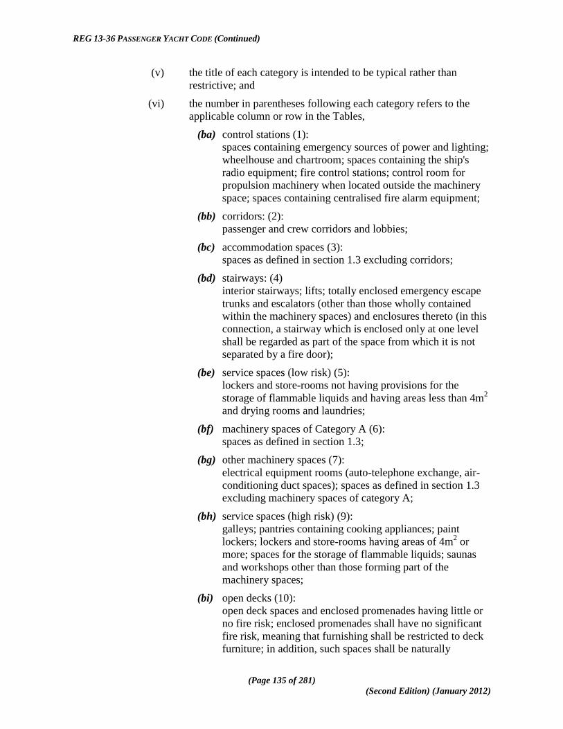
REG 13-36 PASSENGER YACHT CODE (Continued)
(Page 135 of 281)
(Second Edition) (January 2012)
(v) the title of each category is intended to be typical rather than
restrictive; and
(vi) the number in parentheses following each category refers to the
applicable column or row in the Tables,
(ba) control stations (1):
spaces containing emergency sources of power and lighting;
wheelhouse and chartroom; spaces containing the ship's
radio equipment; fire control stations; control room for
propulsion machinery when located outside the machinery
space; spaces containing centralised fire alarm equipment;
(bb) corridors: (2):
passenger and crew corridors and lobbies;
(bc) accommodation spaces (3):
spaces as defined in section 1.3 excluding corridors;
(bd) stairways: (4)
interior stairways; lifts; totally enclosed emergency escape
trunks and escalators (other than those wholly contained
within the machinery spaces) and enclosures thereto (in this
connection, a stairway which is enclosed only at one level
shall be regarded as part of the space from which it is not
separated by a fire door);
(be) service spaces (low risk) (5):
lockers and store-rooms not having provisions for the
storage of flammable liquids and having areas less than 4m2
and drying rooms and laundries;
(bf) machinery spaces of Category A (6):
spaces as defined in section 1.3;
(bg) other machinery spaces (7):
electrical equipment rooms (auto-telephone exchange, air-
conditioning duct spaces); spaces as defined in section 1.3
excluding machinery spaces of category A;
(bh) service spaces (high risk) (9):
galleys; pantries containing cooking appliances; paint
lockers; lockers and store-rooms having areas of 4m2 or
more; spaces for the storage of flammable liquids; saunas
and workshops other than those forming part of the
machinery spaces;
(bi) open decks (10):
open deck spaces and enclosed promenades having little or
no fire risk; enclosed promenades shall have no significant
fire risk, meaning that furnishing shall be restricted to deck
furniture; in addition, such spaces shall be naturally

REG 13-36 PASSENGER YACHT CODE (Continued)
(Page 136 of 281)
(Second Edition) (January 2012)
ventilated by permanent openings; air spaces (the space
outside superstructures and deckhouses); and
(bj) garage spaces (11):
spaces as defined in section 1.3.
(11) In determining the applicable fire integrity standard of a boundary between two spaces
within a main vertical zone or horizontal zone which is not protected by an automatic
sprinkler system complying with the provisions of the Fire Safety Systems Code or
between such zones neither of which is so protected, the higher of the two values
given in the tables shall apply.
(12) In determining the applicable fire integrity standard of a boundary between two spaces
within a main vertical zone or horizontal zone which is protected by an automatic
sprinkler system complying with the provisions of the Fire Safety Systems Code or
between such zones both of which are so protected, the lesser of the two values given
in the tables shall apply and where a zone with sprinklers and a zone without
sprinklers meet within accommodation and service spaces, the higher of the two
values given in the tables shall apply to the division between the zones.
(13) Continuous "B" class ceilings or linings, in association with the relevant decks or
bulkheads, may be accepted as contributing, wholly or in part, to the required
insulation and integrity of a division.
(14) External boundaries which are required in subsection 6.9(2) to be of steel or other
equivalent material may be pierced for the fitting of windows and sidescuttles
provided that there is no requirement for such boundaries to have "A" class integrity.
Similarly, in such boundaries which are not required to have "A" class integrity, doors
may be constructed of materials which are to the satisfaction of the Administration.
Construction and Arrangement of Saunas
(15) The perimeter of the sauna shall be of "A" class boundaries and may include changing
rooms, showers and toilets and the sauna shall be insulated to "A-60" standard against
other spaces except those inside of the perimeter of the sauna and spaces of low fire
risk such as open decks and low risk service spaces.
(16) Bathrooms with direct access to saunas may be considered as part of them. In such
cases, the door between sauna and the bathroom need not comply with fire safety
requirements.
(17) The traditional wooden lining on the bulkheads and ceiling are permitted in the sauna
provided that-
(a) the ceiling above the oven shall be lined with a non-combustible plate with an
air gap of at least 30 millimetres; and

REG 13-36 PASSENGER YACHT CODE (Continued)
(Page 137 of 281)
(Second Edition) (January 2012)
(b) the distance from the hot surfaces to combustible materials shall be at least 500
millimetres or the combustible materials shall be protected (e.g., non-
combustible plate with an air gap of at least 30 millimetres).
(18) The traditional wooden benches are permitted to be used in the sauna.
(19) The sauna door shall open outwards by pushing.
(20) Electrically heated ovens shall be provided with a timer.
Protection of Stairways and Lifts in Accommodation Area
(21) Stairways shall be within enclosures formed of "A" class divisions, with positive
means of closure at all openings, except that-
(a) a stairway connecting only two decks need not be enclosed, provided the
integrity of the deck is maintained by proper bulkheads or self-closing doors in
one 'tween-deck space; when a stairway is closed in one 'tween-deck space, the
stairway enclosure shall be protected in accordance with the Tables 6.1 and
6.2; and
(b) Stairways may be fitted in the open in a public space, provided they lie wholly
within the public space.
(22) Lift trunks shall be so fitted as to prevent the passage of smoke and flame from one
deck to another and shall be provided with means of closing so as to permit the control
of draught and smoke.
(23) Machinery for lifts located within stairway enclosures shall be arranged in a separate
room, surrounded by steel boundaries, provided that small passages for lift cables are
permitted.
(24) Lifts which open into spaces other than corridors, public spaces, special category
spaces, stairways and external areas shall not open into stairways included in the
means of escape.
(25) Non-load bearing partial bulkheads which separate adjacent cabin balconies shall be
capable of being opened by the crew from each side for the purpose of fighting fires.
Protection of Atriums:
(26) Atriums shall be within enclosures formed of ―A‖ class divisions having a fire rating
determined in accordance with Table 6.1.
(27) Decks separating spaces within atriums shall have a fire rating determined in
accordance with Table 6.2.

REG 13-36 PASSENGER YACHT CODE (Continued)
(Page 138 of 281)
(Second Edition) (January 2012)
Table 6.1 - Fire Integrity of Bulkheads separating Adjacent Spaces
SPACES
SOLAS
REF. NO. (1) (2) (3) (4) (5) (6) (7) (9) (10) (11)
▼ ►
Control stations
(1) A-0c A-0 A-60 A-0 A-15 A-60 A-15 A-60 * A-60
Corridors (2) Ce B-0e A-0c
B-0e B-0e A-60 A-0
A-15
A-0d * A-15
Accommodation spaces
(3) Ce A-0c
B-0e B-0e A-60 A-0
A-15
A-0d *
A-30 A-0d
Stairways (4) A-0c
B-0e
A-0c
B-0e A-60 A-0
A-15
A-0d * A-15
Service spaces (low risk)
(5) Ce A-60 A-0 A-0 * A-0
Machinery spaces of Category A
(6) * A-0 A-60 * A-60
Other machinery spaces
(7) A-0b A-0 * A-0
Service spaces (high risk)
(9) A-0b * A-30
Open decks
(10) * A-0
Garage spaces
(11) A-0

REG 13-36 PASSENGER YACHT CODE (Continued)
(Page 139 of 281)
(Second Edition) (January 2012)
Table 6.2 - Fire Integrity of Decks separating Adjacent Spaces
SPACES BELOW ▼
SPACES
ABOVE ►
(1) (2) (3) (4) (5) (6) (7) (9) (10) (11)
Control stations (1) A-0 A-0 A-0 A-0 A-0 A-60 A-0 A-0 * A-30
Corridors (2) A-0 * * A-0 * A-60 A-0 A-0 * A-0
Accommodation spaces
(3) A-60 A-0 * A-0 * A-60 A-0 A-0 * A-30 A-0d
Stairways (4) A-0 A-0 A-0 * A-0 A-60 A-0 A-0 * A-0
Service spaces (low risk)
(5) A-15 A-0 A-0 A-0 * A-60 A-0 A-0 * A-0
Machinery spaces of Category A
(6) A-60 A-60 A-60 A-60 A-60 * A-60f A-60 * A-60
Other machinery spaces
(7) A-15 A-0 A-0 A-0 A-0 A-0 * A-0 * A-0
Service spaces (high risk)
(9) A-60 A-30 A-0d
A-30 A-0d
A-30 A-0d
A-0 A-60 A-0 A-0 * A-30
Open decks (10) * * * * * * * * --- A-0
Garage spaces (11) A-60 A-15 A-30 A-0d
A-15 A-0 A-30 A-0 A-30 A-0 A-0
Notes: To be applied to both tables 6.1 and 6.2 as appropriate
(For clarification as to which applies, see subsections (7) & (8) and subsections (21) and (24))
b Where spaces are of the same numerical category and superscript "b" appears, a bulkhead or deck of the rating shown in the
tables is only required when the adjacent spaces are for a different purpose (e.g., in category (9)). A galley next to a galley
does not require a bulkhead, but a galley next to a paint room requires an "A-0" bulkhead.
c Bulkheads separating the wheelhouse and chartroom from each other may have a "B-0" rating. No fire rating is required for
those partitions separating the navigation bridge and the safety centre when the latter is within the navigation bridge.
d See subsections (11) and (12).
e For the application of subsection (3), "B-0" and "C", where appearing in Table 6.1, shall be read as "A-0".
f Fire insulation need not be fitted if the machinery space in category (7), in the opinion of the Administration, has little or no
fire risk.
* Where an asterisk appears in the Tables it indicates that-
(a) the division is required to be of steel or other equivalent material, but is not required to be of "A" class standard;
however, where a deck, except in a category (10) space, is penetrated for the passage of electric cables, pipes and
vent ducts, such penetrations shall be made tight to prevent the passage of flame and smoke;
(b) divisions between control stations (emergency generators) and open decks may have air intake openings without
means for closure; unless a fixed gas fire-extinguishing system is fitted in the control station;
(c) for the application of subsection 6.7(3), in Table 6.2, ―A‖ class divisions shall be read as "A-0", except for
category (10); and
(d) for the application of section 6.7(46), where-
(i) open decks, including external stairs, are used as escape routes, they shall be to class ―A-0‖ standard;
and
(ii) open decks are used as embarkation and assembly stations they shall be to class ―A-60‖ standard; and
(iii) areas in the ship‘s side are situated below survival craft launching positions, escape slide arrangements
or stowage areas for survival craft, such areas shall also be to class ―A-30‖ standard.

REG 13-36 PASSENGER YACHT CODE (Continued)
(Page 140 of 281)
(Second Edition) (January 2012)
Penetrations in Fire-Resisting Divisions and Prevention of Heat Transmission
(28) Where "A" class divisions are penetrated, such penetrations shall comply with the
following provisions-
(a) subject to the provisions of subsection (36), the penetrations shall be tested in
accordance with the Fire Test Procedures Code;
(b) in the case of ventilation ducts, subsections (57), (61) and (62) shall apply;
(c) where a pipe penetration is made of steel or equivalent material having a
thickness of 3 millimetres or greater and a length of not less than 900
millimetres (preferably 450 millimetres on each side of the division), and there
are no openings, testing is not required but such penetrations shall be suitably
insulated by extension of the insulation at the same level of the division being
penetrated.
(29) Where "B" class divisions are penetrated for the passage of electric cables, pipes,
trunks, ducts, etc., or for the fitting of ventilation terminals, lighting fixtures and
similar devices, such penetrations shall comply with the following provisions-
(a) subject to the provisions of subsection (63), arrangements shall be made to
ensure that the fire resistance is not impaired;
(b) pipes other than steel or copper that shall be protected by either-
(i) a fire-tested penetration device suitable for the fire resistance of the
division pierced and the type of pipe used; or
(ii) a steel sleeve, having a thickness of not less than 1.8 millimetres
and a length of not less than 900 millimetres for pipe diameters of
150 millimetres or more and not less than 600 millimetres for pipe
diameters of less than 150 millimetres (preferably equally divided
to each side of the division). The pipe shall be connected to the
ends of the sleeve by flanges or couplings; or the clearance between
the sleeve and the pipe shall not exceed 2.5 millimetres; or any
clearance between pipe and sleeve shall be made tight by means of
non-combustible or other suitable material.
(30) Uninsulated metallic pipes penetrating "A" or "B" class divisions shall be of materials
having a melting temperature which exceeds 950°C for "A-0" and 850°C for "B-0"
class divisions.
(31) In approving structural fire protection details, the Administration shall have regard to
the risk of heat transmission at intersections and terminal points of required thermal
barriers. The insulation of a deck or bulkhead shall be carried past the penetration,
intersection or terminal point for a distance of at least 450 millimetres in the case of
steel and aluminium structures. If a space is divided with a deck or a bulkhead of "A"
class standard having insulation of different values, the insulation with the higher

REG 13-36 PASSENGER YACHT CODE (Continued)
(Page 141 of 281)
(Second Edition) (January 2012)
value shall continue on the deck or bulkhead with the insulation of the lesser value for
a distance of at least 450 millimetres.
Protection of Openings in Fire-Resisting Divisions
(32) Openings shall be provided with permanently attached means of closing which shall
be at least as effective for resisting fires as the divisions in which they are fitted.
(33) The construction of doors and door frames in "A" class divisions, with the means of
securing them when closed, shall comply with the following provisions-
(a) the construction shall provide resistance to fire as well as to the passage of
smoke and flame equivalent to that of the bulkheads in which the doors are
situated, this being determined in accordance with the Fire Test Procedures
Code;
(b) doors and door frames shall be constructed of steel or other equivalent
material;
(c) watertight doors need not be insulated.
(34) It shall be possible for each door to be opened and closed from each side of the
bulkhead by one person only.
(35) Fire doors in main vertical zone bulkheads, galley boundaries and stairway enclosures
other than power-operated watertight doors and those which are normally locked shall
satisfy the following requirements:
(a) the doors shall be self-closing and be capable of closing with an angle of
inclination of up to 3.5° opposing closure;
(b) the approximate time of closure for hinged fire doors shall be no more than 40s
and no less than 10 seconds from the beginning of their movement with the
ship in upright position. The approximate uniform rate of closure for sliding
doors shall be of no more than 0.2 m/s and no less than 0.1 m/s with the ship in
upright position;
(c) the doors, except those for emergency escape trunks, shall be capable of
remote release from the continuously manned central control station, either
simultaneously or in groups, and shall be capable of release also individually
from a position at both sides of the door. Release switches shall have an on-off
function to prevent automatic resetting of the system;
(d) hold-back hooks not subject to central control station release are prohibited;
(e) a door closed remotely from the central control station shall be capable of
being re-opened from both sides of the door by local control. After such local
opening, the door shall automatically close again;
(f) indication shall be provided at the fire door indicator panel in the continuously
manned central control station whether each door is closed;

REG 13-36 PASSENGER YACHT CODE (Continued)
(Page 142 of 281)
(Second Edition) (January 2012)
(g) the release mechanism shall be so designed that the door will automatically
close in the event of disruption of the control system or central power supply;
(h) local power accumulators for power-operated doors shall be provided in the
immediate vicinity of the doors to enable the doors to be operated at least ten
times (fully opened and closed) after disruption of the control system or central
power supply using the local controls;
(i) disruption of the control system or central power supply at one door shall not
impair the safe functioning of the other doors;
(j) remote-released sliding or power-operated doors shall be equipped with an
alarm that sounds at least 5 seconds but no more than 10 seconds, after the
door is released from the central control station and before the door begins to
move and continues sounding until the door is completely closed;
(k) a door designed to re-open upon contacting an object in its path shall re-open
not more than 1 metre from the point of contact;
(l) double-leaf doors equipped with a latch necessary for their fire integrity shall
have a latch that is automatically activated by the operation of the doors when
released by the system;
(m) the components of the local control system shall be accessible for maintenance
and adjusting;
(n) power-operated doors shall be provided with a control system of an approved
type which shall be able to operate in case of fire and be in accordance with the
Fire Test Procedures Code. This system shall satisfy the following
requirements-
(i) the control system shall be able to operate the door at the
temperature of at least 200°C for at least 60 min, served by the
power supply;
(ii) the power for all other doors not subject to fire shall not be
impaired; and
(iii) at temperatures exceeding 200°C, the control system shall be
automatically isolated from the power supply and shall be capable
of keeping the door closed up to at least 945°C.
(36) Where a space is protected by an automatic sprinkler fire detection and fire alarm
system complying with the provisions of the Fire Safety Systems Code or fitted with a
continuous "B" class ceiling, openings in decks not forming steps in main vertical
zones nor bounding horizontal zones shall be closed reasonably tight and such decks
shall meet the "A" class integrity requirements in so far as is reasonable and
practicable in the opinion of the Administration.
(37) The requirements for "A" class integrity of the outer boundaries of a ship shall not
apply to-

REG 13-36 PASSENGER YACHT CODE (Continued)
(Page 143 of 281)
(Second Edition) (January 2012)
(a) glass partitions, windows and sidescuttles, provided that there is no
requirement for such boundaries to have "A" class integrity in subsection (46);
(b) exterior doors, except for those in superstructures and deckhouses facing life-
saving appliances, embarkation and external assembly station areas, external
stairs and open decks used for escape routes; and
(c) stairway enclosure doors.
(38) Except for watertight doors, weathertight doors, semi-watertight doors, doors leading
to the open deck and doors which need to be reasonably gastight, all "A" class doors
located in stairways, public spaces and main vertical zone bulkheads in escape routes
shall be equipped with a self-closing hose port, the material, construction and fire
resistance of which shall be equivalent to the door into which it is fitted, and the port
shall be a 150 millimetres square clear opening with the door closed and shall be inset
into the lower edge of the door, opposite the door hinges or, in the case of sliding
doors, nearest the opening.
(39) Ventilation ducts passing through main vertical zone divisions must be kept to a
minimum and where it is necessary that a such a duct passes through a main vertical
zone division, a fail-safe automatic closing fire damper shall be fitted adjacent to the
division complying with the following provisions-
(a) the damper shall be capable of being manually closed from each side of the
division;
(b) the operating position of the damper shall be readily accessible and be marked
in red light-reflecting colour;
(c) the duct between the division and the damper shall be of steel or other
equivalent material and, if necessary, insulated to comply with the
requirements of subsection (28); and
(d) the damper shall be fitted on at least one side of the division with a visible
indicator showing whether the damper is in the open position.
Openings in "B" Class Divisions
(40) Doors and door frames in "B" class divisions and means of securing them shall
provide a method of closure which shall have resistance to fire equivalent to that of the
divisions, this being determined in accordance with the Fire Test Procedures Code
provided that that ventilation openings may be permitted in the lower portion of such
doors as follows-
(a) where such opening is in or under a door the total net area of any such opening
or openings shall not exceed 0.05 m2;
(b) alternatively, a non-combustible air balance duct routed between the cabin and
the corridor, and located below the sanitary unit, is permitted where the cross-
sectional area of the duct does not exceed 0.05m2;
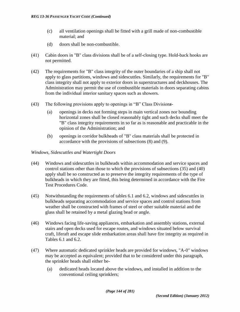
REG 13-36 PASSENGER YACHT CODE (Continued)
(Page 144 of 281)
(Second Edition) (January 2012)
(c) all ventilation openings shall be fitted with a grill made of non-combustible
material; and
(d) doors shall be non-combustible.
(41) Cabin doors in "B" class divisions shall be of a self-closing type. Hold-back hooks are
not permitted.
(42) The requirements for "B" class integrity of the outer boundaries of a ship shall not
apply to glass partitions, windows and sidescuttles. Similarly, the requirements for "B"
class integrity shall not apply to exterior doors in superstructures and deckhouses. The
Administration may permit the use of combustible materials in doors separating cabins
from the individual interior sanitary spaces such as showers.
(43) The following provisions apply to openings in ―B‖ Class Divisions-
(a) openings in decks not forming steps in main vertical zones nor bounding
horizontal zones shall be closed reasonably tight and such decks shall meet the
"B" class integrity requirements in so far as is reasonable and practicable in the
opinion of the Administration; and
(b) openings in corridor bulkheads of "B" class materials shall be protected in
accordance with the provisions of subsections (8) and (9).
Windows, Sidescuttles and Watertight Doors
(44) Windows and sidescuttles in bulkheads within accommodation and service spaces and
control stations other than those to which the provisions of subsections (35) and (40)
apply shall be so constructed as to preserve the integrity requirements of the type of
bulkheads in which they are fitted, this being determined in accordance with the Fire
Test Procedures Code.
(45) Notwithstanding the requirements of tables 6.1 and 6.2, windows and sidescuttles in
bulkheads separating accommodation and service spaces and control stations from
weather shall be constructed with frames of steel or other suitable material and the
glass shall be retained by a metal glazing bead or angle.
(46) Windows facing life-saving appliances, embarkation and assembly stations, external
stairs and open decks used for escape routes, and windows situated below survival
craft, liferaft and escape slide embarkation areas shall have fire integrity as required in
Tables 6.1 and 6.2.
(47) Where automatic dedicated sprinkler heads are provided for windows, "A-0" windows
may be accepted as equivalent; provided that to be considered under this paragraph,
the sprinkler heads shall either be-
(a) dedicated heads located above the windows, and installed in addition to the
conventional ceiling sprinklers;

REG 13-36 PASSENGER YACHT CODE (Continued)
(Page 145 of 281)
(Second Edition) (January 2012)
(b) conventional ceiling sprinkler heads arranged such that the window is
protected by an average application rate of at least 5l/min/m2 and the
additional window area is included in the calculation of the area of coverage;
or
(c) water-mist nozzles that have been tested and approved in accordance with the
guidelines approved by the IMO.
(48) Watertight doors need not be insulated.
Protection of Openings in Machinery Spaces Boundaries
(49) The provision of subsections (50) to (55) shall apply to machinery spaces of category
A and, where the Administration considers it desirable, to other machinery spaces.
(50) The number of skylights, doors, ventilators, openings in funnels to permit exhaust
ventilation and other openings to machinery spaces shall be reduced to a minimum
consistent with the needs of ventilation and the proper and safe working of the ship.
(51) Skylights shall be of steel and shall not contain glass panels.
(52) Means of control shall be provided for closing power-operated doors or actuating
release mechanisms on doors other than power-operated watertight doors and such
controls shall be located outside the space served so that they will not be cut off in the
event of fire in that place.
(53) The means of control required in subsection (52) shall be situated at one control
position or grouped in as few positions as possible to the satisfaction of the
Administration and such positions shall have safe access from the open deck.
(54) Doors, other than power-operated watertight doors, shall be so arranged that positive
closure is assured in case of fire in the space by power-operated closing arrangements
or by the provision of self-closing doors capable of closing against an inclination of
3.5° opposing closure, and having a fail-safe hold-back arrangement; provided with a
remotely operated release device; provided that doors for emergency escape trunks
need not be fitted with a fail-safe hold-back facility and a remotely operated release
device.
(55) Windows shall not be fitted in machinery space boundaries. However, this does not
preclude the use of glass in control rooms within the machinery spaces.

REG 13-36 PASSENGER YACHT CODE (Continued)
(Page 146 of 281)
(Second Edition) (January 2012)
Ventilation Systems
(56) Ventilation ducts shall be of non-combustible material. However, short ducts, not
generally exceeding 2 metres in length and with a free cross-sectional area37
not
exceeding 0.02 m2, need not be non-combustible, subject to the following conditions-
(a) the ducts are made of a material which has low flame-spread characteristics;
(b) the ducts are only used at the end of the ventilation device; and
(c) the ducts are not situated less than 600 millimetres, measured along the duct,
from an opening in an "A" or "B" class division, including continuous "B"
class ceiling.
(57) The following arrangements shall be tested in accordance with the Fire Test
Procedures Code-
(a) fire dampers, including their relevant means of operation; and
(b) duct penetrations through "A" class divisions. However, the test is not required
where steel sleeves are directly joined to ventilation ducts by means of riveted
or screwed flanges or by welding.
(58) The ventilation systems for machinery spaces of category A, garages and galleys shall,
in general, be separated from each other and from the ventilation systems serving
other spaces, except that the galley ventilation systems need not be completely
separated, but may be served by separate ducts from a ventilation unit serving other
spaces; in any case, an automatic fire damper shall be fitted in the galley ventilation
duct near the ventilation unit.
(59) Ducts provided for the ventilation of machinery spaces of category A, garages, galleys
and hazardous areas shall not pass through accommodation spaces, service spaces or
control stations provided that the Administration may permit a relaxation from this
requirement, other than for ducts serving hazardous areas, where the ducts comply
with the conditions specified in paragraphs (a) to (e) below-
(a) the ducts are constructed of steel having a thickness of at least 3 millimetres
and 5 millimetres for ducts the widths or diameters of which are up to and
including 300 millimetres and 760 millimetres and over respectively and, in
the case of such ducts, the widths or diameters of which are between 300
millimetres and 760 millimetres, having a thickness obtained by interpolation;
(b) the ducts are suitably supported and stiffened;
(c) the ducts are fitted with automatic fire dampers close to the boundaries
penetrated;
37
The term free cross-sectional area means, even in the case of a pre-insulated duct, the area calculated on the
basis of the inner diameter of the duct.

REG 13-36 PASSENGER YACHT CODE (Continued)
(Page 147 of 281)
(Second Edition) (January 2012)
(d) the ducts are-
(i) insulated to "A-60" class standard from the machinery spaces and
galleys to a point at least 5 metres beyond each fire damper; or
(ii) constructed of steel in accordance in accordance with paragraphs
(a) and (b) above and are insulated to "A-60" class standard
throughout the accommodation spaces, service spaces or control
stations; and
(e) penetrations of main zone divisions shall also comply with the requirements of
subsection (39).
(60) Ducts provided for ventilation to accommodation spaces, service spaces or control
stations shall not pass through machinery spaces of category A, garages, galleys and
hazardous areas provided that the Administration may permit a relaxation from this
requirement, other than for ducts passing through hazardous areas, where the ducts
comply with the conditions specified in paragraphs (a) to (b) below-
(a) the ducts, where they pass through a machinery space of category A, garage or
galley-
(i) are constructed of steel in accordance with paragraphs (a) and(b) of
subsection (59); and
(ii) are fitted with automatic fire dampers close to the boundaries
penetrated; and
(iii) maintain the integrity of the machinery space, garage or galley
boundaries at the penetrations; or
(b) the ducts, where they pass through a machinery space of category A, garage or
galley, are constructed of steel in accordance with paragraphs (a) and (b) of
subsection (59) and are insulated to "A-60" standard within the machinery
space of category A, garage or galley; and
(c) penetrations of main zone divisions shall also comply with the requirements of
subsection (39).
(61) Where a thin plated duct with a free cross-sectional area equal to, or less than, 0.02m2
passes through "A" class bulkheads or decks, the opening shall be lined with a steel
sheet sleeve having a thickness of at least 3 millimetres and a length of at least 200
millimetres, divided preferably into 100 millimetres on each side of the bulkhead or, in
the case of the deck, wholly laid on the lower side of the decks pierced.
(62) Where ventilation ducts with a free cross-sectional area exceeding 0.02mm2 pass
through "A" class bulkheads or decks, the opening shall be lined with a steel sheet
sleeve, provided that where such ducts are of steel construction and pass through a
deck or bulkhead, the ducts and sleeves shall comply with the following-
(a) the sleeves shall have a thickness of at least 3 millimetres and a length of at
least 900 millimetres;

REG 13-36 PASSENGER YACHT CODE (Continued)
(Page 148 of 281)
(Second Edition) (January 2012)
(b) when passing through bulkheads, the sleeves shall have their length divided
preferably into 450 millimetres on each side of the bulkhead;
(c) the ducts, or sleeves lining such ducts, shall be provided with fire insulation
which shall have at least the same fire integrity as the bulkhead or deck
through which the duct passes;
(d) ducts with a free cross-sectional area exceeding 0.075m2 shall be fitted with
fire dampers in addition to the requirements of subsection (55);
(e) the fire damper shall operate automatically, but shall also be capable of being
closed manually from both sides of the bulkhead or deck and the damper shall
be provided with an indicator which shows whether the damper is open or
closed provided that fire dampers are not required, however, where ducts pass
through spaces surrounded by "A" class divisions, without serving those
spaces, and those ducts have the same fire integrity as the divisions which they
pierce;
(f) fire dampers shall be easily accessible and where they are placed behind
ceilings or linings, these ceilings or linings shall be provided with an
inspection door on which a plate reporting the identification number of the fire
damper is provided; and
(g) the fire damper identification number shall also be placed on any remote
controls required.
(63) Ventilation ducts with a free cross-sectional area exceeding 0.02m2 passing through
"B" class bulkheads shall be lined with steel sheet sleeves of 900 millimetres in length,
divided preferably into 450 millimetres on each side of the bulkheads unless the duct
is of steel for this length.
(64) Where the exhaust ducts from galley ranges pass through accommodation spaces or
spaces containing combustible materials, they shall be constructed of "A" class
divisions. Each exhaust duct shall be fitted with-
(a) a grease trap readily removable for cleaning;
(b) a fire damper located in the lower end of the duct;
(c) arrangements, operable from within the galley, for shutting off the exhaust
fans; and
(d) fixed means for extinguishing a fire within the duct.
6.8 Fire Fighting:
Purpose
(1) The purpose of this paragraph is to suppress and swiftly extinguish a fire in the space
of origin by meeting the following functional requirements-

REG 13-36 PASSENGER YACHT CODE (Continued)
(Page 149 of 281)
(Second Edition) (January 2012)
(a) fixed fire-extinguishing systems shall be installed, having due regard to the fire
growth potential of the protected spaces; and
(b) fire-extinguishing appliances shall be readily available.
Water Supply Systems
(2) Ships shall be provided with fire pumps, fire mains, hydrants and hoses complying
with the applicable requirements of this paragraph.
(3) Fire mains and hydrants shall comply with the following provisions-
(a) materials readily rendered ineffective by heat shall not be used for fire mains
and hydrants unless adequately protected;
(b) the fire main pipes and hydrants shall be so placed that the fire hoses may be
easily coupled to them;
(c) the arrangement of pipes and hydrants shall be such as to avoid the possibility
of freezing;
(d) suitable drainage provisions shall be provided for fire main piping; and
(e) isolation valves shall be installed for all open deck fire main branches used for
purposes other than fire fighting.
(4) The arrangements for the ready availability of water supply shall be-
(a) ships of 1,000 gross tonnage and upwards such that at least one effective jet of
water is immediately available from any hydrant in an interior location and so
as to ensure the continuation of the output of water by the automatic starting of
one required fire pump;
(b) ships of less than 1,000 gross tonnage by automatic start of at least one fire
pump or by remote starting from the navigation bridge of at least one fire
pump. If the pump starts automatically or if the bottom valve cannot be opened
from where the pump is remotely started, the bottom valve shall always be
kept open; and
(c) if fitted with periodically unattended machinery space the Administration shall
determine provisions for fixed water fire-extinguishing arrangements for such
spaces equivalent to those required for normally attended machinery spaces.
(5) The diameter of the fire main and water service pipes shall be sufficient for the
effective distribution of the maximum required discharge from two fire pumps
operating simultaneously.
(6) Isolating valves, emergency fire pumps and their associated arrangements shall
comply with the following provisions-
(a) isolating valves which separate the section of the fire main within the
machinery space containing the main fire pump or pumps from the rest of the

REG 13-36 PASSENGER YACHT CODE (Continued)
(Page 150 of 281)
(Second Edition) (January 2012)
fire main shall be fitted in an easily accessible and tenable position outside the
machinery spaces;
(b) the fire main shall be so arranged that when the isolating valves are shut all the
hydrants on the ship, except those in the machinery space referred to above,
can be supplied with water by another fire pump or an emergency fire pump;
(c) subject to paragraph (d), the emergency fire pump, its seawater inlet, and
suction and delivery pipes and isolating valves shall be located outside the
machinery space;
(d) if the arrangement referred to in paragraph (c) cannot be complied with, the
sea-chest may be fitted in the machinery space if the valve is remotely
controlled from a position in the same compartment as the emergency fire
pump and the suction pipe is as short as practicable; and
(e) short lengths of suction or discharge piping may penetrate the machinery
space, provided such pipes-
(i) are enclosed in a substantial steel casing or are insulated to "A-60"
class standards;
(ii) have substantial wall thickness, but in no case less than 11
millimetres; and
(iii) shall be welded except for the flanged connection to the sea inlet
valve.
(7) A valve shall be fitted to serve each fire hydrant so that any fire hose may be removed
while the fire pumps are in operation.
(8) Relief valves shall be provided in conjunction with fire pumps if the pumps are
capable of developing a pressure exceeding the design pressure of the water service
pipes, hydrants and hoses. These valves shall be so placed and adjusted as to prevent
excessive pressure in any part of the fire main system.
(9) The number and position of hydrants shall be such that at least two jets of water not
emanating from the same hydrant, one of which shall be from a single length of hose,
may reach any part of the ship normally accessible, when the ship is being navigated,
to the passengers or crew.
(10) In addition to the requirements in subsection (9), ships shall comply with the
following-
(a) in the accommodation, service and machinery spaces, the number and position
of hydrants shall be such that the requirements of subsection (9) may be
complied with when all watertight doors and all doors in main vertical zone
bulkheads are closed; and
(b) where access is provided to a machinery space of category A at a low level
from an adjacent shaft tunnel, two hydrants shall be provided external to, but
near the entrance to, that machinery space. Where such access is provided from

REG 13-36 PASSENGER YACHT CODE (Continued)
(Page 151 of 281)
(Second Edition) (January 2012)
other spaces, in one of those spaces two hydrants shall be provided near the
entrance to the machinery space of category A. Such provision need not be
made where the tunnel or adjacent spaces are not part of the escape route.
(11) With the two pumps simultaneously delivering water through the nozzles specified in
subsection (22), with the quantity of water as specified in subsection (5), through any
adjacent hydrants, the following minimum pressures shall be maintained at all
hydrants-
Gross Tonnage Minimum Pressure
4000 and upwards 0.40 N/mm2
Less than 4000 0.30 N/mm2
provided that the maximum pressure at any hydrant shall not exceed that at which the
effective control of a fire hose can be demonstrated.
(12) Ships of 500 gross tonnage and upwards shall be provided with at least one
international shore connection complying with the Fire Safety Systems Code.
(13) Facilities shall be available enabling such a connection to be used on either side of the
ship.
(14) Sanitary, ballast, bilge or general service pumps may be accepted as fire pumps,
provided that they are not normally used for pumping oil.
(15) Ships shall be provided with independently driven fire pumps as follows:
Gross Tonnage No. of Pumps
4000 and upwards At least three
Less than 4000 At least two
(16) The arrangement of sea connections, fire pumps and their sources of power shall be as
to ensure that:
(a) in ships of l,000 gross tonnage and upwards, in the event of a fire in any one
compartment, all the fire pumps will not be put out of action; and
(b) in ships of less than 1,000 gross tonnage, if a fire in any one compartment
could put all the pumps out of action, there shall be an alternative means
consisting of an emergency fire pump complying with the provisions of the
Fire Safety Systems Code with its source of power and sea connection located
outside the space where the main fire pumps or their sources of power are
located.
(17) The space containing the emergency fire pump shall not be contiguous to the
boundaries of machinery spaces of category A or those spaces containing main fire
pumps; provided that where this is not practicable, the common bulkhead between the

REG 13-36 PASSENGER YACHT CODE (Continued)
(Page 152 of 281)
(Second Edition) (January 2012)
two spaces shall be insulated to a standard of structural fire protection equivalent to
that required for a control station.
(18) No direct access shall be permitted between the machinery space and the space
containing the emergency fire pump and its source of power, provided that-
(a) when this is impracticable, the Administration may accept an arrangement
where the access is by means of an airlock with the door of the machinery
space being of "A-60" class standard and the other door being at least steel,
both reasonably gastight, self-closing and without any hold-back arrangements;
(b) alternatively, the access may be through a watertight door capable of being
operated from a space remote from the machinery space and the space
containing the emergency fire pump and unlikely to be cut off in the event of
fire in those spaces; and
(c) a second means of access to the space containing the emergency fire pump and
its source of power shall be provided.
(19) Ventilation arrangements to the space containing the independent source of power for
the emergency fire pump shall be such as to preclude, as far as practicable, the
possibility of smoke from a machinery space fire entering or being drawn into that
space.
(20) The required fire pumps shall be capable of delivering for fire-fighting purposes a
quantity of water not less than two thirds of the quantity required to be dealt with by
the bilge pumps when employed for bilge pumping at the pressure specified in
subsection (11).
(21) Each of the required fire pumps shall-
(a) have a capacity not less than 80% of the total required capacity divided by the
minimum number of required fire pumps, but in any case not less than 25 m3/h
and each such pump shall in any event be capable of delivering at least the two
required jets of water;
(b) be capable of supplying the fire main system under the required conditions,
and where more pumps than the minimum of required pumps are installed, such
additional pumps shall have a capacity of at least 25m3/h and shall be capable of
delivering at least the two jets of water required in subsection (9).
(22) Fire hoses shall-
(a) be of non-perishable material approved by the Administration;
(b) be sufficient in length to project a jet of water to any of the spaces in which
they may be required to be used;
(c) each be provided with a nozzle and the necessary couplings;

REG 13-36 PASSENGER YACHT CODE (Continued)
(Page 153 of 281)
(Second Edition) (January 2012)
(d) where specified in this Chapter as "fire hoses", be kept ready for use in
conspicuous positions near the water service hydrants or connections, together
with any necessary fittings and tools; and
(e) have a length of at least 10 metres, but not more than-
(i) 15 metres in machinery spaces; and
(ii) 20 metres in other spaces and open decks.
(23) Unless one hose and nozzle is provided for each hydrant in the ship, there shall be
complete interchangeability of hose couplings and nozzles.
(24) Ships shall be provided with fire pumps, fire mains, hydrants and hoses complying
with the applicable requirements of this section.
(25) There shall be at least one fire hose for each of the hydrants required by subsections
(9) and (10) and these hoses shall be used only for the purposes of extinguishing fires
or testing the fire-extinguishing apparatus at fire drills and surveys.
(26) Standard nozzle sizes shall be 12 millimetres, 16 millimetres and 19 millimetres or as
near thereto as possible provided that larger diameter nozzles may be permitted at the
discretion of the Administration.
(27) For accommodation and service spaces, a nozzle size greater than 12 millimetres need
not be used.
(28) For machinery spaces and exterior locations, the nozzle size shall be such as to obtain
the maximum discharge possible from two jets at the pressure prescribed in subsection
(11) from the smallest pump, provided that a nozzle size greater than 19 millimetres
need not be used.
(29) Nozzles shall be of an approved dual-purpose type (i.e. spray/jet type) incorporating a
shutoff.
Portable fire extinguishers
(30) Portable fire extinguishers shall comply with the requirements of the Fire Safety
Systems Code.
(31) Accommodation spaces, service spaces and control stations shall be provided with
portable fire extinguishers of appropriate types and in sufficient number to the
satisfaction of the Administration; ships of 1,000 gross tonnage and upwards shall
carry at least five portable fire extinguishers.
(32) One of the portable fire extinguishers intended for use in any space shall be stowed
near the entrance to that space.

REG 13-36 PASSENGER YACHT CODE (Continued)
(Page 154 of 281)
(Second Edition) (January 2012)
(33) Carbon dioxide fire extinguishers shall not be placed in accommodation spaces. In
control stations and other spaces containing electrical or electronic equipment or
appliances necessary for the safety of the ship, fire extinguishers shall be provided
whose extinguishing media are neither electrically conductive nor harmful to the
equipment and appliances.
(34) Fire extinguishers shall be situated ready for use at easily visible places, which can be
reached quickly and easily at any time in the event of a fire, and in such a way that
their serviceability is not impaired by the weather, vibration or other external factors
and portable fire extinguishers shall be provided with devices which indicate whether
they have been used.
(35) Spare charges shall be provided for 100% of the first ten extinguishers and 50% of the
remaining fire extinguishers capable of being recharged on board provided that not
more than sixty total spare charges are required; instructions for recharging shall be
carried on board.
(36) For fire extinguishers which cannot be recharged on board, additional portable fire
extinguishers of the same quantity, type, capacity and number as determined in
subsection (35) above shall be provided in lieu of spare charges.
Fixed fire-extinguishing systems
(37) A fixed fire-extinguishing system required by subsection (44) below may be any of the
following systems-
(a) a fixed gas fire-extinguishing system complying with the provisions of the Fire
Safety Systems Code;
(b) a fixed high-expansion foam fire-extinguishing system complying with the
provisions of the Fire Safety Systems Code; and
(c) a fixed pressure water-spraying fire-extinguishing system complying with the
provisions of the Fire Safety Systems Code.
(38) Where a fixed fire-extinguishing system not required by this Chapter is installed, it
shall meet the requirements of the relevant requirements of this Chapter and the Fire
Safety Systems Code.
(39) Fire-extinguishing systems using Halon 1211, 1301, and 2402 and perfluorocarbons
shall be prohibited.
(40) In general, the Administration shall not permit the use of steam as a fire-extinguishing
medium in fixed fire-extinguishing systems.
(41) Where a fixed gas fire-extinguishing system is used, openings which may admit air to,
or allow gas to escape from, a protected space shall be capable of being closed from
outside the protected space.

REG 13-36 PASSENGER YACHT CODE (Continued)
(Page 155 of 281)
(Second Edition) (January 2012)
(42) When the fire-extinguishing medium is stored outside a protected space the storage
shall comply with the following provisions-
(a) the medium shall be stored in a room which is located behind the forward
collision bulkhead, and is used for no other purposes;
(b) any entrance to such a storage room shall preferably be from the open deck and
shall be independent of the protected space;
(c) where the storage space is located below deck, it shall be located no more than
one deck below the open deck and shall be directly accessible by a stairway or
ladder from the open deck;
(d) spaces which are located below deck or spaces where access from the open
deck is not provided shall be fitted with a mechanical ventilation system
designed to take exhaust air from the bottom of the space and shall be sized to
provide at least 6 air changes per hour;
(e) access doors shall open outwards, and bulkheads and decks, including doors
and other means of closing any opening therein, which form the boundaries
between such rooms and adjacent enclosed spaces shall be gastight; and
(f) for the purpose of the application of tables 6.1 and 6.2, such storage rooms
shall be treated as control stations.
(43) Pumps, other than those serving the fire main, required for the provision of water for
fire-extinguishing systems required by this Chapter, their sources of power and their
controls shall be installed outside the space or spaces protected by such systems and
shall be so arranged that a fire in the space or spaces protected will not put any such
system out of action.
Fire-Extinguishing Arrangements in Machinery Spaces
(44) Machinery spaces of category A shall be provided with any one of the fixed fire-
extinguishing systems in subsection (37) and in each case, if the engine-room and
boiler room are not entirely separate, or if fuel oil can drain from the boiler room into
the engine-room, the combined engine and boiler rooms shall be considered as one
compartment.
(45) There shall be provided in each Machinery space of category A-
(a) at least one portable foam applicator unit complying with the provisions of the
Fire Safety Systems Code;
(b) approved fire extinguishers, each of at least 45 litre capacity or equivalent,
sufficient in number to enable foam or its equivalent to be directed onto any
part of the fuel and lubricating oil pressure systems, gearing and other fire
hazards;
(c) in addition, there shall be provided a sufficient number of portable foam
extinguishers or equivalent which shall be so located that no point in the space

REG 13-36 PASSENGER YACHT CODE (Continued)
(Page 156 of 281)
(Second Edition) (January 2012)
is more than 10 metres walking distance from an extinguisher provided that
there are at least two such extinguishers in each space.
(46) Where, in the opinion of the Administration, a fire hazard exists in any machinery
space for which no specific provisions for fire-extinguishing appliances are prescribed
there shall be provided in, or adjacent to, that space such a number of approved
portable fire extinguishers or other means of fire extinction as the Administration may
deem sufficient.
(47) Subject to subsection (48), machinery spaces of category A of any size38
shall, in
addition to the fixed fire-extinguishing system required in subsection (44), be
protected by an approved type of fixed water-based or equivalent local application
fire-extinguishing system, based on the guidelines developed by the IMO39
and in the
case of periodically unattended machinery spaces, the fire-extinguishing system shall
have both automatic and manual release capabilities; in the case of continuously
manned machinery spaces, the fire-extinguishing system is only required to have a
manual release capability.
(48) The Administration may dispense with the requirement for a local application fire-
extinguishing system as required in subsection (47) in machinery spaces of category A
of less than 500m3 volume, taking due cognizance of the type of machinery installed in
such space.
(49) Fixed local application fire-extinguishing systems are to protect areas such as the
following without the necessity of engine shutdown, personnel evacuation, or sealing
of the spaces:
(a) the fire hazard portions of internal combustion machinery used for the ship's
main propulsion and power generation;
(b) boiler fronts;
(c) the fire hazard portions of incinerators; and
(d) purifiers for heated fuel oil.
(50) Activation of any local application system shall comply with the following provisions-
(a) activation shall give a visual and distinct audible alarm in the protected space
and at continuously manned stations;
(b) the alarm shall indicate the specific system activated; and
(c) the system alarm requirements described within this subsection are in addition
to, and not a substitute for, the detection and fire alarm system required
elsewhere in this Chapter.
38
Under SOLAS 74, this provision applies only to machinery spaces of Category A above 500m2 in volume.
39 Refer to the Guidelines for the approval of fixed water-based local application fire fighting systems for use in
Category A machinery spaces (MSC/Circ.913).

REG 13-36 PASSENGER YACHT CODE (Continued)
(Page 157 of 281)
(Second Edition) (January 2012)
Fire-Extinguishing Arrangements in Control Stations, Accommodation and Service Spaces
(51) An automatic sprinkler or water spray system shall be installed as required by section
6.5(10).
(52) A fixed pressure water-spraying fire-extinguishing system complying with the
provisions of the Fire Safety Systems Code shall be installed on cabin balconies of
ships to which 6.3(18) applies; where furniture and furnishings on such balconies are
not as defined in section 6.7(1)(d), subparagraphs (i),(ii), (iii), (vi) and (vii): provided
that this section need not apply where it is possible to readily direct a jet of water, for
fire fighting purposes, on to such a balcony from the deck immediately above and
where such balcony is not adjacent to life saving appliances.
(53) Paint lockers shall be protected by either-
(a) a carbon dioxide system, designed to give a minimum volume of free gas equal
to 40% of the gross volume of the protected space;
(b) a dry powder system, designed for at least 0.5 kg powder/m3;
(c) a water spraying or sprinkler system, designed for 5 l/m2 min. Water spraying
systems may be connected to the fire main of the ship; or
(d) a system providing equivalent protection, as determined by the Administration.
and in all cases, the system shall be operable from outside the protected space.
(54) Flammable liquid lockers shall be protected by an appropriate fire-extinguishing
arrangement approved by the Administration.
(55) For lockers of a deck area of less than 4m2, which do not give access to
accommodation spaces, a portable carbon dioxide fire extinguisher sized to provide a
minimum volume of free gas equal to 40% of the gross volume of the space may be
accepted in lieu of a fixed system provided that-
(a) a discharge port shall be arranged in the locker to allow the discharge of the
extinguisher without having to enter into the protected space;
(b) the required portable fire extinguisher shall be stowed adjacent to the port; and
(c) alternatively, a port or hose connection may be provided to facilitate the use of
fire main water.
(56) Deep-fat cooking equipment installed in enclosed spaces or on open decks shall be
fitted with the following-
(a) an automatic or manual fire-extinguishing system tested to an international
standard acceptable to the IMO40
;
40
Refer to the recommendations by the International Organization for Standardization, in particular publication
ISO 15371:2009, ―Fire-extinguishing systems for protection of galley cooking equipment.‖.

REG 13-36 PASSENGER YACHT CODE (Continued)
(Page 158 of 281)
(Second Edition) (January 2012)
(b) a primary and backup thermostat with an alarm to alert the operator in the
event of failure of either thermostat;
(c) arrangements for automatically shutting off the electrical power upon
activation of the fire-extinguishing system;
(d) an alarm for indicating operation of the fire-extinguishing system in the galley
where the equipment is installed; and
(e) controls for manual operation of the fire-extinguishing system which are
clearly labelled for ready use by the crew.
Fire-Fighter's Outfits
(57) Fire-fighter's outfits shall comply with the Fire Safety Systems Code.
(58) Ships shall carry-
(a) at least two fire-fighter's outfits;
(b) additionally, for every 80 metres, or part thereof, of the aggregate of the
lengths of all passenger spaces and service spaces on the deck which carries
such spaces or, if there is more than one such deck, on the deck which has the
largest aggregate of such lengths, two fire-fighter‘s outfits; and
(c) two sets of personal equipment, each set comprising the items stipulated in the
Fire Safety Systems Code.
(59) The fire-fighter‘s outfits or sets of personal equipment shall be kept ready for use in an
easily accessible location that is permanently and clearly marked and, where more
than one fire-fighter‘s outfit or more than one set of personal equipment is carried,
they shall be stored in widely separated positions.
(60) The Administration may require additional sets of personal equipment and breathing
apparatus, having due regard to the size and layout of the ship.
(61) Two spare charges shall be provided for each required breathing apparatus. Ships that
are equipped with suitably located means for fully recharging the air cylinders free
from contamination need carry only one spare charge for each required apparatus.
6.9 Structural Integrity:
Purpose
(1) The purpose of this paragraph is to maintain structural integrity of the ship, preventing
partial or whole collapse of the ship structures due to strength deterioration by heat.
For this purpose, materials used in the ships' structure shall ensure that the structural
integrity is not degraded due to fire.

REG 13-36 PASSENGER YACHT CODE (Continued)
(Page 159 of 281)
(Second Edition) (January 2012)
Material of Hull, Superstructures, Structural Bulkheads, Decks and Deckhouses
(2) The hull, superstructures, structural bulkheads, decks and deckhouses shall be
constructed of steel or other equivalent material and for the purpose of applying the
definition of steel or other equivalent material the "applicable fire exposure" shall be
according to the integrity and insulation standards given in Tables 6.1 and 6.2; for
example, where divisions such as decks or sides and ends of deckhouses are permitted
to have "B-0" fire integrity, the "applicable fire exposure" shall be half an hour.
Structure of Aluminium Alloy
(3) Unless otherwise specified in subsection(2), in cases where any part of the structure is
of aluminium alloy, the following shall apply-
(a) the insulation of aluminium alloy components of "A" or "B" class divisions,
except structure which, in the opinion of the Administration, is non-load-
bearing, shall be such that the temperature of the structural core does not rise
more than 200°C above the ambient temperature at any time during the
applicable fire exposure to the standard fire test; and
(b) special attention shall be given to the insulation of aluminium alloy
components of columns, stanchions and other structural members required to
support lifeboat and liferaft stowage, launching and embarkation areas, and
"A" and "B" class divisions to ensure-
(i) that for such members supporting lifeboat and liferaft areas and "A"
class divisions, the temperature rise limitation specified in
paragraph (a) above shall apply at the end of one hour; and
(ii) that for such members required to support "B" class divisions, the
temperature rise limitation specified in the said paragraph (a) shall
apply at the end of half an hour.
Machinery Spaces of Category A
(4) Subject to subsection (5), the boundaries of all machinery spaces of category A,
including crowns and casings, shall be of steel construction and shall be insulated as
required by Tables 6.1 and 6.2 as appropriate.
(5) The Administration may permit the boundaries of Category A machinery spaces,
including crowns and casings, to be constructed of aluminium provided that-
(a) the space is provided with an equivalent water-mist fire-extinguishing system
complying with MSC/Circ.116541
that will provide total flooding of the space
in the event of a fire in that space; and
41
Revised Guidelines for the approval of Equivalent Water-Based Fire Extinguishing Systems for Machinery
Spaces and Cargo Pump-Rooms, as further amended by MSC.1/Circ.1237.
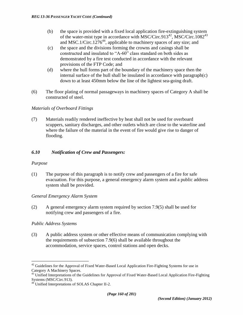
REG 13-36 PASSENGER YACHT CODE (Continued)
(Page 160 of 281)
(Second Edition) (January 2012)
(b) the space is provided with a fixed local application fire-extinguishing system
of the water-mist type in accordance with MSC/Circ.91342
, MSC/Circ.108243
and MSC.1/Circ.127644
, applicable to machinery spaces of any size; and
(c) the space and the divisions forming the crowns and casings shall be
constructed and insulated to ―A-60‖ class standard on both sides as
demonstrated by a fire test conducted in accordance with the relevant
provisions of the FTP Code; and
(d) where the hull forms part of the boundary of the machinery space then the
internal surface of the hull shall be insulated in accordance with paragraph(c)
down to at least 450mm below the line of the lightest sea-going draft.
(6) The floor plating of normal passageways in machinery spaces of Category A shall be
constructed of steel.
Materials of Overboard Fittings
(7) Materials readily rendered ineffective by heat shall not be used for overboard
scuppers, sanitary discharges, and other outlets which are close to the waterline and
where the failure of the material in the event of fire would give rise to danger of
flooding.
6.10 Notification of Crew and Passengers:
Purpose
(1) The purpose of this paragraph is to notify crew and passengers of a fire for safe
evacuation. For this purpose, a general emergency alarm system and a public address
system shall be provided.
General Emergency Alarm System
(2) A general emergency alarm system required by section 7.9(5) shall be used for
notifying crew and passengers of a fire.
Public Address Systems
(3) A public address system or other effective means of communication complying with
the requirements of subsection 7.9(6) shall be available throughout the
accommodation, service spaces, control stations and open decks.
42
Guidelines for the Approval of Fixed Water-Based Local Application Fire-Fighting Systems for use in
Category A Machinery Spaces. 43
Unified Interpretations of the Guidelines for Approval of Fixed Water-Based Local Application Fire-Fighting
Systems (MSC/Circ.913). 44
Unified Interpretations of SOLAS Chapter II-2.

REG 13-36 PASSENGER YACHT CODE (Continued)
(Page 161 of 281)
(Second Edition) (January 2012)
6.11 Means of Escape:
Purpose
(1) The purpose of this paragraph is to provide means of escape so that persons on board
can safely and swiftly escape to the lifeboat and liferaft embarkation deck. For this
purpose, the following functional requirements shall be met-
(a) safe escape routes shall be provided;
(b) escape routes shall be maintained in a safe condition, clear of obstacles; and
(c) additional aids for escape shall be provided as necessary to ensure
accessibility, clear marking, and adequate design for emergency situations.
General Requirements
(2) Unless expressly provided otherwise in this paragraph, at least two widely separated
and ready means of escape shall be provided from all spaces or groups of spaces.
(3) Lifts shall not be considered as forming one of the means of escape as required by this
paragraph.
Means of Escape from Control Stations, Accommodation Spaces and Service Spaces
(4) Stairways and ladders shall be so arranged as to provide ready means of escape to the
lifeboat and liferaft embarkation deck from passenger and crew accommodation
spaces and from spaces in which the crew is normally employed, other than machinery
spaces.
(5) A corridor, lobby, or part of a corridor from which there is only one route of escape
shall be prohibited, provided that-
(a) dead-end corridors used in service areas which are necessary for the practical
utility of the ship, such as fuel oil stations and athwartship supply corridors,
shall be permitted where such dead-end corridors are separated from crew
accommodation areas and are inaccessible from passenger accommodation
areas; and
(b) a part of a corridor that has a depth not exceeding its width is considered a
recess or local extension and is permitted.
(6) All stairways in accommodation and service spaces and control stations shall be of
steel frame construction except where the Administration sanctions the use of other
equivalent material.

REG 13-36 PASSENGER YACHT CODE (Continued)
(Page 162 of 281)
(Second Edition) (January 2012)
(7) If a radiotelegraph station has no direct access to the open deck, two means of escape
from, or access to, the station shall be provided, one of which may be a porthole or
window of sufficient size or other means to the satisfaction of the Administration.
(8) Doors in escape routes shall, in general, open in way of the direction of escape, except
that-
(a) individual cabin doors may open into the cabins in order to avoid injury to
persons in the corridor when the door is opened; and
(b) doors in vertical emergency escape trunks may open out of the trunk in order
to permit the trunk to be used both for escape and for access.
(9) Below the bulkhead deck, two means of escape, at least one of which shall be
independent of watertight doors, shall be provided from each watertight compartment
or similarly restricted space or group of spaces; provided that, exceptionally, the
Administration may dispense with one of the means of escape for crew spaces that are
entered only occasionally and where the required escape route is independent of
watertight doors.
(10) Where the Administration has granted dispensation under the provisions of subsection
(9), this sole means of escape shall provide safe escape and stairways shall not be less
than 800 millimetres in clear width with handrails on both sides.
(11) Above the bulkhead deck there shall be at least two means of escape from each main
vertical zone or similarly restricted space or group of spaces, at least one of which
shall give access to a stairway forming a vertical escape.
(12) Stairway enclosures in accommodation and service spaces shall comply with the
following provisions-
(a) they shall have direct access from the corridors and be of a sufficient area to
prevent congestion, having in view the number of persons likely to use them in
an emergency;
(b) within the perimeter of such stairway enclosures, only public toilets and
lockers of non-combustible material providing storage for non-hazardous
safety equipment are permitted;
(c) direct access to the stairway enclosures shall permitted only from the following
spaces-
(i) public spaces;
(ii) corridors;
(iii) lifts;
(iv) public toilets;
(v) lockers of non-combustible material providing storage for non-
hazardous safety equipment;

REG 13-36 PASSENGER YACHT CODE (Continued)
(Page 163 of 281)
(Second Edition) (January 2012)
(vi) garage spaces to which passengers can have access;
(vii) other escape stairways required by subsection (13); and
(viii) external areas;
(d) small corridors or "lobbies" used to separate an enclosed stairway from galleys
or laundries may have direct access to the stairway provided they have a
minimum deck area of 4.5 m2, a width of no less than 900 millimetres and
contain a fire hose station.
(13) At least one of the means of escape required by subsections (9) and (11) shall consist
of a readily accessible enclosed stairway which shall comply with the following
provisions-
(a) it shall provide continuous fire shelter from the level of its origin to the
appropriate lifeboat and liferaft embarkation decks, or to the uppermost
weather deck if the embarkation deck does not extend to the main vertical zone
being considered;
(b) where the latter case in paragraph (a) applies, direct access to the embarkation
deck by way of external open stairways and passageways shall be provided and
shall have emergency lighting in accordance with section 7.14 and slip-free
surfaces underfoot; and
(c) boundaries facing external open stairways and passageways forming part of an
escape route and boundaries in such a position that their failure during a fire
would impede escape to the embarkation deck shall have fire integrity,
including insulation values, in accordance with Tables 6.1 and 6.2, as
appropriate.
(14) Protection of access from the stairway enclosures to the lifeboat and liferaft
embarkation areas shall be provided either directly or through protected internal routes
which have fire integrity and insulation values for stairway enclosures as determined
by Tables 6.1 and 6.2, as appropriate.
(15) Stairways serving only a space and a balcony in that space shall not be considered as
forming one of the required means of escape.
(16) Each level within an atrium shall have two means of escape, one of which shall give
direct access to an enclosed vertical means of escape meeting the requirements of
subsection (13).
(17) The widths, number and continuity of escapes shall be in accordance with the
requirements in the Fire Safety Systems Code.

REG 13-36 PASSENGER YACHT CODE (Continued)
(Page 164 of 281)
(Second Edition) (January 2012)
(18) In addition to the emergency lighting supplied by the emergency source of electrical
power, the means of escape, including stairways and exits, shall comply with the
following provisions45
-
(a) subject to paragraph (b) shall be marked by lighting or photoluminescent strip
indicators placed not more than 300 mm above the deck at all points of the
escape route including angles and intersections such that the marking enables
passengers to identify the routes of escape and readily identify the escape
exits;
(b) alternative means of achieving safe escape other than lighting and or
photoluminescent strips may be considered by the Administration where such
alternative provides the same level of efficiency
(c) the marking or alternative means of achieving escape must enable passengers
to identify the routes of escape and readily identify the escape exits;
(d) all electrically operated systems shall be operated from the navigation bridge
or continuously manned Central Control Station and supplied by the
emergency source of power;
(e) lighting shall be so arranged that the failure of any single component will not
result in the system or any part thereof being rendered ineffective;
(f) additionally, escape route signs and fire equipment location markings shall be
of photoluminescent material or marked by lighting; and
(g) the Administration shall ensure that such lighting or photoluminescent
equipment used in compliance with this subsection has been evaluated, tested
and applied in accordance with the Fire Safety Systems Code.
(19) Cabin and stateroom doors shall not require keys to unlock them from inside the room.
Neither shall there be any doors along any designated escape route which require keys
to unlock them when moving in the direction of escape.
(20) Escape doors from public spaces that are normally latched shall be fitted with a means
of quick release arrangement consisting of a door-latching mechanism incorporating a
device that releases the latch upon the application of a force in the direction of escape
flow; such quick release mechanisms shall be designed and installed to the satisfaction
of the Administration46
.
(21) At least two emergency escape breathing devices shall be carried in each main vertical
zone.
45
See also MSC/Circular.1168 - Interim Guidelines for the Testing, Approval and Maintenance of Evacuation
Guidance Systems Used as an Alternative to Low-Location Lighting Systems. 46
Further requirements for quick release mechanisms are provided for in SOLAS 74 but are not applicable to
yachts to which the Code applies due to the fact that the Code limits the total number of persons on board to a
maximum of 99 and hence the number of persons (passengers and crew) expected to be situated in such
locations is limited.

REG 13-36 PASSENGER YACHT CODE (Continued)
(Page 165 of 281)
(Second Edition) (January 2012)
(22) Emergency escape breathing devices shall comply with the Fire Safety Systems Code.
Spare emergency escape breathing devices shall be kept on board.
Means of Escape from Machinery Spaces
(23) Where the space is below the bulkhead deck, the two means of escape shall consist of
either-
(a) two sets of steel ladders, as widely separated as possible, leading to doors in
the upper part of the space, similarly separated and from which access is
provided to the appropriate lifeboat and liferaft embarkation decks, provided
that-
(i) one of these ladders shall be located within a protected enclosure
that satisfies category (4), as appropriate, from the lower part of the
space it serves to a safe position outside the space;
(ii) self-closing fire doors of the same fire integrity standards shall be
fitted in the enclosure;
(iii) the ladder shall be fixed in such a way that heat is not transferred
into the enclosure through non-insulated fixing points; and
(iv) the protected enclosure shall have minimum internal dimensions of
at least 800 millimetres x 800 millimetres, and shall have
emergency lighting provisions; or
(b) one steel ladder leading to a door in the upper part of the space from which
access is provided to the embarkation deck and additionally, in the lower part
of the space and in a position well separated from the ladder referred to, a steel
door capable of being operated from each side and which provides access to a
safe escape route from the lower part of the space to the embarkation deck.
(24) Subject to subsection (25), where the space is above the bulkhead deck, the two means
of escape shall be as widely separated as possible and the doors leading from such
means of escape shall be in a position from which access is provided to the appropriate
lifeboat and liferaft embarkation decks and where such means of escape require the
use of ladders, these shall be of steel.
(25) The Administration may dispense with one of the means of escape required under
subsection (24) under the following conditions-
(a) in a ship of less than 1,000 gross tonnage due regard being paid to the width
and disposition of the upper part of the space;
(b) in a ship of 1,000 gross tonnage and above where either a door or a steel
ladder provides a safe escape route to the embarkation deck, due regard being
paid to the nature and location of the space and whether persons are normally
employed in that space and a space may include a normally unattended
auxiliary machinery space.

REG 13-36 PASSENGER YACHT CODE (Continued)
(Page 166 of 281)
(Second Edition) (January 2012)
(26) Two means of escape shall be provided from- a machinery control room located
within a machinery space, at least one of which will provide continuous fire shelter to
a safe position outside the machinery space.
(27) In the steering gear space, a second means of escape shall be provided when the
emergency steering position is located in that space unless there is direct access to the
open deck.
(28) On all ships, within the machinery spaces, emergency escape breathing devices which
comply with the Fire Safety Systems Code shall be situated ready for use at easily
visible places, which can be reached quickly and easily at any time in the event of fire
and the number and location of such devices shall be to the satisfaction of the
Administration and shall take into account the layout of the machinery spaces and the
number of persons normally working in the spaces.
(29) The number and location of the emergency escape breathing devices required under
subsection (28) shall be indicated in the fire control plan.
6.12 Operational Readiness and Maintenance:
Purpose
(1) The purpose of this paragraph is to maintain and monitor the effectiveness of the fire
safety measures the ship is provided with. For this purpose, the following functional
requirements shall be met-
(a) fire protection systems and fire-fighting systems and appliances shall be
maintained ready for use; and
(b) fire protection systems and fire-fighting systems and appliances shall be
properly tested and inspected.
General Requirements
(2) At all times while the ship is in service, the requirements of subsection 6.12(1)(a) shall
be complied with and a ship is not in service when-
(a) it is in for repairs or lay-up (either at anchor or in port) or in dry-dock;
(b) it is declared not in service by the owner or the owner's representative; or
(c) there are no passengers on board.
(3) The following fire protection systems shall be kept in good order so as to ensure their
required performance if a fire occurs-
(a) structural fire protection, including fire-resisting divisions, and protection of
openings and penetrations in these divisions;

REG 13-36 PASSENGER YACHT CODE (Continued)
(Page 167 of 281)
(Second Edition) (January 2012)
(b) fire detection and fire alarm systems; and
(c) means of escape systems and appliances.
(4) Fire-fighting systems and appliances shall be kept in good working order and readily
available for immediate use. Portable extinguishers which have been discharged shall
be immediately recharged or replaced with an equivalent unit.
(5) Maintenance, testing and inspections shall be carried out based on the guidelines
developed by the IMO47
and in a manner having due regard to ensuring the reliability
of fire-fighting systems and appliances.
(6) The maintenance plan shall be kept on board the ship and shall be available for
inspection whenever required by the Administration.
(7) The maintenance plan which may be computer based shall include at least the
following fire protection systems and fire-fighting systems and appliances, where
installed-
(a) fire mains, fire pumps and hydrants, including hoses, nozzles and international
shore connections;
(b) fixed fire detection and fire alarm systems;
(c) fixed fire-extinguishing systems and other fire-extinguishing appliances;
(d) automatic sprinkler, fire detection and fire alarm systems;
(e) ventilation systems, including fire and smoke dampers, fans and their controls;
(f) emergency shutdown of fuel supply;
(g) fire doors, including their controls;
(h) general emergency alarm systems;
(i) emergency escape breathing devices;
(j) portable fire extinguishers, including spare charges; and
(k) fire-fighter's outfits.
6.13 Instructions, On-board Training and Drills:
Purpose
(1) The purpose of this paragraph is to mitigate the consequences of fire by means of
proper instructions for training and drills of persons on board in correct procedures
47
Refer to the Guidelines on maintenance and inspection of fire protection systems and appliances
(MSC/Circ.850).

REG 13-36 PASSENGER YACHT CODE (Continued)
(Page 168 of 281)
(Second Edition) (January 2012)
under emergency conditions and for this purpose, the crew shall have the necessary
knowledge and skills to handle fire emergency cases, including passenger care.
General Requirements
(2) Crew members shall receive instruction on fire safety on board the ship.
(3) Crew members shall receive instructions on their assigned duties.
(4) Parties responsible for fire extinguishing shall be organised and such parties shall have
the capability to complete their duties at all times while the ship is in service.
(5) Crew members shall be trained to be familiar with the arrangements of the ship as well
as the location and operation of any fire-fighting systems and appliances that they may
be called upon to use.
(6) Training in the use of the emergency escape breathing devices shall be considered as
part of on-board training.
(7) Performance of crew members‘ assigned fire-fighting duties shall be periodically
evaluated by conducting on-board training and drills to identify areas in need of
improvement, to ensure competency in fire-fighting skills is maintained, and to ensure
the operational readiness of the fire-fighting organisation.
(8) On-board training in the use of the ship's fire-extinguishing systems and appliances
shall be planned and conducted in accordance with the provisions of section 7.17(17).
(9) Fire drills shall be conducted and recorded in accordance with the provisions of
section 7.17.
(10) A training manual shall be provided in each crew mess room and recreation room or in
each crew cabin.
(11) The training manual shall be written in the working language of the ship.
(12) The training manual, which may comprise several volumes, shall contain the
instructions and information required in subsection (13) in easily understood terms and
illustrated wherever possible; any part of such information may be provided in the
form of audio-visual aids in lieu of the manual.
(13) The training manual shall explain the following in detail-
(a) general fire safety practice and precautions related to the dangers of smoking,
electrical hazards, flammable liquids and similar common shipboard hazards;
(b) general instructions on fire-fighting activities and fire-fighting procedures,
including procedures for notification of a fire and use of manually operated
call points;

REG 13-36 PASSENGER YACHT CODE (Continued)
(Page 169 of 281)
(Second Edition) (January 2012)
(c) meanings of the ship's alarms;
(d) operation and use of fire-fighting systems and appliances;
(e) operation and use of fire doors;
(f) operation and use of fire and smoke dampers; and
(g) escape systems and appliances.
(14) General arrangement plans48
shall be permanently exhibited for the guidance of the
ship's officers, showing clearly for each deck the control stations, the various fire
sections enclosed by "A" class divisions, the sections enclosed by "B" class divisions
together with particulars of the fire detection and fire alarm systems, the sprinkler
installation, the fire-extinguishing appliances, means of access to different
compartments, decks, etc., and the ventilating system, including particulars of the fan
control positions, the position of dampers and identification numbers of the ventilating
fans serving each section; provided that as an alternative, at the discretion of the
Administration, the aforementioned details may be set out in a booklet, a copy of
which shall be supplied to each officer, and one copy shall at all times be available on
board in an accessible position and in any case plans and booklets shall be kept up to
date; any alterations thereto shall be recorded as soon as practicable and the
description in such plans and booklets shall be in English.
(15) A duplicate set of fire control plans or a booklet containing such plans shall be
permanently stored in a prominently marked weathertight enclosure outside the
deckhouse for the assistance of shore-side fire-fighting personnel49
.
(16) In addition to the requirement of section 7.17, fire drills shall be conducted in
accordance with the provisions of section 7.18 of the Code having due regard to
notification of passengers and movement of passengers to assembly stations and
embarkation decks.
6.14 Operations:
Purpose
(1) The purpose of this paragraph is to provide information and instructions for proper
ship handling operations in relation to fire safety and for this purpose, fire safety
operational booklets shall be provided on board.
(2) The required fire safety operational booklet shall contain the necessary information
and instructions for the safe operation of the ship in relation to fire safety and the
48
Refer to Graphical symbols for fire control plans, adopted by the IMO by Resolution A.654(16) and
Resolution A.952(23) - Graphical Symbols for Shipboard Fire Control Plans for ships constructed on or after
041 January 2004. 49
Refer to the Guidance concerning the location of fire control plans for assistance of shoreside fire-fighting
personnel (MSC/Circ.451).

REG 13-36 PASSENGER YACHT CODE (Continued)
(Page 170 of 281)
(Second Edition) (January 2012)
booklet shall include information concerning the crew's responsibilities for the general
fire safety of the ship at all times.
(3) The fire safety operational booklet shall be in the working language of the ship and
shall be provided in each crew mess room and recreation room or in each crew cabin.
(4) The fire safety operational booklet may be combined with the training manuals
required in subsection section 6.13(10).
6.15 Alternative Design and Arrangements:
Purpose
(1) The purpose of this paragraph is to provide a methodology for alternative design and
arrangements for fire safety.
General
(2) Fire safety design and arrangements may deviate from the prescriptive requirements
set out in this Chapter, provided that the design and arrangements meet the fire safety
objectives and the functional requirements.
(3) When fire safety design or arrangements deviate from the prescriptive requirements of
this Chapter, engineering analysis, evaluation and approval of the alternative design
and arrangements shall be carried out in accordance with this paragraph.
Engineering Analysis
(4) The engineering analysis shall be prepared and submitted to the Administration, based
on the guidelines developed by the IMO50
, and shall include, as a minimum, the
following elements-
(a) determination of the ship type and space(s) concerned;
(b) identification of prescriptive requirement(s) with which the ship or the space(s)
will not comply;
(c) identification of the fire and explosion hazards of the ship or the space(s)
concerned, including:
(i) identification of the possible ignition sources;
(ii) identification of the fire growth potential of each space concerned;
(iii) identification of the smoke and toxic effluent generation potential
for each space concerned;
50
Refer to the Guidelines on alternative design and arrangements for Fire Safety (MSC/Circ.1002).

REG 13-36 PASSENGER YACHT CODE (Continued)
(Page 171 of 281)
(Second Edition) (January 2012)
(iv) identification of the potential for the spread of fire, smoke or of
toxic effluents from the space(s) concerned to other spaces;
(d) determination of the required fire safety performance criteria for the ships or
the space(s) concerned addressed by the prescriptive requirement(s), in
particular-
(i) performance criteria shall be based on the fire safety objectives and
on the functional requirements of this Chapter;
(ii) performance criteria shall provide a degree of safety not less than
that achieved by using the prescriptive requirements; and
(iii) performance criteria shall be quantifiable and measurable;
(e) detailed description of the alternative design and arrangements, including a list
of the assumptions used in the design and any proposed operational restrictions
or conditions; and
(f) technical justification demonstrating that the alternative design and
arrangements meet the required fire safety performance criteria.
Evaluation of Alternative Design and Arrangements
(5) The engineering analysis required in subsection (4) shall be evaluated and approved
by the Administration, taking into account the guidelines developed by the IMO.51
(6) A copy of the documentation, as approved by the Administration, indicating that the
alternative design and arrangements comply with this paragraph shall be carried on
board the ship.
Exchange of Information
(7) The Administration shall communicate to the IMO pertinent information concerning
alternative design and arrangements approved by them for circulation to all
Contracting Governments.
Re-evaluation due to Change of Conditions
(8) If the assumptions and operational restrictions that were stipulated in the alternative
design and arrangements are changed, the engineering analysis shall be carried out
under the changed condition and shall be approved by the Administration.
51
Refer to the Guidelines on alternative design and arrangements for fire safety (MSC/Circ.1002).

REG 13-36 PASSENGER YACHT CODE (Continued)
(Page 172 of 281)
(Second Edition) (January 2012)
6.16 Helicopter Facilities:
Purpose
(1) The purpose of this regulation is to provide additional measures in order to address the
fire safety objectives of this chapter for ships fitted with special facilities for
helicopters and for this purpose, the following functional requirements shall be met-
(a) helideck structure must be adequate to protect the ship from the fire hazards
associated with helicopter operations;
(b) fire-fighting appliances shall be provided to adequately protect the ship from
the fire hazards associated with helicopter operations; refuelling and hangar
facilities and operations shall provide the necessary measures to protect the
ship from the fire hazards associated with helicopter operations; and
(c) operation manuals and training shall be provided.
Application
(2) This section applies to all passenger yachts to which the Code applies and on which
helicopter operations take place and the provisions of this section are to be read and
applied in conjunction with the applicable requirements and guidance relating to
Helicopter Landing Areas contained in Annex 2 to the Code.
(3) In addition to complying with the applicable requirements of sections 6.1 to 6.15 ships
equipped with helidecks shall comply with the requirements of this section.
(4) Where helicopters land or conduct winching operations on an occasional or emergency
basis on ships without helidecks, fire-fighting equipment fitted in accordance with the
requirements of section 6.8 may be used and this equipment shall be made readily
available in close proximity to the landing or winching areas during helicopter
operations.
Structure-Steel or other Equivalent Material
(5) In general, the construction of the helidecks shall be of steel or other equivalent
materials. If the helideck forms the deckhead of a deckhouse or superstructure, it shall
be insulated to "A-60" class standard.
Structure-Aluminium or other Low Melting Point Metals
(6) If the Administration permits aluminium or other low melting point metal construction
that is not made equivalent to steel, the following provisions shall be satisfied-
(a) if the platform is cantilevered over the side of the ship, after each fire on the
ship or on the platform, the platform shall undergo a structural analysis to
determine its suitability for further use; and

REG 13-36 PASSENGER YACHT CODE (Continued)
(Page 173 of 281)
(Second Edition) (January 2012)
(b) if the platform is located above the ship‘s deckhouse or similar structure, the
following conditions shall be satisfied-
(i) the deckhouse top and bulkheads under the platform shall have no
openings;
(ii) windows under the platform shall be provided with steel shutters; and
(iii) after each fire on the platform or in close proximity, the platform shall
undergo a structural analysis to determine its suitability for further use.
Means of Escape
(7) A helideck shall be provided with both a main and an emergency means of escape and
access for fire fighting and rescue personnel. These shall be located as far apart from
each other as is practicable and preferably on opposite sides of the helideck.
Fire Fighting Appliances
(8) The following fire-fighting appliances shall be provided in close proximity to the
helideck and stored near the means of access to that helideck-
(a) at least two dry powder extinguishers having a total capacity of not less than 45
kg;
(b) carbon dioxide extinguishers of a total capacity of not less than 18 kg or
equivalent;
(c) a suitable foam application system consisting of monitors or foam making
branch pipes capable of delivering foam to all parts of the helideck in all
weather conditions in which helicopters can operate and which shall be capable
of delivering a discharge rate as required in Table 6.3 for at least five minutes;
(d) the principal agent shall be suitable for use with salt water and conform to
performance standards not inferior to those acceptable to the IMO52
;
(e) at least two nozzles of an approved dual-purpose type (jet/spray) and hoses
sufficient to reach any part of the helideck;
(f) in addition to the requirements of subsection 6.8(57), two sets of fire-fighter‘s
outfits; and
(g) at least the following equipment shall be stored in a manner that provides for
immediate use and protection from the elements-
(i) adjustable wrench
(ii) blanket, fire resistant;
52
Refer to the International Civil Aviation Organization Airport Services Manual, part 1, Rescue and Fire
Fighting, chapter 8, Extinguishing Agent Characteristics, Paragraph 8.1.5, Foam Specifications table 8-1, Level
―B".

REG 13-36 PASSENGER YACHT CODE (Continued)
(Page 174 of 281)
(Second Edition) (January 2012)
(iii) cutters, bolt, 60 cm;
(iv) hook, grab or salving;
(v) hacksaw, heavy duty complete with 6 spare blades;
(vi) ladder;
(vii) lift line 5 mm diameter × 15 m in length;
(viii) pliers, side-cutting;
(ix) set of assorted screwdrivers; and
(x) harness knife complete with sheath.
Table 6.3 Foam discharge rates
Category Helicopter overall length Discharge rate foam
solution (l/min)
H1 up to but not including 15m 250
H2 from 15m up to but not
including 24m
500
H3 from 24m up to but not
including 35m
800
Drainage Facilities
(9) Drainage facilities in way of helidecks shall be constructed of steel and shall lead
directly overboard independent of any other system and shall be designed so that
drainage does not fall onto any part of the ship.
Helicopter Re-fuelling and Hangar facilities
(10) Where the ship has helicopter refuelling and hangar facilities, the following
requirements shall be complied with-
(a) a designated area shall be provided for the storage of fuel tanks which shall
be-
(i) as remote as is practicable from accommodation spaces, escape
routes and embarkation stations; and
(ii) isolated from areas containing a source of vapour ignition.
(b) the fuel storage area shall be provided with arrangements whereby fuel
spillage may be collected and drained to a safe location;
(c) tanks and associated equipment shall be protected against physical damage
and from a fire in an adjacent space or area;
(d) where portable fuel storage tanks are used, special attention shall be given to-

REG 13-36 PASSENGER YACHT CODE (Continued)
(Page 175 of 281)
(Second Edition) (January 2012)
(i) design of the tank for its intended purpose;
(ii) mounting and securing arrangements;
(iii) electric bonding; and
(iv) inspection procedures;
(e) storage tank fuel pumps shall be provided with means which permit shutdown
from a safe remote location in the event of a fire and where a gravity fuelling
system is installed, equivalent closing arrangements shall be provided to
isolate the fuel source;
(f) the fuel pumping unit shall be connected to one tank at a time and the piping
between the tank and the pumping unit shall be of steel or equivalent material,
as short as possible, and protected against damage;
(g) electrical fuel pumping units and associated control equipment shall be of a
type suitable for the location and potential hazards;
(h) fuel pumping units shall incorporate a device which will prevent over-
pressurization of the delivery or filling hose;
(i) equipment used in refuelling operations shall be electrically bonded;
(j) ―NO SMOKING" signs shall be displayed at appropriate locations;
(k) hangar, refuelling and maintenance facilities shall be treated as category ‗A‘
machinery spaces with regard to structural fire protection, fixed fire-
extinguishing and detection system requirements;
(l) enclosed hangar facilities or enclosed spaces containing refuelling installations
shall be provided with mechanical ventilation, as required by section 6.17(3)
for garage spaces and ventilation fans shall be of non-sparking type; and
(m) electric equipment and wiring in enclosed hangar or enclosed spaces
containing refuelling installations shall also comply with requirements of
section 6.17(9).
Operational Manual and Fire Fighting Service
(11) Each helicopter facility shall have an operations manual, including a description and a
checklist of safety precautions, procedures and equipment requirements. This manual
may be part of the ship‘s emergency response procedures.
(12) The procedures and precautions to be followed during refuelling operations shall be in
accordance with recognized safe practices and contained in the operations manual.
(13) Fire-fighting personnel, consisting of at least two persons trained for rescue and fire-
fighting duties, and fire-fighting equipment shall be immediately available at all times
when helicopter operations are expected.

REG 13-36 PASSENGER YACHT CODE (Continued)
(Page 176 of 281)
(Second Edition) (January 2012)
(14) On-board refresher training shall be carried out and additional supplies of fire-fighting
media shall be provided for training and testing of the equipment.
6.17 Protection of Garage Spaces:
Purpose
(1) The purpose of this paragraph is to provide additional safety measures in order to
address the fire safety objectives of this Chapter for ships fitted with garage spaces
and for this purpose, the following functional requirements shall be met:
(a) fire protection systems shall be provided to adequately protect the ship from
the fire hazards associated with garage spaces;
(b) sources of ignition shall be separated from garage spaces; and
(c) garage spaces shall be adequately ventilated.
Application
(2) In addition to complying with the requirements of this Chapter, as appropriate,
garage spaces shall also comply with the requirements of this paragraph.
Measures
(3) There shall be provided an effective power ventilation system sufficient to give at least
6 air changes per hour which shall comply with the following provisions-
(a) it shall be separate from other ventilation systems and shall be in operation at
all times;
(b) ventilation ducts serving such spaces capable of being effectively sealed shall
be separated for each such space; and
(c) the system shall be capable of being controlled from a position outside such
spaces.
(4) The ventilation system shall be such as to prevent air stratification and the formation
of air pockets.
(5) Means shall be provided on the navigation bridge to indicate any loss of the required
ventilating capacity.
(6) Arrangements shall be provided to permit a rapid shutdown and effective closure of
the ventilation system from outside of the space in case of fire, taking into account the
weather and sea conditions.

REG 13-36 PASSENGER YACHT CODE (Continued)
(Page 177 of 281)
(Second Edition) (January 2012)
(7) Ventilation ducts, including dampers, shall be made of steel and ventilation ducts that
pass through other horizontal zones or machinery spaces shall be "A-60" class steel
ducts.
(8) Permanent openings in the side plating, the ends or deckhead of the space shall be so
situated that a fire in the garage space does not endanger stowage areas and
embarkation stations for survival craft and accommodation spaces, service spaces and
control stations in superstructures and deckhouses above the garage spaces.
(9) Electrical equipment and wiring shall be of a type suitable for use in an explosive
petrol and air mixture.53
(10) Electrical equipment and wiring, if installed in an exhaust ventilation duct, shall be of
a type approved for use in explosive petrol and air mixtures and the outlet from any
exhaust duct shall be sited in a safe position, having regard to other possible sources
of ignition.
(11) Other equipment which may constitute a source of ignition of flammable vapours shall
not be permitted.
(12) Smoking shall not be permitted and “No-Smoking” signs are to be prominently
displayed.
(13) Scuppers, piping and drainage connections for the space are to be non-combustible
and shall not be led to machinery or other spaces where sources of ignition may be
present.
(14) Garage spaces are not to give direct access to any space other than a fuel store or
lockers used within the space, unless provided with a lobby in accordance with the fire
integrity requirements of Tables 6.1 and 6.2 and the provisions of section 2.6 with
respect to Load Lines are also to be complied as with as applicable.
(15) There shall be provided a fixed fire detection and fire alarm system complying with
the requirements of the Fire Safety Systems Code and with the following provisions-
(a) the fixed fire detection system shall be capable of rapidly detecting the onset of
fire;
(b) the type of detectors and their spacing and location shall be to the satisfaction
of the Administration, taking into account the effects of ventilation and other
relevant factors; and
(c) after being installed, the system shall be tested under normal ventilation
conditions and shall give an overall response time to the satisfaction of the
Administration.
53
Refer to the recommendations of the International Electrotechnical Commission, in particular publication
60079.

REG 13-36 PASSENGER YACHT CODE (Continued)
(Page 178 of 281)
(Second Edition) (January 2012)
(16) Manually operated call points shall be spaced so that no part of the space is more
than 20m from a manually operated call point, and one shall be placed close to each
exit from such spaces.
(17) The boundary bulkheads and decks of garage spaces shall have fire integrity in
accordance with Tables 6.1 and 6.2.
(18) Garage space shall be fitted with a fixed pressure water-spray fire-extinguishing
system which shall comply with the Fire Safety Systems Code; provided that the
Administration may permit the use of any other fixed fire-extinguishing system54
that
has been shown, by a full-scale test in conditions simulating a flowing petrol fire in a
vehicle space or a ro-ro space, to be not less effective in controlling fires likely to
occur in a garage space.
(19) When fixed pressure water-spray fire-extinguishing systems are provided, in view of
the serious loss of stability which could arise55
due to large quantities of water
accumulating on the deck or decks during the operation of the water-spraying system,
the following arrangements shall be provided:
(a) in the spaces above the bulkhead deck, scuppers shall be fitted so as to ensure
that such water is rapidly discharged directly overboard;
(b) in the spaces below the bulkhead deck, the Administration may require
additional pumping and drainage facilities and in such case-
(i) the drainage system shall be sized to remove no less than 125% of
the combined capacity of both the water-spraying system pumps
and the required number of fire hose nozzles; and
(ii) the drainage system valves shall be operable from outside the
protected space at a position in the vicinity of the extinguishing
system controls.
(20) At least two portable foam fire extinguishers or equivalent shall be provided at each
deck level in each garage space and at least one portable fire extinguisher shall be
located at each access to such space.
54
Refer to the Guidelines for the approval of alternative fixed water-based fire-fighting systems for special
category spaces (See MSC/Circ.1272). 55
Attention is drawn to IMO Resolution MSC.256(84) and the associated Circular MSC/Circ.1320 (paragraphs
1.1.2 and 3.1.1), with respect to the drainage of fire fighting water from spaces above the bulkhead deck in
passenger ships.

REG 13-36 PASSENGER YACHT CODE (Continued)
(Page 179 of 281)
(Second Edition) (January 2012)
CHAPTER 7
LIFE-SAVING APPLIANCES AND ARRANGEMENTS
7.1 Application:
SOLAS regulations referenced in this Chapter apply to ships to which this Code applies in the
same way as they apply to passenger ships.
7.2 General Requirements:
(1) Except as provided in subsections (5) and (6), life-saving appliances, communication
equipment and arrangements required by this Chapter shall be approved by the
Administration.
(2) Before giving approval to life-saving appliances and arrangements, the Administration
shall ensure that such life-saving appliances and arrangements-
(a) are tested, to confirm that they comply with the requirements of this Chapter
and the LSA Code; or
(b) have successfully undergone, to the satisfaction of the Administration, tests
which are substantially equivalent to those specified.
(3) Prior to giving approval to novel life-saving appliances or arrangements, the
Administration shall ensure that such appliances or arrangements-
(a) provide safety standards at least equivalent to the requirements of this Chapter
and the LSA Code and have been evaluated and tested in accordance with the
recommendations of the IMO; or
(b) have successfully undergone, an engineering analysis, evaluation and approval
in accordance with section 7.26.
(4) Procedures adopted by the Administration for approval shall also include the
conditions whereby approval would continue or would be withdrawn.
(5) Prior to accepting life-saving appliances and arrangements that have not been
previously approved by the Administration, the Administration shall be satisfied that
life-saving appliances and arrangements comply with the requirements of this Chapter
and the LSA Code.
(6) Life-saving appliances required by this Chapter for which detailed specifications are
not included in the LSA Code shall be to the satisfaction of the Administration.

REG 13-36 PASSENGER YACHT CODE (Continued)
(Page 180 of 281)
(Second Edition) (January 2012)
7.3 Stowage of Survival Craft:
(1) Each survival craft shall be stowed:
(a) so that neither the survival craft nor its stowage arrangements will interfere
with the operation of any other survival craft or rescue boat at any other
launching station;
(b) as near the water surface as is safe and practicable and, in the case of a survival
craft other than a liferaft intended for throw over board launching, in such a
position that the survival craft in the embarkation position is not less than 2
metres above the waterline with the ship in the fully loaded condition under
unfavourable conditions of trim of up to 10° and listed up to 20° either way, or
to the angle at which the ship‘s weatherdeck edge becomes submerged,
whichever is less;
(c) in a state of continuous readiness so that two crew members can carry out
preparations for embarkation and launching in less than 5 minutes;
(d) fully equipped as required by this Chapter and the Code;
(e) as far as practicable, in a secure and sheltered position and protected from
damage by fire and explosion; and
(f) in the case of survival craft for which approved launching devices are required,
as close to accommodation and service spaces as possible.
(2) Lifeboats for lowering down the ship‘s side shall be stowed as far forward of the
propeller as practicable and where appropriate, the ship shall be so arranged that
lifeboats, in their stowed positions, are protected from damage by heavy seas.
(3) Life boats shall be stowed attached to launching appliances.
(4) Every liferaft or group of liferafts, as the case may be, shall be stowed-
(a) with its painter permanently attached to the ship;
(b) with a float-free arrangement complying with the requirements of paragraph
4.1.6 of the LSA Code so that each floats free and, if inflatable, inflates
automatically when the ship sinks; and
(c) so as to permit manual release of one raft or container at a time from their
securing arrangements.
(5) Davit-launched liferafts shall be stowed within reach of the lifting hooks, unless some
means of transfer is provided which is not rendered inoperable within the limits of 10°
trim and 20° list either way, or by ship motion or power failure.

REG 13-36 PASSENGER YACHT CODE (Continued)
(Page 181 of 281)
(Second Edition) (January 2012)
7.4 Stowage of Rescue Boats:
Rescue boats shall be stowed-
(a) in a state of continuous readiness for launching in not more than 5 minutes, and
if the inflated type, in a fully inflated condition at all times;
(b) in a position suitable for launching and recovery;
(c) so that neither the rescue boat nor its stowage arrangements will interfere with
the operation of any survival craft at any other launching station; and
(d) if it is also a lifeboat, in compliance with the requirements of section 7.3.
7.5 Stowage of Marine Evacuation Systems:
(1) The ship‘s side shall not have any openings between the embarkation station of the
marine evacuation system and the waterline in the lightest seagoing condition and
means shall be provided to protect the system from any projections.
(2) Marine evacuation systems shall be in such positions as to ensure safe launching
having particular regard to clearance from the propeller and steeply overhanging
positions of the hull and so that, as far as practicable, the system can be launched
down the straight side of the ship.
(3) Each marine evacuation system shall be stowed so that neither the passage nor
platform nor its stowage or operational arrangements will interfere with the operation
of any other life-saving appliance at any other launching station.
(4) Where appropriate, the ship shall be so arranged that the marine evacuation systems in
their stowed positions are protected from damage by heavy seas.
7.6 Survival Craft Launching and Recovery Arrangements:
(1) Subject to subsection (2), launching and embarkation appliances complying with the
requirements of section 6.1 of the LSA Code shall, unless expressly provided
otherwise, be provided for all survival craft except those which are-
(a) boarded from a position on deck less than 4.5 metres above the waterline in the
lightest seagoing condition and which have a mass of not more than 185 kg; or
(b) boarded from a position on deck less than 4.5 metres above the waterline in the
lightest seagoing condition and which are stowed for launching directly from
the stowed position under unfavourable conditions of trim of up to 10° and list
of up to 20° either way; or
(c) carried in excess of the survival craft for 200% of the total number of persons
on board the ship and which have a mass of not more than 185 kg; or

REG 13-36 PASSENGER YACHT CODE (Continued)
(Page 182 of 281)
(Second Edition) (January 2012)
(d) carried in excess of the survival craft for 200% of the total number of persons
on board the ship, are stowed for launching directly from the stowed position
under unfavourable conditions of trim of up to 10° and list of up to 20° either
way, or
(e) provided for use in conjunction with a marine evacuation system, complying
with the requirements of section 6.2 of the LSA Code and stowed for
launching directly from the stowed position under unfavourable conditions of
trim of up to 10° and list of up to 20° either way.
(2) Subsection (1) shall not apply to vessels carrying survival craft and launching and
embarkation appliances provided in accordance with the full provisions of Chapter III
of SOLAS.
(3) Each lifeboat shall be provided with an appliance which is capable of launching and
recovering the lifeboat and in addition there shall be provision for hanging-off the
lifeboat to free the release gear for maintenance.
(4) Launching and recovery arrangements shall be such that the appliance operator on the
ship is able to observe the survival craft at all times during launching and for lifeboats
during recovery.
(5) Only one type of release mechanism shall be used for similar survival craft carried on
board the ship‘
(6) Preparation and handling of survival craft at any one launching station shall not
interfere with the prompt preparation and handling of any other survival craft or rescue
boat at any other station.
(7) Falls, where used, shall be long enough for the survival craft to reach the water with
the ship in its lightest seagoing condition, under unfavourable conditions of trim of up
to 10° and list of up to 20° either way.
(8) During preparation and launching, the survival craft, its launching appliance, and the
area of water into which it is to be launched shall be adequately illuminated by
lighting supplied from the emergency source of electrical power required by
Regulation 42 or 43 of Chapter II-1 of SOLAS, as appropriate.
(9) Means shall be available to prevent any discharge of water onto survival craft during
abandonment.
(10) If there is a danger of the survival craft being damaged by the ship‘s stabiliser wings,
means shall be available, powered by an emergency source of energy, to bring the
stabiliser wings inboard; indicators operated by an emergency source of energy shall
be available on the navigation bridge to show the position of the stabilizer wings.

REG 13-36 PASSENGER YACHT CODE (Continued)
(Page 183 of 281)
(Second Edition) (January 2012)
(11) If partially enclosed lifeboats complying with the requirements of section 4.5 of the
LSA Code are carried, a davit span shall be provided, fitted with not less than two
lifelines of sufficient length to reach the water with the ship in its lightest seagoing
condition, under unfavourable conditions of trim of up to 10° and list of up to 20°
either way.
7.7 Rescue Boat Embarkation, Launching and Recovery Arrangements:
(1) The rescue boat embarkation and launching arrangements shall be such that the rescue
boat can be boarded and launched in the shortest possible time.
(2) If the rescue boat is one of the ship‘s survival craft, the embarkation arrangements and
launching station shall comply with the requirements of Sections 7.4 and 7.5.
(3) Launching arrangements shall comply with the requirements of section 7.6, provided
that all rescue boats shall be capable of being launched, where necessary utilising
painters, with the ship making headway at speeds up to 5 knots in calm water.
(4) Recovery time of the rescue boat shall be not more than 5 minutes in moderate sea
conditions when loaded with its full complement of persons and equipment and where
the rescue boat is also a lifeboat, this recovery time shall be possible when loaded with
its lifeboat equipment and the approved rescue boat complement of at least six
persons.
(5) Rescue boat embarkation and recovery arrangements shall allow for safe and efficient
handling of a stretcher case and foul weather recovery strops shall be provided for
safety if heavy fall blocks constitute a danger.
7.8 Survival Craft and Rescue Boat Embarkation Arrangements:
(1) Survival craft embarkation arrangements shall be designed for-
(a) all lifeboats to be boarded and launched either directly from the stowed
position or from an embarkation deck but not both; and
(b) davit-launched liferafts to be boarded and launched from a position
immediately adjacent to the stowed position or from a position to which, in
compliance with the requirements of section 7.3(5), the liferaft is transferred
prior to launching.
(2) Rescue boat arrangements shall be such that the rescue boat can be boarded and
launched directly from the stowed position with the number of persons assigned to
crew the rescue boat on board.
(3) Notwithstanding the requirements of paragraph (a) of subsection (1), if the rescue boat
is also a lifeboat and the other lifeboats are boarded and launched from an
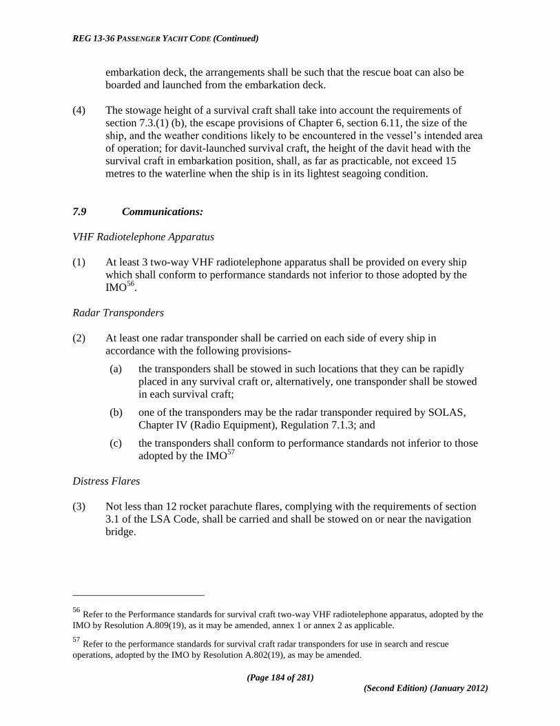
REG 13-36 PASSENGER YACHT CODE (Continued)
(Page 184 of 281)
(Second Edition) (January 2012)
embarkation deck, the arrangements shall be such that the rescue boat can also be
boarded and launched from the embarkation deck.
(4) The stowage height of a survival craft shall take into account the requirements of
section 7.3.(1) (b), the escape provisions of Chapter 6, section 6.11, the size of the
ship, and the weather conditions likely to be encountered in the vessel‘s intended area
of operation; for davit-launched survival craft, the height of the davit head with the
survival craft in embarkation position, shall, as far as practicable, not exceed 15
metres to the waterline when the ship is in its lightest seagoing condition.
7.9 Communications:
VHF Radiotelephone Apparatus
(1) At least 3 two-way VHF radiotelephone apparatus shall be provided on every ship
which shall conform to performance standards not inferior to those adopted by the
IMO56
.
Radar Transponders
(2) At least one radar transponder shall be carried on each side of every ship in
accordance with the following provisions-
(a) the transponders shall be stowed in such locations that they can be rapidly
placed in any survival craft or, alternatively, one transponder shall be stowed
in each survival craft;
(b) one of the transponders may be the radar transponder required by SOLAS,
Chapter IV (Radio Equipment), Regulation 7.1.3; and
(c) the transponders shall conform to performance standards not inferior to those
adopted by the IMO57
Distress Flares
(3) Not less than 12 rocket parachute flares, complying with the requirements of section
3.1 of the LSA Code, shall be carried and shall be stowed on or near the navigation
bridge.
56 Refer to the Performance standards for survival craft two-way VHF radiotelephone apparatus, adopted by the
IMO by Resolution A.809(19), as it may be amended, annex 1 or annex 2 as applicable.
57 Refer to the performance standards for survival craft radar transponders for use in search and rescue
operations, adopted by the IMO by Resolution A.802(19), as may be amended.
REG 13-36 PASSENGER YACHT CODE (Continued)
(Page 185 of 281)
(Second Edition) (January 2012)
On-board Communications and Alarm Systems
(4) An emergency means comprised of either fixed or portable equipment or both shall be
provided for two-way communications between emergency control stations, muster
and embarkation stations and strategic positions on board.
General Emergency Alarm
(5) A general emergency alarm system, complying with section 7.2.1 of the LSA Code
and with the following provisions, shall be provided on the navigation bridge and shall
be used for summoning passengers and crew to muster stations and to initiate the
actions included in the muster list-
(a) the system shall be supplemented by either a public address system or other
suitable means of communication;
(b) entertainment sound systems shall automatically be turned off when the
general emergency alarm system is activated;
(c) the general emergency alarm system shall be audible throughout the ship and
on all open decks; and
(d) on ships fitted with a marine evacuation system communication between the
embarkation station and the platform or the survival craft shall be ensured.
Public Address System
(6) All ships shall be fitted with a public address system which shall-
(a) be clearly audible above the ambient noise in all spaces, as prescribed by
paragraph 7.2.2.1 of the LSA Code;
(b) be provided with an override function controlled from one location on the
navigation bridge and such other places on board as the Administration deems
necessary, so that all emergency messages will be broadcast if any loudspeaker
in the spaces concerned has been switched off, its volume has been turned
down or the public address system is used for other purposes;
(c) have at least two loops which shall be sufficiently separated throughout their
length and have two separate and independent amplifiers;
(d) be connected to the emergency source of electrical power required by
Regulation 42.2.2 of Chapter II-1, Part D, of SOLAS; and
(e) be approved by the Administration having regard to the recommendations
adopted by the IMO58
.
58 Refer to MSC/Circ.808, Recommendation on performance standards for public address systems on passenger
ships, including cabling.

REG 13-36 PASSENGER YACHT CODE (Continued)
(Page 186 of 281)
(Second Edition) (January 2012)
7.10 Personal Life Saving Appliances:
Lifebuoys
(1) Ships shall carry not less than the number of lifebuoys prescribed in the following
table-
LIFEBUOYS AND ATTACHMENTS TO BE
CARRIED
GROSS TONNAGE OF SHIP
Under 3000 3000-10000 Over 10000
Total Minimum Number of Lifebuoys. 8 12 18 Minimum number of lifebuoys to be fitted
with self-igniting lights 6 6 9
Minimum number of lifebuoys provided
with self-igniting lights and self-
activating smoke signals. 2 2 2
Minimum number of Lifebuoys to be
provided with buoyant line. 2 2 2
(2) Lifebuoys which are fitted with self-igniting lights or with self-igniting lights and self-
activating smoke signals shall not also be fitted with a line.
(3) The lifebuoys fitted with self-igniting lights and with self-activating smoke signals
shall capable of quick release from the navigation bridge.
(4) At least one lifebuoy on each side of the ship shall be fitted with a buoyant lifeline
complying with the requirements of paragraph 2.1.4 of the LSA Code equal in length
to not less than twice the height at which it is stowed above the waterline in the
lightest seagoing condition, or 30 metres, whichever is the greater.
(5) Lifebuoys shall be-
(a) so distributed as to be readily available on both sides of the ship and as far as
practicable on all open decks extending to the ship's side; at least one shall be
placed in the vicinity of the stern; and
(b) so stowed as to be capable of being rapidly cast loose, and not permanently
secured in any way.
(6) Each lifebuoy shall be marked in block capitals of the Roman alphabet with the name
and port of registry of the ship on which it is carried.
Lifejackets
(7) A lifejacket complying with the requirements of paragraph 2.2.1 or 2.2.2 of the LSA
Code shall be provided for every person on board the ship and, in addition-
(a) a number of lifejackets suitable for children equal to at least 10% of the
number of passengers on board shall be provided or such greater number as
may be required to provide a lifejacket for each child;

REG 13-36 PASSENGER YACHT CODE (Continued)
(Page 187 of 281)
(Second Edition) (January 2012)
(b) a sufficient number of lifejackets shall be carried for persons on watch and for
use at remotely located survival craft stations and the lifejackets carried for
persons on watch should be stowed on the bridge, in the engine control room
and at any other manned watch station, as the case may be;
(c) infant lifejackets shall be provided for each infant on board;
(d) each lifejacket shall be fitted with a light and whistle according to the
requirements of section 2.2 of the LSA Code; and
(e) if the adult lifejackets provided are not designed to fit persons weighing up to
140 kg and with a chest girth of up to 1,750 millimetres, a sufficient number of
suitable accessories shall be available on board to allow them to be secured to
such person59
.
(8) In addition to the lifejackets required by subsection (7) an additional number of
lifejackets for not less than 5% of the total number of persons on board shall be carried
and these lifejackets shall be stowed in conspicuous places on deck or at muster
stations.
(9) Lifejackets shall be so placed as to be readily accessible and their position shall be
plainly indicated and where, due to the particular arrangements of the ship, the
lifejackets provided in compliance with the requirements of subsection (7) may
become inaccessible, alternative provisions shall be made to the satisfaction of the
Administration which may include an increase in the number of lifejackets to be
carried.
(10) Where lifejackets for passengers are stowed in staterooms which are located remotely
from direct routes between public spaces and muster stations, the additional lifejackets
for these passengers required under subsection (9), shall be stowed either in the public
spaces, the muster stations, or on direct routes between them provided that lifejackets
shall be stowed so that their distribution and donning does not impede orderly
movement to muster stations and survival craft embarkation stations.
(11) The lifejackets used in totally enclosed lifeboats shall not impede entry into the
lifeboat or seating, including operation of the seat belts in the lifeboat.
Immersion Suits and anti-Exposure Suits
(12) For a Passenger Yacht 1 an immersion suit60
or an anti-exposure suit, of an
appropriate size shall be provided for every person on board.
59 See Resolution MSC.207(81) - Adoption of Amendments to the International Life-Saving Appliance (LSA)
Code - (Adopted on 18 May 2006).
60 Unapproved immersion suits are permitted for children and infants.

REG 13-36 PASSENGER YACHT CODE (Continued)
(Page 188 of 281)
(Second Edition) (January 2012)
(13) For ships other than a Passenger Yacht 2 which do not carry partially or totally
enclosed lifeboats an immersion suit56
, of an appropriate size, shall be provided for
every person on board.
(14) Immersion suits shall be so placed as to be readily accessible and their position shall
be plainly indicated.
7.11 Muster List and Emergency Instructions:
(1) Clear instructions on the procedures to be followed in the event of an emergency shall
be provided for every person on board and these instructions shall be drawn up in the
language or languages required by the ship‘s flag State and in the English language.
(2) Muster lists and emergency instructions complying with the requirements of this
section shall be exhibited in conspicuous places throughout the ship including the
navigation bridge, engine-room and crew accommodation spaces.
(3) Illustrations and instructions in appropriate languages shall be available in passenger
cabins and be conspicuously displayed at muster stations and other passenger spaces
to inform passengers of-
(a) their muster station;
(b) the essential actions they must take in an emergency; and
(c) the method of donning lifejackets.
(4) The muster list shall specify-
(a) details of the general emergency alarm and public address system prescribed
by sections 7.9(5) and (6);
(b) the action to be taken by crew and passengers when this alarm is sounded; and
(c) how the order to abandon ship will be given.
(5) There shall be in place procedures in place for locating and rescuing passengers
trapped in their staterooms
(6) The muster list shall show the duties assigned to the different members of the crew
including-
(a) closing of the watertight doors, fire doors, valves, scuppers, sidescuttles,
skylights, portholes and other similar openings in the ship;
(b) equipping of the survival craft and other life-saving appliances;
(c) preparation and launching of survival craft;
(d) general preparation of other life-saving appliances;
(e) muster of passengers;

REG 13-36 PASSENGER YACHT CODE (Continued)
(Page 189 of 281)
(Second Edition) (January 2012)
(f) use of communication equipment;
(g) manning of fire parties assigned to deal with fires; and
(h) special duties assigned in respect to the use of fire-fighting equipment and
installations.
(7) The muster list shall also specify-
(a) which officers are assigned to ensure that life-saving and fire appliances are
maintained in good condition and are ready for immediate use;
(b) substitutes for key persons who may become disabled, taking into account that
different emergencies may call for different actions; and
(c) the duties assigned to members of the crew in relation to passengers in case of
emergency, which duties shall include-
(i) warning the passengers;
(ii) seeing that they are suitably clad and have donned their lifejackets
correctly;
(iii) assembling passengers at muster stations;
(iv) keeping order in the passageways and on the stairways and
generally controlling the movements of the passengers; and
(v) ensuring that a supply of blankets is taken to the survival craft.
(8) The muster list shall be prepared before the ship proceeds to sea and if any changes in
the crew subsequently take place which necessitate an alteration in the muster list, the
master shall either revise the list or prepare a new list.
(9) The format of the muster list used on passenger ships shall be approved by the
Administration.
7.12 Operating Instructions:
Posters or signs shall be provided on or in the vicinity of survival craft and their launching
controls and shall-
(a) illustrate the purpose of controls and the procedures for operating the appliance
and give relevant instructions or warnings;
(b) be easily seen under emergency lighting conditions; and
(c) use symbols in accordance with the recommendations of the IMO61
61 Refer to Refer to the Symbols related to life-saving appliances and arrangements adopted by the IMO by
Resolution A.760(18), as amended by resolution MSC.82(70).

REG 13-36 PASSENGER YACHT CODE (Continued)
(Page 190 of 281)
(Second Edition) (January 2012)
7.13 Manning of Survival Craft and Supervision:
(1) There shall be a sufficient number of trained persons on board for mustering and
assisting untrained persons.
(2) There shall be a sufficient number of crew members, who may be deck officers or
other appropriately certificated crew members, on board for operating the survival
craft and launching arrangements required for abandonment by the total number of
persons on board.
(3) A deck officer or certificated person shall be placed in charge of each survival craft to
be used provided that the Administration, having due regard to the nature of the
voyage, the number of persons on board and the characteristics of the ship, may permit
persons practised in the handling and operation of liferafts to be placed in charge of
liferafts in lieu of persons qualified as above and in the case of lifeboats a second-in-
command shall also be nominated.
(4) The person in charge of each of the survival craft shall have a list of the survival craft
crew and shall ensure that the crew under his command are acquainted with their
duties and in the case of lifeboats the second-in-command shall also have a list of the
lifeboat crew.
(5) Every motorised survival craft shall have a person assigned who is capable of
operating the engine and carrying out minor adjustments.
(6) The master shall ensure the equitable distribution of appropriately certificated crew
members, referred to subsections (1), (2) and (3), among the ship's survival craft.
7.14 Survival Craft Muster Stations and Embarkation Arrangements:
(1) Lifeboats and liferafts for which approved launching appliances are required shall be
stowed as close to accommodation and service spaces as possible.
(2) Muster stations shall-
(a) be provided in the vicinity of and shall permit ready access to the embarkation
stations;
(b) have sufficient clear deck space to accommodate all persons (passengers and
crew) assigned to muster at that station, with at least 0.35 m2 per person; and
(c) have ample room for the marshalling and instruction of passengers.
(3) Muster and embarkation stations shall-
(a) be readily accessible from accommodation and work areas; and

REG 13-36 PASSENGER YACHT CODE (Continued)
(Page 191 of 281)
(Second Edition) (January 2012)
(b) be adequately illuminated by lighting supplied from the emergency source of
electrical power required by Regulation 42 or 43 of Chapter II-1, Part D, of
SOLAS, as appropriate.
(4) Alleyways, stairways and exits giving access to the muster and embarkation stations
shall be adequately lighted and such lighting shall also be capable of being supplied by
the emergency source of electrical power by Regulation 42 or 43 of Chapter II-1, Part
D, of SOLAS, as appropriate; also in addition to and as part of the markings required
under section 6.11(18) routes to muster stations shall be indicated with the muster
station symbol, intended for that purpose, in accordance with the recommendations of
the IMO62
.
(5) Davit-launched survival craft muster and embarkation stations shall be so arranged as
to enable stretcher cases to be placed in survival craft.
(6) Subject to subsections (7) and (8), an embarkation ladder complying with paragraph
6.1.6 of the LSA Code, extending, in a single length, from the deck to the waterline in
the lightest seagoing condition under unfavourable conditions of trim of up to 10° and
a list of up to 20° either, way shall be provided at each embarkation station or at every
two adjacent embarkation stations for survival craft launched down the side of the
ship.
(7) The Administration may permit such ladders to be replaced by approved devices to
afford access to the survival craft when waterborne, in which case there shall be at
least one embarkation ladder on each side of the ship.
(8) Where necessary, means shall be provided for bringing the davit-launched survival
craft against the ship's side and holding them alongside so that persons can be safely
embarked.
7.15 Launching Stations:
Launching stations shall be in such positions as to ensure safe launching having particular
regard to clearance from the propeller and steeply overhanging portions of the hull and so
that, as far as possible, survival craft, can be launched down the straight side of the ship. If
positioned forward, they shall be located abaft the collision bulkhead in a sheltered position
and, in this respect; the Administration shall give special consideration to the strength of the
launching appliance.
62
Refer to the Symbols related to life-saving appliances and arrangements adopted by the IMO by Resolution
A.760(18), as amended by MSC.82(80), and to the Guidelines for the evaluation, testing and application of low-
location lighting on passenger ships adopted by the IMO by Resolution A.752(18).

REG 13-36 PASSENGER YACHT CODE (Continued)
(Page 192 of 281)
(Second Edition) (January 2012)
7.16 Line Throwing Appliance:
A line-throwing appliance complying with the requirements of section 7.1 of the LSA Code
shall be provided.
7.17 Emergency Procedures, Training and Drills:
Duties, Musters and Briefings
(1) Every crew member with assigned emergency duties shall be familiar with these
duties before the voyage begins.
(2) On a ship engaged on a voyage where passengers are scheduled to be on board for
more than 24 hours, musters of the passengers shall take place within 24 hours after
their embarkation and passengers shall be instructed in the use of the lifejackets and
the action to take in an emergency.
(3) Subject to subsection (4), whenever new passengers embark, a passenger safety
briefing shall be given to the new passengers immediately before sailing, or
immediately after sailing, which shall include the following provisions-
(a) the briefing shall include the instructions required by sections 7.11 (1) and (3),
and shall be made personally by a trained member of the crew or by means of
an announcement, in one or more languages likely to be understood by the
passenger;
(b) the announcement shall be made on the ship's public address system, or by
other equivalent means likely to be heard at least by the passengers who have
not yet heard it during the voyage;
(c) the briefing may be included in the muster required by section 7.17(2) if the
muster is held immediately upon departure; and
(d) information cards or posters or video programmes displayed on the ship‘s
video displays may be used to supplement the briefing, but may not be used to
replace the announcement.
(4) The briefings referred to in subsection (3) may be delivered using alternative
communication methods of conveying the required information provided that such
alternative is at least as effective.
Emergency Drills
(5) Drills shall, as far as practicable, be conducted as if there were an actual emergency.
(6) Every crew member shall participate in at least one abandon ship drill and one fire
drill every month and-

REG 13-36 PASSENGER YACHT CODE (Continued)
(Page 193 of 281)
(Second Edition) (January 2012)
(a) where more than 25% of the crew have not participated in abandon ship and
fire drills on board that particular ship in the previous month the drills of the
crew shall take place within 24 hours of the ship leaving a port;
(b) where a ship enters service for the first time, after modification of a major
character or when a new crew is engaged, the drills shall be held before the
vessel sails,
provided that the Administration may accept other arrangements that are at least
equivalent where this is impracticable.
(7) Each abandon ship drill shall include-
(a) summoning of passengers and crew to muster stations with the general
emergency alarm followed by drill announcement on the public address or
other communication system and ensuring that they are made aware of the
order to abandon ship;
(b) reporting to stations and preparing for the duties described in the muster list;
(c) checking that passengers and crew are suitably dressed;
(d) checking that lifejackets are correctly donned;
(e) lowering of at least one lifeboat after any necessary preparation for launching;
(f) starting and operating the lifeboat engine;
(g) operation of davits used for launching liferafts;
(h) a mock search and rescue of passengers trapped in their staterooms; and
(i) instruction in the use of radio life-saving appliances.
(8) Different lifeboats shall, as far as practicable, be lowered in compliance with the
requirements of subsection(7), paragraph (e), at successive drills.
(9) Except as provided in subsections (10), each lifeboat shall be launched, and
manoeuvred in the water by its assigned operating crew, at least once every three
months during an abandon ship drill.
(10) The Administration may allow ships operating on short international voyages not to
launch the lifeboats on one side if their berthing arrangements in port and their trading
patterns do not permit launching of lifeboats on that side provided that all such
lifeboats shall be lowered at least once every three months and launched at least
annually.
(11) As far as is reasonable and practicable, rescue boats other than lifeboats which are also
rescue boats, shall be launched each month with their assigned crew aboard and
manoeuvred in the water and in any case this requirement shall be complied with at
least once every three months.

REG 13-36 PASSENGER YACHT CODE (Continued)
(Page 194 of 281)
(Second Edition) (January 2012)
(12) If lifeboat and rescue boat launching drills are carried out with the ship making
headway, such drills shall, because of the dangers involved, be practiced in sheltered
waters only and under the supervision of an officer experienced in such drills63
.
(13) If a ship is fitted with marine evacuation systems-
(a) drills shall include exercising of the procedures required for the deployment of
such a system up to the point immediately preceding actual deployment;
(b) this aspect of drills should be augmented by regular instruction using the on-
board training aids in the use of the system; and
(c) every system party member shall, as far as practicable, be further trained by
participation in a full deployment of a similar system into water, either on
board a ship or ashore, at intervals of not longer than three years; provided that
this training can be associated with the rotational deployments required by
section 7.20(17).
(14) Emergency lighting for mustering and abandonment shall be tested at each abandon
ship drill.
Fire Drills
(15) Fire drills should be planned in such a way that due consideration is given to regular
practice in the various emergencies that may occur.
(16) Each fire drill shall include-
(a) reporting to stations and preparing for the duties described in the muster list
required by section 7.11;
(b) starting of a fire pump, using at least the two required jets of water to show that
the system is in proper working order;
(c) checking of fireman's outfit and other personal rescue equipment;
(d) checking of relevant communication equipment;
(e) checking the operation of watertight doors, fire doors, fire dampers and main
inlets and outlets of ventilation systems in the drill area; and
(f) checking the necessary arrangements for subsequent abandoning of the ship.
(17) The equipment used during drills shall immediately be brought back to its fully
operational condition and any faults and defects discovered during the drills shall be
remedied as soon as possible.
63
Refer to the Guidelines on training for the purpose of launching lifeboats and rescue boats from ships making
headway through the water adopted by the IMO by Resolution A.624(15).

REG 13-36 PASSENGER YACHT CODE (Continued)
(Page 195 of 281)
(Second Edition) (January 2012)
On-board Training and Instructions
(18) On-board training in the use of the ship's life-saving appliances, including survival
craft equipment, and in the use of the ship's fire-extinguishing appliances shall-
(a) subject to paragraph (b), be given as soon as possible but not later than two
weeks after a crew member joins the ship;
(b) if the crew member is on a regularly scheduled rotating assignment to the ship,
such training shall be given not later than two weeks after the time of first
joining the ship;
(c) include instructions in the use of the ship's fire-extinguishing appliances, life-
saving appliances, and in survival at sea, which shall be given at the same
interval as the drills;
(d) Incorporate individual instruction covering different parts of the ship's life-
saving and fire-extinguishing appliances, such that all the ship's life-saving and
fire-extinguishing appliances shall be covered within any period of two
months.
(19) Every crew member shall be given instructions which shall include but not necessarily
be limited to-
(a) the operation and use of the ship's inflatable liferafts;
(b) the problems of hypothermia, first-aid treatment for hypothermia and other
appropriate first-aid procedures;
(c) any special instructions necessary for use of the ship's life-saving appliances in
severe weather and severe sea conditions; and
(d) the operation and use of fire-extinguishing appliances.
(20) On-board training in the use of davit-launched liferafts shall take place at intervals of
not more than three months on every ship fitted with such appliances. Whenever
practicable this shall include the inflation and lowering of a liferaft. This liferaft may
be a special liferaft intended for training purposes only, which is not part of the ship's
life-saving equipment; such a special liferaft shall be conspicuously marked.
Records
(21) The date when musters are held, details of abandon ship drills and fire drills, drills of
other life-saving appliances and on board training shall be recorded in such log-book
as may be prescribed by the Administration; provided that if a full muster, drill or
training session is not held at the appointed time, an entry shall be made in the log-
book stating the circumstances and the extent of the muster, drill or training session
held.

REG 13-36 PASSENGER YACHT CODE (Continued)
(Page 196 of 281)
(Second Edition) (January 2012)
7.18 Frequency of Drills and Involvement of Crew and Passenger:
(1) An abandon ship drill and fire drill shall take place weekly.
(2) The entire crew need not be involved in every drill, but each crew member must
participate in an abandon ship drill and a fire drill each month.
(3) Passengers shall be strongly encouraged to attend these drills.
7.19 Training Manual and On-board Training Aids:
(1) A training manual complying with the requirements contained in subsections (2) to (4)
shall be provided in each crew mess room and recreation room or in each crew cabin.
(2) Subject to subsection (3), the training manual, which may comprise several volumes,
shall contain instructions and information, in easily understood terms, illustrated
wherever possible, on the life-saving appliances provided in the ship and on the best
methods of survival.
(3) Any part of such information as is contained in the manual may be provided in the
form of audio-visual aids in lieu of the manual.
(4) The following shall be explained in detail in the manual or through the audio-visual
aids, as the case may be-
(a) donning of lifejackets, immersion suits and anti-exposure suits, as appropriate;
(b) muster at the assigned stations;
(c) boarding, launching, and clearing the survival craft and rescue boats,
including, where applicable, use of marine evacuation systems;
(d) method of launching from within the survival craft;
(e) release from launching appliances;
(f) methods and use of devices for protection in launching areas, where
appropriate;
(g) illumination in launching areas;
(h) use of all survival equipment;
(i) use of all detection equipment;
(j) with the assistance of illustrations, the use of radio lifesaving appliances;
(k) use of drogues;
(l) use of engine and accessories;
(m) recovery of survival craft and rescue boats including stowage and securing;

REG 13-36 PASSENGER YACHT CODE (Continued)
(Page 197 of 281)
(Second Edition) (January 2012)
(n) hazards of exposure and the need for warm clothing;
(o) best use of the survival craft facilities in order to survive;
(p) methods of retrieval, including the use of helicopter rescue gear (slings,
baskets, stretchers), breeches-buoy and shore life-saving apparatus and ship‘s
line-throwing apparatus;
(q) all other functions contained in the muster list and emergency instructions; and
(r) instructions for emergency repair of the life-saving appliances.
(5) Every ship fitted with a marine evacuation system shall be provided with on-board
training aids in the use of the system.
(6) The training manual shall be written in English and, where the working language of
the crew is not English, in such working language as appropriate.
7.20 Operational Readiness, Maintenance and Inspection:
Operational Readiness
(1) Before the ship leaves port and at all times during the voyage, all life-saving
appliances shall be in working order and ready for immediate use.
Maintenance of Life Saving Appliances
(2) Maintenance, testing and inspections of life–saving appliances shall be carried out
based on the guidelines developed by the IMO64
and in a manner having due regard to
ensuring reliability of such appliances.
(3) Instructions for on-board maintenance of life-saving appliances complying with
subsection (16) shall be provided and maintenance shall be carried out accordingly.
(4) The Administration may accept, in compliance with the requirements of subsection
(3), a shipboard planned maintenance programme, which includes the items covered in
the list required in accordance with subsection (16).
Maintenance of Falls
(5) Falls used in launching shall be inspected periodically65
with special regard for areas
passing through sheaves, and renewed when necessary due to deterioration of the falls
or at intervals of not more than 5 years, whichever is the earlier.
64
Refer to the Guidelines for periodic servicing and maintenance of lifeboats, launching appliances and on-load
release gear (MSC/Circ.1093).
65 Refer to Measures to prevent accidents with lifeboats (MSC.1/Circ.1206).

REG 13-36 PASSENGER YACHT CODE (Continued)
(Page 198 of 281)
(Second Edition) (January 2012)
Spares and Repair Equipment
(6) Spares and repair equipment shall be provided for life-saving appliances and their
components which are subject to excessive wear or consumption and need to be
replaced regularly.
Weekly Tests and Inspections
(7) The following tests and inspections shall be carried out weekly and a report on them
shall be entered in the log-book-
(a) all survival craft, rescue boats and launching appliances shall be visually
inspected to ensure that they are ready for use and the inspection shall include,
but not be limited to, the condition of hooks, their attachment to the lifeboat
and the confirmation that the on-load release gear has been properly and
completely reset;
(b) all engines in lifeboats and rescue boats shall be run for a total period of not
less than 3 minutes, provided the ambient temperature is above the minimum
temperature required for starting and running the engine and during this period
of time it should be demonstrated that the gear box and gear box train are
engaging satisfactorily;
(c) if the special characteristics of an outboard motor fitted to a rescue boat would
not allow it to be run for a period of 3 minutes other than with its propeller
submerged, a suitable water supply may be provided; and
(d) the general emergency alarm shall be tested.
Monthly Tests and Inspections
(8) The following tests and inspections shall be carried out monthly and a report on them
shall be entered in the log-book-
(a) all lifeboats, except free-fall lifeboats, shall be turned out from their stowed
position, without any persons on board, if weather and sea conditions so allow;
and
(b) inspection of the life-saving appliances, including lifeboat equipment, shall be
carried out using the checklist required by subsection (16) to ensure that they
are complete and in good order.
Servicing of Life Saving Appliances and Systems
(9) Every inflatable liferaft, inflatable lifejacket, marine evacuation system and inflated
rescue boat shall be serviced-
(a) at intervals not exceeding 12 months, provided where in any case this is
impracticable, the Administration may extend this period to 17 months; and

REG 13-36 PASSENGER YACHT CODE (Continued)
(Page 199 of 281)
(Second Edition) (January 2012)
(b) at an approved servicing station which is competent to service them, maintains
proper servicing facilities and uses only properly trained personnel66
.
(10) An Administration which approves new and novel inflatable liferaft arrangements
pursuant to section 7.2 may allow for extended service intervals on the following
conditions-
(a) the new and novel liferaft arrangement has proved to maintain the same
standard, as required by testing procedure, during extended service intervals.
(b) the liferaft system shall be checked on board by certified personnel at intervals
set out in subsection (9)(b).
(c) service at intervals not exceeding five years shall be carried out in accordance
with the recommendations of the IMO67.
(11) An Administration which permits extension of liferaft service intervals in accordance
with subsection (10) shall notify the IMO of such action in accordance with
Regulation 5(b) of Chapter I of SOLAS.
(12) All repairs and maintenance of inflated rescue boats shall be carried out in accordance
with the manufacturer‘s instructions; emergency repairs may be carried out on board
the ship; however, permanent repairs shall be effected at an approved servicing
station.
Servicing of Life Saving Appliances and Systems
(13) Hydrostatic release units, other than disposable hydrostatic release units, shall be
serviced-
(a) at intervals not exceeding 12 months, provided where in any case this is
impracticable, the Administration may extend this period to 17 months68;
and
(b) at a servicing station which is competent to service them, maintains proper
servicing facilities and uses only properly trained personnel.
Periodic Servicing of Launching Appliances and on-Load Release Gear
(14) Launching appliances shall be-
66
Refer to the Recommendation on conditions for the approval of servicing stations for inflatable liferafts,
adopted by the IMO by Resolution A.761(18).
67 Refer to the Recommendation on conditions for the approval of servicing stations for inflatable liferafts,
adopted by the IMO by Resolution A.761(18). Account should also be taken of the service period for the
equipment recommended by the manufacturer.
68 Refer to MSC/Circ.955, Servicing of life-saving appliances and Radiocommunication equipment under the
harmonized system of survey and certification (HSSC).

REG 13-36 PASSENGER YACHT CODE (Continued)
(Page 200 of 281)
(Second Edition) (January 2012)
(a) maintained in accordance with instructions for on-board maintenance as
required by subsection (16).
(b) subject to a thorough examination at the annual surveys required by
Regulations 7 or 8 of Chapter I of SOLAS, as applicable; and
(c) upon completion of the examination referred to in paragraph (b) above,
subjected to a dynamic test of the winch brake at maximum lowering speed
and the load to be applied shall be the mass of the survival craft or rescue boat
without persons on board, provided that, at intervals not exceeding five years,
the test shall be carried out with a proof load equal to 1.1 times the weight of
the survival craft or rescue boat and its full complement of persons and
equipment.
(15) Lifeboat or rescue boat on-load release gear shall be-
(a) maintained in accordance with instructions for on-board maintenance as
required by subsection (16);
(b) subject to a thorough examination and operational test during the annual
surveys required by Regulations 7 or 8 of Chapter I of SOLAS, as applicable;
and
(c) operationally tested under a load of 1.1 times the total mass of the boat when
loaded with its full complement of persons and equipment whenever the
release gear is overhauled provided that such over-hauling and test shall be
carried out at least once every five years69
.
(16) Instructions for on-board maintenance of life-saving appliances shall be easily
understood, illustrated wherever possible, and, as appropriate, shall include the
following for each appliance-
(a) a checklist for use when carrying out the inspections required by subsection
(8)(b);
(b) maintenance and repair instructions;
(c) a schedule of periodic maintenance;
(d) a diagram of lubrication points with the recommended lubricants;
(e) a list of replaceable parts;
(f) a list of sources of spare parts; and
(g) a log for records of inspections and maintenance.
69
Refer to the Recommendation on testing of life-saving appliances, adopted by the IMO by resolution
A.689(17). For life-saving appliances installed on board on or after 1 July 1999, refer to the Revised
Recommendations on testing of life-saving appliances, adopted by the IMO by resolution MSC.81(70).

REG 13-36 PASSENGER YACHT CODE (Continued)
(Page 201 of 281)
(Second Edition) (January 2012)
Rotational Deployment of Marine Evacuation Systems
(17) In addition to or in conjunction with the servicing intervals of marine evacuation
systems required by subsection (9), each marine evacuation system should be
deployed from the ship on a rotational basis at intervals to be agreed by the
Administration provided that each system is to be deployed at least once every six
years.
Marking of Stowage Locations
(18) Containers, brackets, racks, and other similar stowage locations for life-saving
equipment, shall be marked with symbols in accordance with the recommendations of
the IMO70
, indicating the devices stowed in that location for that purpose and where
more than one device is stowed in that location, the number of devices shall also be
indicated.
7.21 Survival Craft and Rescue Boats to be Carried:
Survival Craft
(1) A Passenger Yacht 1 which does not comply with the enhanced survivability standards
of Part VII of Chapter 4 of the Code shall carry-
(a) subject to subparagraph 7.21(1)(b), partially or totally enclosed lifeboats on
each side of such aggregate capacity as will accommodate not less than 50% of
the total number of persons on board;
(b) the Administration may permit the substitution of lifeboats by liferafts of
equivalent total capacity provided that there shall never be less than sufficient
lifeboats on each side of the ship to accommodate 37.5% of the total number of
persons on board;
(c) the inflatable or rigid liferafts shall be served by launching appliances equally
distributed on each side of the ship; and
(d) in addition, inflatable or rigid liferafts of such aggregate capacity as will
accommodate at least 25% of the total number of persons on board;
(e) the liferafts in subsection 7.21(1)(d) shall be served by at least one launching
appliance on each side which may be those provided in compliance with the
requirements of subsection 7.21(1)(c) or equivalent approved appliances
capable of being used on both sides.
(2) Passenger Yachts to which this Code applies, other than those referred to in subsection
(1), shall carry survival craft in accordance with Table 7.1 below-
70
Refer to the Symbols related to life-saving appliances and arrangements, adopted by the IMO by Resolution
A.760(18).

REG 13-36 PASSENGER YACHT CODE (Continued)
(Page 202 of 281)
(Second Edition) (January 2012)
TABLE 7-1
SCALE OF SURVIVAL CRAFT TO BE CARRIED BY VESSELS TO WHICH THIS CODE
APPLIES AND RELATED DAMAGED STABILITY AND SURVIVABILITY STANDARDS
APPLICABLE
CATEGORY
OF
PASSENGER
YACHT
OPERATIONAL
AREA
DAMAGED
STABILITY
STANDARDS
APPLICABLE71 ENHANCED
SURVIVABILITY72
LSA (SURVIVAL CRAFT) SCALE73
MA
XIM
UM
PE
RS
ON
S
<80 M ≥80 M <80 M ≥80 M <80 M AND
>500 GT
Pleasure Vessel not Engaged in
Trade
Unlimited74
D --- 300%
DLLR & MES
99
P --- 300%
DLLR & MES
99
Passenger Yacht
Unrestricted (Engaged in
Trade)
Unlimited
D 2 Compartment
Enhanced.
300% DLLR &
MES 99
P 2 Compartment
Enhanced.
300% DLLR &
MES 50
Passenger Yacht
Unrestricted (Engaged in
Trade)75
Short International
Voyages
As per SOLAS Chapter II-1 Part B
Not Applicable
As per SOLAS Chapter
III
<200
PY-1
Prescribed International
Voyage (As defined in section 1.3)
D 2 Compartment
Enhanced. 300% DLLR &
MES 99
P 2 Compartment
Enhanced. 300% DLLR &
MES 99
PY-2 PY2 Area is as
defined in section 1.3.76
D --- 300% DLLR &
MES 99
P --- 300% DLLR &
MES 99
(3) For vessels carrying Davit Launched Life Rafts (DLLRs) or a combination of DLLRs
and Marine Evacuation Systems (MESs) the following shall apply-
71 D = Deterministic method. P = Probabilistic method. 72
2 Compartment Enhanced Survivability as set out in Chapter 4, Part VII of the Code. 73
The survival craft are to be distributed at 150% each side of the vessel. 74
Unlimited Area does not include the Polar Regions. Any passenger yacht operating in the Polar Regions is
required to carry Lifeboats as per SOLAS requirements and shall also adhere, inter alia, to the IMO
Guidelines for Polar Regions. 75
This is a SOLAS passenger ship engaged on Short International Voyages to which the Code does not apply
and the category is included for information only. See SOLAS Chapter III, Part B-2, Regulation 21. 76 Engaged on voyages in wind and weather conditions not exceeding Wind Scale 6 and Sea State 5 on the
Beaufort scale and during which the ship is not more than 20 nautical miles from land and not more than 60
nautical miles from a port or place in which the passengers and crew could be placed in safety.

REG 13-36 PASSENGER YACHT CODE (Continued)
(Page 203 of 281)
(Second Edition) (January 2012)
(a) MESs are not permitted as the sole means of abandonment and in this regard
the aggregate capacity of DLLRs each side of the ship shall be sufficient for
not less than 100% of the total persons on board;
(b) in the event of the loss of any one survival craft there shall be at least 100%
capacity remaining on either side; and
(c) in all cases dry shod evacuation shall be required.
(4) Any Passenger Yacht to which this Code applies which operates in the Polar Regions
shall carry lifeboats and other survival craft in accordance with the relevant SOLAS
requirements and shall, inter alia, also adhere to the IMO Guidelines for Polar
Regions.
(5) A passenger Yacht of less than 500 gross tonnage which carries less than 200 persons
may, under SOLAS Chapter III, Part B, Section II, Regulation 21.1-1.4, carry 300%
(150% each side) inflatable or rigid liferafts complying with sections 4.2 or 4.3 of
Chapter IV of the LSA Code providing other applicable provisions of the relevant
Conventions are complied with.
Rescue Boats
(6) Ships of 500 gross tonnage and over shall carry at least one rescue boat on each side of
the ship.
(7) Ships of less than 500 gross tonnage shall carry at least one rescue boat.
(8) A lifeboat may be accepted as a rescue boat provided it also complies with the
requirements for a rescue boat.
7.22 Time to Launch Survival Craft:
All survival craft required to provide for abandonment by the total number of persons on
board shall be capable of being launched with their full complement of persons and
equipment within a period of 30 minutes from the time the abandon ship signal is given and
after all persons have been assembled, with lifejackets donned.
7.23 Marshalling of Liferafts:
The number of lifeboats and rescue boats that are carried on ships shall be sufficient to ensure
that in providing for abandonment by the total number of persons on board not more than six
liferafts need be marshalled by each lifeboat or rescue boat.

REG 13-36 PASSENGER YACHT CODE (Continued)
(Page 204 of 281)
(Second Edition) (January 2012)
7.24 Decision Support System for Masters:
(1) All ships shall be provided with a decision support system for emergency management
on the navigation bridge.
(2) The system shall, as a minimum, consist of a printed emergency plan or plans77
. All
foreseeable emergency situations shall be identified in the emergency plan or plans,
including, but not limited to, the following main groups of emergencies-
(a) fire;
(b) damage to ship;
(c) pollution;
(d) unlawful acts threatening the safety of the ship and the security of its
passengers and crew;
(e) personnel accidents; and
(f) emergency assistance to other ships.
(3) The emergency procedures established in the emergency plan or plans shall provide
decision support to masters for handling any combination of emergency situations.
(4) The emergency plan or plans shall have a uniform structure and be easy to use.
(5) Where applicable, the actual loading condition as calculated for the ship's voyage
stability shall be used for damage control purposes.
(6) In addition to the printed emergency plan or plans, the Administration may also accept
the use of a computer-based decision support system on the navigation bridge which
provides all the information contained in the emergency plan or plans, procedures,
checklists, etc., which is able to present a list of recommended actions to be carried
out in foreseeable emergencies.
7.25 Information on Passengers:
(1) Every ship shall have in place a system for counting all persons on board prior to
departure. The system for counting all persons on board shall be approved by the
Administration.
(2) Details of persons who have declared a need for special care or assistance in
emergency situations shall be recorded and communicated to the master prior to
departure.
77
Refer to the Guidelines for a structure of an integrated system of contingency planning for shipboard
emergencies adopted by the IMO by resolution A.852(20).

REG 13-36 PASSENGER YACHT CODE (Continued)
(Page 205 of 281)
(Second Edition) (January 2012)
(3) In addition, the names and gender of all persons on board, distinguishing between
adults, children and infants shall be recorded for search and rescue purposes.
(4) The information required by this section shall be kept ashore and made readily
available to search and rescue services when needed.
7.26 Alternative Design and Arrangements: (38 – New Amendments)
Purpose
(1) The purpose of this section is to provide a methodology for the assessment and
acceptance of alternative design and arrangements for life saving appliances.
General
(2) Life-saving appliances and arrangements may deviate from the requirements set out in
this Chapter, provided that the alternative design and arrangements meet the intent of
the requirements concerned and provide an equivalent level of safety to Chapter III of
SOLAS.
(3) When alternative design or arrangements deviate from the prescriptive requirements of
this Chapter, an engineering analysis, evaluation and approval of the design and
arrangements shall be carried out.
Engineering Analysis
(4) The engineering analysis shall be prepared and submitted to the Administration, based
on the guidelines developed by the IMO17
and shall include, as a minimum, the
following elements-
(a) determination of the ship type and the life-saving appliance and arrangements
concerned;
(b) identification of the prescriptive requirement(s) with which the life-saving
appliance and arrangements will not comply;
(c) identification of the reason the proposed design will not meet the prescriptive
requirements supported by compliance with other recognised engineering or
industry standards;
(d) determination of the performance criteria for the ship and the life-saving
appliance and arrangements concerned addressed by the relevant prescriptive
requirement(s)-
(i) performance criteria shall provide a level of safety not inferior to
the relevant prescriptive requirements contained in this Chapter;
and
(ii) performance criteria shall be quantifiable and measurable;
REG 13-36 PASSENGER YACHT CODE (Continued)
(Page 206 of 281)
(Second Edition) (January 2012)
(e) detailed description of the alternative design and arrangements, including a list
of the assumptions used in the design and any proposed operational restrictions
or conditions;
(f) technical justification demonstrating that the alternative design and
arrangements meet the safety performance criteria; and
(g) risk assessment based on identification of the potential faults and hazards
associated with the proposal.
Evaluation of the Alternative Design and Arrangements
(5) The engineering analysis required by subsection (4) shall be evaluated and approved
by the Administration, taking into account the guidelines developed by the IMO78
.
(6) A copy of the documentation, as approved by the Administration, indicating that the
alternative design and arrangements comply with this paragraph, shall be carried on
board the ship.
Exchange of Information
(7) The Administration shall communicate to the IMO pertinent information concerning
alternative design and arrangements approved by them for circulation to all
Contracting Governments.
Re-evaluation due to Change of Conditions
(8) If the assumptions and operational restrictions that were stipulated in the alternative
design and arrangements are changed, the engineering analysis shall be carried out
under the changed condition and shall be approved by the Administration.
78
Refer to the guidelines on alternative design and arrangements for SOLAS Chapter II-1 and III
(MSC.1/Circ.1212).
REG 13-36 PASSENGER YACHT CODE (Continued)
(Page 207 of 281)
(Second Edition) (January 2012)
CHAPTER 8
RADIOCOMMUNICATIONS, SAFETY OF NAVIGATION, INTERNATIONAL SAFETY
MANAGEMENT AND MARITIME SECURITY
8.1 Radiocommunications:
Every ship to which this Code applies shall comply with the applicable requirements of
Chapter IV of SOLAS, 1974, as amended.
8.2 Safety of Navigation:
Subject to any special provisions given in the national legislation every ship to which this
Code applies shall comply with the applicable requirements of Chapter V of SOLAS, 1974, as
amended.
8.3 International Safety Management:
Every ship to which this Code applies shall comply with the applicable requirements of
Chapter IX of SOLAS, 1974, as amended.
8.4 Maritime Security:
Every ship to which this Code apples shall comply with the applicable requirements of
Chapter XI-2 of SOLAS, 1974, as amended, regarding Special Measures to Enhance
Maritime Security.

REG 13-36 PASSENGER YACHT CODE (Continued)
(Page 208 of 281)
(Second Edition) (January 2012)
This page is intentionally added to achieve correct pagination.

REG 13-36 PASSENGER YACHT CODE (Continued)
(Page 209 of 281)
(Second Edition) (January 2012)
Chapter 9
ACCOMMODATION AND RECREATIONAL FACILITIES-DESIGN AND
CONSTRUCTION:
9.1 General Requirements for Living Accommodation:
(1) A decent standard of accommodation and recreational facilities shall be provided and
maintained to ensure the comfort, recreation, well being and health and safety for
seafarers working or living on board.
(2) For the purposes of this Chapter, account may be taken of any provisions agreed to be
substantially equivalent by member states applying this Code, in accordance with the
requirements of Article VI/4 of the Maritime Labour Convention, 2006.
(3) Accommodation, recreational and catering facilities shall meet the requirements of
this Chapter and the related provisions in this Code, on health and safety protection
and accident prevention, with respect to preventing the risk of exposure to hazardous
levels of noise and vibration and other ambient factors and chemicals on board ships
and to provide an acceptable occupational and on-board living environment for
seafarers.
(4) There shall be adequate headroom in all seafarer accommodation and the minimum
permitted headroom in all seafarer accommodation where full and free movement is
necessary shall be not less than 203 centimetres; provided that the Administration
may permit some limited reduction in headroom in any space, or part of any space, in
such accommodation where it is satisfied that the accommodation complies with
subsection (1) and that such reduction-
(a) is reasonable; and
(b) does not result in discomfort to the seafarer.
(4) The accommodation shall be-
(a) so situated, constructed, arranged and acoustically insulated79
as to exclude so
far as is reasonably practicable noise coming from ship‟s equipment,
machinery, working spaces and any part of the accommodation; and
(b) be adequately thermally insulated; and
(c) additionally comply with the provisions of section 9.21(3).
79
The limits for noise levels for working and living spaces should be in conformity with the ILO international
guidelines on exposure levels, including those in the ILO code of practice entitled Ambient factors in the
workplace, 2001, and, where applicable, the specific protection recommended by the International Maritime
IMO, and with any subsequent amending and supplementary instruments for acceptable noise levels on board
ships.

REG 13-36 PASSENGER YACHT CODE (Continued)
(Page 210 of 281)
(Second Edition) (January 2012)
(5) Wherever practicable the accommodation shall comply with the following
requirements-
(a) it shall be situated amidships or aft; but in no case shall any part of the crew
accommodation, except a store room, be situated forward of the collision
bulkhead; and
(b) the Administration may permit the location of sleeping rooms below the load
line provided that satisfactory arrangements are made for lighting and
ventilation, but in no case shall they be located immediately beneath working
alleyways.
(6) There shall be no direct openings into sleeping rooms from machinery spaces or from
galleys, storerooms, drying rooms or communal sanitary area and that part of a
bulkhead separating such places from sleeping rooms and external bulkheads shall be
efficiently constructed of steel or equivalent and be watertight and gas-tight.
(7) The materials used to construct internal bulkheads, panelling and sheeting, floors and
joining shall be suitable for the purpose and conducive to ensuring a healthy
environment.
9.2 External Bulkheads:
(1) Bulkheads which enclose any part of the crew accommodation and are exposed to the
weather shall be properly constructed of steel or other suitable material and-
(a) the bulkheads shall be of watertight construction and any openings in them
shall be provided with means of weathertight closure;
(b) the means of weathertight closure provided for any entrance shall be a hinged
door, except where agreed otherwise by the Administration and an equivalent
level of crew protection is provided;
(c) bulkheads which enclose any part of the crew accommodation and are exposed
to the weather, and any part of the side of the ship which forms a wall or part
of a wall of the crew accommodation; shall be so insulated as to prevent
overheating or condensation unless the crew accommodation is so protected
by its situation and ventilation that overheating and condensation are unlikely
to occur;
(d) all machinery casings and all boundary bulkheads of galleys and other spaces
in which heat is produced shall be adequately insulated where there is a
possibility of resulting heat effects in adjoining accommodation or
passageways; and
(e) every bulkhead, casing or deck separating any part of the crew
accommodation from any space (including a cold store room) which is subject

REG 13-36 PASSENGER YACHT CODE (Continued)
(Page 211 of 281)
(Second Edition) (January 2012)
to abnormal heat or cold shall be so insulated as to prevent condensation or
discomfort to the crew.
(2) Every bulkhead which separates any part of the crew accommodation (other than
recreation deck space) from a space used as-
(a) a machinery space;
(b) a garage space;
(c) a room for storing fire-extinguishing gases;
(d) a chain locker;
(e) a cofferdam;
(f) a store room;
(g) a paint room;
(h) a battery locker,
shall be of gastight construction, and shall be of watertight construction where
necessary to protect the crew accommodation.
(3) There shall be no opening in any of the bulkheads referred to in subsection 9.2(2)
subject to such special arrangements as may be permitted by the Administration.
(4) No batteries of a type which emit gases shall be stored in the crew accommodation
and there shall be no opening from the crew accommodation into a space where such
batteries are stored and precautions shall be taken to ensure that fumes from batteries
cannot be discharged into the crew accommodation.
(5) Any part of the crew accommodation which adjoins a tank in which oil may be carried
shall be separated from that tank by either-
(a) a gastight steel division additional to the division which retains the oil; or
(b) a division of all-welded steel construction capable of withstanding a head of
water at least 1.5 metres greater than the maximum service head.
(6) No manhole or other opening to a fuel tank shall be situated in the crew
accommodation.
9.3 Interior Bulkheads:
(1) All interior bulkheads within the crew accommodation shall be properly constructed
of steel or other suitable material.
(2) Sleeping rooms, mess rooms, recreation rooms and alleyways in the accommodation
space shall be adequately insulated to prevent condensation or overheating.

REG 13-36 PASSENGER YACHT CODE (Continued)
(Page 212 of 281)
(Second Edition) (January 2012)
(3) The bulkhead surfaces and deckheads shall be of material with a surface easily kept
clean and no form of construction likely to harbour vermin shall be used.
(4) The bulkhead surfaces and deckheads in sleeping rooms and mess rooms shall be
capable of being easily kept clean and light in colour with a durable, non-toxic finish.
(5) The decks in all seafarer accommodation shall be of approved material and
construction and shall provide a surface impervious to damp and easily kept clean.
(6) Where the floorings are of composite materials the joints with sides shall be profiled
to avoid crevices.
(7) Subject to subsection 9.3(8)-
(a) every bulkhead which separates any part of the crew accommodation from-
(i) sanitary accommodation;
(ii) a laundry;
(iii) a drying room;
(iv) a galley;
(v) a cold store room; and
(vi) a dry provision store room,
shall be of gastight construction; and
(b) every bulkhead which separates any part of the crew accommodation from any
of the spaces specified in paragraph (a) shall be watertight to a height of not
less than 230 millimetres, except in the case of doorways situated in bulkheads
when the bulkheads shall be watertight to a height of not less than 100
millimetres.
(8) The requirements of subsection 9.3(7) shall not apply to bulkheads separating-
(a) a space appropriated for a particular use from another space appropriated for
the same use;
(b) a laundry from a drying room; and
(c) a private bathroom from the sleeping room of the person for whose use it is
provided, if there is direct access from the sleeping room to the private
bathroom.
(9) Subject to the provisions of section 9.15 there shall be no openings in any bulkhead
separating any sanitary accommodation, laundry or drying room from any part of the
crew accommodation except a passageway, recreation deck space or other sanitary
accommodation, laundry or drying room; provided that en-suite facilities are excluded
from this provision.

REG 13-36 PASSENGER YACHT CODE (Continued)
(Page 213 of 281)
(Second Edition) (January 2012)
9.4 Overhead Decks:
Every deck which forms the crown of any part of the crew accommodation shall-
(a) be adequately insulated to prevent condensation and overheating;
(b) where it is exposed to the weather, be of such material and so constructed as to
prevent ingress of water; and
(c) be of adequate strength to support any weight which may be placed upon it.
9.5 Floor Decks:
(1) Every deck which forms the floor of any part of the crew accommodation (in this
regulation called a “floor deck”) shall-
(a) be properly constructed and if it is directly over an oil tank it shall be
constructed in accordance with the requirements of section 9.2(5);
(b) shall have a surface which provides a good foothold and can be easily kept
clean; and
(c) where one is provided, have a floor covering that is impervious to water and, if
the deck is directly over an oil tank, impervious to oil.
(2) Subject to subsection 9.5(3) every floor deck made of metal, except floor decks in
sanitary accommodation, galleys, laundries and store rooms, shall be covered with a
material suitable to its purpose and the material shall be properly laid and the joins
where the floor meets the walls shall be rounded in such a way as to avoid crevices.
(3) On every floor deck in crew accommodation, where a fitted carpet is laid it shall be
laid on a deck covering which is suitable for its purpose and the carpet shall be such
that it will not readily ignite.
(4) Every floor deck in sanitary accommodation, galleys and laundries shall be covered
with terrazzo, tiles or other hard material which is impervious to liquids and provides
a good foothold and the covering shall be properly laid and the joins where the floor
meets the walls shall be rounded in such a way as to avoid crevices.
9.6 Access and Escape Arrangements:
(1) Every entrance into the crew accommodation from the open deck shall be so situated
and constructed as to be protected against the weather and sea to the greatest extent
practicable and the entrances shall be so situated that the crew accommodation is
accessible at all times and in all weathers.

REG 13-36 PASSENGER YACHT CODE (Continued)
(Page 214 of 281)
(Second Edition) (January 2012)
(2) There shall be at least one means of access, either direct or via not more than two
rooms forming part of a suite, to any sleeping room, day room, mess room, recreation
room, study, office, sanitary accommodation or galley, from an enclosed passageway.
(3) Two entirely separate escape routes shall be provided for each compartment,
complying with the following provisions-
(a) the escape routes shall meet the requirements of section 6.11;
(b) each escape route shall lead from the compartment to a suitably sited opening
(which may be a normally used entrance) on to the weather deck;
(c) the escape routes, which shall not pass through propelling machinery spaces,
galleys or other spaces where the risk of injury from fire, steam or other
similar cause is comparatively high shall be so arranged as to provide a ready
and unimpeded means of escape from each compartment to the ship‟s boats,
lifeboats or liferafts; and
(d) where escape routes are by way of stairways or ladderways, those stairways or
ladderways shall be constructed of steel or equivalent material.80
(4) For the purposes of subsection 9.6(3) “compartment” means all living and working
spaces within the watertight or fire-resisting boundaries on any one level which are
served by inter-communicating passageways.
9.7 Pipes in Crew Accommodation Spaces:
(1) Except where no other arrangement is reasonably practicable, thermal oil or steam
supply and exhaust pipes for steering gear, winches and similar equipment shall not
pass through the crew accommodation.
(2) Steam pipes, thermal oil pipes and hot water pipes and calorifiers in the crew
accommodation shall be efficiently lagged wherever necessary for the protection of
the crew against injury or discomfort and cold water pipes in the crew
accommodation shall be lagged where necessary for the prevention of condensation.
(3) Pipes used for crew accommodation services shall be of adequate dimensions having
regard to their particular purpose and, in particular, soil pipes and waste pipes shall
be so constructed as to minimise the risk of obstruction and to facilitate cleaning.
(4) Soil pipes shall not pass overhead in mess rooms, sleeping rooms, dry provision store
rooms, galleys or the hospital, except where it is impracticable to place them
elsewhere.
80
Equivalent material means equivalent in relation to the fire performance characteristics of steel. (Steel or
equivalent material as defined in section 1.3(1) of the Code).

REG 13-36 PASSENGER YACHT CODE (Continued)
(Page 215 of 281)
(Second Edition) (January 2012)
(5) No soil pipe or waste pipe shall pass through drinking water tanks or other fresh
water tanks.
(6) Hawse pipes shall not pass through the crew accommodation.
9.8 Ventilation:
(1) Every enclosed space in the crew accommodation, except a cold store room, shall be
provided with a ventilation system capable of maintaining the air in that space in a
sufficiently pure condition for the health and comfort of the crew in all conditions of
weather and climate which the ship is likely to encounter during the voyages on which
she is intended to be engaged, and capable of being controlled as necessary for that
purpose.
(2) Ships shall be equipped with an effective air conditioning system for seafarer
accommodation, for any separate radio room and for any centralised machinery
control room.
(3) Air-conditioning systems, whether of a centralized or individual unit type, shall be
designed to-
(a) maintain the air at a satisfactory temperature and relative humidity as
compared to outside air conditions, ensure a sufficiency of air changes in all
air-conditioned spaces, take account of the particular characteristics of
operations at sea and not produce excessive noises or vibrations; and
(b) facilitate easy cleaning, disinfection, inspection and maintenance and to
prevent or control the spread of disease.
(4) Power for the operation of the air conditioning and other aids to ventilation required
shall be available at all times when seafarers are living or working on board and
conditions so require; however this power need not be provided from an emergency
source.
(5) In ships provided with an air conditioning system, sanitary accommodation, laundries,
drying rooms, changing rooms and pantries shall be provided with mechanical
exhaust ventilation capable of ensuring rates of air changes sufficient for the type of
accommodation for which it is provided.
(6) All sanitary spaces shall have ventilation to the open air, independent of any other
part of the accommodation.
9.9 Heating:
(1) The system of heating the seafarer accommodation shall be in operation at all times
when seafarers are living or working on board and conditions require its use.

REG 13-36 PASSENGER YACHT CODE (Continued)
(Page 216 of 281)
(Second Edition) (January 2012)
(2) In all ships in which a heating system is required-
(a) the heating shall be by means of hot water, warm air, electricity, steam or
equivalent provided that within the accommodation area, steam shall not be
used as a medium for heat transmission;
(b) the heating system shall be capable of maintaining the temperature and
humidity in the seafarers‟ accommodation at a satisfactory level under normal
conditions of weather and climate likely to be met within the geographical
area in which the ship is engaged;
(c) the Administration shall prescribe the standards with which the heating system
in paragraph (2)(b) is to comply.
(3) Except in ships employed solely within the Tropics or the Gulfs area, all sleeping
rooms, mess rooms, day rooms, recreation rooms, rooms for watching films and
television, hobbies and games rooms, offices, studies, sanitary accommodation and
hospitals shall be installed with a main heating system capable of ensuring that when-
(a) the ventilation system provided for the room or crew accommodation is
working so as to supply at least 25 cubic metres of fresh air per hour for each
person whom the room or crew accommodation is designed to accommodate at
any one time; and
(b) the temperature of the ambient air is-1°C;
the temperature in that room or crew accommodation can be maintained at 21°C.
(4) Means for turning on or off or varying the heat emitted by the heating system shall, be
provided in each compartment and all heating equipment shall be so constructed that
its operation is not affected by the use or non-use of propelling machinery, steering
gear, deck machinery, calorifiers or cooking appliances.
(5) Heating equipment shall be so constructed and installed, and if necessary shielded, as
to avoid risk of fire or of danger or discomfort to the crew.
9.10 Lighting:
(1) With respect to requirements for lighting, subject to such special arrangements as may
be permitted by the Administration, sleeping rooms and mess rooms shall be lit by
natural light and provided with adequate artificial light. General lighting is
considered pleasant if it is not below 500 lux.
(2) In all ships-
(a) an electric lighting system shall be installed which is capable of supplying
adequate light in all parts of the crew accommodation;

REG 13-36 PASSENGER YACHT CODE (Continued)
(Page 217 of 281)
(Second Edition) (January 2012)
(b) consideration shall be given to the tasks carried out and the general use of the
space with electric lights so arranged as to give maximum benefit to the crew;
and
(c) where two independent sources of electricity for lighting are not provided,
additional lighting shall be provided by properly constructed lamps or lighting
apparatus for emergency use.
(3) In sleeping rooms an electric reading lamp fitted with a controlling switch shall be
installed at the head of each berth.
9.11 Drainage:
(1) The crew accommodation shall be efficiently drained and in particular-
(a) drainage pipes and channels shall be provided wherever necessary to clear
water shipped from the sea; and
(b) in order to preclude effluvia from the crew accommodation, the soil and other
waste water drainage system shall be so arranged and fitted with such water
seals, air vents and storm valves as are necessary to prevent siphonage or
blow-back.
(2) Each space in the sanitary accommodation (except private bathrooms) and each
laundry shall be served by one or more scuppers which do not serve any space other
than sanitary accommodation or another laundry and which shall be at least 50
millimetres in diameter and placed wherever water is likely to collect on the floor.
(3) There shall be no drainage into sanitary accommodation from any source outside that
accommodation except other sanitary accommodation.
9.12 Sleeping Rooms:
(1) There shall be adequate berth arrangements on board making it as comfortable as
possible for the seafarer and any partner who may accompany the seafarer.
(2) Where the size of the ship, the activity in which it is to be engaged and its layout make
this reasonable and practical, sleeping rooms shall be planned and equipped with a
private bathroom, including a toilet, so as to provide reasonable comfort for the
occupants and to facilitate tidiness.
(3) As far as practicable, sleeping rooms of seafarers shall be so arranged that watches
are separated and that no seafarers working during the day share a room with
watchkeepers.
(4) In the case of seafarers performing the duty of petty officers there shall be no more
than two persons per sleeping room.

REG 13-36 PASSENGER YACHT CODE (Continued)
(Page 218 of 281)
(Second Edition) (January 2012)
(5) Separate sleeping rooms shall be provided each officer and for men and for women.
(6) A separate berth shall be provided for each seafarer in all circumstances.
(7) The minimum inside dimensions of a berth shall be at least 198 centimetres by 80
centimetres.
(8) Space occupied by berths and lockers, chests of drawers and seats shall be included in
the measurement of the floor area but small or irregularly shaped spaces which do not
add effectively to the space available for free movement and cannot be used for
installing furniture shall be excluded.
(9) Berths shall not be arranged in tiers of more than two; in the case of berths placed
along the ship‟s side, where a sidelight or window is situated above a berth, there
shall be only a single tier.
(10) The lower berth in a double tier shall be not less than 30 centimetres above the floor;
the upper berth shall be placed approximately midway between the bottom of the
lower berth and the lower side of the deckhead beams.
(11) The framework and the lee-board, if any, of a berth shall be of approved material,
hard, smooth, and not likely to corrode or to harbour vermin.
(12) If tubular frames are used for the construction of berths, they shall be completely
sealed and without perforations which would give access to vermin.
(13) Each berth shall be fitted with a comfortable mattress with cushioning bottom or a
combined cushioning mattress, including a spring bottom or a spring mattress and the
mattress and cushioning material used shall be made of approved material provided
that stuffing of material likely to harbour vermin shall not be used.
(14) When one berth is placed over another, a dust-proof bottom shall be fitted beneath the
mattress or spring bottom of the upper berth.
(15) The furniture shall be of smooth, hard material not liable to warp or corrode.
(16) Sleeping rooms shall be fitted with curtains or equivalent for the sidelights.
(17) Sleeping rooms shall be fitted with a mirror, small cabinets for toilet requisites, a
book rack and a sufficient number of coat hooks.
(18) For each occupant of a sleeping room-
(a) the furniture shall include a clothes locker of ample space (minimum 475
litres) and a drawer or equivalent space of not less than 56 litres;

REG 13-36 PASSENGER YACHT CODE (Continued)
(Page 219 of 281)
(Second Edition) (January 2012)
(b) if the drawer is incorporated in the clothes locker then the combined minimum
volume of the clothes locker shall be 500 litres;
(c) the locker shall be fitted with a shelf and be able to be locked by the occupant
so as to ensure privacy.
(19) Each sleeping room shall be provided with a table or desk, which may be of the fixed,
drop-leaf or slide-out type, and with comfortable seating accommodation as
necessary.
(20) The minimum floor area of sleeping rooms for seafarers not performing the duties of
ships‟ officers shall be as follows-
(a) 4.5m2
in a single berth sleeping room for ships up to 3000 gross tonnage;
(b) 5.5 m2
in a single berth sleeping room for ships up of 3000 gross tonnage or
over but less than 10,000 gross tonnage;
(c) 7.5 m2
in a single berth sleeping room for ships of 10,000 gross tonnage or
over;
(d) 7.5 m2
in a sleeping room accommodating two persons;
(e) 11.5 m2
in a sleeping room accommodating three persons;
(f) 14.5 m2
in a sleeping room accommodating four persons;
(21) In order to provide single berth sleeping rooms on ships of less than 3000 gross
tonnage the Administration may allow a reduced floor area subject to the provision of
enhanced facilities such as personal sanitary facilities.
(22) For seafarers performing the duties of ships' officers where no private sitting room or
day room is provided, the floor area per person for junior officers shall not be less
than 7.5 square metres and for senior officers not less than 8.5 square metres and for
the purposes of this subsection junior officers are those at the operational level, and
senior officers are those at the management level.
(23) The master and chief engineer shall have, in addition to their sleeping room, an
adjoining sitting room, day room or equivalent additional space provided that the
Administration may exempt ships of less than 3,000 gross tonnage from this
requirement after consultation with the shipowners‟ and seafarers‟ Organisations
concerned.
9.13 Marking:
(1) Every sleeping room in the crew accommodation shall be marked on the inside with a
marking "Certified for (number) seamen", the number to be inserted being the
maximum number of seamen who may be accommodated in the room in accordance
with this Code.

REG 13-36 PASSENGER YACHT CODE (Continued)
(Page 220 of 281)
(Second Edition) (January 2012)
(2) All such markings shall be made in clear characters and placed in a readily visible
position on the ship‟s structure.
9.14 Mess Rooms:
(1) Mess rooms shall be located apart from the sleeping rooms and as close as
practicable to the galley provided that the Administration may exempt ships of less
than 3,000 gross tonnage from this requirement after consultation with the
shipowners‟ and seafarers‟ Organisations concerned.
(2) Mess rooms shall be of adequate size and comfort and properly furnished and
equipped (including ongoing facilities for refreshment), taking account of the number
of seafarers likely to use them at any one time; provision shall be made for separate or
common mess room facilities as appropriate.
9.15 Sanitary Accommodation:
(1) All seafarers shall have convenient access on the ship to sanitary facilities meeting
minimum standards of health and hygiene and reasonable standards of comfort, with
separate sanitary facilities being provided for men and for women.
(2) There shall be sanitary facilities within easy access of the navigating bridge and the
machinery space or near the engine room control centre provided that the
Administration may exempt ships of less than 3,000 gross tonnage from this
requirement after consultation with the shipowners‟ and seafarers‟ Organisations
concerned.
(3) In all ships a minimum of one toilet, one wash basin and one tub or shower or both for
every four persons or less who do not have personal facilities shall be provided at a
convenient location.
(4) Each sleeping room shall be provided with a washbasin, except where such a
washbasin is situated in the private or semi-private bathroom provided.
(5) Hot and cold running fresh water shall be available in all wash places.
(6) Washbasins and tub baths shall be of adequate size and constructed of approved
material with a smooth surface not liable to crack, flake or corrode.
(7) All toilets shall be of an acceptable design and provided with an ample flush of water,
available at all times and independently controllable.

REG 13-36 PASSENGER YACHT CODE (Continued)
(Page 221 of 281)
(Second Edition) (January 2012)
(8) Sanitary accommodation intended for the use of more than one person shall comply
with the following requirements-
(a) floors shall be of approved durable material, impervious to damp, and shall be
properly drained;
(b) bulkheads shall be of steel or other approved material and shall be watertight
up to at least 23 centimetres above the level of the deck;
(c) toilets shall be situated convenient to, but separate from, sleeping rooms and
wash rooms, without direct access from the sleeping rooms or from a passage
between sleeping rooms and toilets to which there is no other access, provided
that this requirement does not apply where a toilet is located in a compartment
between two sleeping rooms having a total of not more than four seafarers;
and
(d) where there is more than one toilet in a compartment, they shall be sufficiently
screened to ensure privacy.
(9) In ships of 3,000 tons or over officers‟ sleeping rooms shall be provided with
adjoining private or semi-private bathrooms for the use of the officers occupying those
sleeping rooms.
(10) Every semi-private bathroom shall be situated either in an inter-communicating
compartment between the sleeping rooms of the two persons for whose use it is
appropriated or, if the bathroom is for ratings, it may be situated opposite or
approximately opposite the entrance or entrances to their sleeping room or rooms.
(11) Every bath and shower shall be provided with-
(a) provided with a handrail, grating or mat; and
(b) except in private or semi-private bathrooms, fitted with kerbs and individual
drainage.
(12) The hot water shall be at a constant temperature of at least 66°C and shall be heated
by thermostatically controlled calorifiers of adequate capacity or by some equally safe
and efficient means.
(13) Every shower shall be provided with an anti-scalding mixing valve which shall be set
in such a way that the temperature of the shower water can be varied by the person
using it to any temperature between the ambient temperature and a temperature of at
least-
(a) in the case of a thermostatically controlled mixing valve, 38°C but not more
than 43°C; or
(b) in the case of any other mixing valve, 35°C but not more than 40°C.
(14) All sanitary spaces shall have ventilation to the open air, independently of any other
part of the accommodation.

REG 13-36 PASSENGER YACHT CODE (Continued)
(Page 222 of 281)
(Second Edition) (January 2012)
9.16 Hospital Accommodation:
(1) Ships carrying 15 or more seafarers and engaged in a voyage of more than three days'
duration shall provide separate hospital accommodation to be used exclusively for
medical purposes; the administration may relax this requirement for ships engaged in
coastal trade.
(2) The hospital accommodation shall be designed so as to facilitate consultation and the
giving of medical first aid and to help prevent the spread of infectious diseases.
(3) The arrangement of the entrance, berths, lighting, ventilation, air conditioning,
heating and water supply shall be designed to ensure the comfort and facilitate the
treatment of the occupants.
(4) The hospital shall be provided with one bed for every 50 seafarers carried or fraction
thereof.
(5) Sanitary accommodation shall be provided for the exclusive use of the occupants of
the hospital accommodation, either as part of the accommodation or in close
proximity thereto and such sanitary accommodation comprises a minimum of one
toilet, one washbasin and one tub or shower.
9.17 Laundry Facilities:
(1) Appropriately situated and furnished laundry facilities shall be available.
(2) The laundry facilities provided for seafarers‟ use shall include-
(a) washing machines;
(b) drying machines or adequately heated and ventilated drying rooms; and
(c) Irons and ironing boards or their equivalent.
9.18 Recreation Spaces:
(1) All ships shall have a space or spaces on open deck to which the seafarers can have
access when off duty, which are of adequate area having regard to the size of the ship
and of the number of seafarers on board.
(2) All ships shall be provided with separate offices or a common ship‟s office for use by
deck and engine departments provided that ships of less than 3,000 gross tonnage may
be exempted by the Administration from this requirement after consultation with the
shipowners‟ and seafarers‟ concerned.

REG 13-36 PASSENGER YACHT CODE (Continued)
(Page 223 of 281)
(Second Edition) (January 2012)
(3) Appropriate seafarers‟ recreational facilities, amenities and services, as adapted to
meet the special needs of seafarers that must live and work on ships and which take
into account Chapter 10 of the Code on health and safety protection and accident
prevention, shall be provided on board for the benefit of all seafarers.
(4) Recreational facilities and services shall be reviewed frequently to ensure that they
are appropriate in the light of changes in the needs of seafarers resulting from
technical, operational and other developments in the shipping industry.
9.19 Maintenance and Inspection of Crew Accommodation:
(1) The crew accommodation shall be maintained in a clean and habitable condition and
all equipment and installations required by this Chapter shall be maintained in good
working order.
(2) Every part of the crew accommodation, except store rooms, shall be kept free from
stores and other property not belonging to or provided for the use of persons for
whom that part of the accommodation is appropriated.
(3) The master of the ship or an officer appointed by him for the purpose shall inspect
every part of the crew accommodation at intervals not exceeding 7 days and shall be
accompanied on the inspection by at least one member of the crew.
(4) The master of the ship shall cause to be entered in the ship‟s official log book a record
of-
(a) the time and date of the inspection;
(b) the names and ranks of the persons making the inspection; and
(c) particulars of any respect in which the crew accommodation or any part of it
was found by any of the persons making the inspection not to comply with this
Chapter.
9.20 Bedding, Mess Utensils and Miscellaneous Provisions:
(1) Clean bedding and mess utensils shall be supplied by the shipowner to all seafarers
for use on board during service on the ship.
(2) Bedding shall be of good quality, and plates, cups and other mess utensils shall be of
approved material which can be easily cleaned.
(3) Towels, soap and toilet paper for all seafarers shall be provided by the shipowner.

REG 13-36 PASSENGER YACHT CODE (Continued)
(Page 224 of 281)
(Second Edition) (January 2012)
9.21 Prevention of Noise and Vibration:
(1) Accommodation and recreational and catering facilities shall be located as far as
practicable from the engines, steering gear rooms, deck winches, ventilation, heating
and air-conditioning equipment and other noisy machinery and apparatus.
(2) Acoustic insulation or other appropriate sound-absorbing materials shall be used in
the construction and finishing of bulkheads, deckheads and decks within the sound-
producing spaces and self-closing noise-isolating doors shall be used for machinery
space accesses.
(3) Engine rooms and other machinery spaces shall be provided, wherever practicable,
with soundproof centralized control rooms for engine-room personnel and working
spaces, such as the machine shop, shall be insulated, as far as practicable, from the
general engine-room noise and measures shall be taken to reduce noise in the
operation of machinery. (See also section 9.1(4))
(4) No accommodation or recreational or catering facilities shall be exposed to excessive
vibration.
9.22 Fresh Water Services
(1) An adequate supply of fresh drinking water should be provided, having due regard to
the number of crew which should be piped to convenient locations throughout the
accommodation spaces
(2) The installation of fresh water making machines and disinfection arrangements are to
be to the acceptance of the Administration and for this purpose silver ionization or
chlorination would be considered acceptable.

REG 13-36 PASSENGER YACHT CODE (Continued)
(Page 225 of 281)
(Second Edition) (January 2012)
CHAPTER 10
HEALTH AND SAFETY 10.1. Application:
In addition to any national legislation applicable, working practices shall take account of the
United Kingdom “Code of Safe Working Practices for Merchant Seamen” (Consolidated
Edition – 2009), as may be amended from time to time.

REG 13-36 PASSENGER YACHT CODE (Continued)
(Page 226 of 281)
(Second Edition) (January 2012)
This page has been intentionally inserted to preserve correct pagination.

REG 13-36 PASSENGER YACHT CODE (Continued)
(Page 227 of 281)
(Second Edition) (January 2012)
CHAPTER 11
SHIP-SHORE TRANSFER OF PERSONNEL
11.1 Tenders (Dinghies):
(1) When a vessel carries a rigid or inflatable tender, it should be fit for its intended use,
regularly inspected by the owner/managing agent, and maintained in a safe condition.
(2) Safety equipment should be provided in the tender as appropriate to its intended range
and area of operation.
(3) Each tender should be clearly marked with the number of persons (mass 75 kg) that it
can safely carry, and the name of the parent vessel.
(4) In the case of petrol-engined tenders, operation should be in accordance with the
manufacturer‟s instructions with due consideration to the safety requirements for the
carriage of petrol.
11.2 Helicopters:
(1) When provision is made for helicopter operations to or from the vessel, the helicopter
landing area should be located on an appropriate area of the weather or
superstructure deck, or on a purpose built landing area permanently attached to the
vessel or structure, providing-
(a) the structural strength of the helicopter landing area is designed and
constructed according to Classification Society rules on helicopter landing
areas for vessels and a Certificate of Compliance is issued by the relevant
Classification Society;
(b) all other considerations such as landing area size, means of access, obstacle
protected surfaces (sector clearance zones), lighting, and marking should be in
accordance with Annex 2 of this Code with a Helicopter Landing Area
Certificate issued by the Aviation Inspection Body;
(c) the requirements for helicopter facilities in section 6.16 of the Code are
complied with in full;
(d) helicopter operations to and from the vessel are restricted to within the
weather, pitch, roll, and heave limits for the vessel as defined where
appropriate in the relevant operating rules, and/or in the rotorcraft flight
manual (RFM) and/or by the Aviation Inspection Body;
(e) the helicopter landing area is designed for the largest helicopter which it is
intended to use; and

REG 13-36 PASSENGER YACHT CODE (Continued)
(Page 228 of 281)
(Second Edition) (January 2012)
(f) the operational procedures for the vessel fully reflect the above.
(2) If it is proposed to provide hangar and/or refuelling facilities for a helicopter whilst it
is on board the vessel, prior approval should be sought from the Administration. Such
facilities should be arranged in accordance with Annex 2.
(3) In order to meet the full safe landing area size requirement in Annex 2 of this Code,
the out-board edges of the landing area may be engineered to retract or fold to a
closed position when the landing area is not in use providing the overall safe landing
area, including the retractable or movable sides, when fully deployed, provides the
minimum load bearing area specified.
(4) The minimum safe landing area dynamic load bearing capability should be 2.5 times
the Maximum Take-Off Mass (MTOM) of the heaviest helicopter intended to use the
landing area. This may only be reduced, subject to agreement from both the
Classification Society and Administration.
(5) The officer(s) in charge of each helicopter landing area operations team should be in
possession of an Offshore Petroleum Industry Training Organisation (OPITO)
Approved Offshore Helicopter Landing Officer (HLO) certificate. All other crew
assigned duties within the helicopter landing area operations team(s) should be in
possession of an OPITO Approved Offshore Emergency Helideck Team Member
Certificate. Certification from an equivalent course approved by the Administration
will also be accepted. All helicopter operations certification should be in date.
(6) All crew on board should undergo familiarisation training regarding helicopter
operations on board and it is recommended that all crew undertake helicopter crash
survivability (“dunker”) training at a recognised OPITO training centre, prior to
commencement of duties.
(7) Ship to shore and ship to helicopter communications procedures, ship operating
procedures, and guidance on helicopter emergencies are outlined in the International
Chamber of Shipping Guide to Helicopter/Ship Operations and should be used as part
of the operational procedures of the vessel.
11.3 Pilot Boarding Arrangements:
Boarding arrangements provided for pilots should have due regard for SOLAS Chapter V,
Regulation 23 and IMO Resolution A.889 (21) “Pilot transfer arrangements”, International
Maritime Pilots‟ Association (IMPA) recommendations, or any documents replacing them
taking into consideration any national requirements as set out in national Annex 5.
REG 13-36 PASSENGER YACHT CODE (Continued)
(Page 229 of 281)
(Second Edition) (January 2012)
11.4 Gangways, Passerelles and Accommodation Ladders:
(1) A safe means of access is to be provided at all times when in port, either deployed or
available for deployment. If the safe means of access is not deployed, there shall be a
means provided for communication between those on the quay and those on board and
in all circumstances a safe means of access shall be provided for any persons
embarking or disembarking on the ship.
(2) Access equipment and immediate approaches to it should be adequately illuminated.
(3) Equipment used to provide access should also meet the standards or requirements set
out in applicable national legislation.

REG 13-36 PASSENGER YACHT CODE (Continued)
(Page 230 of 281)
(Second Edition) (January 2012)
This page is intentionally added to achieve correct pagination.

REG 13-36 PASSENGER YACHT CODE (Continued)
(Page 231 of 281)
(Second Edition) (January 2012)
CHAPTER 12
MANNING, CERTIFICATION AND HOURS OF WORK
12.1 Application:
This Chapter applies to all yachts to which the Code applies and to the certification, training
and qualifications of the master, officers and crew on such yachts and their hours of work and
rest.
12.2 Purpose:
The purpose of the provisions of this Chapter are to-
(a) set out the responsibilities of the owners, masters, crew and operators of
Passenger Yachts with respect to safe manning;
(b) ensure that the yacht is at all times adequately manned such that all relevant
safety and marine environment protection and security standards can be
maintained bearing in mind the other day to day operational requirements of
the yacht;
(c) ensure that all crew on board the yacht are properly trained, certificated and
qualified for the position held and the duties to be discharged; and
(d) ensure that the master, officers and other crew members are adequately rested
before assuming duties, particularly where such duties impinge on the safety of
the vessel, the protection of the marine environment and security duties; and
(e) ensure that all seafarers are medically fit.
12.3 Safe Manning:
General
(1) All passenger yachts to which this Code applies shall carry, in addition to master, a
sufficient number of qualified deck and engineer officers, together with a sufficient
number of appropriately qualified ratings, to ensure that the yacht can at all times be
operated safely, with respect to the safety of the yacht and all persons on board, the
protection of the marine environment and maritime security.
Principles of Safe Manning
(2) In assessing the appropriate safe manning level for a passenger yacht due regard
shall be given to-

REG 13-36 PASSENGER YACHT CODE (Continued)
(Page 232 of 281)
(Second Edition) (January 2012)
(a) IMO Resolution 890(21) (as amended from time to time) which defines the
principles of safe manning necessary to ensure the safe operation of ship and
the prevention of pollution of the marine environment;
(b) applicable international Conventions, including the IMO STCW Convention
and the ILO Maritime Labour Convention81
; and
(c) national legislation relating to Safe Manning Certification, Hours of Work and
Rest and related matters.
Responsibility for Safe Manning:
(3) It is the responsibility of the owner, master and operators of passenger yachts to
ensure that at all times the vessel is safely manned and operated in compliance with
the standards of safety, marine environment protection and security set out in the
various applicable international Conventions, Codes and national legislation and in
accordance with any Safe Manning Document or similar certification in force with
respect to the ship.
(4) In assessing the appropriate level of manning for a passenger yacht the following
factors, in addition to those in subsection (2) are among those which are to be taken
into account-
(a) the size, type and complexity of the yacht and its equipment;
(b) type and size of the yacht‟s main propulsion and auxiliary machinery;
(c) the area and type of operation in which the yacht is to be engaged including-
(i) likely navigational and other hazards to be encountered;
(ii) frequency of port calls; and
(iii) density of traffic; and
(d) the demands on the master, officers and crew in the normal day to day running of
the yacht over and above safety and marine environmental protection
considerations;
(e) the need to mount safe navigational and engine watches at sea, at anchor and in
port;
(f) peak workloads;
(g) the need to provide statutory periods of rest;
(h) on-board maintenance requirements;
81
Whilst this Convention is currently (November 2010) not yet in force it is expected to enter into force
internationally before the end of 2012. The Regulations and Code annexed to the MLC Convention embody
many existing provisions regarding a considerable number of long established ILO Maritime Labour
Conventions. Administrations will therefore already be applying many of the principles and provisions found in
the MLC.

REG 13-36 PASSENGER YACHT CODE (Continued)
(Page 233 of 281)
(Second Edition) (January 2012)
(i) on-board mooring and unmooring arrangements; and
(j) emergency situations and procedures including the mustering and evacuation of
passengers;
(k) compliance with the yacht‟s Safety Management System; and
(l) compliance with Maritime Security requirements.
12.4 Application for a Safe Manning Document:
(1) Vessels to which the Code applies should be in possession of a Safe Manning
Document or similar certification which signifies that the Administration has
approved the minimum manning levels for the yacht.
(2) Application for a Safe Manning Document or Certificate should be made to the
Administration, in accordance with its procedures, by the owner or operator of the
yacht or a person duly authorised to act in this regard and the application should
present a clear rationale on which the proposed manning is based, including-
(a) an explanation of how the proposed manning has been determined;
(b) Confirmation that the assessment has taken account, as a minimum, of all the
relevant guidelines as set out in this Chapter;
(c) how the requirements relating to hours of work and rest are to be complied
with; and
(d) details of the yacht in terms of its size, layout, equipment propulsion and
auxiliary machinery and other such relevant factors affecting manning levels82
(3) More than one proposal for safe manning for the same yacht may be submitted to take
account of differing operational patterns or a variation in the number of passengers
carried.
12.5 Qualifications and Training:
(1) In general terms the master and officers serving on a passenger yacht to which this
Code applies shall be certificated in accordance with the relevant provisions of the
STCW Convention provided that for private passenger yachts appropriate Yacht
qualifications may be accepted (see Tables 12.1 to 12.4).
82
The procedures of Administration concerned with respect to applications for Safe Manning Documents will
provide further detail as necessary. To effectively convey the general layout and equipment of the yacht,
including mooring and un-mooring arrangements, appropriate plans should be submitted which should include a
General Arrangement Plan.

REG 13-36 PASSENGER YACHT CODE (Continued)
(Page 234 of 281)
(Second Edition) (January 2012)
(2) Any person employed or engaged in any capacity on board a seagoing ship to which
this Code applies, other than a seafarer employed or engaged as such in accordance
with subsection (3), shall be deemed to be a passenger unless such person has
satisfactorily undergone familiarisation training and instruction in accordance with
the Code to the STCW Convention83
and is in possession of appropriate
documentation attesting to the satisfactory completion of such familiarisation training
and instruction.
(3) Any seafarer employed or engaged in any capacity on board a seagoing ship to which
this Code applies, on the business of that ship as part of the ship‟s complement with
designated safety or pollution prevention duties in the operation of the ship shall, in
addition to the familiarisation training referred to in subsection (2) and before being
assigned to any shipboard duties, have received basic safety training and instruction
in accordance with the Code to the STCW Convention84
and be in possession of
appropriate documentation attesting to the satisfactory completion of such training
and instruction.
(4) Masters and officers and should receive additional training85
to enable them to
perform their duties properly with respect to the carriage of passengers.
(5) Other crew members who are nominated on muster lists to assist passengers in
emergency situation should also have undergone appropriate additional training3.
(6) The number of trained persons should always be sufficient to assist the total number of
passengers who may be on board at any one time.
(7) The Tables 12-1 to 12-4 in subsection (8) provide guidelines only on the levels of
manning appropriate to the various categories of passenger yachts; these Tables are
for guidance only and do not in any way indicate an appropriate minimum level of
manning for a particular yacht or category of yacht.
(8) In relation to Chapter 9 of the Code (Accommodation and Recreation Facilities-
Design and Construction), for the avoidance of doubt and in accordance with long-
standing practice, officers include the following persons holding the appropriate
qualifications and serving in the following-
(a) Master. (b) Chief Engineer.
(c) Chief Officer/Chief Mate.
(d) Officer in Charge of a Navigational
Watch (Deck Officer).
(e) Officer in Charge of an Engine Room Watch (Engineer Officer)
(f) Other Officers in the Deck or Engine Department designated as such in the
ship‟s Articles of Agreement or
Employment Agreement.
(g) Electricians.
(h) Chief Steward/Purser.
83
See Section A-VI/1 of Part A of the Code to the STCW Convention, paragraph 1. 84
See Section A-VI/1 of Part A of the Code to the STCW Convention, paragraph 2. 85
Training will be in accordance with Regulation V/3 of Part A of the Code to the STCW Convention as
required by the Administration – See Annex 6 to the Code.

REG 13-36 PASSENGER YACHT CODE (Continued)
(Page 235 of 281)
(Second Edition) (January 2012)
(9) Guidance Tables for the various categories of passenger yachts-
TABLE 12-1
PASSENGER PLEASURE YACHT
RANGE GROSS TONNAGE
MANNING LEVELS FOR KEY SAFETY PERSONNEL
REMARKS
MA
ST
ER
CH
IEF
OF
FIC
ER
OO
W (D
EC
K)
CH
IEF
EN
GIN
EE
R
2ND E
NG
INE
ER
OO
W (E
NG
INE
ER
)
RA
TIN
GS
(DE
CK
DE
PT.)
RA
TIN
GS
(EN
GIN
E D
EP
T.)
Unlimited
Up to 500 1 1 1 1 1 -- 2 2 Crew to be sufficient for passenger mustering in
emergencies etc.
See also Additional Notes to all Tables.
≥500 but <3000 1 1 1 1 1 1 2 2
≥3000 1 1 2 1 1 2 3 3
Geographical or weather Limitations as per Administration.
Up to 500 Will be determined on a case by case basis
depending on area of operations and any other limitations applying.
≥500 but <3000
Notes to Table 12-1:
(a) The manning levels are for guidance only and each case will be considered on
its merits taking into account all the factors relating to the safe operation of the
yacht.
(b) For unlimited area of operation levels of certification of the Master and
Officers will be as required under STCW.
(c) The Administration may, on Passenger Pleasure Yachts of less than 3000 gross
tonnage operating within geographical and weather limitations, accept Yacht
qualifications at the appropriate level with respect to Officer of the Watch
(OOW) positions.
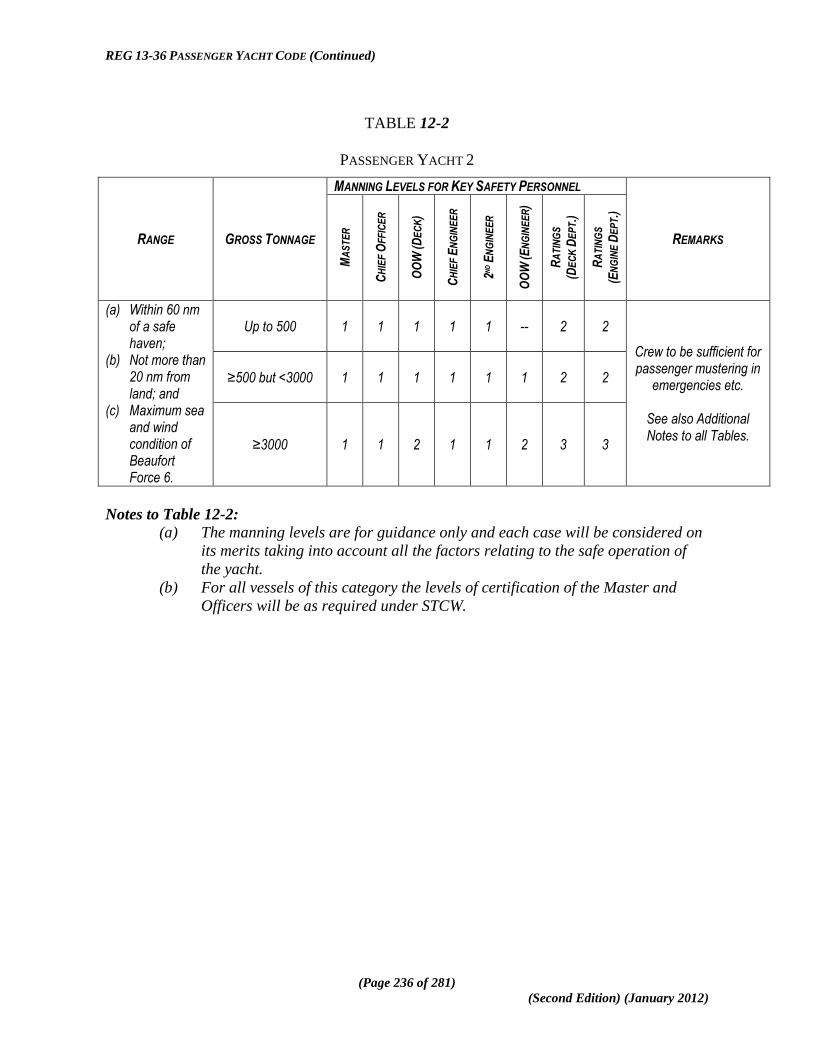
REG 13-36 PASSENGER YACHT CODE (Continued)
(Page 236 of 281)
(Second Edition) (January 2012)
TABLE 12-2
PASSENGER YACHT 2
RANGE GROSS TONNAGE
MANNING LEVELS FOR KEY SAFETY PERSONNEL
REMARKS
MA
ST
ER
CH
IEF
OF
FIC
ER
OO
W (D
EC
K)
CH
IEF
EN
GIN
EE
R
2ND E
NG
INE
ER
OO
W (E
NG
INE
ER
)
RA
TIN
GS
(DE
CK
DE
PT.)
RA
TIN
GS
(EN
GIN
E D
EP
T.)
(a) Within 60 nm of a safe haven;
(b) Not more than 20 nm from land; and
(c) Maximum sea and wind condition of Beaufort Force 6.
Up to 500
1 1 1 1 1 -- 2 2
Crew to be sufficient for passenger mustering in
emergencies etc.
See also Additional Notes to all Tables.
≥500 but <3000
1 1 1 1 1 1 2 2
≥3000 1 1 2 1 1 2 3 3
Notes to Table 12-2:
(a) The manning levels are for guidance only and each case will be considered on
its merits taking into account all the factors relating to the safe operation of
the yacht.
(b) For all vessels of this category the levels of certification of the Master and
Officers will be as required under STCW.

REG 13-36 PASSENGER YACHT CODE (Continued)
(Page 237 of 281)
(Second Edition) (January 2012)
TABLE 12-3
PASSENGER YACHT 1
RANGE GROSS TONNAGE
MANNING LEVELS FOR KEY SAFETY PERSONNEL
REMARKS
MA
ST
ER
CH
IEF
OF
FIC
ER
OO
W (D
EC
K)
CH
IEF
EN
GIN
EE
R
2ND E
NG
INE
ER
OO
W (E
NG
INE
ER
)
RA
TIN
GS
(DE
CK
DE
PT.)
RA
TIN
GS
(EN
GIN
E D
EP
T.)
Prescribed International
Voyage86
Up to 500 1 1 1 1 1 -- 2 2 Crew to be sufficient for passenger mustering in
emergencies etc.
See also Additional Notes to all Tables.
≥500 but <3000 1 1 1 1 1 1 2 2
≥3000
1 1 2 1 1 2 3 3
Notes to Table 12-3:
(a) The manning levels are for guidance only and each case will be considered on
its merits.
(b) For all vessels of this category the levels of certification of the Master and
Officers will be as required under STCW regardless of the length of the
prescribed voyage.
86
A ―Prescribed International Voyage‖ is an international voyage during the course of which a ship is not more
than 200 nautical miles from a port or place in which the passengers and crew could be placed in safety and
within a geographical area which limits the length of the voyage to a maximum of 1000 nautical miles from the
initial point of departure, as specified in any Certificate issued in accordance with the Code with respect to the
ship.

REG 13-36 PASSENGER YACHT CODE (Continued)
(Page 238 of 281)
(Second Edition) (January 2012)
TABLE 12-4
COMMERCIAL PLEASURE YACHT - UNLIMITED
RANGE GROSS TONNAGE
MANNING LEVELS FOR KEY SAFETY PERSONNEL
REMARKS
MA
ST
ER
CH
IEF
OF
FIC
ER
OO
W (D
EC
K)
CH
IEF
EN
GIN
EE
R
2ND E
NG
INE
ER
OO
W (E
NG
INE
ER
)
RA
TIN
GS
(DE
CK
DE
PT.)
RA
TIN
GS
(EN
GIN
E D
EP
T.)
Unlimited Any Tonnage 1 1 2 1 1 2 3 3
Any pleasure yacht engaged in trade and operating over an unlimited geographical range is in effect a SOLAS Convention passenger ship and subject to all the applicable requirements of the STCW Convention.
Additional Notes applicable to all Tables:
1. It is emphasised that the Manning Tables 12-1 to 12-4 given in this subsection are
for guidance only and the Tables do not necessarily represent any minimum
manning scale. There are many factors and variables to be taken into account in
determining the appropriate minimum safe manning level for a Passenger Yacht
and it is the responsibility of owners, masters and operators of the vessel to ensure
that all relevant factors are taken into consideration when submitting proposal for
a Safe Manning Document. In this regard due account also needs to be taken of
the fact that minimum safe manning levels do not necessarily provide a sufficient
number of crew for the day to day non-safety operations of the vessel.
2. In all cases full account shall be taken of relevant IMO Guidelines on Safe
Manning including, but not limited to IMO Resolution A.890(21) (as amended
from time to time), on the principles of safe manning.
3. Gross tonnage, geographical or weather limitations are not of themselves
necessarily the main or appropriate criteria in determining safe manning levels,
since a vessel operating to a heavy schedule of port calls, regardless of its size,
may well need increased levels of manning to maintain appropriate safety
standards and marine environment protection, including hours of rest, given the
increased workload of the crew under such circumstances.
12.6 Medical Fitness:
All seafarers serving on board vessels to which the Code applies shall be in possession of a
valid Medical Fitness Certificate issued or recognised by the Administration.

REG 13-36 PASSENGER YACHT CODE (Continued)
(Page 239 of 281)
(Second Edition) (January 2012)
12.7 Hours of Work and Rest:
(1) All members of the yacht‟s complement, including the master, shall have minimum rest
periods and maximum periods on duty (emergencies excepted) in accordance with the
provisions of the STCW Convention, ILO Conventions and national legislation.
(2) Owners and operators of passenger yachts shall ensure that the master, officers and
ratings do not work more hours than is safe in relation to the performance of their
duties and the safety of the ship in accordance with the provisions referred to in
subsection 12.5(1) and the master shall ensure that these provisions are adhered to on
board by suitable arrangements with respect to the assignment of duties; manning
levels should therefore be such as to ensure that the master, officers and crew are
afforded the opportunity to take the minimum rest periods.
(3) The time and place of rest periods should be such as to ensure that such periods can
be taken in a suitable environment conducive to achieving an effective rest.
(4) Further guidance about fitness for duty is contained in section B-VIII/1 of the STCW
Code.
(5) A record of the actual hours of work performed by the individual seafarer shall be
maintained on board, in order to verify that the minimum periods of rest required
under applicable international instruments and national legislation have been
complied with.

REG 13-36 PASSENGER YACHT CODE (Continued)
(Page 240 of 281)
(Second Edition) (January 2012)
This page is intentionally added to achieve correct pagination.

REG 13-36 PASSENGER YACHT CODE (Continued)
(Page 241 of 281)
(Second Edition) (January 2012)
CHAPTER 13
MEDICAL CARE
AND CARRIAGE OF MEDICAL STORES
13.1 Medical Care for Seafarers:
(1) The requirements for on board health and medical care set out in this Chapter include
standards for measures aimed at providing seafarers with health protection and
medical care as comparable as possible to that which is generally available to
workers ashore.
(2) The health protection and medical care shall in principle be provided at no cost to the
seafarers.
(3) The employer and master shall ensure that all seafarers are covered by adequate
measures providing for health protection and medical care, including essential dental
and optical care which-
(a) ensure the application to seafarers of any general provisions on occupational
health protection and medical care relevant to their duties, as well as special
provisions specific to work on board ship;
(b) give seafarers the right to visit a qualified medical doctor or dentist without
delay in ports of call, where practicable;
(c) ensure that seafarers are given health protection and medical care as
comparable as possible to that which is generally available to workers ashore,
including prompt access to the necessary medicines, medical equipment and
facilities for diagnosis and treatment and to medical information and
expertise;
(d) give seafarers the right to visit a qualified medical doctor or dentist without
delay in ports of call, where practicable;
(e) are not limited to treatment of sick or injured seafarers but include measures
of a preventative character such as health promotion and health education
programmes; and
(f) minimise the risk of infection and ensure appropriate preventative measures
such as immunisation are taken.
13.2 Provision of On-board Medical Care:
The carriage of medical stores and equipment as provided for in this Chapter is designed to
provide an appropriate level of primary care for all persons on board pending, where
necessary, the provision of shore based medical services.

REG 13-36 PASSENGER YACHT CODE (Continued)
(Page 242 of 281)
(Second Edition) (January 2012)
13.3 Medical Cabinet:
(1) A cabinet or other suitable facility for storing medicines and other medical stores
shall be provided and the cabinet, shall be well ventilated and fitted in a place in the
crew area of the ship which is-
(a) always dry;
(b) readily accessible from (but not sited in) the permanent or temporary hospital;
and
(c) not subject to abnormal heat.
(2) The medical cabinet shall be provided with the following-
(a) an outer door with an efficient lock;
(b) where controlled drugs are to be stored, an inner cupboard fitted with a door
and a lock which cannot be opened by the same key as the lock to the outer
door;
(c) suitable arrangements for the storage of the medicines, medical stores and
associated measuring devices; and
(d) a dispensing counter with a surface that can be easily kept clean.
(3) The medical cabinet shall be lit by an electric light (which may be inside or
immediately outside it) which enables the contents to be clearly seen.
13.4 Carriage of Medical Stores:
The ship shall carry on board medical stores and equipment as specified in the Table below-
Table of Medical Stores and Equipment to be Carried
Category of Passenger Yacht Scale of Medical Stores and Equipment
to be Carried
Passenger Yacht 2 Medical stores and equipment as specified for a Category B ship in Annex 1 of MSN 1768
87.
Yachts (other than Passenger Yachts II)
Medical stores and equipment as specified for a Category A ship in Annexes 1 and 2 of MSN 1768
56.
All Passenger Yachts
A Medical First Aid Kit for every 100 persons or fraction thereof carried on the ship in accordance with Annex 3 of MSN 1768
80 and in any case at least one
Medical First Aid Kit shall be carried.
87
UK Merchant Shipping Notice MSN 1768 – Ship‘s Medical Stores, as may be amended from time to time.

REG 13-36 PASSENGER YACHT CODE (Continued)
(Page 243 of 281)
(Second Edition) (January 2012)
13.5 Standards of Medical Stores:
All medical stores required to be kept on board ship shall conform to the standards and
requirements of the British National Formulary, the British Pharmacopoeia, the European
Pharmacopoeia, or the United States Pharmacopoeia, and with the requirements and
specifications of MSN 176856
.
13.6 Carriage of Medical Guides:
The ship shall carry guides as to the use of medical stores specified in section 13.3 including
in particular instructions for the use of antidotes, as specified in MSN 1768.
13.7 Medical Advice:
All ships should carry a complete and up-to-date list of radio stations through which medical
advice can be obtained; and if equipped with a system of satellite communication, carry an
up-to-date and complete list of coast earth stations through which medical advice can be
obtained. Seafarers with responsibility for medical care or medical first aid on board should
be instructed in the use of the ship‟s medical guide and the medical section of the most recent
edition of the International Code of Signals so as to enable them to understand the type of
information needed by the advising doctor as well as the advice received.
13.8 Inspection of Medicines and Medical Stores:
The medicine chest and its contents, as well as the medical equipment and medical guide
carried on board, should be properly maintained and inspected at regular intervals, not
exceeding 12 months, by a competent person or authority, who should ensure that the
labelling, expiry dates and conditions of storage of all medicines and directions for their use
are checked and all equipment functioning as required.
13.9 Carriage of Doctors or Medically Trained Personnel:
(1) Ships carrying 100 or more persons and undertaking international voyages in excess
of 600 miles shall carry a qualified medical doctor who is responsible for providing
medical care.
(2) In passenger yachts not required to carry a doctor the master shall ensure that any
medical attention or treatment administered on board to any person is given either by
the master or under his supervision by a person so appointed by him for the purpose

REG 13-36 PASSENGER YACHT CODE (Continued)
(Page 244 of 281)
(Second Edition) (January 2012)
provided that the person so appointed shall have received medical training to an
appropriate level in accordance with the STCW Convention.

REG 13-36 PASSENGER YACHT CODE (Continued)
(Page 245 of 281)
(Second Edition) (January 2012)
ANNEX 1
Classification Societies and other Bodies appointed as Recognized
Organizations by the National Maritime Administration concerned.
(To be completed as appropriate by each national Administration)

REG 13-36 PASSENGER YACHT CODE (Continued)
(Page 246 of 281)
(Second Edition) (January 2012)
This page is intentionally added to achieve correct pagination

REG 13-36 PASSENGER YACHT CODE (Continued)
(Page 247 of 281)
(Second Edition) (January 2012)
ANNEX 2
TECHNICAL STANDARDS FOR HELICOPTER LANDING AREAS AND
HELICOPTER OPERATING STANDARDS.
PREAMBLE TO ANNEX 2
(This Preamble is provided for explanatory purposes and is not part of the Annex 2 or Code provisions)
1. This updated Annex has been takes into account the nature of helicopter operations on
large yachts. In general terms the development of the requirements for helicopter operations
in the marine sector and in particular helidecks has largely been driven by the offshore oil
and gas industry. Whilst some of the core provisions and philosophies are of course relevant
in any scenario involving helicopter operations on ships, the large yacht sector does operate
in quite a different environment to the offshore industry and therefore the yacht sector is
better served and appropriate safety standards maintained if this is recognised with respect to
the requirements for helicopter operations in this area.
2. Annex 6 of the LY2 Code has been used as the basis for Annex 2 of this Code but it has
been modified as outlined above. Specifically, the following revisions are among those which
have been made-
(a) the requirement for a landing area safety net has been omitted since this is
very much a requirement which is more relevant to the offshore petroleum
industry operations.
(b) the “falling gradient” provision has been removed on the basis that this is not
relevant to large yacht operations; the falling gradient requirement is based
on the assumption that a helicopter will approach the landing area in an
athwartships direction whilst in reality however, helicopters will fly up the
wake of the yacht while it is under way and will land facing fore and aft on the
helideck and therefore the falling gradient is irrelevant; this angle of approach
is also safer as the vessel is generally steaming into wind and sea which means
there is less helideck movement and also the pilot has a far better overshoot
capability with an engine failure from this approach angle;
(c) in parallel with these modifications greater emphasis has been put on risk
assessment at the design stage as well as early liaison with the appropriate
civil aviation authorities to ensure that all relevant aspects of the proposed
operation are properly covered.
November 2010

REG 13-36 PASSENGER YACHT CODE (Continued)
(Page 248 of 281)
(Second Edition) (January 2012)
LAYOUT
SECTION ETC. NO. SUBJECT
PAGE NO. Section Subsection From To
1 Applicability 229 ---
2 General Considerations 229 ---
3 Helicopter Landing Areas – Physical Characteristics 230 239
3-1 General 230 231
3-2 Helicopter Landing Area Design Considerations
– Environmental Effects 231 237
3.3 Helicopter Tie-Down Points 237 238
3.4 Safety Net 238 ---
3.5 Access Points 238 239
4 Visual Aids 239 246
5 Helicopter Landing Area (HLA)Operational Standards 246 250
5.1 Movement of HLA due to Wave Motions at Ship 246 249
5.2 Aircraft Operational Data – Reporting and
Recording 248 ---
5.3 HLA Operations Manual and General
Requirements 248 ---
5.4 Helicopter Operations Support Equipment 249 ---
5.5 Radio Communications Equipment 249 ---
5.6 Risk Assessment 249 250
5.7 Crew Training 250 ---
6 Example Instruction Checklist 250 253
6.1 General 250 ---
6.2 Helicopter Landing Area Dimensions 251 ---
6.3 Helicopter Landing Area Conditions 251 ---
6.4 Environment 251 ---
6.5 Obstacle Protected Surfaces (Minima) 251 ---
6.6 Visual Aids 252 ---
6.7 Fuel Systems 252 ---
6.8 Rescue and Fire Fighting Facilities 252 ---
6.9 Crew Training Certification 253 ---
7 Helicopter Hangar Facilities 253 254
8 Helicopter Fuelling Facilities 254 263
8.1 General 254 ---
8.2 Storage of Aviation Fuel 255 256
8.3 Fuel Pumping and Storage Tank Filling 256 257
8.4 Refuelling and Defuelling Helicopters 258 ---
8.5 Prevention of Fuel Contamination 258 259
8.6 Fuel Pumping Spaces and Compartments 259 ---
8.7 Ventilation 260 ---
8.8 Non-sparking Fans for Hazardous Areas 260 263

REG 13-36 PASSENGER YACHT CODE (Continued)
(Page 249 of 281)
(Second Edition) (January 2012)
1 APPLICABILITY:
1.1 This Annex outlines the minimum standards for helicopter landing areas, and
associated facilities on board vessels within the scope of this Code where helicopter
operations to or from the vessel are required. It also addresses operational
considerations as related to the yacht crew.
1.2 This Annex does not address helicopter flight operations in any detail. It is intended
as a technical standard for the landing area and associated on-board helicopter
facilities. The helicopter pilot/operator is responsible for ensuring that the
requirements of the Administration with which the helicopter is registered and the
requirements of the Administration responsible for the airspace in which the helicopter
is operating are complied with in full. The Aviation Inspection Body may provide
further guidance.
1.3 Enquiries regarding operational (flight) limitations based on non-compliances of the
landing area should be directed to the Aviation Inspection Body.
2 GENERAL CONSIDERATIONS:
2.1 Requirements with respect to a Helicopter Landing Area (HLA) on a vessel results
from the need to ensure that helicopters are afforded sufficient space to be able to
operate safely at all times in the varying conditions experienced.
2.2 In order to ensure safe operation it is envisaged that limitations regarding the
availability of the landing area will be applied by the Aviation Inspection Body on
behalf of the Administration.
2.3 The helicopter‘s performance requirements and handling techniques are contained in,
and governed by, the Rotorcraft Flight Manual and/or the operator‘s Operations
Manual.
2.4 In all cases, a formal and documented risk assessment of the operation should be
carried out by a suitably experienced and qualified individual authorised by the ship‘s
Flag Administration. The risk assessment should establish the hazards and resultant
risks associated with the operation of each helicopter type that it is planned to utilise
the HLA of the yacht concerned. This should include the physical requirements for
the characteristics of the landing area.

REG 13-36 PASSENGER YACHT CODE (Continued)
(Page 250 of 281)
(Second Edition) (January 2012)
3 HELICOPTER LANDING AREAS – PHYSICAL CHARACTERISTICS:
3.1 General:
3.1.1 This section provides information on physical requirements for the
characteristics of helicopter landing areas on a yacht within the scope of the
Code.
3.1.2 The risk assessment carried out as above in order to establish the adequacy of
the landing area should include, for each helicopter landing area, the proposed
maximum size of helicopter in terms of D-value and the proposed maximum
take-off weight of the heaviest helicopter in terms of ―t‖ value for which it is
proposed each landing area is certificated with regard to size and strength.
3.1.3 The criteria which follow (see Table 1) are based on helicopter size and weight
and are for guidance only.
3.1.4 In addition to the risk assessment, the following plans and particulars should be
submitted to the Aviation Inspection Body, Certifying Authority and
Administration (as appropriate) for approval-
(a) Hangar general arrangement (showing dimensions and structural
considerations).
(b) Helicopter lift and movement arrangements (if appropriate).
(c) Structural fire protection.
(d) Fire detection and extinguishing arrangements
Table 1
D-Value and Helicopter Type Criteria (Not Exhaustive)
TYPE D VALUE
(M)
PERIMETER
„D‟
MARKING
ROTOR
DIAMETER
(M)
MAX.
WEIGHT
(KG)
„T‟
VALUE
Eurocopter
EC120 11.52 12 10.00 1715 1.7
Bell 206 B3 11.96 12 10.16 1451/1519 1.5
Bell 206 L4 12.91 13 11.28 2018 2.0
Bell 407 12.61 13 10.66 2268 2.3
Eurocopter
EC130 12.64 13 10.69 2400 2.4
Eurocopter
AS350 B3 12.94 13 10.69 2250 2.3
Eurocopter 12.94 13 10.69 2600 2.6

REG 13-36 PASSENGER YACHT CODE (Continued)
(Page 251 of 281)
(Second Edition) (January 2012)
TYPE D VALUE
(M)
PERIMETER
„D‟
MARKING
ROTOR
DIAMETER
(M)
MAX.
WEIGHT
(KG)
„T‟
VALUE
AS355
Eurocopter
EC135 12.10 12 10.20 2720 2.7
Agusta A119 13.02 13 10.83 2720 2.7
Bell 427 13.00 13 11.28 2971 3.0
Eurocopter
EC145 13.03 13 11.00 3585 3.6
Agusta A109 13.04 13 11.00 2850 2.9
Agusta
Grand 12.96 13 10.83 3175 3.2
Eurocopter
AS365 N3 13.73 14 11.94 4300 4.3
Eurocopter
EC155 B1 14.30 14 12.60 4920 4.9
Bell 430 15.29 15 12.80 4218 4.2
Sikorsky S76 16.00 16 13.40 5318 5.3
Agusta
Westland
139
16.66 17 13.80 6400 6.4
Bell 412 17.10 17 14.02 5398 5.4
3.2 Helicopter Landing Area Design Considerations – Environmental Effects:
Introduction
3.2.1 The safety of helicopter flight operations can be seriously degraded by
environmental effects that may be present around vessels. The term
―environmental effects‖ describes the effects of the vessel, its systems, and
forces in the surrounding environment, which result in a degraded local
environment in which the helicopter is expected to operate. These
environmental effects are typified by structure-induced turbulence, and
turbulence/thermal effects caused by exhaust emissions. Controls in the form
of landing area availability restrictions may be necessary and should be
imposed via the Aviation Inspection Body. Such restrictions can be minimised
by careful attention to the design and layout of the vessel topsides and, in
particular, the location of the helicopter landing area.

REG 13-36 PASSENGER YACHT CODE (Continued)
(Page 252 of 281)
(Second Edition) (January 2012)
Guidance for Landing Area Design Considerations
3.2.2 Guidance for landing area design considerations are given in UK Civil Aviation
Authority Paper 2004/02 (as may be amended from time to time) which should
be consulted by designers of helicopter landing areas at the earliest possible
stage of the design process and is available through the CAA website
(www.caa.co.uk).
3.2.3 All new helicopter landing areas, or modifications to existing topside
arrangements which could potentially have an effect on the environmental
conditions due to turbulence around an existing helicopter landing area, or
helicopter landing areas where operational experience has highlighted potential
airflow problems should be subject to appropriate wind tunnel testing or
Computational Fluid Dynamics (CFD) studies to establish the wind
environment in which helicopters will be expected to operate. Operations to a
vessel underway where the helideck will be subjected to relative rather than
true wind velocity should be taken into consideration. As a guide the standard
deviation of the vertical airflow velocity should be limited to 1.75m/s. This
airflow velocity should be applied to the recommended approach/departure
path and landing/take off phase of the aircraft. The helicopter pilot/operator
and Aviation Inspection Body should be informed at the earliest opportunity of
any wind conditions for which this criterion is not met in order to allow the
appropriate platform availability restrictions/limitations to be defined if
necessary.
3.2.4 Designers of helicopter landing areas should commission a survey of ambient
temperature rise based on a Gaussian dispersion model and supported by wind
tunnel tests or CFD studies for new build helicopter landing areas,
modifications to existing topside arrangements, or for helicopter landing areas
where operational experience has highlighted potential thermal problems.
When the results of such modelling and/or testing indicate that there may be a
rise of air temperature of more than 2°Centigrade (C) (averaged over a 3
second time interval), the helicopter pilot/operator and Aviation Inspection
Body should be consulted at the earliest opportunity so that appropriate
platform availability restrictions/limitations may be applied if necessary.
Size of Landing Area and Obstacle Protected Surfaces
3.2.5 For any particular type of single main rotor helicopter, the helicopter landing
area should, wherever possible, be sufficiently large to contain a circle of
diameter D equal to the largest dimension of the helicopter when the rotors are

REG 13-36 PASSENGER YACHT CODE (Continued)
(Page 253 of 281)
(Second Edition) (January 2012)
turning. This D circle should be totally unobstructed (see Table 1 for D
values). Due to the actual shape of most helicopter landing areas the D circle
will be ‗imaginary‘ but the helicopter landing area shape should be capable of
accommodating such a circle within its physical boundaries. It is possible to
reduce the width to a value equivalent of 0.83D but the longitudinal length
must be at least equivalent to 1.0D.
3.2.6 For operations with limited touchdown directions, the LHA should contain an
area within which can be accommodated two opposing arcs of a circle with a
diameter of not less than 1D in the helicopter‘s longitudinal direction. The
minimum width of the landing area shall be not less than 0.83D. In such
arrangements of landing areas, the yacht will need to be manoeuvred to ensure
that the relative wind is appropriate to the direction of the helicopter
touchdown heading. The touchdown heading of the helicopter is limited to the
angular distance subtended by the 1D arcs headings, minus 15° at each end of
the arc. See Figure 1 below.
Figure 1
3.2.7 From any point on the periphery of the above mentioned D circle an obstacle-
free approach and take-off sector should be provided which totally
encompasses the safe landing area (and D circle) and which extends over a
sector of at least 210°. Within this sector, from the periphery of the landing
area and out to a distance that will allow for an unobstructed departure path
appropriate to the helicopter that the landing area is intended to serve, only the

REG 13-36 PASSENGER YACHT CODE (Continued)
(Page 254 of 281)
(Second Edition) (January 2012)
following items may exceed the height of the landing area, but should not do
so by more than 250 millimetres-
(a) the guttering (associated with the requirements in section 3.2.13;
(b) the lighting required by sections 4.12 to 4.21;
(c) the foam monitors;
(d) those handrails and other items associated with the landing area
which are incapable of complete retraction or lowering for helicopter
operations; and
(e) tie down points.
3.2.8 The bisector of the 210° Obstacle Free Sector (OFS) should normally pass
through the centre of the D circle. The sector may be ‗swung‘ by up to 15° as
shown in Figure 1 below. Acceptance of the ‗swung‘ criteria will normally
only be applicable to existing vessels.
3.2.9 The diagram at Figure 2 shows the extent of the two segments of the 150°
Limited Obstacle Sector (LOS) and how these are measured from the centre of
the (imaginary) ‗D‘ Circle and from the perimeter of the Safe Landing Area
(SLA). This diagram assumes, since helicopter landing areas are designed to
the minimum requirement of accommodating a 1 ‗D‘ Circle, that the ‗D‘ Circle
perimeter and SLA perimeter are coincidental. No objects above 0.05D are
permitted in the first (hatched area in Figure 2) segment of the LOS. The first
segment extends out to 0.62D from the centre of the ‗D‘ Circle, or 0.12D from
the SLA perimeter marking.
The second segment of the LOS, in which no obstacles are permitted within a
rising 1:2 slope from the upper surface of the first segment, extends out to
0.83D from the centre of the ‗D‘ Circle, or a further 0.21D from the edge of the
first segment of the LOS.
The exact point of origin of the LOS is assumed to be at the periphery of the
‗D‘ Circle.

REG 13-36 PASSENGER YACHT CODE (Continued)
(Page 255 of 281)
(Second Edition) (January 2012)
Figure 2 - Obstacle Limitation showing position of Aiming Circle
Drawing not to scale
3.2.10 Some helicopter landing areas are able to accommodate a SLA which covers a
larger area than the declared ‗D‘ value; a simple example being a rectangular
deck with the minor dimension able to contain the ‗D‘ Circle. In such cases it
is important to ensure that the origin of the LOS (and OFS) is at the SLA
perimeter as marked by the perimeter line. Any SLA perimeter should
guarantee the obstacle protection afforded by both segments of the LOS. The
respective measurements of 0.12D from the SLA perimeter line, plus a further
0.21D are to be applied. On these larger decks there is thus some flexibility in
deciding the position of the perimeter line and SLA in order to meet the LOS
requirements and when considering the position and height of fixed obstacles.

REG 13-36 PASSENGER YACHT CODE (Continued)
(Page 256 of 281)
(Second Edition) (January 2012)
Separating the origin of the LOS from the perimeter of the ‗D‘ Circle in Figure
2 and moving it to the right of the page will demonstrate how this might apply
on a rectangular SLA.
3.2.11 The extent of the LOS segments will, in all cases, be lines parallel to the SLA
perimeter line and follow the boundaries of the SLA perimeter (see Figure 2
above). Only in cases where the SLA perimeter is circular will the extent be in
the form of arcs to the ‗D‘ circle. However, taking the example of an
octagonal SLA as drawn at Figure 1, it would be possible to replace the angled
corners of the two LOS segments with arcs of 0.12D and 0.33D centred on the
two adjacent corners of the SLA; thus cutting off the angled corners of the
LOS segments. If these arcs are applied they should not extend beyond the
two corners of each LOS segment so that minimum clearances of 0.12D and
0.33D from the corners of the SLA are maintained. Similar geometric
construction may be made to a square or rectangular SLA but care should be
taken to ensure that the LOS protected surfaces minima can be satisfied from
all points on the SLA perimeter.
Landing Area Surfaces
3.2.12 The landing area should have an overall coating of non-slip material and all
markings on the surface of the landing area should be made with the same non-
slip materials. Whilst extruded section or grid construction aluminium (or
other) decks may incorporate adequate non-slip profiles in their design, it is
preferable that they are also coated with a non-slip material unless adequate
friction properties have been designed into the construction. It is important that
the friction properties exist in all directions. Over-painting friction surfaces on
such designs may compromise the friction properties. Recognised surface
friction material is available commercially.
3.2.13 Helicopter landing areas should be cambered to a maximum gradient of 1:100.
Any distortion of the helicopter landing area surface due to, for example, loads
from a helicopter at rest should not modify the landing area drainage system to
the extent of allowing spilled fuel to remain on the deck. A system of
guttering should be provided around the perimeter to prevent spilled fuel from
falling on to other parts of the vessel and to conduct the spillage to an
appropriate drainage system.
The capacity of the drainage system should be sufficient to contain the
maximum likely spillage of fuel on the deck. The calculation of the amount of
spillage to be contained should be based on an analysis of helicopter type, fuel
capacity, typical fuel loads and uplifts. The design of the drainage system

REG 13-36 PASSENGER YACHT CODE (Continued)
(Page 257 of 281)
(Second Edition) (January 2012)
should preclude blockage by debris. The helicopter landing area should be
properly sealed so that spillage will only route into the drainage system.
3.3 Helicopter Tie-Down Points:
3.3.1 Sufficient flush-fitting (when not in use) or removable semi-recessed tie-down
points should be provided for securing the maximum sized helicopter for
which the helicopter landing area is designed. They should be so located and
be of such strength and construction to secure the helicopter when subjected to
expected weather conditions. They should also take into account the inertial
forces resulting from the movement of the vessel.
3.3.2 Tie-down rings should be compatible with the dimensions of tie-down strop
attachments. Tie-down rings and strops should be of such strength and
construction so as to secure the helicopter when subjected to expected weather
conditions. The maximum bar diameter of the tie-down ring should be
compatible with the strop hook dimension of the tie down strops carried by the
helicopter operator.
An example of a suitable tie-down configuration is shown at Figure 3. The
Aviation Inspection Body or helicopter operator will provide guidance on the
configuration of the tie-down points for specific helicopter types.
Figure 3 – Example of Suitable Tie-Down configuration

REG 13-36 PASSENGER YACHT CODE (Continued)
(Page 258 of 281)
(Second Edition) (January 2012)
Notes to Figure 3-
1. The tie-down configuration should be based on the centre of the Aiming
Circle marking.
2. Additional tie-downs will be required in a parking area.
3. The outer circle is not required for „D‟ values of less than 22.2 metres.
3.4 Safety Net:
3.4.1 Safety nets for personnel protection should be installed around the landing area
where there is a danger of personnel falling overboard. This should be looked
at on an individual basis and a suitable Risk Assessment /Safety Case
conducted. Where adequate structural protection against falls exists or
adequate helideck procedures are in place with an appropriate risk assessment
conducted by the Administration, then safety nets may be omitted. If fitted,
the netting used should be of a flexible nature, with the inboard edge fastened
level, just below the edge of the helicopter landing area. The net itself should
extend 1.5 metres in the horizontal plane and be arranged so that the outboard
edge is not above the level of the landing area so that it has an upward and
outward slope of at least 10°. It may be possible to incorporate dropped rails
in place of a safety net but the dimensions and guidance above pertaining to
safety net should be adhered to.
3.5 Access Points:
3.5.1 Many helicopters have passenger access on one side only and helicopter
landing orientation in relation to landing area access points becomes important
because it is necessary to ensure that embarking and disembarking passengers
are not required to pass around the helicopter tail rotor, or under the front of
the main rotor of those helicopters with a low profile rotor, should a ‗rotors-
running turn-round‘ be conducted.
3.5.2 There should be a minimum of two access/egress routes to the helicopter
landing area- these should be 180° apart. The arrangements should be
optimised to ensure that, in the event of an accident or incident on the
helicopter landing area, personnel will be able to escape upwind of the landing
area. Adequacy of the emergency escape arrangements from the helicopter
landing area should be included in any evacuation, escape and rescue analysis
for the vessel, and may require a third escape route to be provided.

REG 13-36 PASSENGER YACHT CODE (Continued)
(Page 259 of 281)
(Second Edition) (January 2012)
3.5.3 Where foam monitors are co-located with access points, care should be taken
to ensure that no monitor is so close to an access point as to cause injury to
escaping personnel by operation of the monitor in an emergency situation.
3.5.4 Where handrails associated with landing area access/escape points exceed the
height limitations given at section 3.2.7 they should be retractable, collapsible
or removable. When retracted, collapsed or removed the rails should not
impede access/egress. Handrails which are retractable, collapsible and
removable should be painted in a contrasting colour scheme. Procedures
should be in place to retract, collapse, or remove them prior to helicopter
arrival. Once the helicopter has landed, and the crew has indicated that
passenger movement may commence, the handrails may be raised and locked
in position. The handrails should be retracted, collapsed, or removed again
prior to the helicopter taking-off.
Where anti-collision lights are utilised, the helicopter crew will ensure they are
switched off before the movement of passengers and/or freight takes place.
4. VISUAL AIDS:
4.1 The following sections outline the requirements for helicopter landing area markings
which should be permanently painted on the deck. Plans of the marking arrangements
including dimensions should be submitted to the Aviation Inspection Body for
approval.
4.2 Helicopter landing area perimeter line marking and lighting serves to identify the
limits of the Safe Landing Area (SLA) for day and night operations.
4.3 A wind direction indicator should be provided during helicopter operations and
located so as to indicate the clear area wind conditions at the vessel location. For the
purposes of this regulation the wind indicator may either be a dedicated windsock or
appropriate flag. It is often inappropriate to locate the indicator as close to the
helicopter landing area as possible where it may compromise obstacle protected
surfaces, create its own dominant obstacle or be subjected to the effects of turbulence
from structures resulting in an unclear wind indication. The wind indicator should be
illuminated for night operations.

REG 13-36 PASSENGER YACHT CODE (Continued)
(Page 260 of 281)
(Second Edition) (January 2012)
Helicopter Landing Area Markings (See Figure 4 below)
4.4 For the smallest landing areas (typically <16metres) it may be necessary to reduce the
size of the helideck markings appropriately. In such circumstances, the Aviation
Inspection Body should be consulted as soon as possible.
4.5 The colour of the helicopter landing area should where possible be a contrasting
colour to the rest of the vessel‘s deck. The perimeter of the SLA should be clearly
marked with a painted line 0.3 metres wide in a contrasting colour to the helideck.
Figure 4 - Markings (Single Main Rotor Helicopters)
4.6 The light grey colour of aluminium may be acceptable in specific helicopter landing
area applications where these are agreed with the Aviation Inspection Body. This
should be discussed in the early design phase. In such cases the conspicuity of the
helicopter landing area markings may need to be enhanced by, for example, outlining
the deck marking lines and characters with a thin black line. Alternatively,
conspicuity may be enhanced by overlaying white markings on a painted black
background.
4.7 A maximum allowable mass marking should be marked on the helicopter landing area
in a position which is readable from the preferred final approach direction i.e. towards
the obstacle-free sector origin. The marking should consist of a two or three digit
number expressed to one decimal place rounded to the nearest 100 kg and followed by

REG 13-36 PASSENGER YACHT CODE (Continued)
(Page 261 of 281)
(Second Edition) (January 2012)
the letter ‗t‘ to indicate the allowable helicopter weight in tonnes (1000 kg). The height
of the figures should be 0.9 metres with a line width of approximately 0.12 metres and
be in a colour which contrasts with the helicopter landing area surface (preferably
white: avoid black or grey).
4.8 An aiming circle (touchdown/positioning marking) for each helicopter landing area
should be provided as follows: (see Figures 2, 4, 5 and 6).
Figure 5
Aiming Circle Marking
Note: On a helideck the centre of the Touch Down/Position Marking
(TD/PM) circle will normally be located at the centre of the landing
area, except that the marking may be offset away from the origin of
the OFS by no more than 0.1D where an aeronautical study indicates
such offsetting to be beneficial, provided that the offset marking does
not adversely affect the safety of flight operations or ground handling
issues.
4.9 On smaller helicopter landing areas with a D value up to and including 16.00m and for
bow-mounted helicopter landing areas the aiming circle should be concentric with the
helicopter landing area centre to ensure maximisation of space all around for safe
personnel movement and optimisation of the visual cueing environment. The marking
should be a circle with an inner diameter of 0.5 times the certificated D-value of the
helicopter landing area and a line width of not less than 0.5m for landing areas with a
D-Value up to and including 16.00m and not less than 1.0m for landing areas with a

REG 13-36 PASSENGER YACHT CODE (Continued)
(Page 262 of 281)
(Second Edition) (January 2012)
D-Value greater than 16.00m. The circle should be in a contrasting colour to the
helideck.
4.10 On those decks where the aiming circle is concentric with the centre of the D circle or
SLA, the need for some mitigation against concerns over tail rotor clearances should be
considered; either by achieving more obstacle clearance in the 150° LOS or by
adopting appropriate operational procedures (e.g. vessel to provide relative wind from
beam or stern).
4.11 A ―H‖ painted in a colour contrasting with the deck (preferably white) should be co-
located with the aiming circle with the cross bar of the ―H‖ lying along the bisector of
the obstacle-free sector (see Figure 6). The minimum H dimensions are shown in
brackets for landing areas with a D-Value up to and including 16.00 metres and
without brackets for landing areas with a D-Value greater than 16.00 metres.
4.12 Where the obstacle-free sector has been swung in accordance with Section 3.2.8 the
positioning of the aiming circle and ―H‖ should comply with the normal unswung
criteria. The ―H‖ should, however, be orientated so that the bar is parallel to the
bisector of the swung sector.
Figure 6 – Dimensions of „H”
Lighting
4.13 Night helicopter operations to a vessel underway are demanding and should be
considered carefully. Providing the helicopter aircrew with the correct lighting

REG 13-36 PASSENGER YACHT CODE (Continued)
(Page 263 of 281)
(Second Edition) (January 2012)
configuration is paramount to safety. Night operations conducted inshore, in fair weather
with good background lighting are considerably less challenging that those operations
conducted far from the coast in heavy seas. These factors should be taken into account
when determining the level of operational capability required. Deep water operations
will invariably require pilot interpreted approach aid lighting.
4.14 The SLA should be delineated by green perimeter lights visible omnidirectionally
from on or above the landing area. These lights should be above the level of the deck
but should not exceed the height limitations in Section 3.2.7. The lights should be
equally spaced at intervals of not more than three metres around the perimeter of the
SLA, coincident with the line delineating the perimeter (see section 4.6).
4.15 In the case of square or rectangular decks there should be a minimum of four lights
along each side including a light at each corner of the safe landing area. The ‗main
beam‘ of the green perimeter lights should be of at least 30 candelas intensity (the full
vertical beam spread specification is shown in Table 2). Flush fitting lights may be
used at the inboard (150° LOS origin) edge of the SLA.
4.16 Where the declared D-value of the helicopter landing area is less than the physical
helicopter landing area, the perimeter lights should delineate the limit of the safe
landing area (SLA) so that the helicopter may land safely by reference to the perimeter
lights on the limited obstacle sector (LOS -150°) ‗inboard‘ side of the helicopter
landing area without risk of main rotor collision with obstructions in this sector. By
applying the LOS clearances (given in Section 3 paragraph 3.4) from the perimeter
marking, adequate main rotor to obstruction separation should be achieved.
Touchdown for normal landing should be made by reference to the aiming circle. On
helicopter landing areas where insufficient clearance exists in the LOS, a suitable
temporary arrangement to modify the lighting delineation of the SLA, where this is
found to be marked too generously, should be agreed with the Aviation Inspection
Body by replacing existing green lights with red lights of 30 candelas intensity around
the ‗unsafe‘ portion of the SLA (the vertical beam spread characteristics for red lights
should also comply with Table 2). The perimeter line, however, should be repainted
in the correct position immediately and the area of deck between the old and new
perimeter lines should be painted in a colour that contrasts with the main helicopter
landing area. Use of flush fitting lights in the 150° sector perimeter will provide
adequate illumination while causing minimum obstruction to personnel and equipment
movement.

REG 13-36 PASSENGER YACHT CODE (Continued)
(Page 264 of 281)
(Second Edition) (January 2012)
Table 2
ISO-candela Diagram for Helicopter Landing Area Perimeter Lights
Elevation Intensity
0° - 90° 60 cd max.*
>20° - 90° 3 cd min.
>10° - 20 15 cd min.
0° - 10° 30 cd min.
-180° Azimuth +180°
4.17 The whole of the safe landing area (SLA) should be adequately illuminated if intended
for night use. In the past, owners and operators have sought to achieve compliance by
providing deck level floodlights around the perimeter of the SLA and/ or by mounting
floodlights at an elevated location ‗inboard‘ from the SLA, e.g. floodlights angled
down from the top of a bridge or hangar. Experience has shown that floodlighting
systems, even when properly aligned, can adversely affect the visual cueing
environment by reducing the conspicuity of helicopter landing area perimeter lights
during the approach, and by causing glare and loss of pilots‘ night vision during hover
and landing. Furthermore, floodlighting systems often fail to provide adequate
illumination of the centre of the landing area leading to the so-called ‗black-hole
effect‘. It is essential therefore that any floodlighting arrangements take full account of
these problems.
4.18 The floodlighting should be arranged so as not to dazzle the pilot and, if elevated and
located off the landing area clear of the LOS, the system should not present a hazard to
helicopters landing and taking off from the helicopter landing area. All floodlights
should be capable of being switched on and off at the pilot‘s request. Setting up of
lights should be undertaken with care to ensure that the issues of adequate illumination
and glare are properly addressed and regularly checked. Adequate shielding of
‗polluting‘ light sources can easily be achieved early on in the design stage, but can
also be implemented on existing installations using simple measures. Temporary
working lights which pollute the helicopter landing area lighting environment should
be switched off during helicopter operations.
4.19 It is important to confine the helicopter landing area lighting to the landing area, since
any light overspill may cause reflections from the sea. The floodlighting controls
should be accessible to, and controlled by, the officer(s) in charge of the landing area
operations team(s).
4.20 In seeking to develop an alternative system to conventional floodlighting, it has been
demonstrated that arrays of segmented point source lighting (ASPSL) in the form of

REG 13-36 PASSENGER YACHT CODE (Continued)
(Page 265 of 281)
(Second Edition) (January 2012)
encapsulated strips of light emitting diodes (LEDs) can be used to illuminate the
aiming circle and landing area identification marking (‗H‘). This arrangement has
been found to provide the visual cues required by the pilot earlier on in the approach
and more effectively than by using floodlighting, and without the disadvantages
associated with floodlighting such as glare. Large yacht owners are encouraged to
consider appropriate systems in lieu of conventional floodlighting.
4.21 The quoted intensity values for lights apply to the intensity of the light emitted from
the unit when fitted with all necessary filters and shades (see also paragraphs 4.24. and
4.25 below).
4.22 The emergency power supply of the vessel should include the helicopter landing area
lighting. Any failures or outages should be reported immediately to the helicopter
pilot/operator. The lighting should be fed from an Uninterrupted Power Supply (UPS)
system capable of providing the required load for at least 15 minutes. This can be a
standalone supply or be an additional loading requirement for the vessel‘s emergency
power supplies.
Obstacles - Marking and Lighting
4.23 Fixed obstacles identified as a hazard to helicopters by the helicopter pilot/ operator,
or by the Aviation Inspection Body, should be clearly defined in any operations
manual (ISM procedure or Yacht Aviation File).
4.24 Omnidirectional red lights of at least 10 candelas intensity should be fitted at suitable
locations to provide the helicopter pilot with visual information on the proximity and
height of objects which are higher than the landing area and which are close to it or to
the LOS boundary. Objects which are more than 15 metres higher than the landing
area should be fitted with intermediate red lights of the same intensity spaced at 10
metre intervals down to the level of the landing area (except where such lights would
be obscured by other objects).
4.25 An omnidirectional red light of intensity 25 to 200 candelas should be fitted to the
highest point of the vessel. Where this is not practicable, the light should be fitted as
near to the extremity as possible.
4.26 Red lights should be arranged so that the location of the objects which they delineate
are visible from all directions above the landing area.
4.27 The emergency power supply of the yacht should include all forms of obstruction
lighting. Any failures or outages should be reported immediately to the helicopter
pilot/ operator. The lighting should be fed from an Uninterrupted Power Supply

REG 13-36 PASSENGER YACHT CODE (Continued)
(Page 266 of 281)
(Second Edition) (January 2012)
(UPS) system capable of providing the required load for at least 15 minutes. This can
be a standalone supply or be an additional loading requirement for the yacht‘s
emergency power supplies.
5 HELICOPTER LANDING AREA (HLA)OPERATIONAL STANDARDS:
5.1 Movement of HLA due to Wave Motions at Ship:
5.1.1 Yachts experience dynamic motions due to wave action which represent a
potential hazard to helicopter operations. For the helicopter operations
acceleration in pitch roll and heave will provide the limiting factor. These
limits are a combination of both vessel and helicopter capability. Operational
limitations based on limited pitch, roll, heave, may therefore be applied to the
landing area by the Aviation Inspection Body. Helicopter landing area
downtime due to excessive deck motion can be minimised by careful
consideration of the location of the landing area on the vessel at the design
stage. Guidance on helicopter landing area location and how to assess the
impact of the resulting motion on operability is presented in UK CAA Paper
2004/02 ―Helideck Landing Area Design Considerations – Environmental
Effects‖, as may be amended from time to time and which is available on the
Publications section of the UK CAA website at www.caa.co.uk. Designers of
helicopter landing areas should consult this paper at the earliest possible stage
of the design process.
5.1.2 The helicopter landing area will be limited to receiving helicopters in the
conditions agreed by the Aviation Inspection Body.
5.1.3 It is necessary for details of pitch, roll, and heave motions to be recorded on the
vessel prior to, and during, all helicopter movements. Pitch and roll reports to
helicopters should include values, in degrees, about both axes of the true
vertical datum (i.e. relative to the true horizon) and be expressed in relation to
the vessel‘s head. Roll should be expressed in terms of ‗port‘ and ‗starboard‘;
pitch should be expressed in terms of ‗up‘ and ‗down‘; heave should be
reported in a single figure, being the total heave motion of the helicopter
landing area rounded up to the nearest metre. Heave is to be taken as the
vertical difference between the highest and lowest points of any single cycle of
the helicopter landing area movement. The parameters reported should be the
maximum peak levels recorded during the ten minute period prior to
commencement of helicopter operations.

REG 13-36 PASSENGER YACHT CODE (Continued)
(Page 267 of 281)
(Second Edition) (January 2012)
5.1.4 The helicopter pilot is concerned, in order to make vital safety decisions, with
the amount of ‗slope‘ on, and the rate of movement of, the helicopter landing
area surface. It is therefore important that the roll values are only related to the
true vertical and do not relate to any ‗false‘ datum (i.e. a ‗list‘) created, for
example, by anchor patterns or displacement. There are circumstances in which
a pilot can be aided by amplification of the heave measurement by reference to
the time period (seconds) in terms of ‗peak to peak‘.
Reporting Format
5.1.5 A standard radio message should be passed to the helicopter which contains
the information on helicopter landing area movement in an unambiguous
format. This will, in most cases, be sufficient to enable the helicopter crew to
make safety decisions. Should the helicopter crew require other motion
information or amplification of the standard message, the crew will request it
(for example, yaw and heading information).
Standard Report example:
Situation: The maximum vessel movement (over the preceding ten
minute period) about the roll axis is 1° to port and 3° to starboard
(i.e. this vessel may have a permanent list of 1° to starboard and is
rolling a further 2° either side of this ‗false‘ datum). The maximum
vessel movement (over the preceding ten minute period) about the
pitch axis is 2° up and 2° down. The maximum recorded heave
amplitude over a single cycle (over the preceding ten minute period)
is 1.5 metres.
Report: „Roll 1° left and 3° right; Pitch 2° up and 2° down; heave
two metres‟.
5.1.6 It is important to ensure that the deck motions reported to the helicopter pilot
relate to the motion at the helicopter landing area. Very often pitch, roll and
heave measurements are taken from a source far removed from the helicopter
landing area location. If this source should happen to be midships and the
helicopter landing area is located, for example, high up on the bow, the actual
heave (and, in future accelerations,) at the helicopter landing area are likely to
be far in excess of the source measurement. Software packages are available to
provide helicopter landing area location corrected movement data from a source
at a different location. Ideally, deck motion measuring equipment should be
located at (attached to the underside of) the helicopter landing area.
5.2 Aircraft Operational Data – Reporting and Recording:

REG 13-36 PASSENGER YACHT CODE (Continued)
(Page 268 of 281)
(Second Edition) (January 2012)
5.2.1 In addition to the data covered by section 5.1.5 above, it is essential that yachts
are provided with means of ascertaining and reporting at any time-
(a) the wind speed and direction using aviation approved equipment to
ICAO standard;
(b) the air temperature;
(c) the barometric pressure using aviation approved equipment to ICAO
standard;
(d) the visibility, cloud base and cover; and
(e) the sea state.
5.2.2 Air temperature and barometric pressure should be measured by conventional
instruments approved to ICAO standards. An indication of wind speed and
direction will be provided visually to the pilot by the provision of a windsock
coloured so as to give maximum contrast with the background. However, for
recording purposes, an anemometer positioned in an unrestricted airflow is
required. A second anemometer, located at a suitable height and position can
give useful information on wind velocity at hover height over the helicopter
landing area in the event of turbulent or deflected airflows over the deck.
Visibility, cloud conditions, and sea state will normally be assessed by visual
observations.
5.2.3 Measuring instruments used to provide the data listed in sections 5.2.1 and 5.2.2
above should be periodically calibrated in accordance with the manufacturer‘s
recommendations in order to provide continuing accuracy.
5.3 HLA Operations Manual and General Requirements:
The maximum helicopter weight and ‗D‘ value for which the helicopter landing area has been
designed and the maximum size and weight of helicopter for which the vessel is certificated
should be included in the Helicopter Landing Area Operations Manual and Landing Area
Certificate. The extent of the obstacle-free area should also be stated and reference made to
any helicopter landing area operating limitation imposed by helicopter operators or the
Aviation Inspection Body as a result of non-compliances. Details of non-compliances
themselves should also be listed.

REG 13-36 PASSENGER YACHT CODE (Continued)
(Page 269 of 281)
(Second Edition) (January 2012)
5.4 Helicopter Operations Support Equipment:
5.4.1 Provision should be made for equipment needed for use in connection with
helicopter operations including-
(a) chocks and tie-down strops;
(b) a suitable power source for starting helicopters if helicopter shut-
down is seen as an operational requirement; and
(c) equipment for clearing the helicopter landing area of snow and ice
and other contaminants.
5.4.2 Chocks should be compatible with helicopter undercarriage/ wheel
configurations. Helicopter operating experience has shown that the most
effective chock for use on helicopter landing areas is the ‗rubber triangular‘ or
‗single piece fore and aft‘ type chocks may be used as long as they are suited to
all helicopters likely to operate to the helicopter landing area.
5.4.3 For securing helicopters to the helicopter landing area only adjustable tie-down
strops should be used.
5.5 Radio Communications Equipment:
5.5.1 At least one aeronautical frequency radio licensed by the Administration
responsible for the airspace in which the helicopter is intended to operate when
approaching the vessel should be fitted on board the vessel.
5.5.2 Radio operators of offshore aeronautical radio stations are required to hold a
Certificate of Competence. Further information can be found in CAA
Publication CAP 452 'Aeronautical Radio Station Operator's Guide'.
5.6 Risk Assessment:
5.6.1 A full risk assessment should be carried out addressing all the operations
anticipated with helicopter operations on board a yacht. This should include-
(a) Landing and securing
(b) Preparing for take off and taking off
(c) Unloading passengers, baggage and stores
(d) Refuelling

REG 13-36 PASSENGER YACHT CODE (Continued)
(Page 270 of 281)
(Second Edition) (January 2012)
(e) Securing
(f) Safe movement of personnel
5.6.2 The risk assessment should be submitted to the Administration. The risk
assessment to address the safe movement of personnel on the helicopter landing
area should also be submitted for approval by the Aviation Inspection Body to
demonstrate that safe passenger movement may take place without endangering
the safety of the helicopter or the life of personnel on-board.
5.7 Crew Training:
5.7.1 The yacht crew, as appropriate, should be trained to deal with normal helicopter
movements as well as abnormal and emergency situations. The training should
include dealing with fires and other possible emergency scenarios.
5.7.2 Specific training should be provided to the Helicopter Landing Officer (HLO)
by an appropriate training provider. Where there are refuelling facilities on
board, at least one member of crew should be trained in the handling of aviation
(Jet A1) fuel and associated quality control procedures.
5.7.3 Training of crewmembers and the HLO should include both practical and
theoretical sessions and, wherever possible, practical training should be carried
out on board.
5.7.4 The crew should practice dealing with the possible emergency scenarios
through regular drills on board with an annual inspection by an external auditor.
5.7.5 The emergency scenarios should be addressed in the yacht‘s contingency plans
and similar documents.
6 EXAMPLE INSTRUCTION CHECKLIST:
6.1 General:
The following checklist indicates in general terms the minimum number of helicopter landing
area physical characteristics which the Administration considers should be examined during
initial inspection and periodic surveys carried out by the Aviation Inspection Body to confirm
that there has been no alteration or deterioration in condition.
REG 13-36 PASSENGER YACHT CODE (Continued)
(Page 271 of 281)
(Second Edition) (January 2012)
6.2 Helicopter Landing Area Dimensions:
This shall include-
(a) D-value as measured;
(b) Declared D-value;
(c) deck shape; and
(d) scale drawings of deck arrangement.
6.3 Helicopter Landing Area Conditions:
This shall include-
(a) type of surface, condition, friction, contaminant free;
(b) fuel retention;
(c) deck landing area net;
(d) perimeter safety netting; and
(e) tie-down points.
6.4 Environment:
This shall include-
(a) machinery exhausts;
(b) hot and cold gas emissions; and
(c) presence of turbulence.
6.5 Obstacle Protected Surfaces (Minima):
This shall include-
(a) Obstacle Free Sector (210°);
(b) Limited Obstacle Sector (150°); and
(c) Note if (a) above is swung from normal axis.

REG 13-36 PASSENGER YACHT CODE (Continued)
(Page 272 of 281)
(Second Edition) (January 2012)
6.6 Visual Aids:
This shall include-
(a) deck surface;
(b) general condition of painted markings;
(c) location of H;
(d) Aiming Circle;
(e) maximum allowable weight marking;
(f) conspicuity of painted markings;
(g) wind indicator;
(h) perimeter lighting;
(i) floodlighting;
(j) obstruction lighting;
(k) marking of dominant obstacles; and
(l) shielding of working lights (helicopter landing area light pollution).
6.7 Fuel Systems:
This shall include-
(a) principal agent;
(b) complementary media;
(c) rescue equipment; and
(d) personal protective equipment.
6.8 Rescue and Fire Fighting Facilities:
This shall include-
(a) principal agent
(b) complementary media
(c) rescue equipment
(d) personal protective equipment

REG 13-36 PASSENGER YACHT CODE (Continued)
(Page 273 of 281)
(Second Edition) (January 2012)
6.9 Crew Training Certification:
This shall include qualifications and Training Records for the crew concerned.
7 HELICOPTER HANGAR FACILITIES:
General
7.1 Helicopter hangar arrangements on board should be in accordance with requirements
for helicopter refuelling and hangar facilities contained within SOLAS II-2. Helicopter
fuelling facilities on board should be in accordance with requirements for helicopter
refuelling and hangar facilities in SOLAS II-2. In addition, the applicable requirements
outlined in this Annex to the Code should be complied with in full unless a safety case
is made to, and approved by, the Administration, based on an alternative arrangement
according to Classification Society Rules or guidance from the Aviation or Petro-
Chemical industries. The requirements in this section are based upon the use of
helicopters run on Jet A1 fuel. When developing hangar arrangements, consideration
should be given to the type of fuel on which the helicopter to be stowed is run.
7.2 The following plans and particulars are to be submitted to the Classification Society
and Administration for approval-
(a) hangar general arrangement and structure;
(b) helicopter lift, hoist, and movement arrangements (if appropriate);
(c) structural fire protection;
(d) fire detection and extinguishing arrangements; and
(e) ventilation arrangements.
Hangar Design Considerations
7.3 Helicopter hangar(s) on board should be positioned, as far as is practicable, so as to
preclude excessive movement and acceleration forces. Guidance on this should be
sought from the helicopter manufacturer / operator. Where possible, the positioning of
hangar(s) should be determined through the use of computer modelling and/or wind
tunnel testing (refer also to Section 3.2.3).
7.4 The perimeter of hangar(s) and any associated entrance or hatchway inclusive of
helicopter lift arrangements should provide a stowage / maintenance box allowing for a

REG 13-36 PASSENGER YACHT CODE (Continued)
(Page 274 of 281)
(Second Edition) (January 2012)
minimum 0.5m clearance at any point around the helicopter and rotors when the
helicopter is in its stowed condition.
7.5 Where appropriate CCTV should be used to ensure visibility of the aircraft at all times.
8 HELICOPTER FUELLING FACILITIES:
8.1 General:
8.1.1 This section outlines the requirements for the storage and transfer of Jet A1
fuel. When developing fuelling arrangements, consideration should be given to
the type of fuel on which the helicopter to be operated is run. In addition, all
facilities for the storage and handling of aviation fuels on board should be grade
identified using the appropriate American Petroleum Industry (API) markings
for the grade of fuel used. Aviation fuel facilities should also be fully
segregated from any other fuel system.
8.1.2 Refuelling and defueling operational considerations should be agreed with the
helicopter pilot / operator and Aviation Inspection Body.
8.1.3 The following plans and particulars are to be submitted to the Aviation
Inspection Body and Classification Society for approval-
(a) description of fuel with statement of minimum flash point (closed cup
test);
(b) arrangements of fuel storage and piping;
(c) arrangements for drainage, ventilation and sounding of spaces
adjacent to storage tanks;
(d) details and approval certification of pumping units;
(e) structural fire protection arrangements of all spaces to contain
aviation fuel;
(f) fire detection and extinguishing arrangements; and
(g) ventilation arrangements.
8.1.4 When developing operational procedures for the movement of aviation fuel
onboard, the restricted use of radio frequency equipment including portable
phones with regard to transmission sparks should be considered.

REG 13-36 PASSENGER YACHT CODE (Continued)
(Page 275 of 281)
(Second Edition) (January 2012)
8.2 Storage of Aviation Fuel:
8.2.1 Fuel storage tanks should be of baffle-free, stainless steel, cylindrical
construction, located in a designated area as remote as practicable from
machinery and accommodation spaces, and be suitably isolated from areas
where there are sources of ignition.
8.2.2 Fuel storage tanks should be provided with an intrinsically safe level indicator
fitted through the top of the tank, and a ¾ inch sampling valve at the bottom of
the tank (low end) to allow for samples to be taken as per paragraph 8.5.3. The
minimum slope of the tank to the sampling point should be 1:30.
8.2.3 The storage and handling area should be permanently marked. Instructions for
filling fuel and, if appropriate, emptying fuel, should be posted in the vicinity of
the filling area.
8.2.4 Tank ventilation (breather) pipes should be fitted with an approved vent head
with pressure-vacuum valve, flame arrester, and desiccant. The vent outlet
should be located no less than 2.3m above the weather deck in a safe position
away from accommodation spaces, ventilation intakes and equipment that may
constitute an ignition hazard. Particular attention should also be directed to the
height of the tank vent and overflow with respect to the design head of the tank.
8.2.5 High level alarm arrangements should be provided to indicate when fuel storage
tanks are close to being filled in excess of maximum operating levels.
Alternative arrangements for tank venting may be accepted subject to approval
from the Administration.
8.2.6 A coaming surrounding the fuel storage tanks, associated piping and the
pumping unit should be provided. The height of this coaming should be at least
150 mm, so as to contain fuel spillage as well as fire extinguishing agents.
Where the pumping unit is situated at a remote distance from the fuel storage
tank, a separate coaming of the same minimum height should be provided
around the pumping unit. For tanks forming an integral part of the vessel‘s
structure, cofferdams with permanently fitted gas detectors should be provided
as necessary to contain leakage and prevent contamination of the fuel. Also, it
should be ensured that there is no common boundary between the fuel storage
tank and accommodation or high fire risk spaces.
8.2.7 Arrangements for drainage from within the coaming area described in section
8.2.6 above should be as follows-

REG 13-36 PASSENGER YACHT CODE (Continued)
(Page 276 of 281)
(Second Edition) (January 2012)
(a) permanent piping and a suitable holding (waste) tank (compliant with
sections 8.2.1 and 8.2.2 of this Annex) should be fitted so that
drainage can be either led to the holding tank (for draining fuel) or
discharged overboard (for draining water) through a three-way valve.
No other valve should be permitted in the drain piping. The holding
tank should be clearly labelled to distinguish between itself and the
main storage tank.
(b) the cross sectional area of the drain pipe should be twice that of the
storage tank outlet pipe.
(c) the area within the coaming should be sloped towards the drain pipe.
8.2.8 Drainage of cofferdam spaces should be entirely separate from the machinery
space drainage arrangements. As far as is practicable, fuel sampling points
should be low points on piping and should provide a ―closed sampling‖ visi-jar
system fitted with arrangements to prevent the spring-loaded valve from being
locked in an open position.
8.2.9 Air pipes for the cofferdam space should be led to a point at least 2.3m above
the weather deck through a safe space and fitted with an approved air pipe head
fit for purpose and having a wire gauze diaphragm of corrosion resistant
material.
8.2.10 Access to each cofferdam should be provided by at least two manholes from the
open deck, each fitted with gas-tight manhole covers. Cofferdams should be
cleaned prior to opening manhole covers, using an induced draught certified
safe ventilation fan for a minimum of 20 minutes. A notice to this effect should
be fitted to each manhole.
8.3 Fuel Pumping and Storage Tank Filling:
8.3.1 All tank outlet valves and filling valves should be mounted directly onto the
tank and be capable of being closed from a remote location outside the
compartment in the event of a fire in the compartment. Ball valves are to be of
the stainless steel, anti-static, fire tested type.
8.3.2 If more than one storage tank is fitted then fuel should be pumped through
suitable filtration if it is to be transferred from one tank to another.
8.3.3 Filling arrangements for fuel tanks should be through closed piping systems
with outlet ends configured to reduce turbulence and foaming of the fuel. If the

REG 13-36 PASSENGER YACHT CODE (Continued)
(Page 277 of 281)
(Second Edition) (January 2012)
storage tank(s) are filled from the top, the filler pipe should pass through the
tank to the bottom and terminate with a 90 degree bend so that fuel flows over
the bottom of the tank to reduce the possibility of a build-up of static charge.
8.3.4 Pumping units should be easily accessible and capable of being controlled from
both the fuel station and a position remote from the fuel station. The device to
prevent over-pressurisation as required by SOLAS 2-II should be fitted with a
relief valve to discharge either to the suction side of the pump(s) or to a holding
tank complying with the arrangements of section 8.2.7.
8.3.5 When not in use, fuel filling equipment should be stowed in a locker that is well
ventilated and drained.
8.3.6 Suitable filtration arrangements in accordance with appropriate American
Petroleum Industry (API) and British Energy Institute (or equivalent) standards
should be provided to reduce the level of water and particulate contamination of
the fuel to within the limits specified by the helicopter manufacturer. The
minimum requirements are; delivery into storage through a filter water
separator (FWS), filtration out of storage through filter water separator (FWS),
filtration at the point of filling (e.g. on the helicopter landing area), via a filter
monitor (FM). Filter vessels should be fitted with a differential pressure gauge
and automatic air eliminator.
8.3.7 In general, all piping systems should be located clear of accommodation spaces,
escape routes, embarkation stations and ventilation openings and should not
pass through category A machinery spaces. However, where arrangements are
such that piping has to pass through accommodation spaces, service spaces,
escape routes, or embarkation stations double skinned piping is to be used or
pipes should be enclosed in a cofferdam.
8.3.8 Means should be provided for keeping deck spills away from accommodation
and service areas.
8.3.9 Drip trays for collecting replenishment oil residues in pipelines and hoses
should be provided beneath pipe and hose connections in the manifold area.
8.3.10 It is recommended that a ―Y‖ strainer should be fitted on the pump suction to
protect the pump itself.

REG 13-36 PASSENGER YACHT CODE (Continued)
(Page 278 of 281)
(Second Edition) (January 2012)
8.4 Refuelling and Defuelling Helicopters:
8.4.1 Refuelling and defueling hoses should be of one continuous length, smooth
bore, synthetic rubber construction, and semi-conducting, conforming to
EN1361 type C or API standards. A hose end pressure controller should also
be provided for fuelling hoses to prevent the possibility of the helicopter fuel
tanks being subject to excessive pressure. Delivery nozzles should be fitted
with minimum 100 mesh strainer element, and in the case of gravity over-wing
nozzles, they should be situated in the spout. Trigger mechanisms should not
have hold-open ratchets.
8.4.2 Provision should be made to electrically bond the helicopter to the vessel prior
to commencement, and throughout the process of, any refuelling and defueling
procedures. The maximum resistance of such bonding systems should be less
than 0.5 ohms.
8.4.3 Where appropriate CCTV should be used to ensure full view from the bridge of
all helicopter refuelling activities that would normally be hidden from view.
8.5 Prevention of Fuel Contamination:
8.5.1 Materials and/or their surface treatment used for the storage and distribution of
fuel should be selected such that they do not introduce contamination or modify
the properties of the fuel. The use of copper or zinc compounds in fuel piping
systems where they may come into contact with fuel is not permitted. Copper-
nickel materials are permissible but should be limited to positions after filtration
and water absorption equipment.
8.5.2 The location and arrangement of air pipes for fuel tanks are to be such that in
the event of a broken vent pipe, this does not directly lead to ingress of seawater
or rain water.
8.5.3 Fuel samples should be taken on a daily basis throughout the fuel handling,
storage, and distribution process from the tank in use, all filter vessels, and at
the hose end. Fuel samples should be recorded and kept for 24 hours in a 1 US
Gallon glass jar then disposed of in the aviation fuel waste/holding tank
referred to in section 8.2.7. A record should be kept of all fuel movements on
board. Guidance on how to take fuel samples and record fuel movements may
be obtained from Chapter 4 of UK CAA CAP 748 which is accessible via the
UK CAA website www.caa.co.uk. Fuel in the holding tank may be passed to
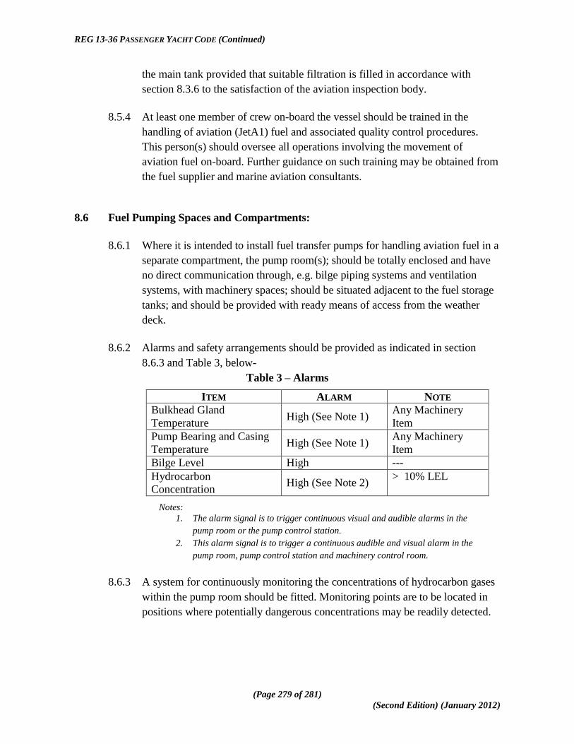
REG 13-36 PASSENGER YACHT CODE (Continued)
(Page 279 of 281)
(Second Edition) (January 2012)
the main tank provided that suitable filtration is filled in accordance with
section 8.3.6 to the satisfaction of the aviation inspection body.
8.5.4 At least one member of crew on-board the vessel should be trained in the
handling of aviation (JetA1) fuel and associated quality control procedures.
This person(s) should oversee all operations involving the movement of
aviation fuel on-board. Further guidance on such training may be obtained from
the fuel supplier and marine aviation consultants.
8.6 Fuel Pumping Spaces and Compartments:
8.6.1 Where it is intended to install fuel transfer pumps for handling aviation fuel in a
separate compartment, the pump room(s); should be totally enclosed and have
no direct communication through, e.g. bilge piping systems and ventilation
systems, with machinery spaces; should be situated adjacent to the fuel storage
tanks; and should be provided with ready means of access from the weather
deck.
8.6.2 Alarms and safety arrangements should be provided as indicated in section
8.6.3 and Table 3, below-
Table 3 – Alarms
ITEM ALARM NOTE
Bulkhead Gland
Temperature High (See Note 1)
Any Machinery
Item
Pump Bearing and Casing
Temperature High (See Note 1)
Any Machinery
Item
Bilge Level High ---
Hydrocarbon
Concentration High (See Note 2)
> 10% LEL
Notes:
1. The alarm signal is to trigger continuous visual and audible alarms in the
pump room or the pump control station.
2. This alarm signal is to trigger a continuous audible and visual alarm in the
pump room, pump control station and machinery control room.
8.6.3 A system for continuously monitoring the concentrations of hydrocarbon gases
within the pump room should be fitted. Monitoring points are to be located in
positions where potentially dangerous concentrations may be readily detected.

REG 13-36 PASSENGER YACHT CODE (Continued)
(Page 280 of 281)
(Second Edition) (January 2012)
8.7 Ventilation:
8.7.1 Fuel pump room(s), fuel storage room(s) and other closed spaces which contain
fuel handling equipment, and to which regular access is required during stores
handling operations, are to be provided with permanent ventilation system(s) of
the mechanical extraction type.
8.7.2 The ventilation system(s) should be capable of being operated from outside the
compartment being ventilated and a notice should be fixed near the entrance
stating that no person is to enter the space until the ventilation system has been
in operation for at least 15 minutes.
8.7.3 The ventilation system(s) should be capable of 20 air changes per hour, based
on the gross volume of the pump room or space.
8.7.4 Protection screens of not more than 13 millimetres square mesh should be fitted
in outside openings of ventilation ducts, and ventilation intakes should be so
arranged as to minimise the possibility of re-cycling hazardous vapours from
any ventilation discharge opening. Vent exits are to be arranged to discharge
upwards.
8.7.5 The ventilation should be interlocked to the lighting system (except emergency
lighting) such that the pump room lighting may only come on when the
ventilation is in operation. Failure of the ventilation system is not to cause the
lighting to go out and failure of the lighting system is not to cause loss of the
ventilation system.
8.8 Non-sparking Fans for Hazardous Areas:
8.8.1 The air gap between impeller and housing of ventilation fans should be not less
than 0.1 of the impeller shaft bearing diameter or 2 millimetres whichever is the
larger, subject also to compliance with section 8.8.2(e) below. Generally,
however, the air gap need be no more than 13 millimetres.
8.8.2 The following combinations of materials are permissible for the impeller and
the housing in way of the impeller-
(a) impellers and/or housings of non-metallic material, due regard being
paid to the elimination of static electricity;
(b) impellers and housings of non-ferrous metals;
(c) impellers and housings of austenitic stainless steel;
REG 13-36 PASSENGER YACHT CODE (Continued)
(Page 281 of 281)
(Second Edition) (January 2012)
(d) impellers of aluminium alloys or magnesium alloys and a ferrous
housing provided that a ring of suitable thickness of non-ferrous
material is fitted in way of the impeller;
(e) any combination of ferrous impellers and housings with not less than
13 millimetre tip clearance; and
(f) any combination of materials for the impeller and housing which are
demonstrated as being spark proof by appropriate rubbing tests.
8.8.3 The following combinations of materials for impellers and housing are not
considered spark proof and should not be permitted-
(a) impellers of an aluminium alloy or magnesium alloy and a ferrous
housing, irrespective of tip clearance;
(b) impellers of a ferrous material and housings made of an aluminium
alloy, irrespective of tip clearance; and
(c) any combination of ferrous impeller and housing with less than 13
millimetres tip clearance, other than permitted by section 8.8.2(b)
above.
8.8.4 Electrostatic charges both in the rotating body and the casing should be
prevented by the use of antistatic materials (i.e. materials having an electrical
resistance between 5 x 10⁴ ohms and 108 ohms), or special means should be
provided to avoid dangerous electrical charges on the surface of the material.
8.8.5 Type approval tests on the complete fan should be carried out to the satisfaction
of the Classification Society.
8.8.6 Protection screens of not more than 13 mm square mesh should be fitted in the
inlet and outlet of ventilation ducts to prevent the entry of objects into the fan
housing.
8.8.7 The installation of the ventilation units on board should be such as to ensure the
safe bonding to the hull of the units themselves.
(wbr maci work Elements etc. z\MACI work main HD group\01-maci work (1)-legislation\1.01 dev of legislation\1.1.3 secondary\indiv regs\passenger yachts\PY Code\batch 8 drafts
of code\py code (2nd Edition)(wbr final)(31 Jan 2012).docx)